1. Introduction
There is always strong interest in new designs of electrical machines due to the desire to increase the power and torque unit indicators. One way in which this goal can be achieved is through the elimination or at least shortening of the winding front connections. These connections do not participate directly in the energy conversion process, but they are necessary for generating a rotating field during the operation of machines based on the use of this field. TFMs, however, use a completely different operating principle, resulting in the complete absence of front connections.
The design of an electrical machine with a transverse flux was patented in 1888 [
1], and almost a hundred years later it was adapted to modern technical capabilities and technologies [
2]. Over the past 30 years, much research work has been devoted to TFMs, e.g., [
3,
4,
5].
Numerous advantages of this construction have been demonstrated, the most important of which is the much greater ratio of mass and volume to power than exists in other machines. Despite this, TFMs are not widely used and produced at present, probably due to several disadvantages in their construction, the most serious of which are:
- -
the complicated design and, as a result, higher production costs and reduced reliability;
- -
the relatively low use of permanent magnet surfaces, which results in large leakage fluxes;
- -
the large cogging torque.
Since the transverse flux machine is an extremely interesting object from the perspective of the theory of electrical machines, it was considered useful to compare some of its properties with the corresponding features of induction machines and Fractional Slot Concentrated Winding—Permanent Magnet Synchronous Machines (FSCW-PMSM), which are in common use. Over the past 20 years, a series of studies have been published describing their features and performance [
6,
7].
Transverse flux machines have a construction containing electromagnetic circuits in which the lines of force mediating the energy conversion remain in a plane perpendicular to the direction of the motion [
2,
8].
Figure 1 schematically shows the construction of the prototype motor in its most basic form, designed in order to conduct laboratory tests [
9].
The movable element is the steel cylinder 1, external to the armature, with permanent magnets 2 placed on its inner surface. The armature consists of a winding ring 4 with cores 3 covering the winding. The poles dimensions in
Figure 1 are:
h—width in the axial direction,
b—thickness in the circumferential direction,
hM—height. The distance of armature elements (inverted U-shaped cores) in the circumferential direction is 2
τp, where
τp—pole pitch in the circumferential direction. The angular span of the armature cores should be equal or slightly smaller than the angular span of the magnets (in the presented structure it is smaller,
b <
τp). The armature winding has the form of a ring wound in a plane perpendicular to the axis of rotation. The air gap
δ allows the winding to move along with the cores relative to the magnets. Armature cores comprise packages of sheets.
The following engine dimensions were adopted for the simulation: the outer diameter of the rotor yoke Dz = 0.152 m; the outer diameter of the cylindrical surface of the armature Dw = 0.133 m; the air gap δ = 8.4 × 10⁻⁴ m; the height of the magnets hM = 0.0038 m; the dimensions of the armature cores: b = 0.008 m; h = 0.0127 m; the core window 0.02 × 0.02 m; the axial dimension of the core lr = 0.0454 m; the permanent magnet used: µpmr = 1.045; HC = 883,310 A/m.
The arrangement of elements and the relationships between individual dimensions were taken from [
9], including the assumption that the dimensions of the system of three single-phase units must not exceed the external dimensions of the winded stator of the 2.2 kW squirrel-cage induction motor, which is treated as comparative. Therefore, the diameter of the outer ring with magnets
Dz = 152 mm was taken as equal to the outer diameter of the 2.2 kW motor stator yoke. However, the axial dimension of U cores with spaces could not be greater than the value of 170 mm, which is close to the axial dimension of the winding of induction motor package of this size.
The value determining the motor’s properties is the linkage flux of the winding ring, which is produced by permanent magnets. The flux is the sum of magnetic field lines running along the axial fragments of individual U cores. The Finite Element Method (FEM) 2D software was used to determine this flux and its changes caused by the rotor movement, wherein treating the magnetic field in TFM as “flat” is only allowed in limited parts of the machine. A fragment of a two-dimensional model of the field excited using permanent magnets is shown in
Figure 2. It consists of a cross-section of cores and magnets (
Figure 1) with the plane perpendicular to the axis of rotation. The cross-sectional plane runs along the radial axis of the U core sections located on one side of the armature winding.
It was assumed that the sought flux value in the axial section of the core is equal to the flux in the radial section of the core, close to the transition to the axial section. In the “flat” field for the radial section, this can be expressed as:
wherein
h—the pole width in the axial direction (
Figure 1),
—the difference of vector potentials at two selected points outside the core poles [Vs/m].
In the case under consideration,
, it may be called the core flux per unit of its axial dimension, or the unit core flux.
Figure 3 shows the course of changes in the unit flux with a solid blue line
in the core as the rotor rotates by two pole graduations. The amplitude of the first harmonic of the waveform
is
, while the amplitude of the third harmonic is 3.7% of the first, and the others are below 1%.
In
Figure 4, the blue line represents the drawn distribution of the radial induction component in the center of the width of the air gap between the magnets and the core pole U, and the average value of this induction. The induction in the core cross-section for which the flux was calculated can be considered a constant. It is 0.42 T; hence it is almost half of the average induction in the air gap (0.78 T). The reason for this difference is the flux leakage, the lines of which close between the exposed surfaces of the magnets and the sides of the radial sections of the U core.
2. Methods to Reduce Leakage Flux
To reduce the leakage flux, the magnets’ free surfaces must be limited. There are numerous proposed methods to achieve this, some of which are presented in
Figure 5. The “oblique” orientation of the cores can be considered the simplest solution, i.e., orienting them in such a way that the ends of each U core are above two successive elements in a single row of magnets, and not one pair of magnets coming from two parallel series as in
Figure 1. This requires a corresponding increase in the axial dimension of the magnet ring. An illustrative version of this solution is shown in
Figure 5a originating from [
10]. The author presents the magnetic flux path in a single-sided transverse flux machine with twisted stator cores and external rotor permanent magnets. A further development of the method was to provide each end of the core with a trapezoidal ending, i.e., a claw—the idea being to focus the maximum amount of force lines coming out of the magnet on the crevice surface of the core. Instead of surface magnets, as in the structure shown in
Figure 5a, the excitation element is a ring composed of permanent magnets and ferromagnetic inserts. These elements of the ring act as a flux concentrator [
1]. The layout is easier to see in
Figure 5b [
11], which also shows another version of the oblique poles according to [
12].
Cores designed for “oblique” as well as “transverse” alignment are situated in the changing magnetic field while the machine is moving and cannot be solid. Due to the difficulty of using magnetic core sheets, they have to be made of metal powders. However, the use of oblique poles does not eliminate the leakage flux, even after using the hub, and only reduces its impact at the expense of the emergence of a significant construction complication. It can also be seen that when the positions of the cores are changed, the structure formally ceases to be a machine with a transverse flux.
3. The Use of a Flat Core
A traditional slotted flat core can be considered a series of oblique U cores rotated 90 degrees from a transverse position, as in
Figure 5a. The winding inserted into such a core can no longer be a flat ring but must consist of fragments in slots and frontal connections. It can also be formed of coils wound around individual teeth, then connected in a series. This solution doubles the flux linkage with the winding.
Replacing the U armature cores with a traditional slotted cylindrical core causes the leakage flux to be radically reduced, but the winding length increases and the cross-section of the winding is limited by the dimensions of the slot. Because flat cores with a number of slots equal to the number of magnet poles are not used due to the large cogging torque, the operation of such a construction was simulated. The principle of generating torque is identical as in the TFM. The cross-section is shown in
Figure 6. In an unchanged outer steel ring, only one row of magnets was left, with their axial dimension increased to the combined dimension of both rows. The length of the slotted core packet was assumed to be equal to the axial dimension of the U cores. The axial dimensions of the magnets and the core were aligned, preserving the radial dimension of the air gap. It was assumed that the field in such a layout can be treated as flat.
Figure 7 shows the shape of the force lines of the field excited by magnets.
The coils cover individual teeth and are connected alternately in a series. In the de-energized state of the coils, each pair of teeth is influenced by the same magnetomotive force (MMF) of magnets as each U core. Assuming no leakage flux and the linearity of the cores, the flux in the teeth should remain at the same level as the flux in the U cores. Under these conditions, in the circuit made of coils, where the total number of turns is the same as in the ring winding in
Figure 1, a similar electromotive force (EMF) value should be induced while the rotor is moving. The leakage flux, however, reduces the flux in the U cores as it moves away from the magnets; thus the EMF in the circuit composed of the coils around the teeth will be higher than in the winding loop of the TFM.
In
Figure 3, the solid red line shows the course of the unit flux of a single yoke tooth when the rotor rotates by two polar pitches. The amplitude of the flux is more than twice as large as in the U core, while the radial component of the induction at half the width of the air gap in both structures is similar—see
Figure 4, red and blue horizontal lines.
4. Estimation of the Torque
The main component of the torque developed in a single-phase electromagnetic system excited by permanent magnets for most structures equals [
13]:
where
—the winding current,
—the winding linkage flux in a currentless state.
Flux
is a periodic function of the angle of the rotor
; if its changes are close to a sine wave, it can be represented by the formula:
wherein the position of the rotor is
. The symbol
pb represents the number of pole pairs of magnets,
—amplitude of the first harmonic of flux changes
.
To obtain a mean value of the torque different from zero, the winding current should be a similar function of time:
To obtain the mean value of the torque, the pulsation of the current
ωo must be related to the instantaneous speed of the machine
ω according to the formula resulting from the relationship:
For the current pulsation
and the compatible EMF, as well as the current phases, the average value of the torque is:
Other torque components, including the cogging torque, have been neglected.
4.1. Single-Phase TFM—Primary Construction
If the winding is concentrated (
Figure 2), the linkage flux of the winding is
where
pb—the number of armature U cores equal to the number of pole pairs of magnets,
—the number of the coil turns,
—the flux in the axial section of the core length h according to (1):
, where
—the difference of vector potentials
ApmA at two selected points outside the poles of the core of the “A” structure. The amplitude of the first harmonic of the flux changes
and the number of the coil turns can be represented by the formula:
The symbol marks the first harmonic of changes in the unit flux of the “A” structure.
The current
ImA (maximum value) can be replaced by the product:
wherein the respective symbols denote:
jA—the current density,
SCuA—the single conductor cross-section,
kwzA—the factor of filling the surface of a single slot
SuA provided for the winding with turns. In the case under consideration,
SuA is the area of the rectangle between the poles of the core (U core window area in
Figure 1).
After substituting (8) and (9) with (7), the expression for the average value of the torque produced by one segment of classic TFM (one phase) is obtained:
4.2. Single-Phase System with Slotted Core and Concentrated Coils—Proposed Structure
If the circuit is formed from identical series of connected coils wound around each tooth of the core (
Figure 6), wherein the number of teeth is equal to the number of poles of the magnets, the linkage flux of the winding in the currentless state with a full symmetry of the circuit is:
, wherein 2
pb—the number of armature coils is equal to the number of poles of the magnets,
—the number of turns of the coil,
—the flux in the axial section of the core according to (1):
. The amplitude of the first harmonic of the flux changes
can be represented by the formula:
The symbol marks the first harmonic of changes in the unit flux in the middle section of the tooth.
The current
ImB (maximum value) can be replaced by the product:
wherein the respective symbols denote:
jB—the current density,
SCuB—the single conductor cross-section,
kwzB—the factor of filling the surface of a single slot
SuB provided for the winding with turns.
After substituting (11) and (12) with (7), the expression for the average value of the torque produced by one segment of the proposed structure (one phase) is obtained:
The relationship between the mean values of torques
TeavA and
TeavB is defined by the quotient:
Assuming the same current density and the same slot filling with copper, we will get:
For the TFM dimensions presented above and the assumed dimensions of the cylindrical core, the slot cross-section is
SuB = 80.5 mm
2 and for the core length
lFe = 40 mm, we get:
The difference between the torques can be reduced by design measures, in particular by reducing the leakage fluxes in the machine with a transverse flux. The difference will also vary for the various TFM variants already proposed. Both presented single-phase constructions can thus be “roughly” regarded as equivalent.
If we assume, as in the case of an induction motor, a power of 2.2 kW, the slot filling factor
kwz = 0.35 and the current density
j = 6.5 A
sk/mm
2, the value of the torque generated by the classic design TFM according to (10) is:
The torque produced in the system with a traditional (slotted) core, according to (13), is:
In
Figure 8, the blue line shows the changes in
TeB torque, produced by one segment of the proposed construction, when rotating the rotor under the conditions of supplying the winding with alternating current, in phase with the EMF. FEM calculations were made using the FEMM 4.2 software. The horizontal blue line shows the average
TeB torque value. It amounts to 16 Nm; hence it is close to
TeavB determined according to (13). Taking into consideration the nonlinearity of the core, the magnetization characteristic reduces the average torque value to 14.5 Nm, i.e., approx. 10%—the horizontal red line in
Figure 9. The same figure also shows the dependence of the torque on the position of the rotor, taking into consideration the saturation of the core—the red curve. Except for the mean value, torque has a large variable component. Theoretically, its amplitude should be equal to the average value; however, the influence of the cogging torque is visible, which causes a periodic change of the sign of the torque.
Figure 9 shows the first harmonics of the EMF induced in the armature winding resulting from the permanent magnets (solid blue line), the linkage flux with the armature winding under load (solid black line) and the armature flux impact (solid red line). The dotted blue curve corresponds to the voltage waveform on the armature resistance, magnified 10 times. For the assumed number of turns in one coil—8—the rated armature current is 11.5 A (root mean square (RMS) value), and the resistance of the entire winding is 0.44 Ω. For a rotational speed of 1500 rpm, the RMS value of EMF induced by the winding flux linkage is 226 V, with the phase angle between this EMF and the current of 10.8 degrees. This corresponds to the produced torque of 16.2 Nm, hence a value very close to the one previously determined (for the linear magnetization characteristic of the cores). The machine is characterized by its very low armature impact and very good power factor.
5. Three-Phase System
A set of three single-phase systems of slotted flat cores placed on a common shaft with magnets shifted circumferentially by the “electric” angle 2π/3, powered by three-phase currents, will increase the mean torque by a factor of three and thereby radically reduce its variable component—see
Figure 10. As it can be seen from the previous calculations, one segment of the set produces an average torque of 14.5 Nm (considering saturation), so a set of 3 segments with a total axial dimension
Lo ≈ 0.17 m, will generate a torque of 3–14.5 Nm = 43.5 Nm. With a pulsation of 3-phase currents
ωo = 1000π s
−1 (500 Hz) it will issue power 1000π s
−1·43.5 Nm/20 ≈ 6.8 kW for 1500 rpm, thus more than 3 times larger than a squirrel-cage induction motor with an electromagnetic circuit of the same dimensions.
The diameter of the outer ring with magnets was assumed for each segment as
Dz = 152 mm, the core pack length of
lFe = 40 mm and the axial dimension of the coils including the front connections as
lc = 40 mm + 2·6 mm = 52 mm. Assuming a spacing of 7 mm between the segments, the axial dimension of the set of 3 single-phase systems will be
Lo = 3·52 mm + 2·7 mm = 170 mm, which is close to the axial dimension of the wound motor package 2.2 kW. A demonstrative drawing of the proposed 3-phase construction is shown in
Figure 11. The disadvantage of the machine will be the high cogging torque, which will cause noticeable speed fluctuations at low rotational speeds and a small moment of inertia of the driven system. The problem of the TFM cogging torque reduction is quite widely described in the literature, e.g., [
14,
15,
16,
17].
The structure presented in
Figure 6 visually resembles the commonly used multipolar synchronous machines with concentrated fractional windings excited by permanent magnets, e.g., [
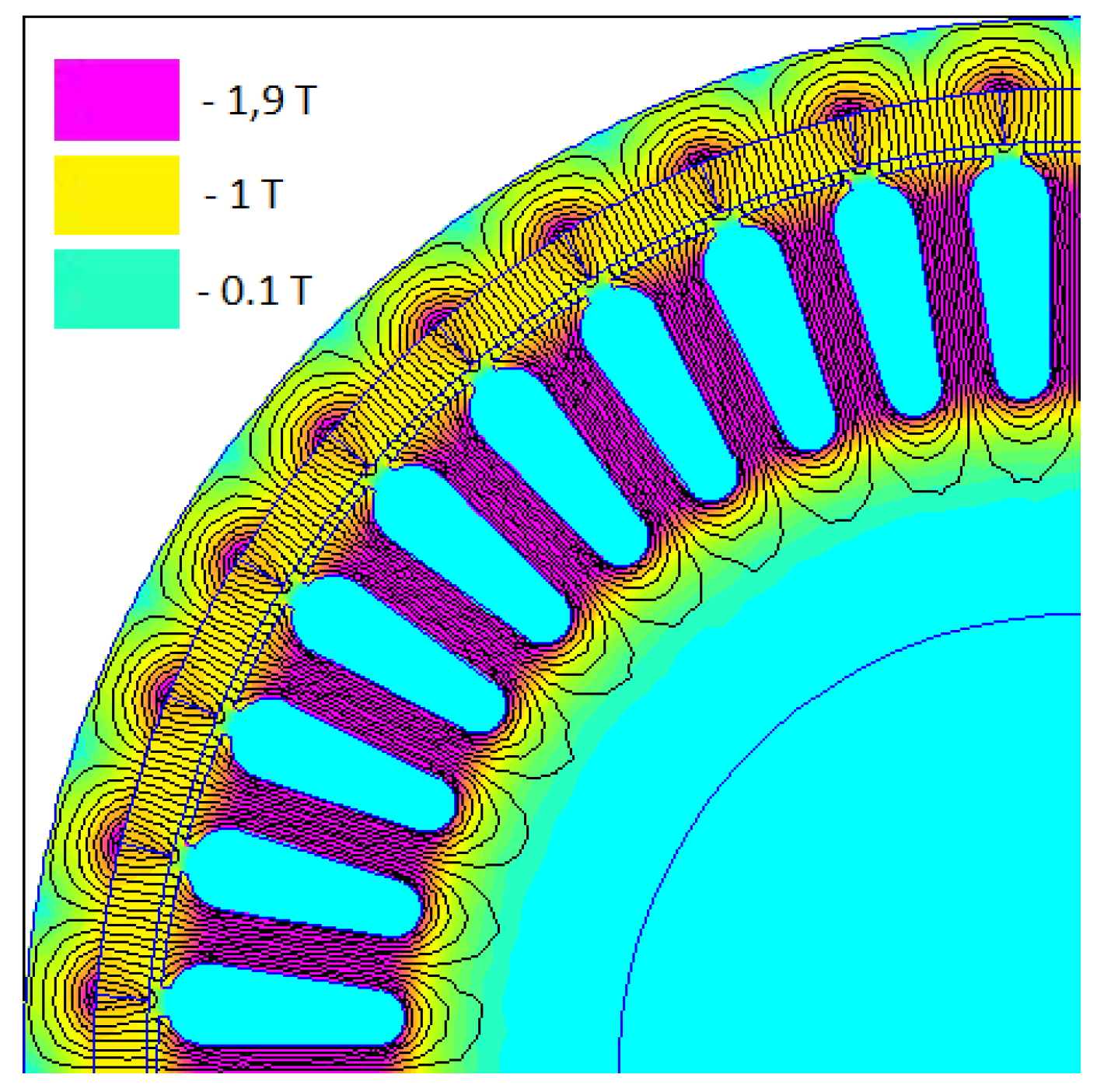
18]. However, they have a multiphase armature and different armature groove pitches and polar excitation. The difference is selected so that in each of the windings made of coils connected in series, EMF are induced, shifted by the angle required for the assumed number of phases. In particular, for example, for the number of poles—40—the closest required number of teeth/ yoke coils would be 36. These designs are widely used and thoroughly tested as Fractional Slot Concentrated Winding—Permanent Magnet Brushless DC (FSCW PMBLDC) and AC motors. A fragment of a cross-section of such a machine is shown in
Figure 12.
Reducing the number of slots enables the slot cross-section to be increased to
Sz = 103 mm
2. For a core package with a length of
lFeg = 0.158 mm, the core dimension together with the short frontal connections around the tooth coils (2 × 6 mm) is close to the total axial dimensions
Lo ≈ 0.17 m of the single-phase core set. The torque generated by such a machine is 23 Nm. Calculations considering saturation, performed in accordance with the FEM method, showed a small variable component, within the range of ±3.3% of the mean value—see
Figure 13.
Thus, in a construction with a three-phase armature, the torque is almost two times lower than that produced by three single-phase systems with slotted flat cores, but the cogging torque is incomparably smaller.


