Article

Recurrence of Sub-Synchronous Oscillation Accident of Hornsea Wind Farm in UK and Its Suppression Strategy

1
Key Laboratory of Distributed Energy Storage and Micro-Grid of Hebei Province, North China Electric Power University, No. 619 Yonghua Road, Baoding 071000, China
2
Research and Development Department, TEMSTEC (Pvt) Ltd., Wah Cantt 47040, Pakistan
*
Authors to whom correspondence should be addressed.
Energies 2021, 14(22), 7685; https://doi.org/10.3390/en14227685
Submission received: 18 August 2021 / Revised: 1 October 2021 / Accepted: 5 October 2021 / Published: 17 November 2021
(This article belongs to the Special Issue Advanced Technologies in Wind Power Generation)

Abstract

:
A large-scale power system breakdown in the United Kingdom caused blackouts in several important cities, losing about 3.2 percent of the load and affecting nearly 1 million power users on 9 August 2019. On the basis of the accident investigation report provided by the UK National Grid, the specific reasons for the sub-synchronous oscillation of Hornsea wind farm were analyzed. The Hornsea wind power system model was established by MATLAB simulation software to reproduce the accident. To solve this problem, based on the positive and negative sequence decomposition, the control strategy of grid-side converter of doubly-fed induction generator is improved to control the positive sequence voltage of the generator terminal, which can quickly recover the voltage by compensating the reactive power at the grid side. Consequently, the influence of the fault is weakened on the Hornsea wind farm system, and the sub-synchronous oscillation of the system is suppressed. The simulation results verify the effectiveness of the proposed control strategy in suppressing the sub-synchronous oscillation of weak AC wind power system after being applied to doubly-fed induction generator, which serves as a reference for studying similar problems of offshore wind power.

1. Introduction

On 9 August 2019, a large-scale blackout occurred in the UK, in which many high-power units were disconnected at the same time. This blackout affected nearly 1 million people. On 6 September 2019, the UK official issued the final investigation reports, sorted out the development process of the accident, analyzed and reflected on the causes of the accident [1,2,3].
Literature [4] proposes to improve the rapidity of load cutting control in view of the independent and concurrent multiple events in the British blackout accident. Literature [5,6,7] points out that a large number of new energy units replace the synchronous machines, which reduces the immunity of the system, worsens the frequency response characteristics of the system, and induces the Hornsea wind farm accident. Sub-synchronous oscillation accident is likely to cause large-scale off-grid of wind turbines and equipment damage, which will have a bad impact on the system stability. Considering that similar lightning strikes frequently occur at the same time of year, and there are many grid-connected points similar to the Hornsea wind farm, therefore, the reasons for the unexpected sub-synchronous oscillation in Hornsea wind farm deserves further study. Literature [8] discusses and considers its oscillation process and analyzes the remaining problems of this oscillation event. However, due to the lack of real-time data, especially the insufficient recordings before and after the oscillation, the subsequent analysis of the oscillation is more difficult. Previous studies on the accident were based on the reports given by the UK National Grid, and did not put forward effective and feasible solutions. Thus, the Hornsea wind power system model simulation is built in MATLAB/Simulink software, reproducing the whole sub-synchronous oscillation accident in this paper. It provides a research basis for improving its control strategy to suppress the sub-synchronous oscillation accident.
At present, the methods to suppress sub-synchronous oscillation of the Hornsea wind power system are mainly divided into three categories: optimizing system parameters, adding sub-synchronous suppression equipment, and installing additional damper controller [9,10,11]. The optimization of system parameters can be realized by changing the system operation state and optimizing the control of the rotor side converter and grid-side converter. In this way, the logic is simple and easy to operate. As the mainstream model in wind farms [12,13], the ability of DFIG to suppress the sub-synchronous oscillation is concerned by many experts and scholars at home and abroad [14,15,16,17,18,19]. In reference [20], the reactive power output capability of the DFIG stator side is deeply excavated and utilized, which improves the flexibility of the reactive power and voltage regulation, but sacrifices its maximum wind energy tracking capability, and reduces the utilization rate of wind energy. Previous studies have shown that the suppression of sub-synchronous oscillation can be achieved by controlling the output of reactive power from the grid-side converter to the power grid, which is easier and more reliable than controlling the motor to output reactive power [21]. Therefore, this paper makes full use of the reactive power adjustment ability of the grid-side converter to quickly recover the grid voltage, weaken the influence of system failure on the Hornsea wind farm, and suppress the sub-synchronous oscillation phenomenon.
Since the sub-synchronous oscillation event of the Hornsea wind farm is caused by the asymmetric drop fault of power grid voltage, there are many asymmetric components and sub-synchronous components in the system. Hence, it reduces the system control accuracy, making it more difficult to suppress the sub-synchronous oscillation and increasing the dynamic coupling between the equipment and the power grid [22,23,24,25,26]. If DFIG control systems do not consider the voltage unbalance, the stator currents can become highly unbalanced even with the small voltage unbalance. The unbalanced currents create unequal heating on the stator windings and oscillations of torque and output power. Control and operation of DFIG systems during network unbalance have been studied in [27,28]. They aim to control the negative sequence current for eliminating the torque and/or power fluctuations; however, contributing to network support is not considered, which is very important [29]. Therefore, it is urgent to explore the voltage compensation capability of the Hornsea wind power system during asymmetric faults to support the recovery of the grid voltage. In reference [30], the current loop control strategy of the doubly-fed induction generator is changed based on positive and negative sequence decomposition to deal with unbalanced network voltage conditions and improve system stability. However, there are problems in the parameter coordination of positive and negative sequence PI regulators in practical application. Literature [31] points out that when asymmetric faults occur, the asymmetric faults can be simplified to symmetric faults by simply compensating the positive sequence voltage to the required reference voltage value, which simplifies the control strategy of the system.
Based on the above analysis, combined with the idea of positive and negative sequence decomposition to solve the sub-synchronous oscillation accident caused by an asymmetric fault in the Hornsea wind farm, the control of the grid-side converter is improved. While maintaining the stability of the DC bus voltage, the control of the positive sequence voltage of the generator terminal is increased, the reactive power on the grid side is compensated to recover the voltage quickly, the influence of the system fault on the Hornsea wind farm is weakened, and the sub-synchronous oscillation of the system is suppressed. The simulation model of the Hornsea wind power system is constructed by using MATLAB software to reproduce the accident and verify the effectiveness of the proposed strategy.

2. Introduction of Hornsea Wind Farm Accident

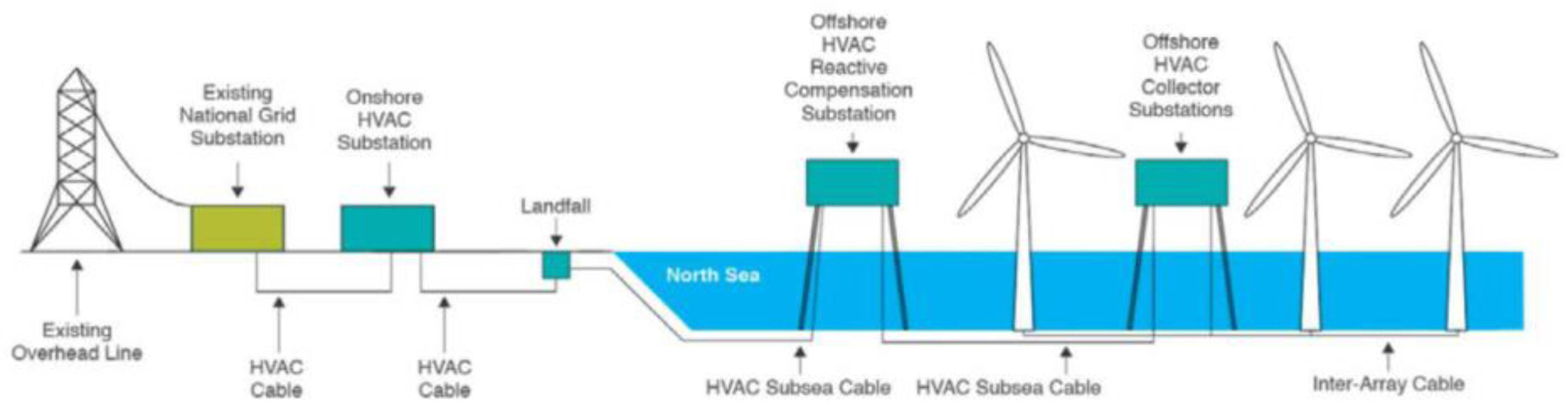
2.1. Hornsea Wind Farm

The geographical location of Hornsea offshore wind farm is shown in Figure 1 [2], which is about 120 km from the Yorkshire coast.
As shown in Figure 2 [2], the wind farm is divided into three parts: Hornsea 1A, Hornsea 1B, and Hornsea 1C. Each section of the wind farm, with a total installed capacity of about 400 MW, is connected to its own HVAC Collector Substation, and then to a HVAC Reactive Compensation Station located offshore before connecting into an Onshore HVAC Substation, and finally to the UK National Grid substation. Before the blackout, the actual output of Hornsea wind farm was 799 MW; Hornsea 1B is operating at 400 MW (maximum capacity for that unit).

2.2. Development of Accidents

According to the UK official reports, this paper combs the development of the large-scale disconnection accident at Hornsea wind farm.
The investigation found that about 10 min before the accident, there had been a similar oscillation phenomenon at the Hornsea wind farm. The voltage of the 400 kV high bus voltage of the wind farm dropped 2%, but it did not cause the disconnection of the wind turbines. Figure 3 shows the response of 400 kV bus voltage and reactive power compensation device at that time [2].
Following the abovementioned, about ten minutes later, lightning caused single-phase grounding fault on the line, and the Hornsea wind farm oscillated again and caused large-scale off-grid of wind turbines. Figure 4 depicts the response of Hornsea wind farm during the accident [2].
On 9 August 2019 at 16:52, an unbalanced voltage dip due to an external event occurred at the interface point where Hornsea wind farm connects to National Grid’s 400 kV transmission system. Initially, the offshore wind farm responded as expected by injecting reactive power into the grid thereby restoring the voltage back to nominal. However, in the following few hundred milliseconds, as the wind farm’s active power reduced to cope with the voltage dip and the reactive power balance in the wind farm changed, the majority of the wind turbines in the wind farm were disconnected by automatic protection systems. The de-load was caused by an unexpected wind farm control system response, due to an insufficiently damped electrical resonance in the sub-synchronous frequency range, which was triggered by the event.
From 16:52:33:490 to 16:52:33:728, the sub-synchronous oscillation of the system lasted about 238 ms and passed through about two cycles. The duration of a single oscillation cycle was about 119 ms and the oscillation frequency was about 8.4 Hz.

2.3. Causes of the Accident

For the sub-synchronous oscillation event caused by lightning strike, Hornsea wind farm operator Orsted pointed out that the reason is insufficient damping in the sub-synchronous oscillation frequency range. After being struck by lightning, the equivalent grid strength at the grid-connected point is weak, which causes the oscillation of the reactive power control system. As a result, the wind power gathering station voltage drops sharply, resulting in all wind turbine generators on Hornsea 1B and Hornsea 1C reducing to 0 MW as a result of overcurrent protection in the generators [2,8].
The accident was fundamentally caused by two reasons. On the one hand, the Hornsea offshore wind farm is connected to the UK main power grid through a long distance submarine cable of 120 km. With the increase of the length of high-voltage AC submarine cable, the equivalent grid strength of the grid-connected point of the offshore wind farm weakens, so the support effect of the AC grid on the voltage at the grid-connected point of the Hornsea wind farm decreases. On the other hand, Hornsea wind farm is a long-distance offshore wind power system. In order to compensate the capacitive current of the cable and limit the power frequency overvoltage, Hornsea wind farm uses reactive compensation devices, such as static var compensator (SVC), to improve the transmission capacity of lines and enhance the transient stability of the system. However, due to its unreasonable control mode, the response of SVC has hysteresis, the peaks and valleys of the reactive power output curve are nearly coincident with the over-surge and drop points of the bus voltage, and the regulation of reactive power is in the same direction as the voltage change. Under the combined action of these two factors, sub-synchronous oscillation occurred in Hornsea wind power system.

3. Solutions

When the Hornsea wind power system suffered from asymmetric faults, which caused sub-synchronous oscillation, there were many asymmetric components and sub-synchronous components in the system. As a result, the control accuracy of the system was reduced, which made the SVC unable to provide accurate voltage compensation to support the rapid recovery of the system to a stable state.
Generally speaking, the control goal of GSC is to maintain the stability of DC bus voltage by controlling the active component of current, and the reactive component of current determines the power factor of GSC. In general, the given value of the reactive power is 0. This paper retains the DC bus voltage control under the traditional control. On this basis, the control of reactive current is improved based on the idea of positive and negative sequence decomposition to compensate the reactive power at the grid side, make the voltage recover quickly, and suppress the sub-synchronous oscillation of the system.
If phase A is the fault phase and its voltage drops to k times of the normal voltage, the three-phase voltage after the fault is shown in Equation (1):
{ u A = 2 k U cos ( ω t ) u B = 2 U cos ( ω t 120 ° ) u C = 2 U cos ( ω t 240 ° )
The positive and negative sequence voltage components are shown in Equation (2):
{ u + = k + 2 3 2 U cos ( ω t ) u = k 1 3 2 U cos ( ω t )
The amplitude of positive sequence voltage u + is (k + 2)/(k − 1) times of negative sequence voltage u - . Considering that k value is generally 0.2–1, the amplitude of u + is generally more than 3 times of u - value.
The compensation degree of positive and negative sequence voltage are defined as:
{ Δ u + = u + u + Δ u = u u
In the formula, u″+ is the compensated positive sequence voltage; u″ is the compensated negative sequence voltage.
From the above analysis, it can be seen that Δu is negligible compared with Δu+, so this paper only considers the compensation of positive sequence voltage.
It is known that the positive sequence component of fault voltage is shown in Equation (4):
{ u + A = k + 2 3 2 U cos ( ω t ) u + B = k + 2 3 2 U cos ( ω t 120 ° ) u + C = k + 2 3 2 U cos ( ω t 240 ° )
The negative sequence component of fault voltage is as follows:
{ u - A = k 1 3 2 U cos ( ω t ) u - B = k 1 3 2 U cos ( ω t + 120 ° ) u - C = k 1 3 2 U cos ( ω t + 240 ° )
If the positive sequence voltage after compensation is as shown in Equation (6):
{ u + A = p u A = p 2 U cos ( ω t ) u + B = p u B = p 2 U cos ( ω t 120 ° ) u + C = p u C = p 2 U cos ( ω t 240 ° )
In the formula, p is the recovery factor of the positive sequence voltage.
Without changing the negative sequence voltage, the compensated voltage is as shown in Equation (7):
{ u A = u + A + u A = ( p + k 1 3 ) u A u B = α 2 u + B + α u B = ( α 2 p + k 1 3 ) u B u C = α u + C + α 2 u C = ( α p + k 1 3 ) u C
In the formula, α is 120° rotation factor.
The magnitude relationship between the compensated voltage and the normal voltage can be obtained as shown in Equation (8):
{ u A = 3 p + k 1 3 u A u B = 27 p 2 + ( 2 k 3 p 2 ) 2 6 u B u C = 27 p 2 + ( 2 k 3 p 2 ) 2 6 u C
To restore the failure phase to its normal value, the following should be made:
3 p + k 1 3 = 1
On this basis, the maximum voltage of the non-fault phase is limited to 120% of the normal value, that is:
27 p 2 + ( 2 k 3 p 2 ) 2 6 = 120 %
p1 and p2 are obtained by substituting k into Equations (9) and (10), respectively. The final value of p is shown in Equation (11):
p=min{ p 1 , p 2 }
The reference value of the positive sequence component of the terminal voltage, puabc*, is derived where uabc* is the rated positive sequence component of the terminal voltage. Subtract the puabc* from the actual positive sequence voltage uabc+ and obtain the reference value of the reactive current of the grid-side converter through the PI regulator.
The improved control strategy of the grid-side converter is shown in Figure 5. The reference value of the reactive current is controlled to dynamically adjust the reactive power output to support the recovery of the grid voltage. The compensation problem in the case of asymmetric fault is simplified as compensation for the positive sequence component of voltage, which reduces the complexity of the system, improves the system stability, and suppresses the sub-synchronous oscillation.

4. Verification Based on Simulation

In the MATLAB/Simulink simulation platform, the Hornsea wind power system model is constructed, and the effectiveness of the proposed strategy is verified.

4.1. Simulation Model

MATLAB/Simulink is widely used in complex simulation and design of control theory and digital signal processing because of its wide adaptability, clear structure and flow, fine simulation, being close to reality, high efficiency, and flexibility. According to the introduction of Hornsea wind farm given in the reports [1,2,3], this paper establishes a 1.2 GW Hornsea wind farm system simulation model on MATLAB/Simulink simulation platform, as shown in Figure 6. The Wind farm is divided into three parts: Hornsea 1A, Hornsea 1B, and Hornsea 1C, each with a capacity of 400 MW. Each unit contains 267 doubly-fed induction generators with a rated voltage of 0.69 kV and rated power of 1.5 MW. The wind farm transmits power to the power grid through 120 km high voltage AC submarine cable, with cable resistance of 0.0205 (Ω/km) and reactance of 0.0798 (Ω/km). In this simulation model, the short circuit ratio of the grid-connected point of the wind farm is about 2.8, which belongs to the weak AC system. The intermediate node of the submarine cable is equipped with TSC-TCR type SVC, which consists of a 327 Mvar thyristor control reactor and three 282 Mvar thyristor switched capacitors. It uses constant voltage control and has a voltage PI controller with kp_svc of 5 and ki_svc of 800.
The main control parameters of the simulation model are shown in Table 1.

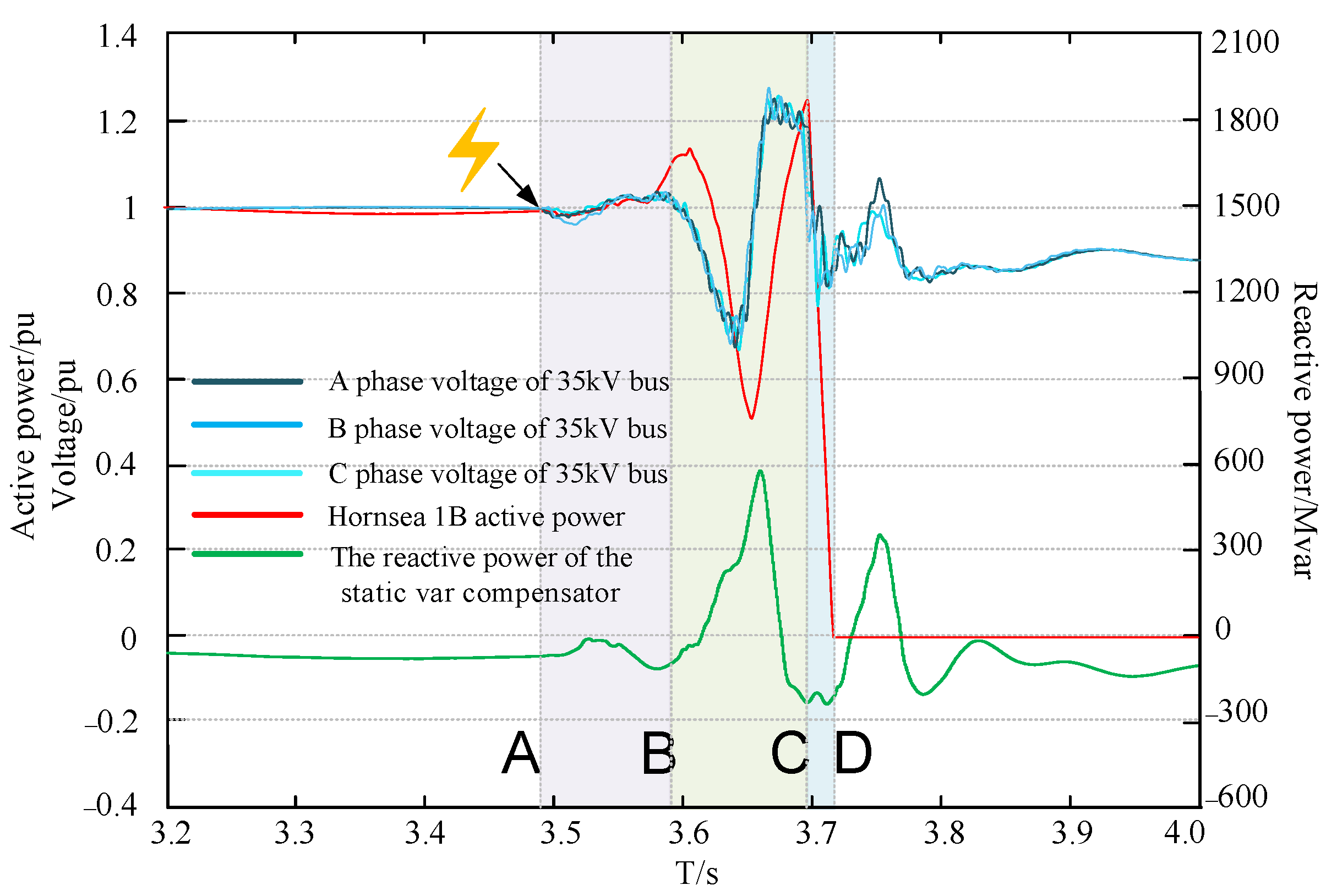
4.2. Recurrence of Accident

Based on the Hornsea wind power system model, the accident processes shown in Figure 3 and Figure 4 are reproduced, and the simulation results are shown in Figure 7 and Figure 8, respectively.
For comparison, considering that the voltage sag of the Hornsea wind farm that caused the blackout accident started at 16:52:33:490, a single-phase voltage sag fault was set at time node A (3.490 s) in the simulation.
It can be found by comparing Figure 4 and Figure 8:
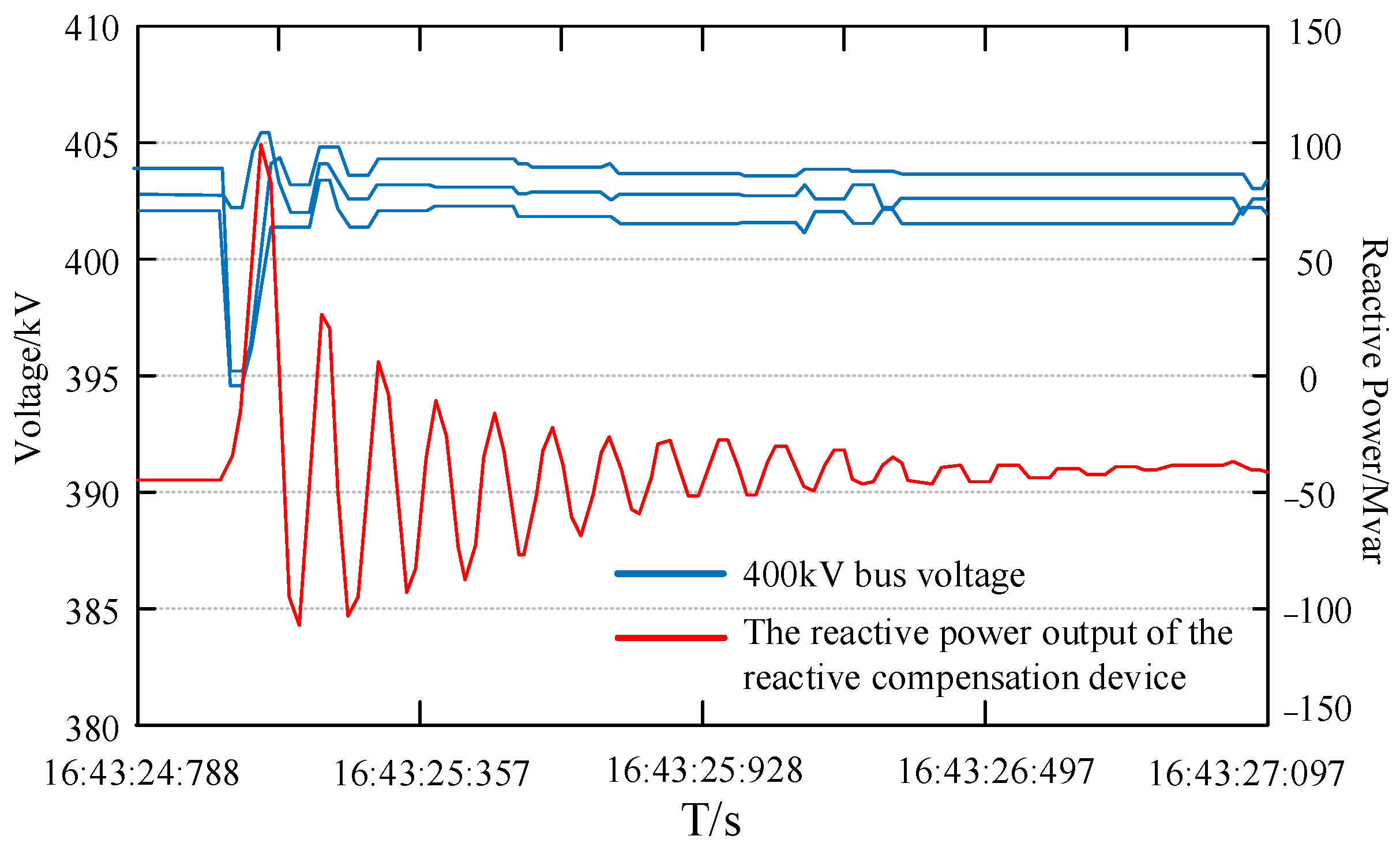
  • During the simulation time of 3.490–3.590 s, within the AB interval, the maximum drop of the 35 kV bus voltage of the Hornsea wind farm is approximately 4%. This corresponds to a 5% drop in the voltage of the 35 kV bus within 16:52:33:490–16:52:33:600.
  • During the simulation time of 3.590–3.695 s, within the BC interval, the voltage of the 35 kV bus of the wind farm drops nearly 35%, and the wind turbine enters the low voltage traversal mode. The active power output of Hornsea 1B drops to about 200 MW and then recovers. It corresponds to that at 16:52:33:600–16:52:33:728, when the active power output of the wind turbine was reduced by about half and then restored.
  • During the simulation time of 3.695–3.715 s, within the CD interval, all wind turbine generators on Hornsea 1B reduce to 0 MW as a result of overcurrent protection in the generators. This corresponds to the disconnection of the wind turbines at 16:52:33:728.
In the simulation, before the wind turbines are disconnected from the grid, the system oscillates roughly for two cycles, the whole duration is about 205 ms, the single oscillation period is about 102.5 ms, and the oscillation frequency is about 9.8 Hz.
The overall reproduction results are basically consistent with the Hornsea wind farm accident phenomenon in the UK. Thus, the accuracy of the wind power system simulation model has been verified.

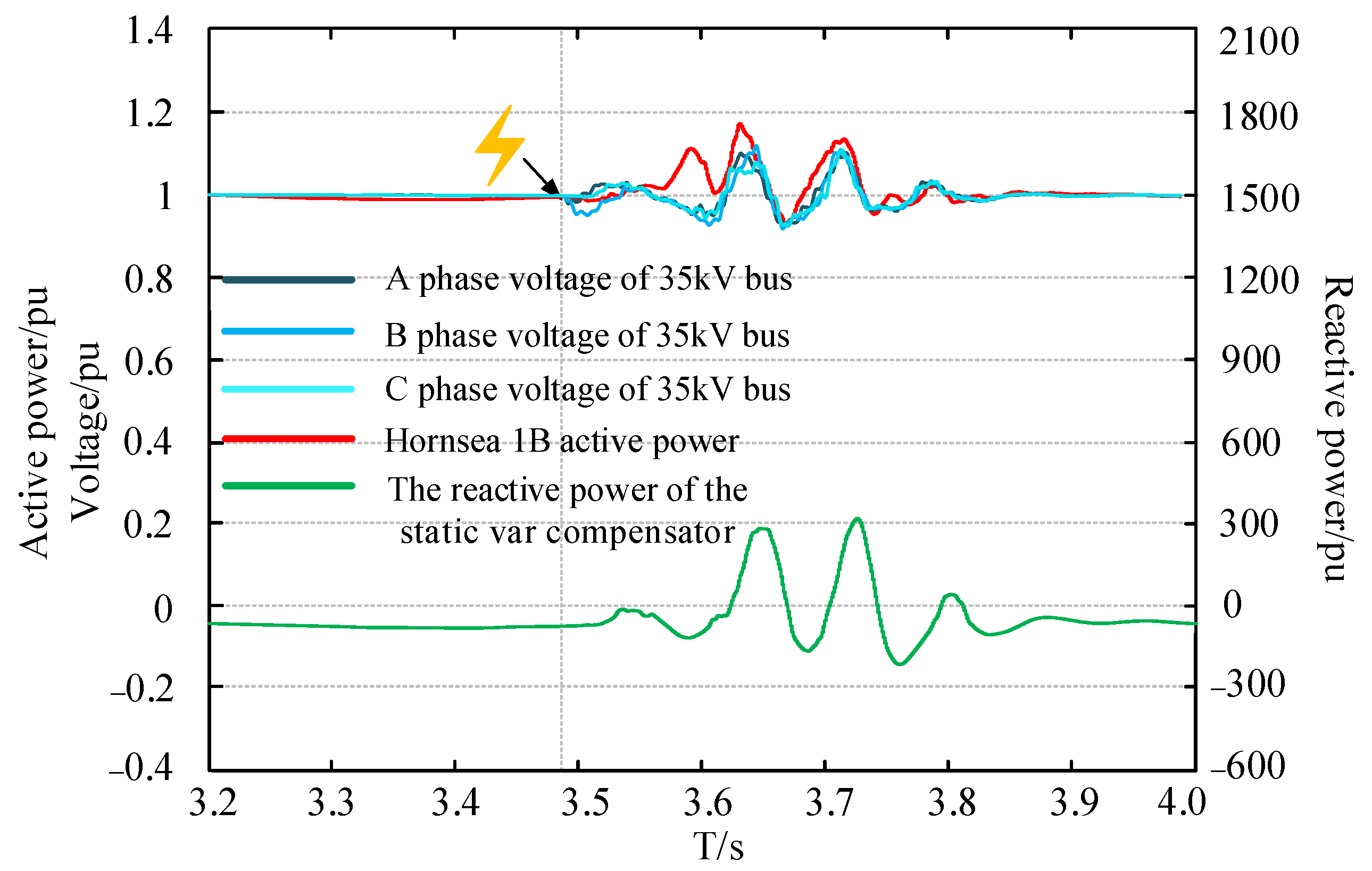
4.3. Verify the Effectiveness of the Proposed Strategy

Based on the accident recurrence model of the Hornsea wind farm, the control strategy proposed in this paper is applied to verify its effectiveness. The simulation results are shown in Figure 9.
It can be seen from Figure 9 that after using the strategy proposed in this paper, the stability of the system is improved and the sub-synchronous oscillation is well suppressed. Compared with the simulation results represented by Figure 8 and Figure 9, the effectiveness of the strategy is further analyzed from the following three aspects.
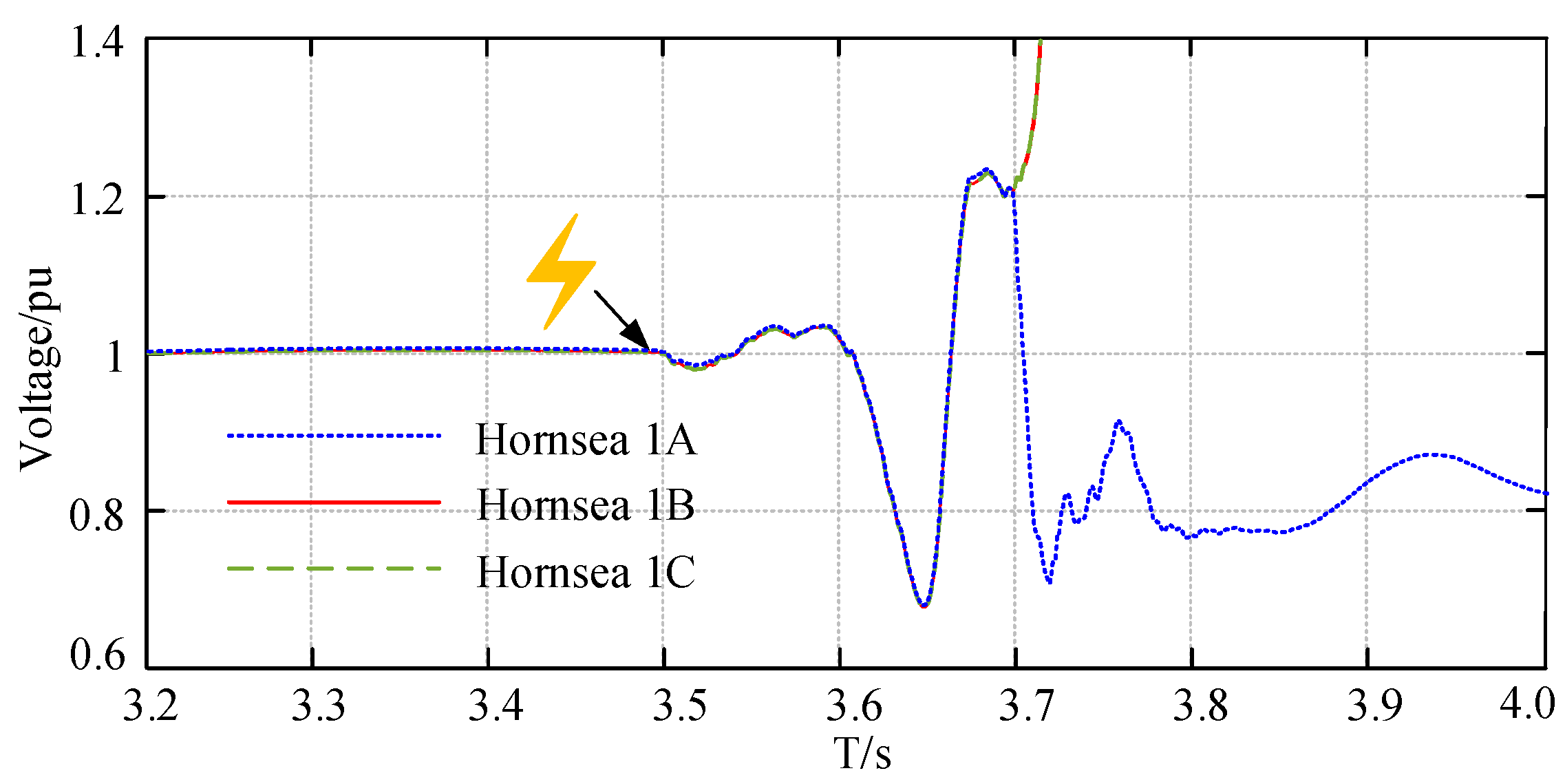
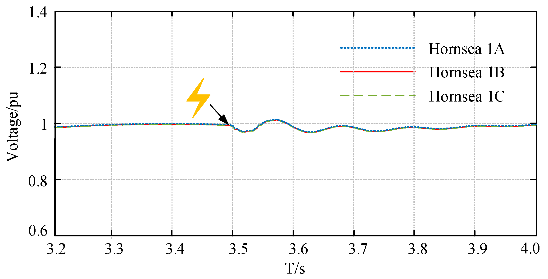
  • Terminal voltage of wind turbines
In the simulation model corresponding to Figure 8, the grid-side converter uses the original control, that is, only maintains the stability of DC bus voltage of the DFIG. The terminal voltage of each wind turbine is shown in Figure 10.
It can be seen that the terminal voltage of Hornsea 1A has not been stabilized in a short time after the Hornsea 1B and 1C are disconnected.
Under the control strategy proposed in this paper, the terminal voltage of each wind turbine is shown in Figure 11.
Combined with Figure 10 and Figure 11, it can be seen that the improved control strategy can effectively promote the stabilization of wind turbine terminal voltage. Under the previous control, the terminal voltage of the wind turbine generator drops to 67.8% of the initial stable value at its lowest point. Under the improved control strategy, the terminal voltage drops to 93.7% at its lowest point. The voltage oscillation amplitude is reduced significantly, which improves the system stability and provides a more stable grid voltage for wind turbines.
2.
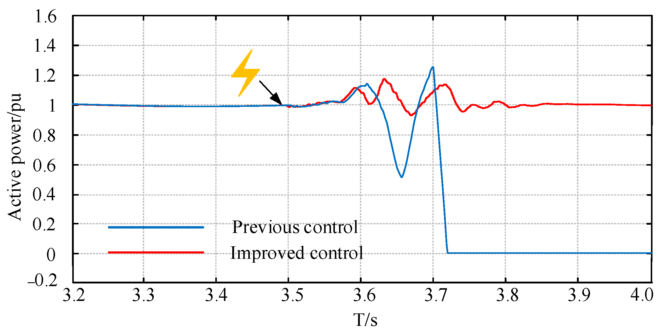
Active power output of Hornsea 1B
The active power output curves of Hornsea 1B are shown in Figure 12. In the off-grid accident of Hornsea wind farm, the active power output of Hornsea 1B dropped from 400 MW (1 pu) to about 200 MW (0.5 pu) and then recovered, but eventually, all wind turbine generators on Hornsea 1B reduced to 0 MW as a result of overcurrent protection in the generators.
After using the strategy proposed in this paper, there is no disconnection of wind turbines, and the output power curve is stable with a small fluctuation range. The active power output of Hornsea 1B only drops to 369.6 MW at the lowest point.
3.
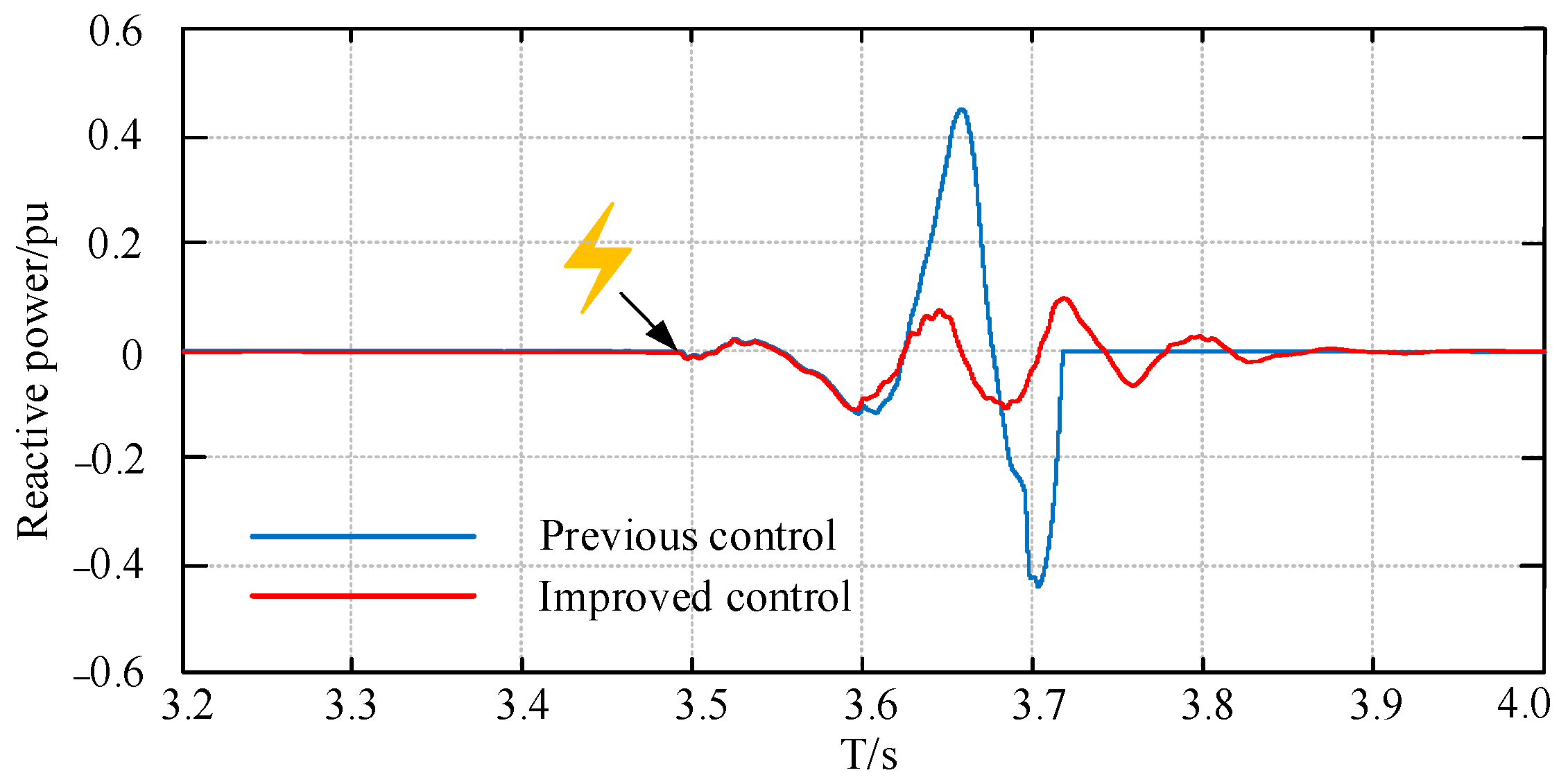
Reactive power output of Hornsea 1B
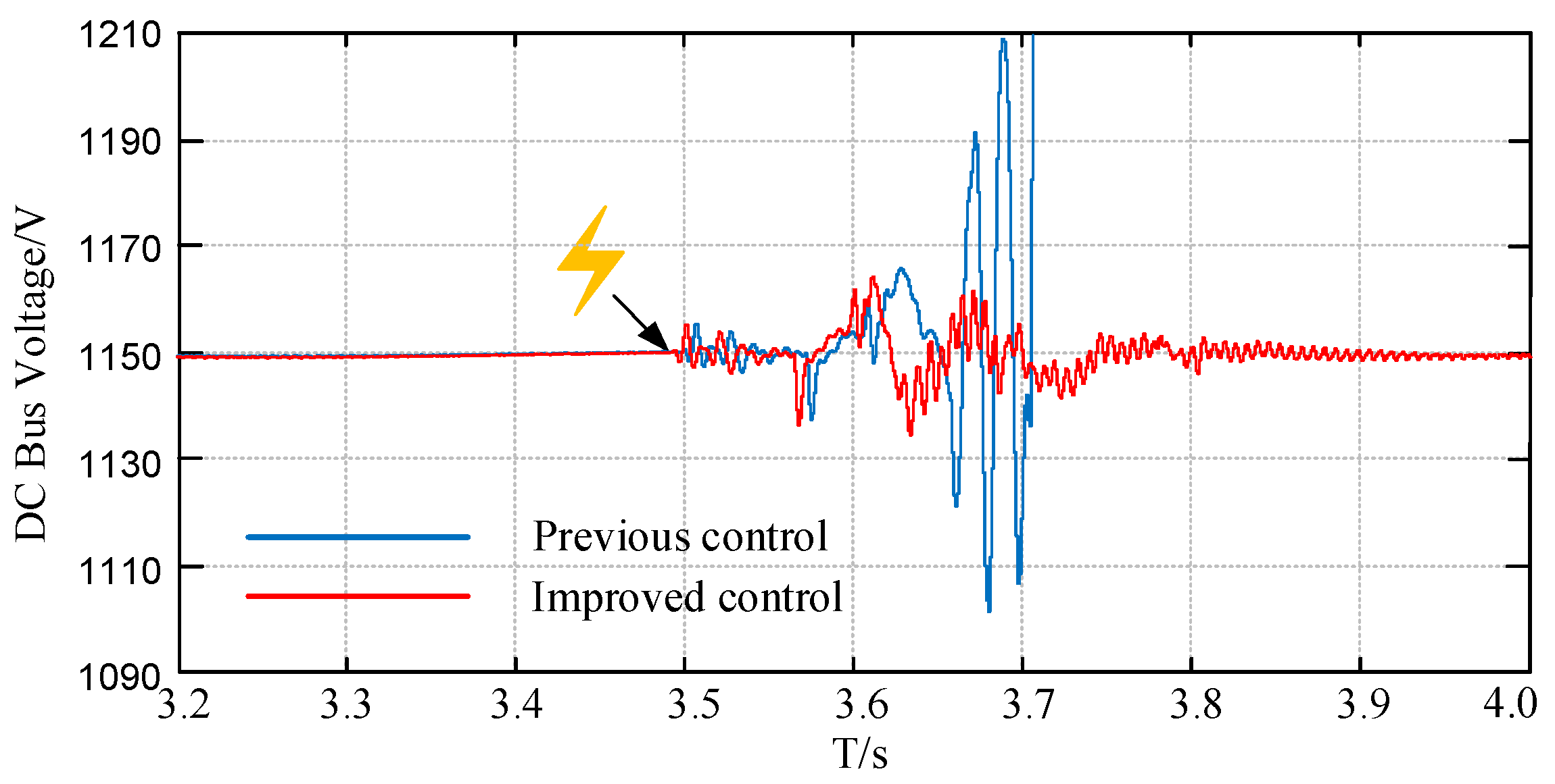
It can be seen from Figure 13 that after the grid failure, the DFIG under the previous control cannot inject suitable reactive power into the grid to stabilize the grid voltage, and its reactive power output oscillates greatly, affecting the recovery of system voltage.
After improving the control strategy of the grid-side converter, it helps to avoid large oscillations of reactive power and restore the voltage to a stable state in a short time.
4.
DC bus voltage
From Figure 14, it can be seen that the DC bus voltage oscillation is obvious before using the strategies mentioned in this paper, and it cannot be stabilized at the rated value after a period of time. After using the strategies mentioned in this paper, the oscillation amplitude of DC bus voltage is significantly reduced, which provides conditions for the normal operation of grid-side converter.

5. Conclusions

This study proposed the control strategy to avoid sub-synchronous oscillation accident by considering a case study of the Hornsea wind power system accidental incident. The paper concluded that:
  • The accident response of a sub-synchronous oscillation event in the Hornsea wind power system is mimicked in MATLAB simulation according to the information provided in British official reports. It is verified that the simulation results are consistent with the actual accident reaction results. It provides a good basis for analyzing the causes of the accident and putting forward specific and feasible solutions.
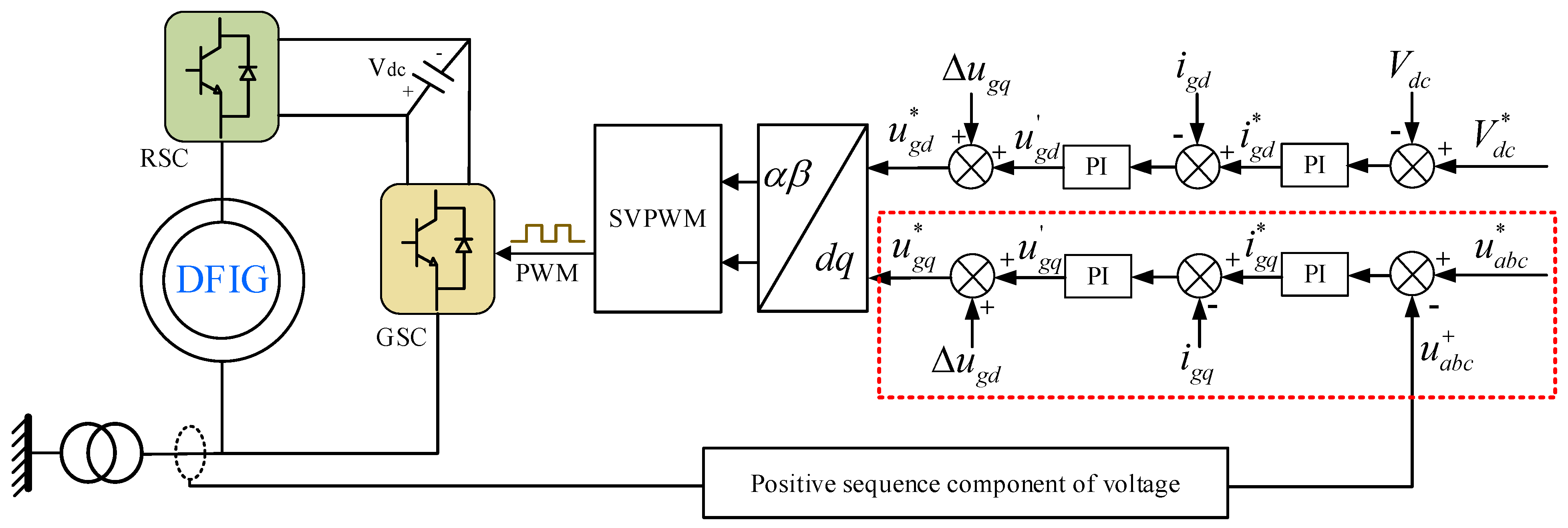
  • The control of the grid-side converter is improved to deal with the sub-synchronous oscillation event caused by asymmetric voltage drop fault in the Hornsea wind power system. It was found that while maintaining the stability of the DC bus voltage, increasing the control of the positive sequence component of terminal voltage and compensating the reactive power will recover the voltage quickly.
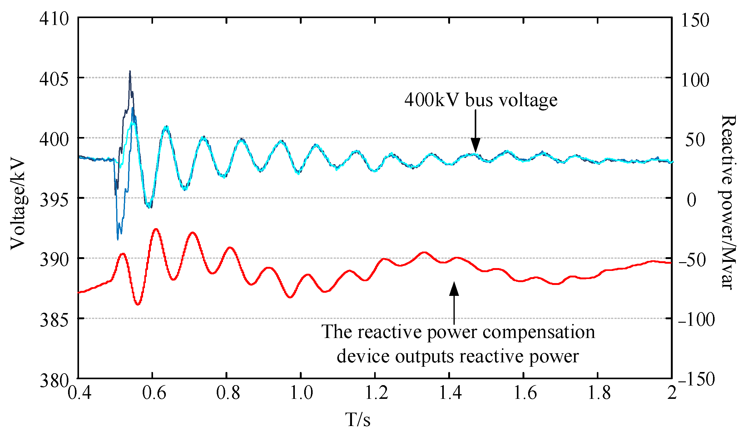
  • The validity of the proposed control strategy to suppress the sub-synchronous oscillation of offshore wind power system is verified by simulation. The simulation results show that the strategy can control the fast and appropriate output of reactive power from the DFIG to the power grid, reduce the voltage oscillation amplitude of the power grid, weaken the influence of system failure on the Hornsea wind farm, smooth the power output of the DFIG, and suppress the sub-synchronous oscillation of the Hornsea wind power system.

Author Contributions

Conceptualization, W.C., X.Y. and S.C.; methodology, W.C., X.Y. and S.C.; software, W.C. and S.C.; validation, W.C.; data curation, W.C.; writing—original draft preparation, W.C.; writing—review and editing, W.C., J.J., A.R., Y.S. and S.C. All authors have read and agreed to the published version of the manuscript.

Funding

This paper was supported by general projects of the Beijing Natural Science Foundation (3212037).

Institutional Review Board Statement

Not applicable.

Informed Consent Statement

Not applicable.

Data Availability Statement

Not applicable.

Acknowledgments

The authors gratefully thank the financial support of the general projects of the Beijing Natural Science Foundation (3212037). The authors of the article appreciate the referees for their valuable suggestions, which contributed to improving the paper.

Conflicts of Interest

The authors declare no conflict of interest.

References

  1. National Grid ESO. Technical Report on the Events of 9 August 2019[EB/OL]. Available online: https://www.nationalgrideso.com/document/152346/download (accessed on 6 September 2019).
  2. National Grid ESO. Appendices to the Technical Report on the Events of 9 August 2019 [EB/OL]. Available online: https://www.ofgem.gov.uk/system/files/docs/2019/09/eso_technical_report_-_appendices_-_final.pdf (accessed on 6 September 2019).
  3. National Grid ESO. Interim Report into the Low Frequency Demand Disconnection (LFDD) following Generator Trips and Frequency Excursion on 9 August 2019[EB/OL]. Available online: https://www.ofgem.gov.uk/system/files/docs/2020/07/national_grid_eso_report_lfdd_9_august_2019.pdf (accessed on 6 September 2019).
  4. Fang, Y. Reflections on Frequency Stability Control Technology Based on the Blackout Event of 9 August 2019 in UK. Autom. Electr. Power Syst. 2019, 43, 1–5. [Google Scholar]
  5. Sun, H.; Xu, T.; Guo, Q.; Li, Y.; Lin, W.; Yi, J.; Li, W. Analysis on blackout in great britain power grid on august 9th,2019 and its enlightenment to power grid in China. Proc. CSEE 2019, 39, 6183–6192. [Google Scholar]
  6. Dian, Y. Analysis of the UK’s blackouts: A large replacement of traditional thermal power by new energy sources will lead to a decline in system inertia levels. Electr. Power Equip. Manag. 2019, 9, 98. [Google Scholar]
  7. Teng, S.; Gong, Y.; Zhang, P.; Li, X. Analysis of great blackout accident in Britain on august 9,2019 and enlightenment to Beijing power network. Electr. Power Surv. Des. 2020, 2, 5–8. [Google Scholar]
  8. Fan, C.; Yao, J.; Zhang, Q.; Xu, C.; Ren, H. Reflection and Analysis for oscillation of the blackout event of 9 august 2019 in UK. Electr. Power Eng. Technol. 2020, 39, 34–41. [Google Scholar]
  9. Ei-Moursi, M.S.; Bak-Jensen, B.; Abdel-Rahman, M.H. Novel STATCOM controller for mitigating SSR and damping power system oscillations in a series compensated wind park. IEEE Trans. Power Electro. 2010, 25, 429–441. [Google Scholar] [CrossRef]
  10. Mohammadpour, H.; Santi, E. SSR damping controller design and optimal placement in rotor-side and grid-side convertors of series compensated DFIG-based wind farm. IEEE Trans. Sustain. Energy 2012, 6, 388–399. [Google Scholar]
  11. Ning, W.; Wu, X.; Guan, Y.; Chen, F. Method to suppress sub-synchronous oscillation of DFIG-based wind farms based on virtual impedance. J. Eng. 2018, 2017, 2173–2177. [Google Scholar] [CrossRef]
  12. Mohamed, M.A.; Diab, A.A.Z.; Rezk, H.; Jin, T. A novel adaptive model predictive controller for load frequency control of power systems integrated with DFIG wind turbines. Neural Comput. Appl. 2019, 32, 7171–7181. [Google Scholar] [CrossRef]
  13. Nian, H.; Xiao, J.; Sciubba, E. Modeling and Analysis of Transient Reactive Power Characteristics of DFIG Considering Crowbar Circuit under Ultra HVDC Commutation Failure. Energies 2021, 14, 2743. [Google Scholar] [CrossRef]
  14. Wu, X.; Guan, Y.; Yang, X.; Ning, W.; Wang, M. Low-cost control strategy based on reactive power regulation of DFIG-based wind farm for SSO suppression. IET Renew. Power Gener. 2019, 13, 33–39. [Google Scholar] [CrossRef]
  15. Wu, X.; Guan, Y.; Ning, W. Reactive power control strategy of DFIG-based wind farm to mitigate SSO. J. Eng. 2017, 2017, 1290–1294. [Google Scholar] [CrossRef]
  16. Wang, Y.; Du, W.; Chen, C.; Zhen, Z.; Wang, H. Investigation on sub-synchronous oscillations in DFIG-based transmission system based on improved complex torque coefficients method. J. Eng. 2019, 2019, 2244–2249. [Google Scholar] [CrossRef]
  17. Jiao, Y.; Li, F.; Dai, H.; Nian, H. Analysis and Mitigation of Sub-Synchronous Resonance for Doubly Fed Induction Generator under VSG Control. Energies 2020, 13, 1582. [Google Scholar] [CrossRef] [Green Version]
  18. Din, Z.; Zhang, J.; Bassi, H.; Rawa, M.; Song, Y. Impact of Phase Locked Loop with Different Types and Control Dynamics on Resonance of DFIG System. Energies 2020, 13, 1039. [Google Scholar] [CrossRef] [Green Version]
  19. Xue, A.; Fu, X.; Wang, Z.; Wang, J. Analysis of Sub-Synchronous Band Oscillation in a DFIG System with Non-Smooth Bifurcation. IEEE Access 2019, 7, 183142–183149. [Google Scholar] [CrossRef]
  20. Gaillard, A.; Poure, P.; Saadate, S. Reactive power compensation and active filtering capability of WECS with DFIG without any over-rating. Wind Energy 2010, 13, 603–614. [Google Scholar] [CrossRef]
  21. Leon, A.E.; Solsona, J.A. Sub-synchronous interaction damping control for DFIG wind turbines. IEEE Trans. Power Syst. 2015, 30, 419–428. [Google Scholar] [CrossRef]
  22. Yan, L.; Yuan, X. Positive and negative sequence control of DFIG based wind turbines and its impact on grid voltage profile concerning converter control capability. J. Eng. 2017, 13, 1584–1589. [Google Scholar] [CrossRef]
  23. Song, F.; Zhu, D.; Tang, K.; Liu, X. Research on the control strategy of dfig grid side converter under unbalanced grid voltage conditions. Appl. Mech. Mater. 2013, 260–261, 454–459. [Google Scholar] [CrossRef]
  24. Zhang, C.; Jiang, D.; Zhang, X.; Liang, Y. Research on an Asymmetric Fault Control Strategy for an AC/AC System Based on a Modular Multilevel Matrix Converter. Energies 2019, 12, 3137. [Google Scholar] [CrossRef] [Green Version]
  25. Son, D.; Kwon, S.; Kim, D.; Song, H.; Lee, G. Control Comparison for the Coordinate Transformation of an Asymmetric Dual Three Phase Synchronous Motor in Healthy and Single-Phase Open Fault States. Energies 2021, 14, 1735. [Google Scholar] [CrossRef]
  26. Benslimane, A.; Bouchnaif, J.; Essoufi, M.; Hajji, B.; Idrissi, L. Comparative study of semiconductor power losses between CSI-based STATCOM and VSI-based STATCOM, both used for unbalance compensation. Prot. Control. Mod. Power Syst. 2020, 5, 56–69. [Google Scholar] [CrossRef]
  27. Brekken, T.; Mohan, N. A Novel Doubly-fed Induction Wind Generator Control Scheme for Reactive Power Control and Torque Pulsation Compensation under Unbalanced grid Voltage Conditions. In Proceedings of the PESC, Acaoulco, Mexico, 15–19 June 2003; Volume 2, pp. 760–764. [Google Scholar]
  28. Wang, Y.; Xu, L. Control of DFIG-based wind generation systems under unbalanced network supply. In Proceedings of the 2007 International Electric Machines & Drives Conference, Antalya, Turkey, 3–5 May 2007; Volume 1, pp. 430–435. [Google Scholar]
  29. Ghennam, T.; Aliouane, K.; Akel, F.; Francois, B.; Berkouk, E.M. Advanced control system of DFIG based wind generators for reactive power production and integration in a wind farm dispatching. Energy Convers. Manag. 2015, 105, 240–250. [Google Scholar] [CrossRef]
  30. Geng, H.; Liu, C.; Yang, G. LVRT capability of DFIG-based WECS under asymmetrical grid fault condition. IEEE Trans. Ind. Electron. 2013, 60, 2495–2509. [Google Scholar] [CrossRef]
  31. Wang, X.; Xian, L.; Bao, G.; Zhang, X.; Ma, C. Compensation method based on positive sequence voltage component under asymmetrical grid fault. Electr. Drive 2015, 45, 63–69. [Google Scholar]
Figure 1. The location of the Hornsea wind farm.
Energies 14 07685 g001
Figure 2. The basic layout description of the Hornsea wind farm.
Energies 14 07685 g002
Figure 3. Response of Hornsea wind farm to voltage drop of 2%.
Energies 14 07685 g003
Figure 4. Development of the accident.
Energies 14 07685 g004
Figure 5. Structure diagram of grid-side converter.
Energies 14 07685 g005
Figure 6. Structure of Hornsea wind farm.
Energies 14 07685 g006
Figure 7. The grid voltage dropped by 2%.
Energies 14 07685 g007
Figure 8. Recurrence of the Hornsea wind farm accident.
Energies 14 07685 g008
Figure 9. Response of Hornsea wind farm under improved control.
Energies 14 07685 g009
Figure 10. The terminal voltage of each wind turbine.
Energies 14 07685 g010
Figure 11. The terminal voltage of each wind turbine under the improved control.
Energies 14 07685 g011
Figure 12. The active power of the Hornsea 1B.
Energies 14 07685 g012
Figure 13. The reactive power of the Hornsea 1B.
Energies 14 07685 g013
Figure 14. The DC bus voltage of the Hornsea 1B.
Energies 14 07685 g014
Table 1. Control parameters of wind power system.
System ComponentsParametersValue
Double-Fed Induction GeneratorRated power Pe/(MW)1.5
Rated voltage Ue/(V)690
Stator resistance Rs/(pu)0.001
Stator leakage inductance L/(pu)0.8
Rotor resistance Rr/(pu)0.01
Rotor leakage inductance L/(pu)0.1
Magnetizing inductance Lm/(pu)2.9
DC bus voltage Vdc/(V)1150
RSCProportional coefficient of current regulator Kp_r0.55
Integration coefficient of current regulator Ki_r8
GSCProportional coefficient of current regulator Kp_g0.9
Integration coefficient of current regulator Ki_g5
Proportional coefficient of DC bus voltage regulator Kp_v5
Integration coefficient of DC bus voltage regulator Ki_v300
TransformerCapacity of main transformer/(MVA)1200
Short circuit impedance of main transformer/(pu)0.068
Capacity of box-type transformer/(MVA)400
Short circuit impedance of box-type transformer/(pu)0.05
Publisher’s Note: MDPI stays neutral with regard to jurisdictional claims in published maps and institutional affiliations.

