
A Review of Extremely Fast Charging Stations for Electric Vehicles


Abstract
:1. Introduction
2. Background Information
3. XFC Charging Station Infrastructure
4. Grid Stability
4.1. Smart Charging
4.2. Vehicle to Grid (V2G)
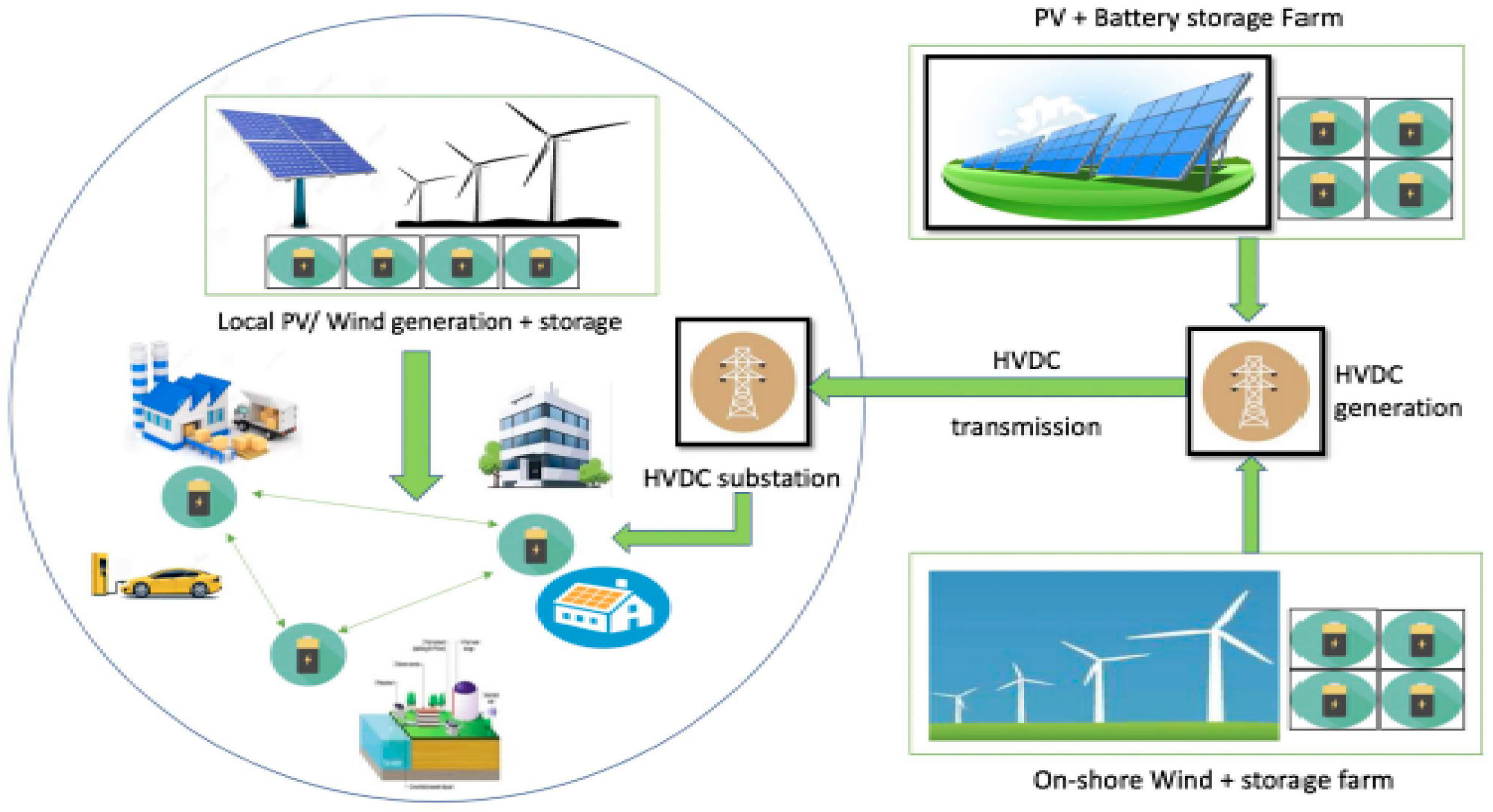
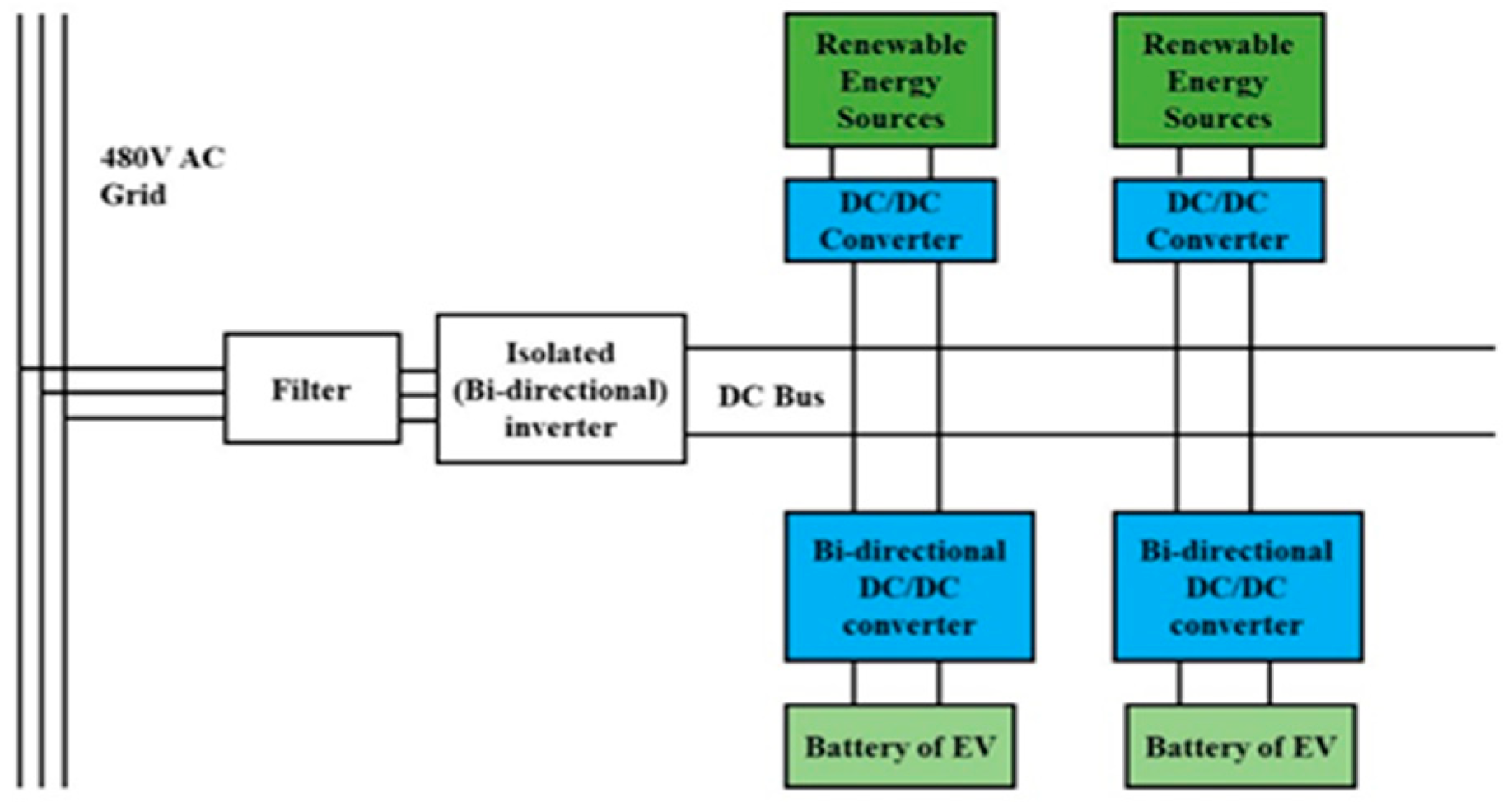
4.3. A Microgrid Ecosystem
- Integrates loads and distributed energy resources, including BESS.
- Compound power generating resources.
- Both grid-connected and be off grid.
- A single unit with its own autonomous control in both approaches.
- Several kilowatts to multiple megawatts with a voltage range up to megavolts can be the power range.
5. Charger Connector Review
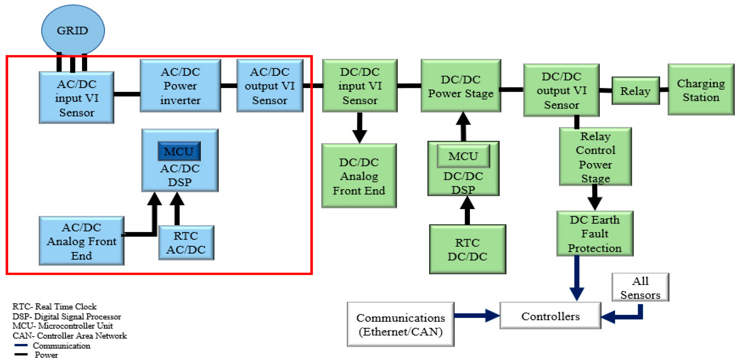
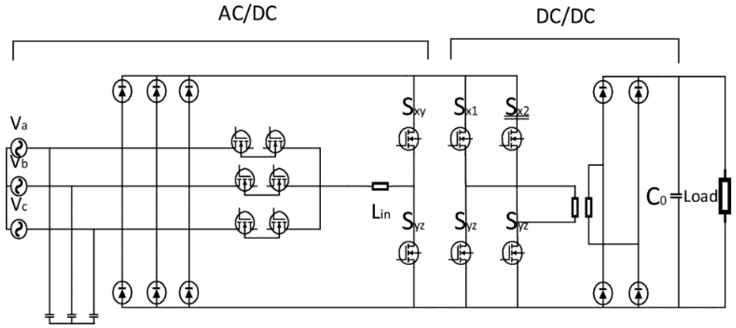
6. Power Electronics
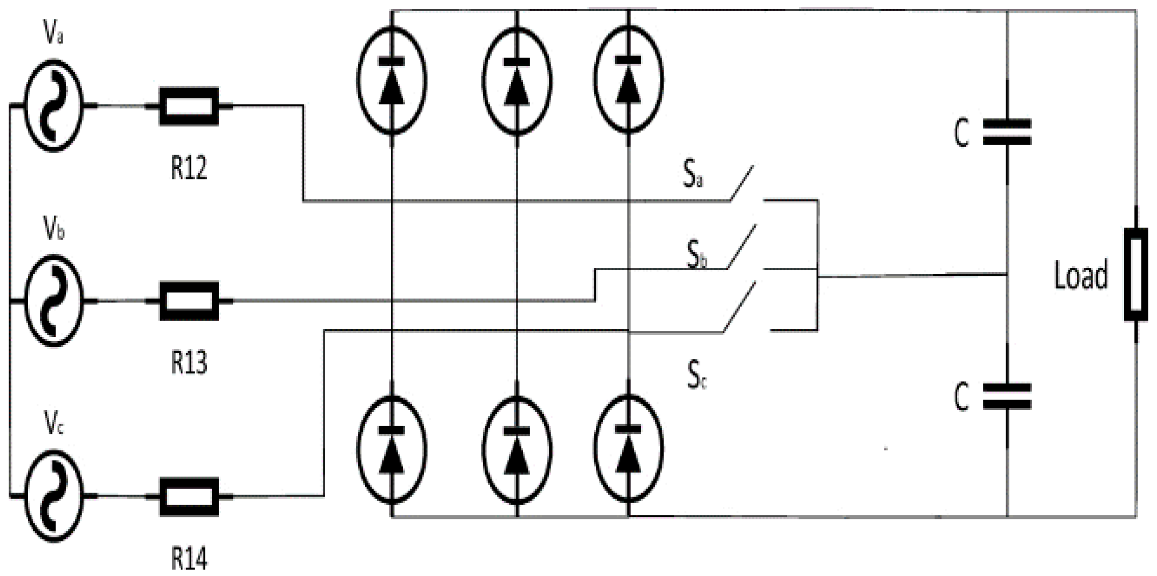
6.1. AC/DC Rectifier Stage
6.1.1. Three Phase PWM Rectifiers
6.1.2. Neutral Point Clamped Converter
6.2. DC/DC Converter Stage
6.2.1. Non-Isolated DC-DC Converter
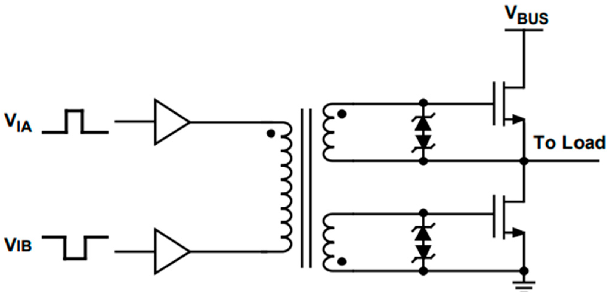
6.2.2. Isolated DC-DC Converter
LLC
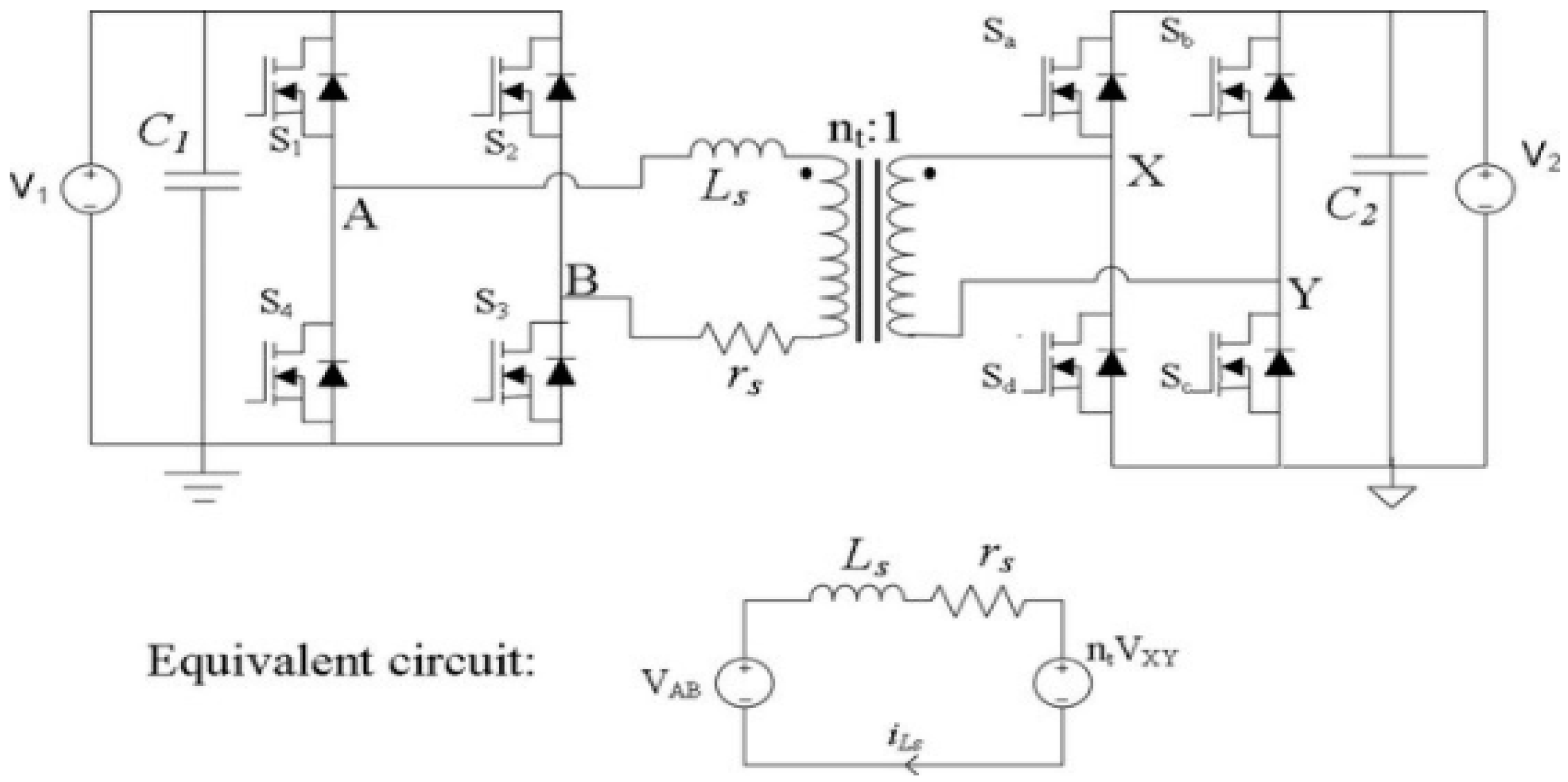
Dual Active Bridge Converter
7. DC Fast Charging (DCFC) Station Cost Analysis
8. Impact on Sustainability
9. The Protection of EVCS
9.1. Line to Ground Fault
9.2. Line to Line Fault
9.3. Overcurrent
9.4. Overvoltage
9.5. AC Circuit Breakers
9.6. DC Protection
10. Reliability
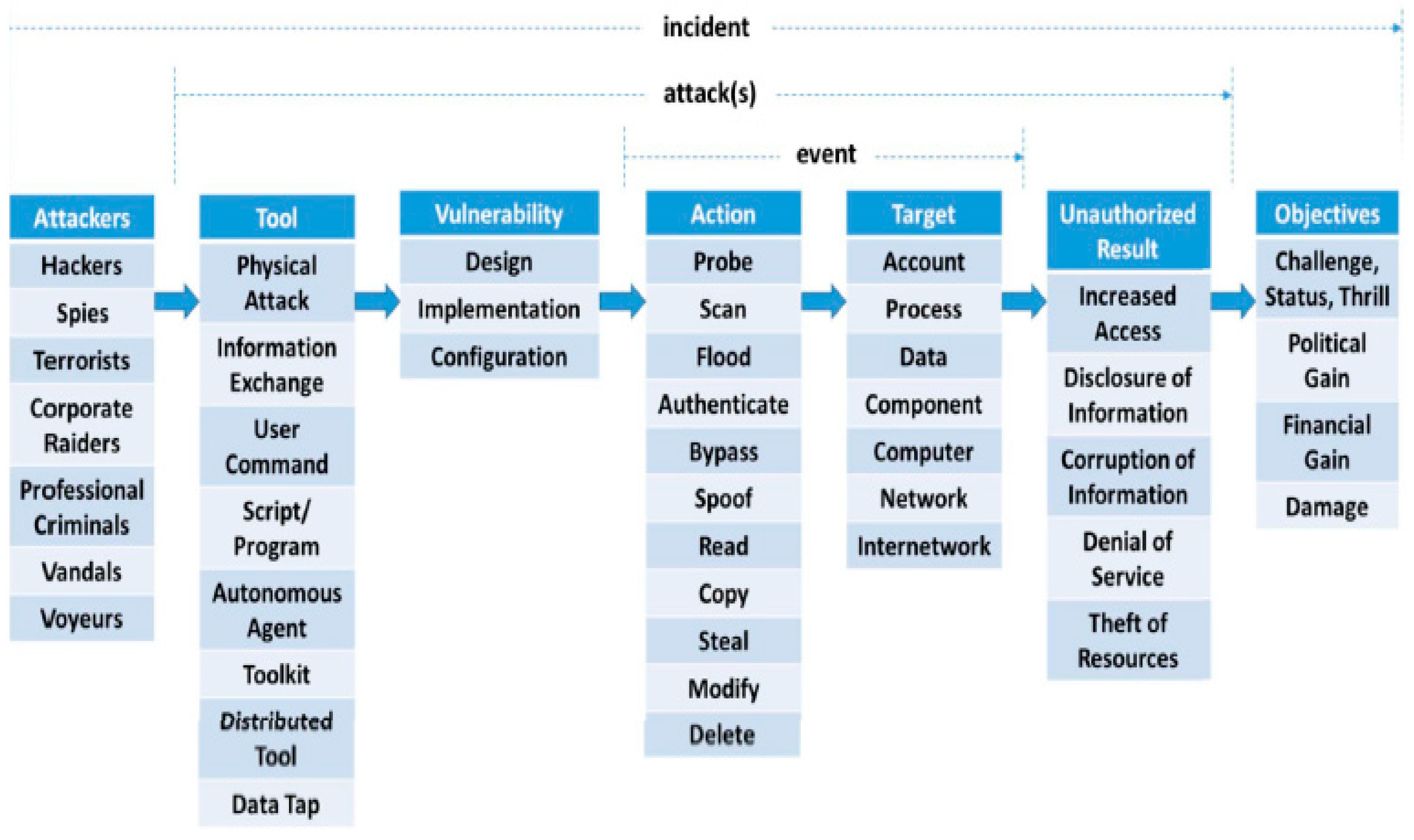
11. Cyber Security for XFC
11.1. Threats in Charging Network during Billing
11.1.1. Man-in-the-Middle-Attack
11.1.2. Other Types of Threats
11.2. Moving Target Based Defense
11.3. Other Mitigation Techniques
12. Transformative Role of Silicon Carbide in DC-Fast Charging
13. Maintenance of XFC
14. Discussion
15. Conclusions
Author Contributions
Funding
Institutional Review Board Statement
Informed Consent Statement
Data Availability Statement
Conflicts of Interest
Nomenclature
| AC | Alternating Current |
| BMS | Battery Management System |
| CPS | Cyber Physical System |
| CHAdeMO | Charge de move |
| CCS | Combined Charging System |
| CAN | Controller Area Network |
| DC | Direct Current |
| DAB | Dual Active Bridge |
| EV | Electric Vehicle |
| ESU | Energy Storage Unit |
| XFC | Extremely fast charging station |
| ICEV | Internal combustion Engine Vehicle |
| ECU | Electronic Control Unit |
| EPA | Environmental Protection Agency |
| EOT | Electrification of Transportation |
| EVCS | Electric Vehicle Charging Station |
| ESR | Electrical Service Requirement |
| IGBT | Insulated Gate Bipolar Transistor |
| kW | Kilowatt |
| HVDC | High Voltage Direct Current |
| MW | Megawatt |
| MVAC | Medium Voltage Alternating current |
| MOSFET | Metal oxide semiconductor field effect transistor |
| PV | Photovoltaic |
| PWM | Pulse Width Modulation |
| RES | Renewable Energy System |
| SoC | state of charge |
| SiC | Silicon Carbide |
| THD | Total harmonic distortion |
| V2G | Vehicle to Grid |
References
- Sources of Greenhouse Gas Emissions. Available online: https://www.epa.gov/ghgemissions/sources-greenhouse-gas-emissions (accessed on 1 November 2021).
- Electric-Vehicle Sales Growth Outpaces Broader Auto Industry. Available online: https://www.wsj.com/articles/electric-vehicle-sales-growth-outpaces-broader-auto-industry-11627032601?mod=hp_lead_pos3&mod=article_inline (accessed on 11 October 2021).
- Electric Airplanes Are Getting Tantalizingly Close to a Commercial Breakthrough. Available online: https://qz.com/1943592/electric-airplanes-are-getting-close-to-a-commercial-breakthrough/ (accessed on 11 October 2021).
- Tesla Working on $25,000 Hatch, Report Says. Available online: https://www.autoweek.com/news/green-cars/a36876395/tesla-working-on-dollar25000-hatch-report-says/ (accessed on 11 October 2021).
- Understanding U.S. and European Standards for Electric-Vehicle Charging. Available online: https://www.electronicdesign.com/power-management/article/21751240/understanding-us-and-european-standards-for-electricvehicle-charging (accessed on 11 October 2021).
- Charging Infrastructure Procurement and Installation. Available online: https://afdc.energy.gov/fuels/electricity_infrastructure_development.html (accessed on 11 October 2021).
- Lessons Learned on Early Electric Vehicle Fast-Charging Deployments. Available online: https://theicct.org/sites/default/files/publications/ZEV_fast_charging_white_paper_final.pdf (accessed on 11 October 2021).
- Tu, H.; Feng, H.; Srdic, S.; Lukic, S. Extreme fast charging of electric vehicles: A technology overview. IEEE Trans. Transp. Electrif. 2019, 5, 861–878. [Google Scholar] [CrossRef]
- Dericioglu, C.; Yirik, E.; Unal, E.; Cuma, M.U.; Onur, B.; Tumay, M. A review of charging technologies for commercial electric vehicles. Int. J. Adv. Automot. Technol. 2018, 2, 61–70. [Google Scholar]
- Shareef, H.; Islam, M.M.; Mohamed, A. A review of the stage-of-the-art charging technologies, placement methodologies, and impacts of electric vehicles. Renew. Sustain. Energy Rev. 2016, 64, 403–420. [Google Scholar] [CrossRef]
- Das, H.S.; Rahman, M.M.; Li, S.; Tan, C.W. Electric vehicles standards, charging infrastructure, and impact on grid integration: A technological review. Renew. Sustain. Energy Rev. 2020, 120, 109618. [Google Scholar] [CrossRef]
- Rafi, M.A.H.; Bauman, J. A Comprehensive Review of DC Fast-Charging Stations with Energy Storage: Architectures, Power Converters, and Analysis. IEEE Trans. Transp. Electrif. 2020, 7, 345–368. [Google Scholar] [CrossRef]
- Tesla Increases Power Capacity of Superchargers in Europe. Available online: https://electrek.co/2019/08/29/tesla-increases-power-superchargers-europe/ (accessed on 11 October 2021).
- Deb, N.; Singh, R.; Bai, H. Transformative Role of Silicon Carbide Power Electronics in Providing Low-cost Extremely Fast Charging of Electric Vehicles. In Proceedings of the 2021 IEEE Fourth International Conference on DC Micro Grids (ICDCM), Arlington, VA, USA, 18–21 July 2021; pp. 1–6. [Google Scholar] [CrossRef]
- Paniyil, P.; Singh, R.; Powar, V.; Deb, N.; Zhang, J.; Bai, K.; Dubey, A. Batteries and Free Fuel based Photovoltaics and Complimentary Wind Energy based DC Power Networks as 100% Source of Electric Power around the Globe. In Proceedings of the 2021 IEEE 48th Photovoltaic Specialists Conference (PVSC), Fort Lauderdale, FL, USA, 20–25 June 2021; pp. 1821–1828. [Google Scholar]
- Yang, S.N.; Cheng, W.S.; Hsu, Y.C.; Gan, C.H.; Lin, Y.B. Charge scheduling of electric vehicles in highways. Math. Comput. Model. 2013, 57, 2873–2882. [Google Scholar] [CrossRef]
- Morrissey, P.; Weldon, P.; O’Mahony, M. Future standard and fast charging infrastructure planning: An analysis of electric vehicle charging behaviour. Energy Policy 2016, 89, 257–270. [Google Scholar] [CrossRef]
- Morrow, K.; Karner, D.; Francfort, J.E. Plug-in Hybrid Electric Vehicle Charging Infrastructure Review; CTCN: Copenhagen, Denmark, 2008. [Google Scholar]
- Hardman, S.; Jenn, A.; Tal, G.; Axsen, J.; Beard, G.; Daina, N.; Figenbaum, E.; Jakobsson, N.; Jochem, P.; Kinnear, N.; et al. A review of consumer preferences of and interactions with electric vehicle charging infrastructure. Transp. Res. Part D Transp. Environ. 2018, 62, 508–523. [Google Scholar] [CrossRef] [Green Version]
- How Will the Grid Adjust to EV Charging? Available online: https://www.tdworld.com/electrification/article/21168252/how-will-the-grid-adjust-to-ev-charging (accessed on 1 November 2021).
- Leite, R.S.; Afonso, J.L.; Monteiro, V. A novel multilevel bidirectional topology for on-board EV battery chargers in smart grids. Energies 2018, 11, 3453. [Google Scholar] [CrossRef] [Green Version]
- Zhang, Z.; Xu, H.; Shi, L.; Li, D.; Han, Y. A unit power factor DC fast charger for electric vehicle charging station. In Proceedings of the 7th International Power Electronics and Motion Control Conference, Harbin, China, 2–5 June 2012; Volume 1, pp. 411–415. [Google Scholar]
- Zhang, Z.; Xu, H.; Shi, L.; Li, D.; Han, Y. Application research of an electric vehicle DC fast charger in smart grids. In Proceedings of the 2012 IEEE 6th International Conference on Information and Automation for Sustainability, Beijing, China, 27–29 September 2012; pp. 258–261. [Google Scholar]
- Du, Y.; Lukic, S.; Jacobson, B.; Huang, A. Review of high power isolated bi-directional DC-DC converters for PHEV/EV DC charging infrastructure. In Proceedings of the 2011 IEEE Energy Conversion Congress and Exposition, Phoenix, AZ, USA, 17–22 September 2011; pp. 553–560. [Google Scholar]
- He, P.; Khaligh, A. Comprehensive analyses and comparison of 1 kW isolated DC–DC converters for bidirectional EV charging systems. IEEE Trans. Transp. Electrif. 2016, 3, 147–156. [Google Scholar] [CrossRef]
- Du, Y.; Zhou, X.; Bai, S.; Lukic, S.; Huang, A. Review of non-isolated bi-directional DC-DC converters for plug-in hybrid electric vehicle charge station application at municipal parking decks. In Proceedings of the 2010 Twenty-Fifth Annual IEEE Applied Power Electronics Conference and Exposition (APEC), Palm Springs, CA, USA, 21–25 February 2010; pp. 1145–1151. [Google Scholar]
- Tank, S.B.; Manavar, K.; Adroja, N. Non-isolated bi-directional DC-DC converters for plug-in hybrid electric vehicle charge station application. In Proceedings of the Emerging Trends in Computer & Electrical Engineering (ETCEE 2015), Rajkot, India, 13–14 March 2015. [Google Scholar]
- Kang, T.; Kim, C.; Suh, Y.; Park, H.; Kang, B.; Kim, D. A design and control of bi-directional non-isolated DC-DC converter for rapid electric vehicle charging system. In Proceedings of the 2012 Twenty-Seventh Annual IEEE Applied Power Electronics Conference and Exposition (APEC), Orlando, FL, USA, 5–9 February 2012; pp. 14–21. [Google Scholar]
- Shi, L.; Xu, H.; Li, D.; Yuan, Z. A novel high power factor PWM rectifier inverter for electric vehicle charging station. In Proceedings of the 2011 International Conference on Electrical Machines and Systems, Beijing, China, 20–23 August 2011; pp. 1–6. [Google Scholar]
- Schupbach, R.M.; Balda, J.C. Comparing DC-DC converters for power management in hybrid electric vehicles. In Proceedings of the IEEE International Electric Machines and Drives Conference, IEMDC’03, Madison, WI, USA, 1–4 June 2003; Volume 3, pp. 1369–1374. [Google Scholar]
- Lee, J.Y.; Jeong, Y.S.; Han, B.M. An isolated dc/dc converter using high-frequency unregulated LLC resonant converter for fuel cell applications. IEEE Trans. Ind. Electron. 2010, 58, 2926–2934. [Google Scholar] [CrossRef]
- Musavi, F.; Craciun, M.; Gautam, D.S.; Eberle, W.; Dunford, W.G. An LLC resonant DC–DC converter for wide output voltage range battery charging applications. IEEE Trans. Power Electron. 2013, 28, 5437–5445. [Google Scholar] [CrossRef]
- Dao, N.D.; Lee, D.C.; Phan, Q.D. High-efficiency SiC-based isolated three-port DC/DC converters for hybrid charging stations. IEEE Trans. Power Electron. 2020, 35, 10455–10465. [Google Scholar] [CrossRef]
- Wang, Y.C.; Wu, Y.C.; Lee, T.L. Design and implementation of a bidirectional isolated dual-active-bridge-based DC/DC converter with dual-phase-shift control for electric vehicle battery. In Proceedings of the 2013 IEEE Energy Conversion Congress and Exposition, Denver, CO, USA, 15–19 September 2013; pp. 5468–5475. [Google Scholar]
- Rivera, S.; Wu, B.; Kouro, S.; Yaramasu, V.; Wang, J. Electric vehicle charging station using a neutral point clamped converter with bipolar DC bus. IEEE Trans. Ind. Electron. 2014, 62, 1999–2009. [Google Scholar] [CrossRef]
- Rajendran, G.; Vaithilingam, C.A.; Naidu, K.; Oruganti, K.S.P. Energy-efficient converters for electric vehicle charging stations. SN Appl. Sci. 2020, 2, 1–15. [Google Scholar] [CrossRef] [Green Version]
- Fathabadi, H. Novel wind powered electric vehicle charging station with vehicle-to-grid (V2G) connection capability. Energy Convers. Manag. 2017, 136, 229–239. [Google Scholar] [CrossRef]
- White, C.D.; Zhang, K.M. Using vehicle-to-grid technology for frequency regulation and peak-load reduction. J. Power Sources 2011, 196, 3972–3980. [Google Scholar] [CrossRef]
- Xu, Z.; Hu, Z.; Song, Y.; Luo, Z.; Zhan, K.; Wu, J. Coordinated charging strategy for PEVs charging stations. In Proceedings of the 2012 IEEE Power and Energy Society General Meeting, San Diego, CA, USA, 22–26 July 2012; pp. 1–8. [Google Scholar]
- Mukherjee, J.C.; Gupta, A. A review of charge scheduling of electric vehicles in smart grid. IEEE Syst. J. 2014, 9, 1541–1553. [Google Scholar] [CrossRef]
- Derakhshandeh, S.Y.; Masoum, A.S.; Deilami, S.; Masoum, M.A.; Golshan, M.H. Coordination of generation scheduling with PEVs charging in industrial microgrids. IEEE Trans. Power Syst. 2013, 28, 3451–3461. [Google Scholar] [CrossRef]
- Koyanagi, F.; Uriu, Y. A strategy of load leveling by charging and discharging time control of electric vehicles. IEEE Trans. Power Syst. 1998, 13, 1179–1184. [Google Scholar] [CrossRef]
- Kesler, M.; Kisacikoglu, M.C.; Tolbert, L.M. Vehicle-to-grid reactive power operation using plug-in electric vehicle bidirectional offboard charger. IEEE Trans. Ind. Electron. 2014, 61, 6778–6784. [Google Scholar] [CrossRef]
- Yong, J.Y.; Ramachandaramurthy, V.K.; Tan, K.M.; Mithulananthan, N. Bi-directional electric vehicle fast charging station with novel reactive power compensation for voltage regulation. Int. J. Electr. Power Energy Syst. 2015, 64, 300–310. [Google Scholar] [CrossRef]
- Andersson, D.; Carlsson, D. Measurement of ABB s Prototype Fast Charging Station for Electric Vehicles. Master’s Thesis, Chalmers University of Technology, Gothenburg, Sweden, 2012. [Google Scholar]
- Camurca, L.; Gao, X.; Costa, L.F.; Liserre, M. Design of a medium voltage dc fast charging station with grid voltage regulation and central modular multilevel converter. In Proceedings of the 2018 IEEE Energy Conversion Congress and Exposition (ECCE), Portland, OR, USA, 23–27 September 2018; pp. 2798–2804. [Google Scholar]
- Wang, W.V.; Thirmawithana, D.J.; Riar, B.; Zane, R. A novel integrated boost modular multilevel converter for high power wireless EV charging. In Proceedings of the 2018 IEEE Energy Conversion Congress and Exposition (ECCE), Portland, OR, USA, 23–27 September 2018; pp. 81–88. [Google Scholar]
- Rubino, L.; Capasso, C.; Veneri, O. Review on plug-in electric vehicle charging architectures integrated with distributed energy sources for sustainable mobility. Appl. Energy 2017, 207, 438–464. [Google Scholar] [CrossRef]
- Nademi, H.; Zadeh, M.; Undeland, T. Interfacing an electric vehicle to the grid with modular conversion unit: A case study of a charging station and its control framework. In Proceedings of the IECON 2018-44th Annual Conference of the IEEE Industrial Electronics Society, Washington, DC, USA, 21–23 October 2018; pp. 5171–5176. [Google Scholar]
- Deb, N.; Singh, R. Cost Efficiency Analysis of a Solar Energy Integrated Fast Charging Station. ENergetics, 15 December 2020. [Google Scholar]
- Nie, Y.M.; Ghamami, M. A corridor-centric approach to planning electric vehicle charging infrastructure. Transp. Res. Part B Methodol. 2013, 57, 172–190. [Google Scholar] [CrossRef]
- Paniyil, P.; Singh, R.; Powar, V.; Venayagamoorthy, G.K. Sustainable Power for Electrification of Transportation. In Proceedings of the 2020 Clemson University Power Systems Conference (PSC), Clemson, SC, USA, 10–13 March 2020; pp. 1–7. [Google Scholar]
- Ashique, R.H.; Salam, Z.; Aziz, M.J.B.A.; Bhatti, A.R. Integrated photovoltaic-grid dc fast charging system for electric vehicle: A review of the architecture and control. Renew. Sustain. Energy Rev. 2017, 69, 1243–1257. [Google Scholar] [CrossRef]
- Preetham, G.; Shireen, W. Photovoltaic charging station for plug-in hybrid electric vehicles in a smart grid environment. In Proceedings of the 2012 IEEE PES Innovative Smart Grid Technologies (ISGT), Washington, DC, USA, 16–20 January 2012; pp. 1–8. [Google Scholar]
- Hu, W.; Su, C.; Chen, Z.; Bak-Jensen, B. Optimal operation of plug-in electric vehicles in power systems with high wind power penetrations. IEEE Trans. Sustain. Energy 2013, 4, 577–585. [Google Scholar]
- McLaren, J.; Miller, J.; O’Shaughnessy, E.; Wood, E.; Shapiro, E. Emissions Associated with Electric Vehicle Charging: Impact of Electricity Generation Mix, Charging Infrastructure Availability, and Vehicle Type (No. NREL/TP-6A20-64852); National Renewable Energy Lab. (NREL): Golden, CO, USA, 2016.
- Dowlatabadi, H.; Krupnick, A.J.; Russell, A. Electric Vehicles and the Environment; U.S. Department of Energy, Office of Scientific and Technical Information: Oak Ridge, TN, USA, 1990.
- Hawkins, T.R.; Gausen, O.M.; Strømman, A.H. Environmental impacts of hybrid and electric vehicles—A review. Int. J. Life Cycle Assess. 2012, 17, 997–1014. [Google Scholar] [CrossRef]
- Paniyil, P.; Powar, V.; Singh, R. Sustainable Intelligent Charging Infrastructure for Electrification of Transportation. Energies 2021, 14, 5258. [Google Scholar] [CrossRef]
- Khaimar, A.K.; Shah, P.J. Study of various types of faults in HVDC transmission system. In Proceedings of the 2016 International Conference on Global Trends in Signal Processing, Information Computing and Communication (ICGTSPICC), Jalgaon, India, 22–24 December 2016; pp. 480–484. [Google Scholar]
- Naveen, G.; Yip, T.H.T.; Xie, Y. Modeling and protection of electric vehicle charging station. In Proceedings of the 2014 6th IEEE Power India International Conference (PIICON), Delhi, India, 5–7 December 2014; pp. 1–6. [Google Scholar]
- Candelaria, J.; Park, J.D. VSC-HVDC system protection: A review of current methods. In Proceedings of the 2011 IEEE/PES Power Systems Conference and Exposition, Phoenix, AZ, USA, 20–23 March 2011; pp. 1–7. [Google Scholar]
- Rodrigues, R.; Du, Y.; Antoniazzi, A.; Cairoli, P. A review of solid-state circuit breakers. IEEE Trans. Power Electron. 2020, 36, 364–377. [Google Scholar] [CrossRef]
- Karunarathna, J.; Madawala, U.; Baguley, C.; Blaabjerg, F.; Sandelic, M. Reliability Analysis of Fast Electric Vehicle Charging Systems. In Proceedings of the 2021 IEEE 12th Energy Conversion Congress & Exposition-Asia (ECCE-Asia), Singapore, 24–27 May 2021; pp. 1607–1612. [Google Scholar]
- Brooks, R.R.; Sander, S.; Deng, J.; Taiber, J. Automobile security concerns. IEEE Veh. Technol. Mag. 2009, 4, 52–64. [Google Scholar] [CrossRef]
- Bedi, G.; Venayagamoorthy, G.K.; Singh, R.; Brooks, R.R.; Wang, K.C. Review of Internet of Things (IoT) in electric power and energy systems. IEEE Internet Things J. 2018, 5, 847–870. [Google Scholar] [CrossRef]
- Compromise of Saudi Aramco and RasGas. Available online: https://www.cfr.org/cyber-operations/compromise-saudi-aramco-and-rasgas (accessed on 1 November 2021).
- Sanger, D.E. The Perfect Weapon: War, Sabotage, and Fear in the Cyber Age; Broadway Books: Portland, OR, USA, 2019. [Google Scholar]
- Russia-Linked Group Hacks 200 Businesses with Ransomware. Available online: https://www.bloomberg.com/news/articles/2021-07-02/russia-linked-group-hacks-about-200-businesses-with-ransomware (accessed on 1 November 2021).
- How China Transformed into a Prime Cyber Threat to the U.S. Available online: https://www.nytimes.com/2021/07/19/technology/china-hacking-us.html (accessed on 1 November 2021).
- Sandworm Team and the Ukrainian Power Authority Attacks. Available online: https://www.fireeye.com/blog/threat-research/2016/01/ukraine-and-sandworm-team.html (accessed on 1 November 2021).
- Falk, R.; Fries, S. Electric vehicle charging infrastructure security considerations and approaches. In Proceedings of the INTERNET 2012: The Fourth International Conference on Evolving Internet, Venice, Italy, 24–29 June 2012; pp. 58–64. [Google Scholar]
- Dierks, T.; Rescorla, E. The Transport Layer Security (TLS) Protocol Version 1.2. [N1]. 2008. Available online: https://ourworldindata.org/ghg-emissions-by-sector (accessed on 1 November 2021).
- Bogosyan, S.; Gokasan, M. Novel Strategies for Security-hardened BMS for Extremely Fast Charging of BEVs. In Proceedings of the 2020 IEEE 23rd International Conference on Intelligent Transportation Systems (ITSC), Rhodes, Greece, 20–23 September 2020; pp. 1–7. [Google Scholar]
- Dospinescu, O.; Perca, M. Technological integration for increasing the contextual level of information. An. Stiintifice Ale Univ. Alexandru Ioan Cuza Din Iasi-Stiinte Econ. 2011, 58, 571–581. [Google Scholar]
- Nabil, M.; Bima, M.; Alsharif, A.; Johnson, W.; Gunukula, S.; Mahmoud, M.; Abdallah, M. Priority-based and privacy-preserving electric vehicle dynamic charging system with divisible e-payment. In Smart Cities Cybersecurity and Privacy; Elsevier: Amsterdam, The Netherlands, 2019; pp. 165–186. [Google Scholar]
- Ito, A.; Ylipää, T.; Gullander, P.; Bokrantz, J.; Centerholt, V.; Skoogh, A. Dealing with resistance to the use of Industry 4.0 technologies in production disturbance management. J. Manuf. Technol. Manag. 2021. [Google Scholar] [CrossRef]
- Bogosyan, S.; Akgul, T.; Gokasan, M. MTD Based Novel Scheme for BMS Security against CAN Bus Attacks during BEV Charging. In Proceedings of the 2020 9th Mediterranean Conference on Embedded Computing (MECO), Budva, Montenegro, 8–11 June 2020; pp. 1–7. [Google Scholar]
- Schneier, B. Click Here to Kill Everybody: Security and Survival in a Hyper-Connected World; WW Norton & Company: New York, NY, USA, 2018. [Google Scholar]
- Anderson, R. Security Engineering: A Guide to Building Dependable Distributed Systems; John Wiley & Sons: Hoboken, NJ, USA, 2020. [Google Scholar]
- Brooks, R.R.; Deng, J. Lies and the lying liars that tell them: A fair and balanced look at TLS. In Proceedings of the Sixth Annual Workshop on Cyber Security and Information Intelligence Research, Oak Ridge, TN, USA, 21–23 April 2010; pp. 1–3. [Google Scholar]
- China Declares All Crypto-Currency Transactions Illegal. Available online: https://www.bbc.com/news/technology-58678907 (accessed on 1 November 2021).
- Miglani, A.; Kumar, N. Deep learning models for traffic flow prediction in autonomous vehicles: A review, solutions, and challenges. Veh. Commun. 2019, 20, 100184. [Google Scholar] [CrossRef]
- Han, O.; Kim, J. Uncertainty analysis on electric power consumption. Comput. Mater. Contin. 2021, 68, 2621–2632. [Google Scholar] [CrossRef]
- Mahmood, N.S.; Ajmi, A.A.; Sarip, S.; Jamaludin, K.R.; Kaidi, H.M.; Talib, H.A. Implications COVID-19 on performance and energy management in the production electricity. Comput. Mater. Contin. 2021, 69, 895–911. [Google Scholar] [CrossRef]
- Frendo, O.; Graf, J.; Gaertner, N.; Stuckenschmidt, H. Data-driven smart charging for heterogeneous electric vehicle fleets. Energy AI 2020, 1, 100007. [Google Scholar] [CrossRef]
- Shahriar, S.; Al-Ali, A.R.; Osman, A.H.; Dhou, S.; Nijim, M. Machine learning approaches for EV charging behavior: A review. IEEE Access 2020, 8, 168980–168993. [Google Scholar] [CrossRef]
- Kharlamova, N.; Hashemi, S.; Træholt, C. The Cyber Security of Battery Energy Storage Systems and Adoption of Data-driven Methods. In Proceedings of the 2020 IEEE Third International Conference on Artificial Intelligence and Knowledge Engineering (AIKE), Laguna Hills, CA, USA, 9–13 December 2020; pp. 188–192. [Google Scholar]
- Charging Infrastructure Operation and Maintenance. Available online: https://afdc.energy.gov/fuels/electricity_infrastructure_maintenance_and_operation.html (accessed on 1 November 2021).
- Why Did Renewables Become So Cheap So Fast? Available online: https://ourworldindata.org/cheap-renewables-growth (accessed on 1 November 2021).
- Saudi Arabia’s Second PV Tender Draws World Record Low Bid of $0.0104/kWh. Available online: https://www.pv-magazine.com/2021/04/08/saudi-arabias-second-pv-tender-draws-world-record-low-bid-of-0104-kwh/ (accessed on 1 November 2021).
- Study Reveals Plunge in Lithium-Ion Battery Costs. Available online: https://news.mit.edu/2021/lithium-ion-battery-costs-0323 (accessed on 1 November 2021).
- This Renewable Energy Juggernaut Wants to Supercharge America’s Battery Storage Capacity. Available online: https://www.fool.com/amp/investing/2020/09/05/this-renewable-energy-juggernaut-wants-to-supercha/ (accessed on 1 November 2021).
- Singh, R.; Shenai, K. DC Microgrids and the Virtues of Local Electricity. IEEE Spectr. 2014, 6. Available online: https://spectrum.ieee.org/dc-microgrids-and-the-virtues-of-local-electricity (accessed on 1 November 2021).
- Singh, R.; Asif, A.A. Ultra large-scale manufacturing challenges of silicon carbide and gallium nitride based power devices and systems. ECS Trans. 2016, 75, 11. [Google Scholar] [CrossRef] [Green Version]


| Type of Fastest Charger Available in Market | Power (kW) | Efficiency | Time to Add 200 Miles |
|---|---|---|---|
| PHIHONG Integrated type | 120 | 93.5% | 30 min |
| Tesla Supercharger | 135 | 91% | 27 min |
| EVTC espresso and charge | 150 | 93% | 24 min |
| ABB terra HP | 350 | 95% | 10 min |
| Shape of Inlet |  |  |  |  |  |
|---|---|---|---|---|---|
| Manufacturer | CCS Combo 1 | CHAdeMO | CCS Combo 2 | GB/T 2D234 DC | Tesla Super Charger |
| Voltage/Power | 600 V/75 kW | 500 V/200 kW | 1000 V/200 kW | 750 V/187.5 kW | 480 V/140 kW |
| 2 Level PWM | 3 Level NPC | |
|---|---|---|
| THD of output current | High | Very low |
| Stress on active and passive devices | High | Low |
| Power Density | Low | High |
| Bidirectional | Yes | Yes |
| Conduction Loss | Low | High |
| Switching Loss | High | Low |
| Efficiency | Low | Very high |
| Cost | Low | High |
| Control | Easy | Mid |
| Input inductor size | Large | Low |
| Thermal management | Easy | Difficult |
| Type | LLC Converter | Dual Active Bridge |
|---|---|---|
| Device stress | Higher | High |
| Transformer Rating | High | Low |
| Input and Output capacitor current | High | Low |
| Operation | Bidirectional | Bidirectional |
| Conduction Losses | High | Lowest |
| Turn ON switching loss | ZVS | ZVS |
| Turn OFF switching loss | Low | High |
| Total losses | Low | Medium |
| Control Complexity | Moderate | Simple to complex |
| Wide battery voltage, fixed bus voltage | No | Yes |
| Paralleling modules | Intensive | Easy |
| Switching frequency | Fixed/high (Si/Sic) | High |
| Attackers | Target | Type of Attack | Result |
|---|---|---|---|
| Spies | Charging Network | Passive | Stolen Financial Information |
| Corporate Hackers | EV | Active | Overcharging the owner |
| Professional Cyber Criminal | Billing info | Passive | Large bill |
Publisher’s Note: MDPI stays neutral with regard to jurisdictional claims in published maps and institutional affiliations. |
© 2021 by the authors. Licensee MDPI, Basel, Switzerland. This article is an open access article distributed under the terms and conditions of the Creative Commons Attribution (CC BY) license (https://creativecommons.org/licenses/by/4.0/).
Share and Cite
Deb, N.; Singh, R.; Brooks, R.R.; Bai, K. A Review of Extremely Fast Charging Stations for Electric Vehicles. Energies 2021, 14, 7566. https://doi.org/10.3390/en14227566
Deb N, Singh R, Brooks RR, Bai K. A Review of Extremely Fast Charging Stations for Electric Vehicles. Energies. 2021; 14(22):7566. https://doi.org/10.3390/en14227566
Chicago/Turabian StyleDeb, Naireeta, Rajendra Singh, Richard R. Brooks, and Kevin Bai. 2021. "A Review of Extremely Fast Charging Stations for Electric Vehicles" Energies 14, no. 22: 7566. https://doi.org/10.3390/en14227566
APA StyleDeb, N., Singh, R., Brooks, R. R., & Bai, K. (2021). A Review of Extremely Fast Charging Stations for Electric Vehicles. Energies, 14(22), 7566. https://doi.org/10.3390/en14227566