1. Introduction
The safety validation in the automotive industry still focuses on the vehicle or system level. Their systems have become increasingly complex so that today’s processes require comprehensive tests to be carried out even at a low hierarchical level, e.g., on component level. This is justified by advances in Software- and Hardware-in-the-Loop testing [
1]. Despite resulting improvements in the reliability of systems, the final safety validation is still only permissible at the system level [
2]. With growing complexity, especially due to the implementation of automated driving functions, it has been shown that field operation tests on system level can no longer be managed economically [
3]. For automated driving functions, scenario-based testing has proved to be a promising approach (see also e.g., [
4,
5]). However, with the validation at the system level, even minor changes and system variations require testing all scenarios again. Furthermore, Amersbach and Winner [
6] point out that a feasible application of scenario-based testing is still challenging due to the required number of scenarios. With the new concept of a modular safety approval, we provide the opportunity to dispense with system tests. The safety approval of modules, as subsystems of the superordinate system “vehicle”, has the advantage that modifications only require repeated approval of the modified modules, not the whole system. In that case, different sets of modules may also be combined to various use cases without the need for a safety approval for every different combination [
7]. To realize such a modular approach, it is crucial to differentiate between the development and testing of systems and of said modules.
Therefore, we analyze the development and testing process in the automotive industry by using a novel developed concept based on well-established risk analysis methods combined with new findings in system theory. Consequently, we indicate possible uncertainties during the development and testing of modules in comparison to the whole system. While the state of the art only tries to reveal errors from the decomposition process in system tests, we present a method that helps to avoid specific errors already during development. Thereby, newly provided awareness of possible uncertainties and rules to avoid them reduces errors in the development process and may also lead to the development of further methods that reduce uncertainty of a modular safety approval. Additionally, the results of this paper can be taken as a starting point to identify more detailed possible errors for a specific development process as well as for a specific system. Further rules can be defined to avoid these errors. Moreover, for some of these errors, module tests can be defined to reveal if they have been put into effect. In summary, the presented approach not only leads, at least, to fewer faults in the integrated system, thus, to fewer revision efforts on system level, but can also guide the way to a modular safety approval.
While various development processes are published in the literature, usually depending on the purpose of the given process, we are going to use the process according to ISO 26262 [
2]. The standard focuses on functional safety which is also a mandatory part of the safety approval for an automated vehicle. The additional publicly available specification SOTIF further considers potential insufficiencies of the intended system functionality but does not include substantial modifications of the process regarding the derivation of subsystems or components [
5]. As ISO 26262 contains a well-established and detailed process description, it is better suited for our following analysis.
The main process in ISO 26262 starts with the definition of the item under consideration. An item is defined as a “system or combination of systems”, while a system is defined as a “set of components or subsystems that relates at least a sensor, a controller and an actuator with one another” [
2]. Similarly, Leveson [
8] (p. 187), as well as Schäuffele et al. [
9] (p. 125), describe three levels of hierarchy: the system, subsystem and component. Both authors point out that systems are always part of a greater system and, thus, subsystem at the same time. Thus, the definition of the hierarchical level depends on the view the hierarchy is used for. On system level, the cumulated functionality that is fulfilled by different subsystems, can be observed in its behavior expressed through its interaction with its operating environment [
10] (p. 6). ISO 26262 uses the vehicle level as the highest considered hierarchical view and the system level as being part of the vehicle. After the analysis of ISO 26262 in this section, we use the term system instead of vehicle, and subsystem (or module) instead of the system to assure the applicability to other domains than the automotive domain.
To understand how the development process of the state of the art lacks in safety validation on lower hierarchical levels, awareness of how these levels are already addressed in the validation is key. ISO 26262 demands the final safety validation to be executed on the vehicle level. Additionally, the standard recommends different test methods linked to particular ASIL (Automotive Safety Integrity Level) classifications on a vehicle, system, and hardware/software level. Hardware/software levels can be components or sets of components being part of the system. With this, potential weaknesses regarding a modular safety approval can be identified. The recommended test methods for the safety validation in ISO 26262 for different hierarchical levels are shown in
Table 1 [
2].
It can be seen that the vehicle level is only missing the back-to-back test. Back-to-back tests are mainly used for the validation of the simulation model. Mostly, a simulation model of the whole vehicle is non-existent or not in the same detail as it is for the investigated system. Thus, the back-to-back test may not be purposeful on the vehicle level. The user test under real-life conditions, missing on hardware/software and system level, can only be performed on the whole vehicle by its definition. However, the real-life conditions and the user can be modeled for simulation, too. With this, at least a user test with uncertainties of validity can be performed on lower levels. The long-term test may conflict with the schedule of the development process, but can also be derived to lower levels with the consideration of uncertainties due to the decomposition.
Two tests that are missing on the hardware/software level in comparison to the system level consider the communication to other hardware/software components. These are only regarded to be possible with finally developed components on system level. Tests from field experience on the hardware/software level are also not recommended by the standard. This may be reasonable because field experiences are only possible in a late stage of the development process. The made experiences can then already be performed on vehicle level. However, breaking down these experiences or derived test cases to lower levels can reduce uncertainty in following development processes.
In conclusion, some test methods may provide the potential to be performed already on the hardware/software level. A deeper analysis of the exact test methods is not the focus of this paper but will be part of our following work. Still, the decomposition of necessary information for tests on lower hierarchical levels is shown to be mandatory to achieve a modular safety approval.
Except for the ISO 26262, the mentioned literature describes subsystems or components as parts of a system, as we will do in the following sections.
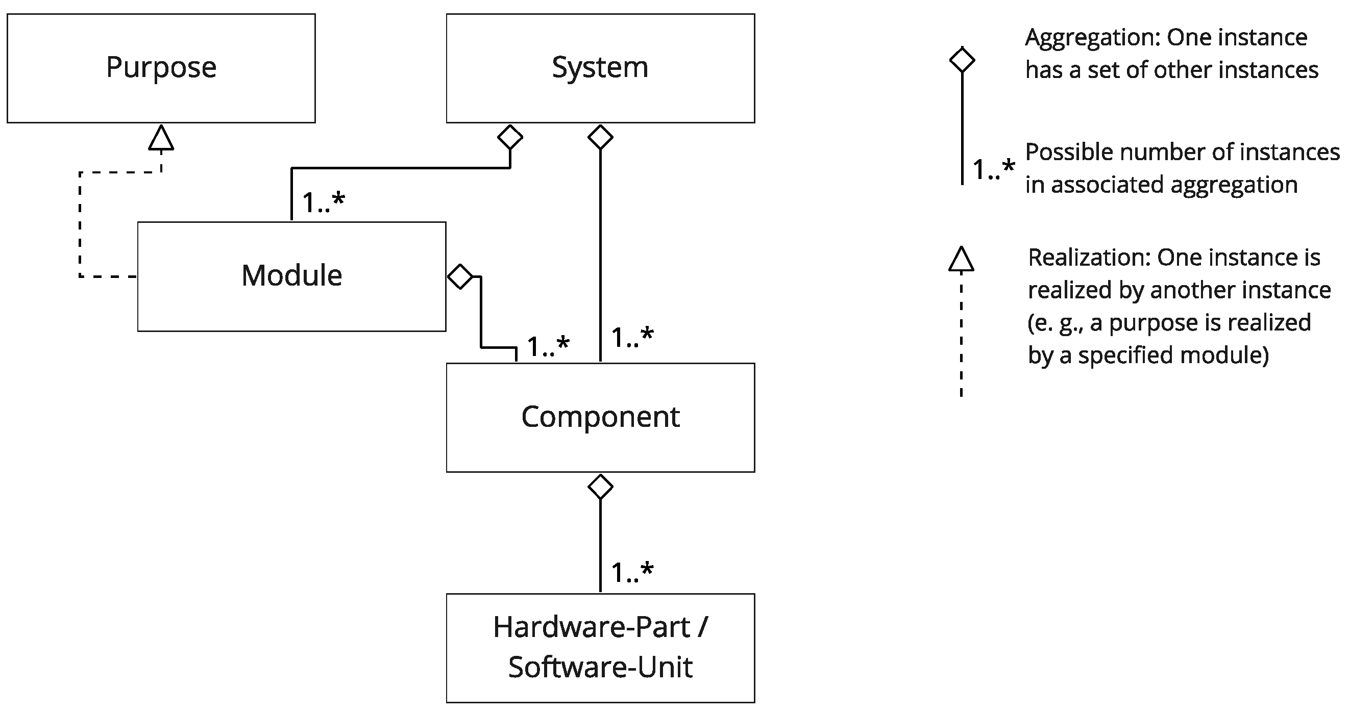
Figure 1 explains the relation between the different hierarchical levels following ISO 26262 [
2] and Steimle et al. [
11] by using the class diagram of the Unified Modeling Language (UML) [
12]. Conforming to Steimle et al., we also include a hierarchy level below with components that are a hardware part and a software unit to show a broader picture of the hierarchies. In this work, we see the vehicle level equivalent to the system level to achieve an approach that can also be applied to other domains. For a subsystem with modular properties, the term module is used. We define a module in the context of this paper as follows:
A module is a set of components building an encapsulated unit with common properties regarding the associated purpose of the modular architecture. With this purpose, a module is relatively independent of other modules but has well-defined interfaces to them.
This definition conforms to Walden et al. [
10] (p. 209) and Göpfert [
13] (p. 27) but adds remarks about the associated purpose. Thereby, it highlights the fact that different modular architectures exist due to different purposes. A system may thus be decomposed into different sets of modules depending on the purpose of the decomposition. In the project UNICAR
agil, a new modular automated vehicle with a service-oriented service architecture is developed, built and safety approved [
7]. The project uses different modular architectures for function, software, hardware and the safety validation. As introduced, the purpose of modularization in this initiative is a modular safety approval. It is remarkable that the consequently developed vehicle system uses different modular architectures with different purposes, which are still interdependent. All architectures are connected to the final implementation of the system and are thus at least connected indirectly. In conclusion, the design of each modular architecture is always a trade-off between the objectives of the different purposes.
2. Materials and Methods
In this chapter, we describe the methods we use to derive rules to avoid errors due to the use of modules, but not the system for the safety validation. For this, revealing possible uncertainty during decomposition processes leading to uncertainty in modular testing is needed. Decomposition is the refinement of a greater entity to smaller entities. In systems engineering, smaller entities are assumed to fulfill the greater entity’s properties [
9] (p. 124). The main view of decomposition lies in the functional decomposition and the decomposition of hardware and software parts. In this work, we also analyze the refinement or decomposition of information, associated with function, hardware and software, such as requirements or parameter spaces [
8] (p. 191). In general, we do not analyze other steps than the ones that derive information from system to module level. Additionally, more than one decomposition step is likely, depending on the level of hierarchy. However, with the assumption that the same methodical steps produce the same categories of uncertainty, we expect only one decomposition step to be sufficient in the analysis.
ISO 26262 is not clear on the point how the overall system or system properties should be decomposed. Although the item definition should be described on vehicle level, the following hazard analysis requires knowledge about the system architecture which can be concluded from the given examples in ISO 26262 [
2] (part 3). Furthermore, it is said that the item definition should contain all already existent ideas of the item and should continuously be refined during development [
2] (part 10). Schäuffele et al. point out that the decomposition process (explicitly referring to hierarchy building and modularization) is often an intuitive process [
9] (p. 126). Thus, when analyzing the way to module development and testing, following the process described in the standard or other literature does not result in a robust structured procedure. Instead, we compare the information mandatory at the system level to the ones derived at the module level. Furthermore, we analyze possible uncertainty in modular testing which may partly be a solution of insufficiencies in the decomposition process.
While the automotive industry focuses on the test procedure for the safety validation [
14] (p. 75), our approach leads to an entire consideration of the development as well as the test procedure. For a modular safety approval, we assume the control of the development process to be mandatory, in particular when it comes to complex functions of an automated vehicle. However, we only consider possible errors in the decomposition process during development until the start of the technical implementation. The specific errors depend on the specific implementation of the development process. These processes vary widely between domains and companies and are analyzed in other publications (cf., e.g., [
15,
16]).
The term error is defined in accordance to Avizienis et al. [
17] as a deviation from a correct state and caused by a fault. A fault as an “abnormal condition that can cause an element or an item to fail” [
18] in decomposition processes can, e.g., be the unawareness of an engineer about possible vehicle states or a misleading used word in the definition of a requirement. An error may lead to a failure, which we define as the termination of an intended behavior in accordance to Stolte et al. [
18], but does not necessarily have to. This is also true for insufficiencies in a decomposition process that may cause a failure but do not necessarily have to. In software engineering, errors are defined as human actions that cause incorrect results [
19]. This definition contradicts the sequence of fault and error of Avizienis [
17] and the ISO 26262 [
2] (part 10). Still, for this work, both definitions of error are convenient. Thus, errors in this work are defined as insufficiencies in decomposition processes (caused by human actions) being deviations from a correct state that may lead to a failure.
The identification of errors is done by using a fault tree analysis starting with an undesired top event, which is then broken down to causes that may lead to it [
20] (IV-1). These causes are seen as another undesired event and broken down into further causes. This is repeated until a general level is reached where the causes can still be applied to arbitrary systems. Causes in a fault tree analysis are faults of the top level event. However, the definition of the terms depends on the perspective taken. With the perspective and scope of this analysis, the identified causes are errors due to the decomposition process or due to the identified differences that appear on module but not on system level. Thus, the findings of this paper are not assumed to be sufficient for a modular safety approval. Further approaches for module and system development as well as testing need to be added. For the supplementation of the fault tree, we are using a similar approach to the System Theory and Process Analysis (STPA) from Leveson et al. [
21] For each of the two identified superordinate errors, a simplified control structure is modeled. The errors identified by the fault tree analysis are assigned to the modeled entities or connections. Entities or connections without assigned errors are analyzed in more detail for possible errors due to the decomposition processes. Newly revealed errors are then added to the fault tree to increase its completeness.
3. Results
On system level according to the item definition in ISO 26262, a functional description, e.g., based on possible use cases of the system, is given [
2] (part 3). This functional description can already be decomposed into a set of functions, building the functional architecture. On the other side, requirements can be derived from the functional description. In ISO 26262, these requirements on vehicle level are called safety goals. The third important information category is hazards, usually described by scenarios that may lead to these hazards. In the domain of automated vehicles, they are called critical scenarios as described by Junietz [
22]. In a previous publication [
23], we already showed how hazards, that may i.a. be derived by the consideration of violated safety goals, can be broken down to the module level. Still, this process can be as erroneous as any other decomposition process that needs to be considered in the safety validation.
On module level, the functional description is derived directly from the functional description of the system or from the requirements on module level that are derived from requirements on system level.
For a modular safety approval, we identified two main requirements that need to be fulfilled. The first requirement is that the module’s function together with the functions of other modules fulfills the requirements on system level. Additionally, the specified requirements of the module need to be fulfilled by the implementation of the module and is defined as the second requirement.
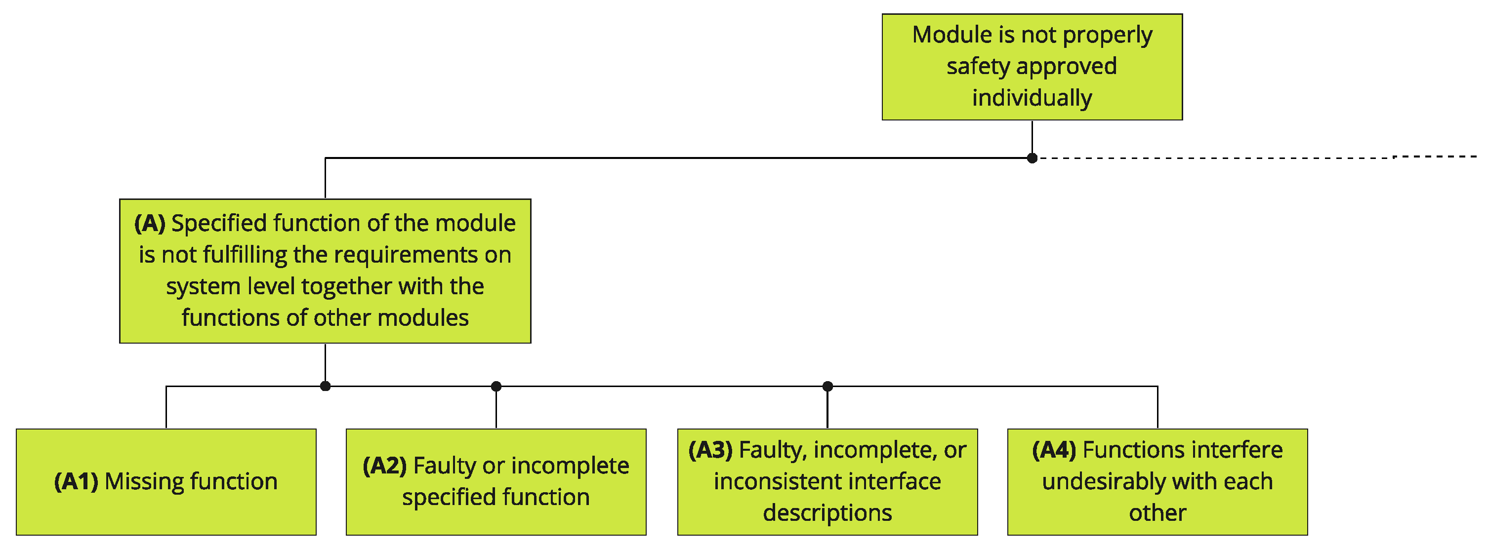
Taking the abovementioned in mind, we use the described fault tree analysis approach with the top event that a
module is not properly safety approved individually, in order to derive possible hazards. On the second level, we assume that at least one of the two main requirements is not fulfilled. For the first error A, it is assumed that
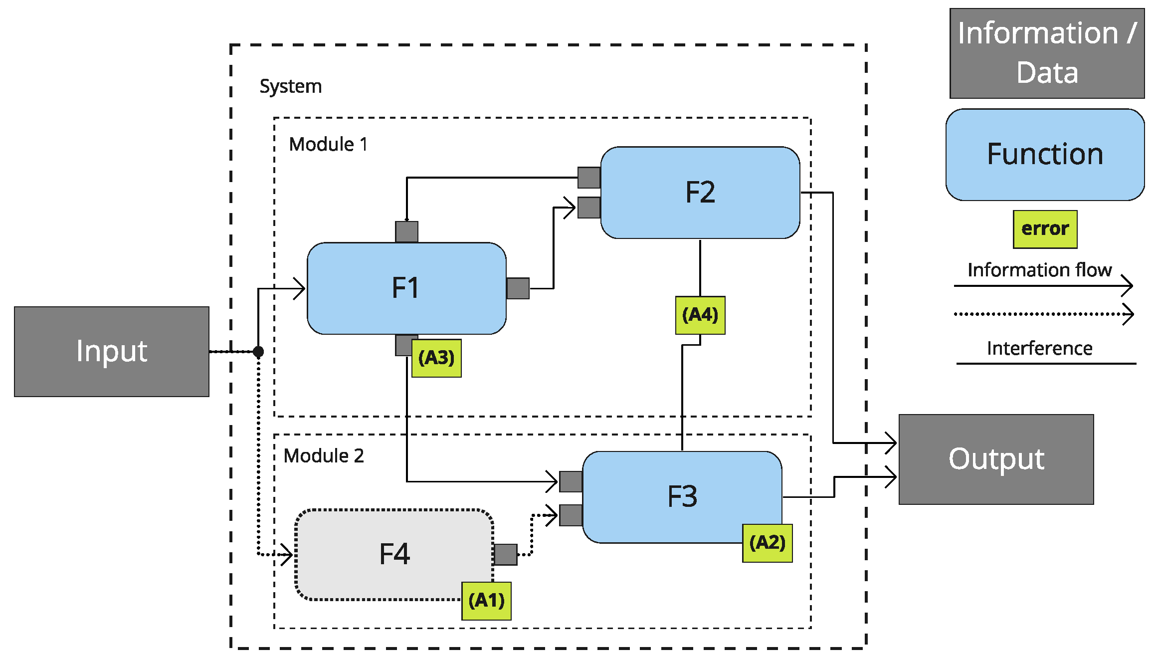
the specified function of the module is not fulfilling the requirements on system level together with the functions of other modules. This is illustrated by a simplified functional architecture of a system with an input and an output in
Figure 2. An error of the specified function means that the implemented function of the module works as specified, but the specification of the function is faulty.
For the case that the second requirement is not fulfilled, one error can simply be that the specified function is not fulfilled by the module. However, this broad generalization is not the aim of this work (e.g., analyzing or even changing the development process of the modules after their functional description in the process). However, testing the module function still serves as a major approval method. Thus, we take the testing procedure of modules into account as a potential uncertainty, because it uses information from the system level to try to falsify the absence of unreasonable risk. Due to this, the second error B leading to the top event of the fault tree is defined such that the specified function of the module is not sufficiently tested.
3.1. Errors Due to Insufficiently Specified Functions
The fault tree for causes derived by error A is shown in
Figure 3. All multiple connections are OR-gates so that we do not use the associated symbol to reduce necessary space and increase readability.
Figure 2 supports the findings of the following branches in the fault tree derived from error A.
In the architecture, errors are assigned to their location, visualized by small boxes, and named by a letter and a number in accordance with the fault tree. The system contains module 1 and module 2, which are containing the functions F1, F2 and F3 that are receiving and sending information, illustrated by arrows.
The function F4 in
Figure 2 is visualized by a gray box to represent a
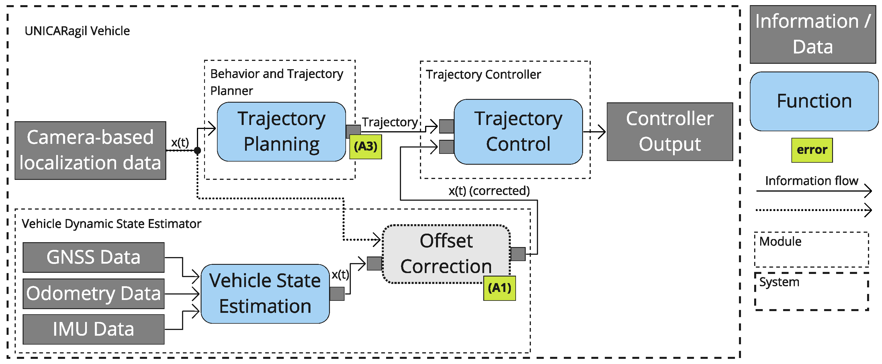
missing function as error A1. This function is not necessarily mandatory to fulfill the overall requirements, the absence of which would be obvious but can be a supporting function that only leads to unreasonable risk in specific scenarios. In UNICAR
agil, we experienced this with the initial absence of the pose offset correction as described by Homolla et al. [
24] which would have led to an increasing control error in cases of inconsistent localization data. The simplified functional architecture of UNICAR
agil showing this exemplary error is illustrated in
Figure 4. In the architecture, the trajectory calculation uses localization data x(t) from a camera-based source as described by [
25] (pp. 1541–1542). The trajectory control uses the localization data x(t) from the vehicle dynamic state estimator module which is based on the sensor data of the global navigation satellite system receiver (NovAtel Inc., Calgary, AB, Canada) (GNSS), odometry and an inertial measurement unit (IMU). The added function offset correction is then eliminating the offset between these two localization data to x(t) (corrected) while maintaining a stable provision of localization data. Reasons for this and further advantages of this architecture are described in [
24].
Error A2 describes a
faulty or incompletely specified function that therefore inhibits the correct function of the system. However, a function may not only be faulty or incomplete but the communication between functions can be an issue due to
faulty, incomplete or inconsistent interface descriptions, described by error A3. One exemplary fault is the inconsistent use of the angle definition that we have also seen for the yaw angle in our project as also shown in
Figure 4. Even though a missing function usually results in missing interfaces for some other functions, only some minor information on an existing interface may either be missing to fulfill the function correctly (missing information about the interface is also an issue for module testing, but will be part of the test process analysis later on).
Interfaces can not only provide the desired information, energy, or material, some may also
interfere undesirably with the function of another function leading to error A4.
Figure 2 shows interference between functions F2 and F3. A possible example of this is the influence of a function F2 to a function F3 that is using the same bus system. When F2 is faulty (e.g., by sending a big amount of faulty data), it may not be safety relevant, depending on its functionality. However, the sent data may jam the bus so that the safety-relevant functionality of F3 is not able to send its data anymore.
These abovementioned general causes for error A serve as a starting point for a more detailed analysis. Such analysis is strongly dependent on the exact development process, which varies widely between products or companies.
3.2. Errors Occurring in Module Tests
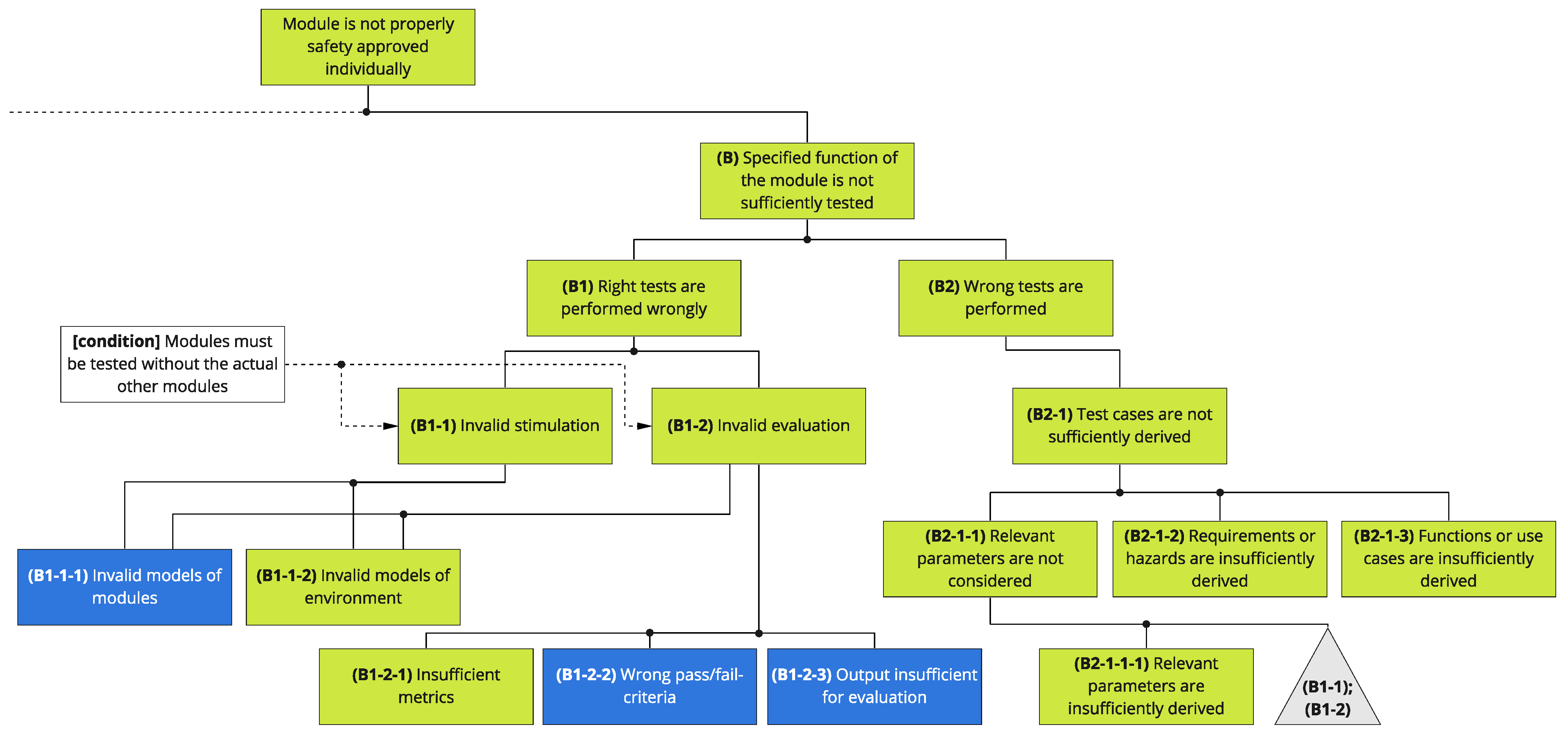
The following section is going to focus on the testing process, but will also reveal possible uncertainty in the development process that causes uncertainty in testing. The error that a module is not sufficiently tested (B) can only be due to right tests that are performed wrongly (B1) or because the wrong tests are performed (B2).
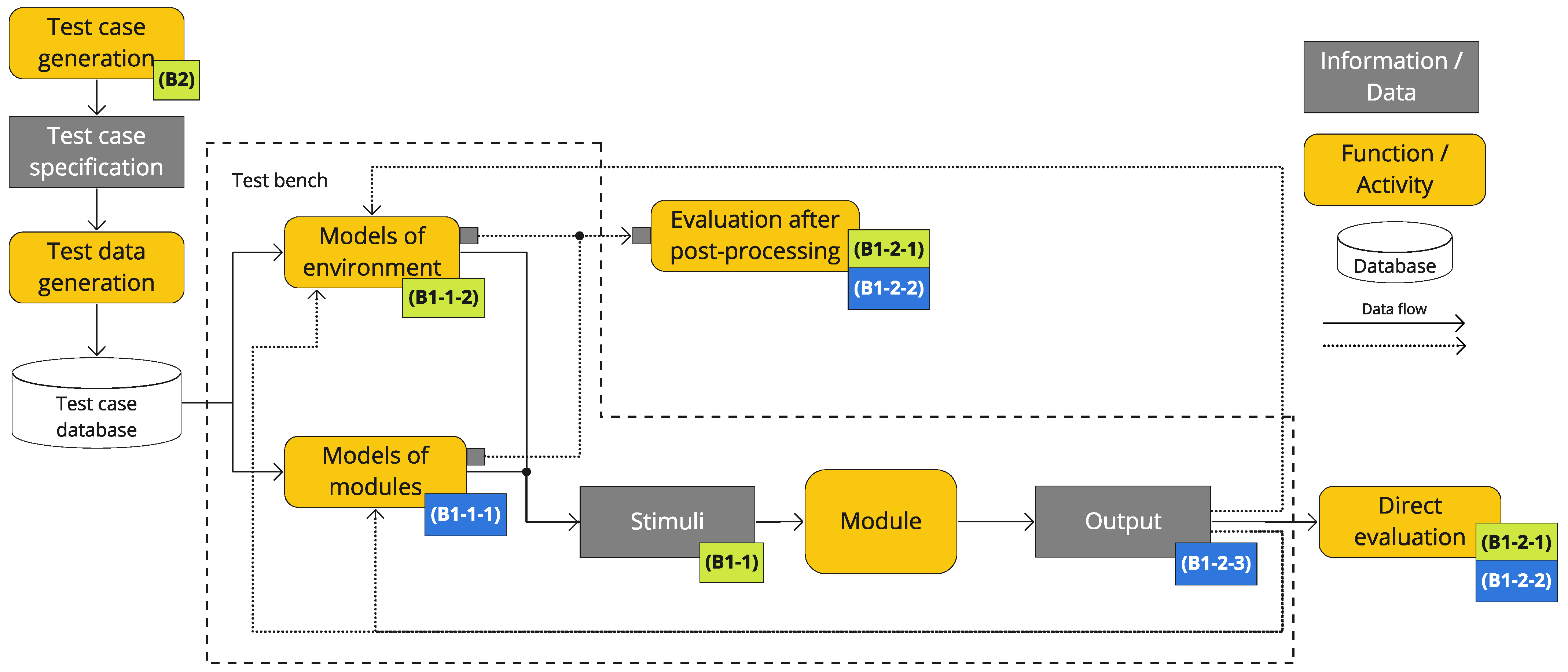
Again, we use a visualization of the possible errors to increase the completeness of the possible errors. For this,
Figure 5 shows a generalized test bench, including the module under test and the specified test environment. The module is assumed to be the same as it is used in the overall system. For some test cases or in earlier development phases, it might be reasonable to use simplified versions of the module under test. However, the same challenges apply on system level and are therefore not considered any further. Additionally, the process of test case development is illustrated. As before, green boxes show the location of the associated errors which are developed by the fault tree. In addition, blue boxes are associated with components or connections that do not have an associated error after the initial fault tree development. In conclusion, the fault tree is extended by revealing possible errors at these remaining components and connections.
3.2.1. Right Tests Are Performed Wrongly
One possible derived error B1-1 for wrongly performed tests is an
invalid stimulation of the module under test.
Figure 5 shows that the stimulation of an object under test is commonly divided into stimulation from other modules of the considered system and the remaining environment. Therefore, we also differ between the errors and derive two errors from B1-1. Firstly, error B1-1-1, which occurs when the
specified and desired stimulation by other modules of the overall system is invalid. Secondly, error B1-1-2, which is caused in the case of the
remaining environment that influences the function of the module as invalid (e.g., the aforementioned thermal energy from other sources). In simulation tests, non-decomposed systems often only require a model of their environment. If they are tested in their original environment (e.g., by unsupervised field operation tests (see also e.g., [
26])), they might not need any models at all. In comparison, decomposed modules possess crucial interfaces to other modules and beyond that, direct or indirect interfaces to the remaining environment. Today, common practices struggle with the validity of such models due to technical or knowledge limitations. Overall, dealing with modular decomposed systems and simulations of connected modules as well as environments (in software or hardware) can increase or decrease the complexity of the validity challenge. Both errors B1-1-1 and B1-1-2 may therefore be caused by module boundaries that do not provide a valid stimulation, e.g., due to technical limitations of simulation practices based on the state of the art.
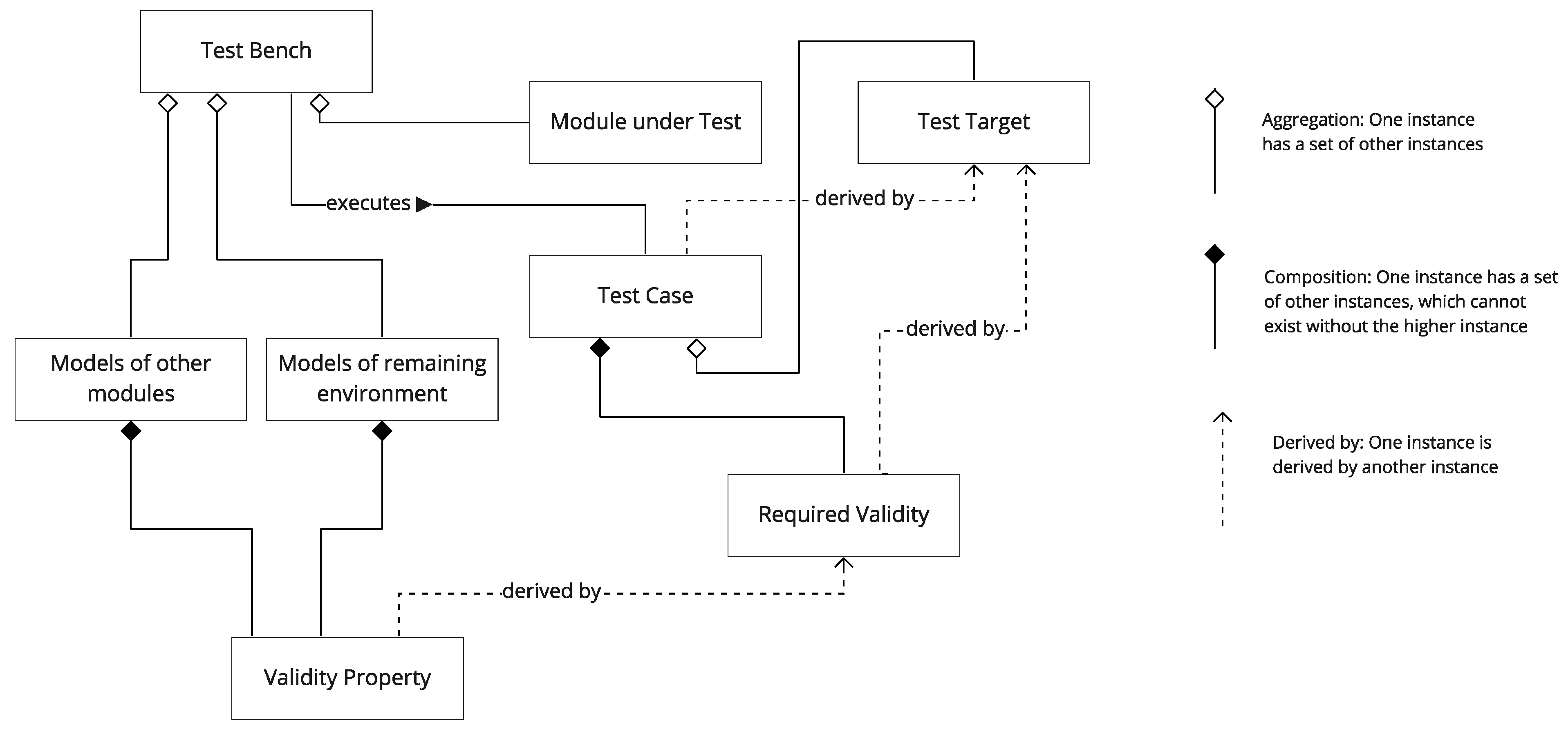
Validity does not mean that a model is representing an exact clone of the simulated entity. The required validity properties of the models in the test bench rather depend on each specific test case [
27]. As illustrated by
Figure 6, in accordance with Steimle et al. [
11], the required validity of the test case is derived by its test targets. If, for example, their purpose is to test the consistency of interfaces or communication between modules, models of participating modules and their functions usually do not require high validity. If on the other side, test targets demand evaluation of the module functionality, highly valid models of the communication might not be necessary for all test cases.
However, it might be crucial to evaluate the influence of time on the implemented behavior of time-critical functions. In conclusion, the connection between test targets and derived test cases needs to be considered even as early as the definition of the module boundaries.
Stimulation can be invalid, but so can the evaluation of its results leading to error B1-2 as invalid evaluation. Evaluation of module tests can be performed directly at the output of the tested modules. Additionally, indirect assessment using models of other modules or the environment and evaluating their outputs represents an alternative. This second way requires models of other modules or the remaining environment, which might again cause the errors B1-1-1 and B1-1-2.
For both ways of evaluation, specific metrics and corresponding pass-/fail criteria (also referred to as evaluation criteria by Steimle et al. [
11] or verification criteria by [
28] (p. 165)) are needed. Hereby, it should be noted that a convenient interface for evaluation depends on the available metrics and their ability to predict the behavior at the system level. This is usually not done directly by the metric, but by evaluating compliance with requirements of investigated modules. In conclusion, module boundaries may be defined so that a valid evaluation is not possible. For example, the evaluation of a decomposed environmental sensor, as depicted by Rosenberger et al. [
29], and its intended functionality is almost impossible by raw sensor data. In that case, decomposing the sensor so that raw sensor data is taken as the output would result in a module boundary that does not allow a valid evaluation. However, in our project, we chose a modular architecture, wherein the controller and its controlled process are not part of the same module. This decision is made because the actuators (dynamic modules), as a part of the controlled process, are intended to work on several platforms, potentially stimulated by different controllers, while the controller (trajectory controller) is parameterized to these different platforms [
7,
30]. Although this procedure is still under research, it allows to approve the safety of said controller individually when valid models of the dynamic modules and the further environment can be built in simulation. Using the actual external module, instead of a representation of it in tests of the module under consideration, cannot be seen as an option for a modular safety approval. The change may mean that a change of the external module requires a new safety approval if it is not clear how the changes influence the tests of the module under consideration. We see this as a boundary condition and categorize it as an invalid stimulation or evaluation. Therefore, it is not introduced as another error.
Figure 5 reveals that the output, respectively, its interface, is not assigned to an error after the fault tree analysis. Regarding the decomposition process, another error B1-2-3 is identified at this point, when the
output is insufficient for evaluation, e.g., when information is missing. In contrast to an insufficient metric (B1-2-1), this case might have a metric, but it is technically not possible to provide the necessary information for this metric. For example, the test target, whether a planner is able to correctly detect traffic regulations, can be reached by using a metric that is simply comparing the actual traffic rules to the ones that the planner detects (e.g., a stop sign demanding to stop the vehicle in front of a defined line). However, a planning algorithm is usually a black box, mainly providing the trajectory as an output. The information about the detected traffic rules can therefore only be estimated indirectly by the given trajectory. This results in a more complex or even impossible required metric for evaluation.
3.2.2. Wrong Tests Are Performed
With error B2-1, we introduce another error type for situations when
test cases are not sufficiently derived for module testing. In regard to the decomposition process, Amersbach and Winner [
31] propose a way to reduce the parameter space of test scenarios by decomposing the system (an automated vehicle) and only considering parameters from its system level that are relevant to each separate decomposed functional layer. Their individual relevance can be specified by experts or, e.g., determined by sensitivity analyses. In order to specify relevance by experts, the performing experts need to obtain enough knowledge about the module’s interfaces, functionalities and implementation. Knowledge about the implementation is important for cases where a parameter on system level
pS1 cannot directly be transferred to the interface of the considered module with a parameter set
pM so that
pS1 ≠
pM applies. When
pS1 influences other parameters
pM that influence the module,
pM(
pS1) applies so that
pS1 needs to be considered in module tests. Missing information at the interfaces is already covered by error A3 in
Section 3.2.1. Amersbach and Winner [
31] provide the example that the difference between a hedge and a wall is not relevant for the functionality of the planner if it only uses the information that both are static objects that cannot be driven through. However, a planner may also use the class of the static objects to calculate a probability that dynamic objects (e.g., pedestrians) can get through these objects. For example, a hedge may have low density or some open parts so that objects can get through while a wall of 2 m height may have a lower probability for another object getting through. Even though the class of an object is no interface specified by the planner, it may be that the planning algorithm (especially one that is based on machine learning) uses other information to classify the object without the direct input of the class. Furthermore, for testing the actual implementation of the planner, timing differences between the detection of a wall and the detection of a hedge may occur. At least the time range that a planner needs to handle should be known for the specification of test cases. In general, this can be seen as hidden knowledge in the given information. This hidden knowledge can be revealed by knowledge about the implementation of the module or by specific testing (e.g., the aforementioned sensitivity analysis).
In our project, we revealed a parameter, which was specified as relevant by experts but does not significantly influence the behavior of the trajectory controller. Simultaneously, another parameter shows high influence which was not specified as relevant beforehand. In a test set with said module, circles with varying radii were driven in simulation. This was done due to the assumption that the controller can be challenged by higher lateral acceleration. However, the more relevant parameter that caused a higher control deviation was the yaw acceleration. Yaw acceleration is caused at the entrance from the previous straight line into the circle where the highest deviation from the planned trajectory can be observed.
Consequently, not only a functional description and knowledge of module implementation is required (as it is for a system as well), but also knowledge about the processing of parameters within the entire modular architecture from system level to module level. This is commonly achieved through interface specifications which provide detailed information about parameters and their possible values. However, for a modular safety approval, even more detailed descriptions become necessary. In order to clarify which information or behavior on system level is causing certain inputs to the individual modules, all transformations in each flow of information need to be defined. Conversely, it requires specification of all system level behavior which is caused by information outputs of modules. This is essentially what metrics (for direct outputs of modules) as well as simulation models of the environment or other modules are supposed to do. We already cover possible errors to this matter by error types B1-1, B1-2 and the following.
With the proposed test methods of ISO 26262, as listed in
Table 1, interfaces, requirements, use cases and possible hazards should be addressed by testing particularly. These tests can be derived from system level information or other information, which has already been derived to module level. Interfaces are generally defined on module level. However, for a sufficient test case generation, not only the technical description of each interface is important, but also specified expectations for its values, their time behavior and possible sequences. This can be derived from information on other modules or the environment. Requirements on system level can be decomposed to the module level with the aid of the functional architecture. Use cases on system level can be decomposed in similar ways so that modular functionalities for each specific use case are formally described. On that basis, requirements for the module level can be derived additionally. Moreover, requirements are derived from the concrete technical design, especially when safety functions are needed due to the chosen design. These requirements do not have a direct connection to system requirements, initially. Still, they do have a connection to the system level through functions or requirements on module level. The same applies to possible hazards that can be identified directly on module level or derived from system to module level. Principally, module tests are derived such that the module-specific causes for the identified hazards are likely to occur. The final test cases which are designed for the system level can finally be broken down to module level as well, similar to use cases or, as called in the automated driving domain, scenarios. While all derived information may be insufficiently derived leading to error types B2-1-1-1, B2-1-2 and B2-1-3, certain parameters may also be neglected due to an invalid stimulation or evaluation. All errors of this chapter are illustrated in the fault tree in
Figure 7.
However, a lot of information that is relevant on system level is not relevant for every single particular module, but only for other specific modules. In UNICARagil, we test the trajectory controller using trajectories that are previously generated based on maneuvers considering the vehicle’s driving capabilities. Analyzing all possible scenarios on system level would only reveal that these are combinations of differently parameterized maneuvers. For example, a scenario wherein the regulations are not clear due to changes to the infrastructure (e.g., multiple traffic signs or lane markings) may be challenging for the environment perception and the planner but not for the controller. Still, an abrupt change of the trajectory needs to be considered in this scenario, which then also needs to be tested on controller level. Driving through road spray is another scenario on system level which could be challenging for module systems of the environment perception. Consequently, for the trajectory planner, this physically interfering factor could result simplified in a reduced range of view. This further leads to fast reaction requirements of the controller to achieve low braking distances or evasion capabilities. In another perspective, spray is a result of wet conditions and therefore correlates with a reduced friction coefficient in comparison to dry conditions. In conclusion, scenarios on system level can be used to derive test cases on module level directly, but need to be categorized to the functionalities of the considered module. Thus, a previously defined functional architecture is mandatory. This results in similar uncertainties as in the test case definition that is based on already decomposed information on module level, considering scenarios on system level may extend test cases generated from information on module level. However, it is likely to cause a less efficient process in comparison to the test case generation by module requirements, functions, or risks.
3.3. Rules to Avoid Errors Due to Decomposition
In order to avoid aforementioned errors, we provide certain rules that can be applied during development and testing. Therefore, each discovered error on the lowest level of the fault tree is used to define a rule, which then helps to avoid this specific error. These rules might serve as a general checklist and are listed in
Table 2. Besides aiming to prevent the error, they also include previously described findings in regard to the validity of simulation models and the required information for test cases.
Covering errors A1 and A2, the first rule R1 demands that module functions in a system fulfill all system requirements. While this alone seems to be trivial, it leads to the overarching recommendation to design functions and requirements traceable from system to module level and vice versa. This is particularly important when single changes of one module create an impact on other modules. All connected and possibly necessary changes then need to be traceable.
The second rule R2 demands a detailed description of the interfaces of each module in all different architectural views to cover error A3. Such a description shall not only contain a technical and a functional perspective as usual but instead cover all possible circumstances of the interface in its intended environment. Consequently, at least a functional description, permitted values, the time behavior and possible sequences, as well as including a failure model of each are mandatory. Failure models, including all probable or even allowed failures, are important for other affiliated modules in order to avoid failures on system level.
Here also, the next rule ties in. Rule R3 demands that all possible conditions of each module are already included in the architectural descriptions. Derived from these specifications, relevant conditions for other modules can be considered in all ensuing development and testing processes.
As a further guideline, rule R4 avoids error A4 by demanding an analysis of possible interferences between modules, which might have been overlooked during the specification of modular architectures. The descriptions demanded by the rules R2 and R3 support this analysis and are supplemented by its results.
For a valid stimulation rule R5, which covers errors B1-1-1 and B1-1-2, demands that the modular architecture provides interfaces that allow a valid representation of other modules and the environment. This leads to the additional need for an early definition of test targets and test cases, which clarify the necessary representations.
In a similar way, rule R6 demands interfaces that allow for a valid evaluation with metrics and associated pass-/fail criteria to cover errors B1-2-1, B1-2-2 and B1-2-3. Thus, they also need to be defined together with the associated test targets and test cases before the final definition of the modular architectures.
Finally, rule R7 covers B2-1-1-1, B2-1-2 and B2-1-3, demanding information on each module level to be traceable to the system level by at least one modular architecture and vice versa. Analogous to traceable requirements in R1, transparent information references are specifically important in order to accomplish sufficient development of test cases.
Yet, not all rules are measurable and thus cannot be verified directly. These rules should be broken down for an actual technical implementation to become verifiable, while others offer as indicators for developers and testers on what to pay attention to. Furthermore, every discovered violation of one of these rules can be taken for improving the applied development and test process. Primarily, the demanded traceability is well measurable but challenging in assessing whether the information at module level is sufficient for a modular safety approval.
5. Conclusions
In this paper, we have shown that the new concept of a modular safety approval requires a structured and specified procedure in development and testing that considers the differences between system and modules. A fault tree analysis together with the analysis of an associated functional architecture and a generalized test bench is presented as a new approach to identify possible errors in modular development projects. Firstly, the system level is compared to the module level in regard to available information and test methods. Resulting conclusions are used to derive errors that may occur during the decomposition of this information for the development and testing of systems, respectively, of its modules with applied decomposition.
Subsequently derived rules for the decomposition process can be broken down into more specific rules or requirements for a specific system with its modules in order to support developers and to become verifiable themselves. Therefore, we provide our findings as a starting point to identify further errors and rules, which assist to reach a successful modular safety approval.
The initial question of why the state of the art does not dispense on system tests yet can be traced back from the described processes according to the state of the art. Industry norms and standards, at least in the automotive industry, explicitly require to perform the safety validation on system level (or for ISO 26262 equivalently seen at the vehicle level). One reason for this is the lack of supervision processes for the development steps of modules. The focus of information aggregation, process control and testing instead still lies on system level. Since the system level provides less uncertainty than lower levels, fewer analyses of uncertainties are required for the safety validation. Still, we expect interest in modular development to increase despite the additional analysis effort. The potential reduction of the enormous testing efforts by a modular safety approval, in which a module can be used for a variety of vehicles and does not require regression testing after modifications of other modules, is key for an economically feasible introduction of automated vehicles. Looking ahead, implementing modular approaches in norms and industry standards might prove to be advantageous for other vehicle functions as well. Finally, modular practices might be particularly beneficial for the automotive supplier industry, enabling them to develop and sell modules without requiring validation on a system level.


