1. Introduction
Magnetic resonant wireless power transmission (MRWPT) is a method that can transmit power farther distances than the conventional WPT [
1]. This method uses an additional resonance phenomenon, thus enabling high efficiency power transmission only at certain resonant frequencies. Because power is transmitted through the alternating magnetic field, if an object that affects the magnetic field is located between the transmitting and receiving coils, it changes the resonant frequency and affects the transmission power and efficiency [
2,
3,
4].
In commercial fields, such as charging of electric vehicles and electronic devices, obstacles such as chassis or cases are often located between transmit/receive coils. There are several studies on the effect on the properties of ferrite core or aluminum plate for shielding in WPT. However, most of the studies on obstacles between coils in WPT have focused on specific materials (Seawater, pipes, etc.) or have discussed the reduction of efficiency and quality factor at fixed operating frequencies [
5,
6,
7,
8,
9]. In addition to enabling power transmission in systems with fixed obstacles, it is also important to restore the system’s output and transmission efficiency when an unknown obstacle is suddenly located [
10,
11,
12]. Due to the characteristics of the MRWPT operating at the resonant frequency, the influence of the obstacle will show various aspects according to its electrical/magnetic properties, but the effect of these properties on the resonant frequency or output power has not been studied.
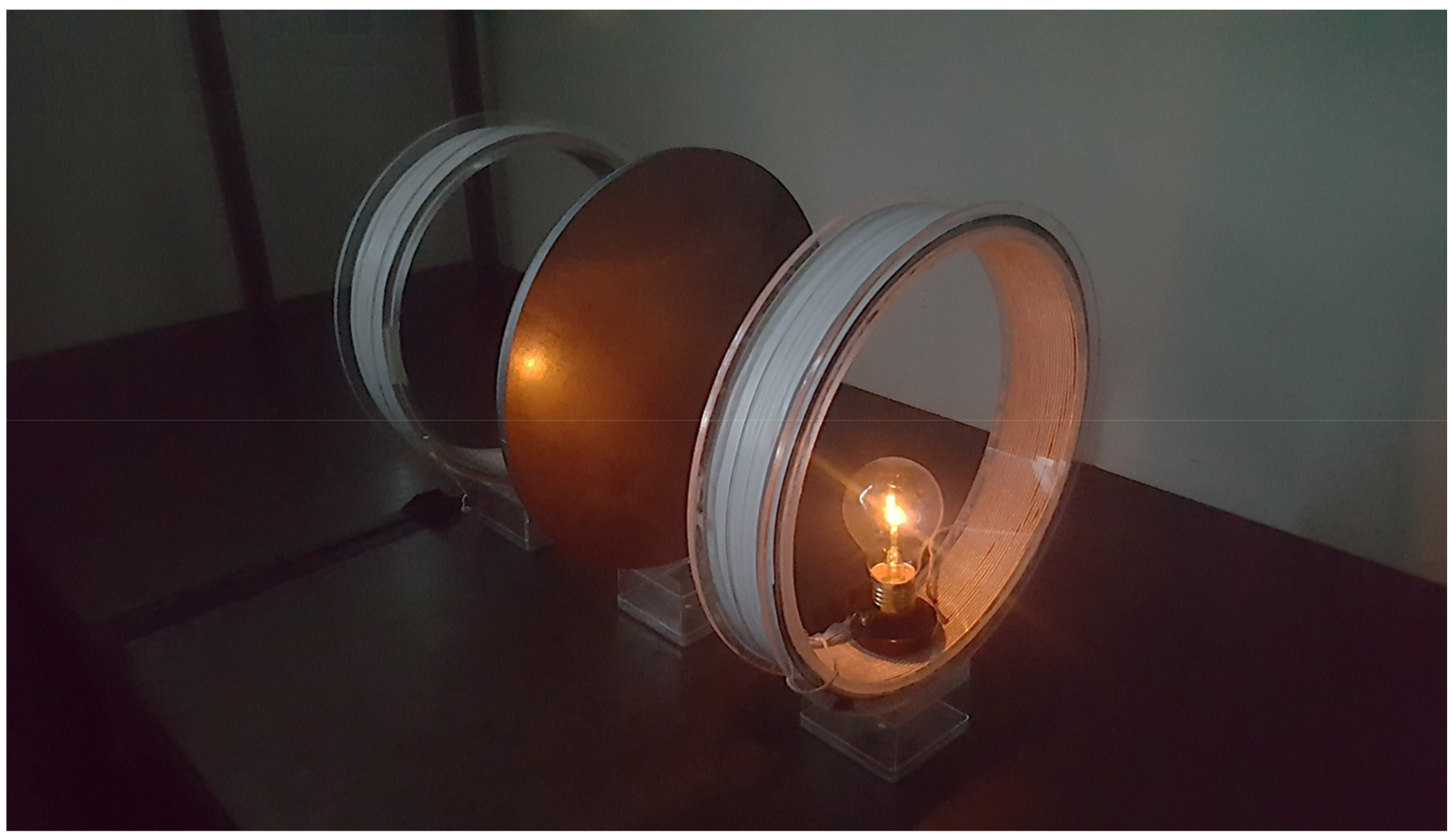
Therefore, in this paper, obstacles with various electromagnetic characteristics, such as magnetic substance and electric conductors, were selected, and the effect of their properties on power transmission was simulated through finite element analysis (FEA). In addition, the method of recovering the reduced power due to obstacles was simulated and verified through actual experiments, as shown in
Figure 1.
2. Types of Electromagnetic Material
The properties of the material affecting magnetic field include magnetic permeability () and electrical conductivity (). An object with permeability is magnetized inside the field and changes the magnitude and shape of the surrounding magnetic field. In contrast, when an object with conductivity is placed in an alternating magnetic field, an eddy current is formed inside the object, which forms a magnetic field in a direction opposite to the applied field. As a result, eddy currents interfere with existing magnetic fields and causing power drop due to ohmic loss.
We selected soft ferrite to investigate the effect of permeability. Ferrite is a ceramic material with high magnetic permeability and low conductivity due to sintering process during the manufacturing. In addition, aluminum was selected as a material having only conductivity without magnetic permeability, and carbon steel (SS400) was selected as a material having both properties. Aluminum is widely used in automobiles because of its low density and good corrosion resistance, and SS400 is a carbon steel widely used for structural purposes. In other words, these two materials are relatively more likely than other materials to be positioned as obstacles in WPT. The value of the properties of these materials are shown in
Table 1.
The effects of these obstacles on power transmission were analyzed by comparison with the case of air (or free space), and other properties (permittivity, density, etc.) that do not significantly affect power transmission were ignored.
3. Simulation of the Influence of Obstacle
A magnetic resonance power transfer system with a resonant frequency of 20 kHz was simulated for analysis. The transmitting and receiving coils are 300 mm in diameter and 40 mm in height, which can transmit power up to 400 mm. Optimal transmission distance is 300 mm, which enables 43 W power to be transmitted with about 60% efficiency.
Each helical coil has 72 turns of 200 strands and has an inductance of 2.59 mH. A capacitor of 24.45 nF has been added for resonance, and the system resonates at a 20 kHz frequency resulting in maximum output and efficiency. The obstacle located between two coils has the same diameter as the coil and a thickness of 10 mm.
Figure 2a shows the equivalent circuit of a typical MRWPT system, where
and
are the self-inductance and resistance of the transmit/receive coil,
is each compensation capacitor, and
is the source/load resistance [
13,
14,
15,
16,
17,
18]. When power is transmitted through free space, the coupling coefficient, k is determined by the geometry of the coil and the transmission distance. Additionally, the coupling between the two coils can be replaced by the T equivalent circuit, as shown in
Figure 2b, and the mutual impedance M is calculated as
and the inductance of each coil becomes
Therefore, if the coupling coefficient and the value of each element are known, the transmission power can be calculated as follows:
where
is the angular frequency, and the total impedance of the transmitting/receiving side
and
are
However, if there is an obstacle affecting the electromagnetic field between the two coils, as shown in
Figure 2c, it is difficult to predict the output power with a circuit equation. Therefore, power transmission was simulated through FEA that can take into account the electromagnetic characteristics and geometry of obstacles.
Figure 2.
Equivalent circuit of the MRWPT system: (a) Power transmission through free space; (b) T equivalent circuit; (c) equivalent circuit with the impedance of the obstacle.
Figure 2.
Equivalent circuit of the MRWPT system: (a) Power transmission through free space; (b) T equivalent circuit; (c) equivalent circuit with the impedance of the obstacle.
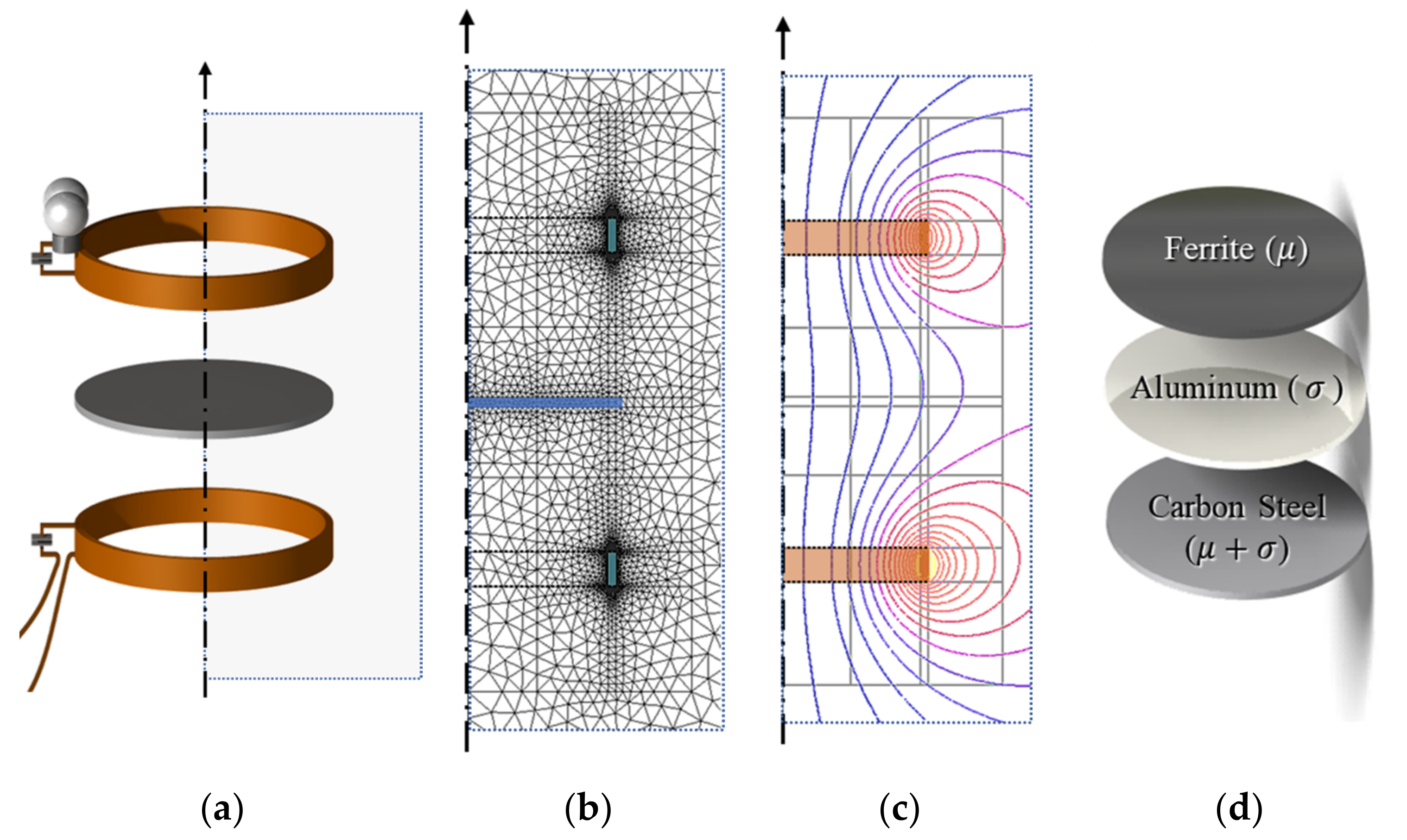
The simulation proceeded at the optimum transmission distance (300 mm), and the obstacle was located in the middle of the two coils (150 mm from each coil). The system was simulated using the commercial FEA software, ‘Flux′ (Ver. 12/G2Elab, Grenoble Alpes University, Grenoble, France), and
Figure 3 shows the 2D and 3D models of the system and obstacle used in the simulation. A steady-state 3D simulation of an AC magnetic field was performed on a model divided into over 300,000 elements to determine the output power versus frequency.
3.1. Influence of Obstacle with Magnetic Permeability
First, the change in resonant frequency and power was simulated when the ferrite, a magnetic material with a permeability, was located between the coils.
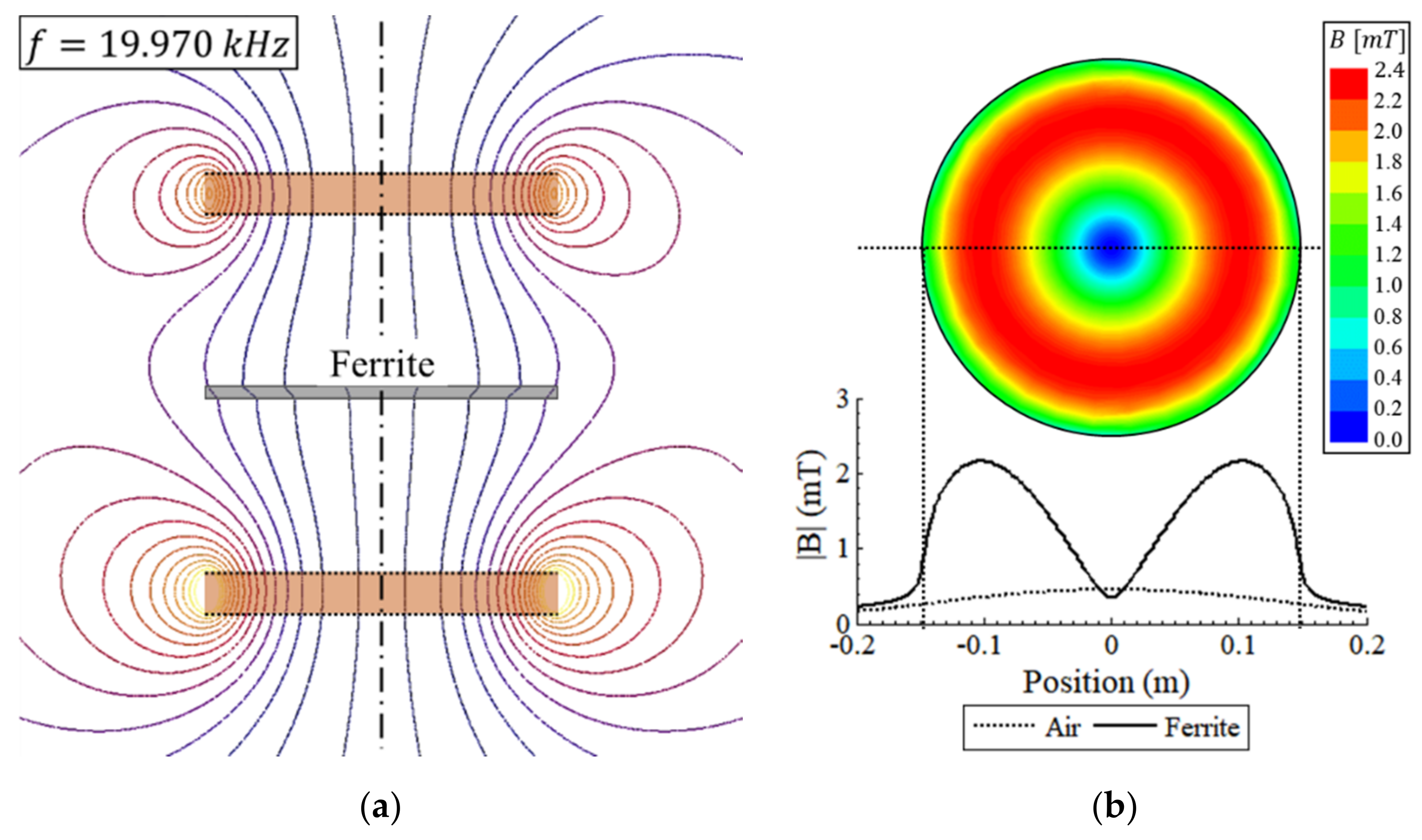
Figure 4a is a simulated magnetic flux line, showing that the magnetic field around the ferrite is attracted to the ferrite. This effect increases the magnetic flux density, B, inside the ferrite compared with the case of air, as shown in
Figure 4b.
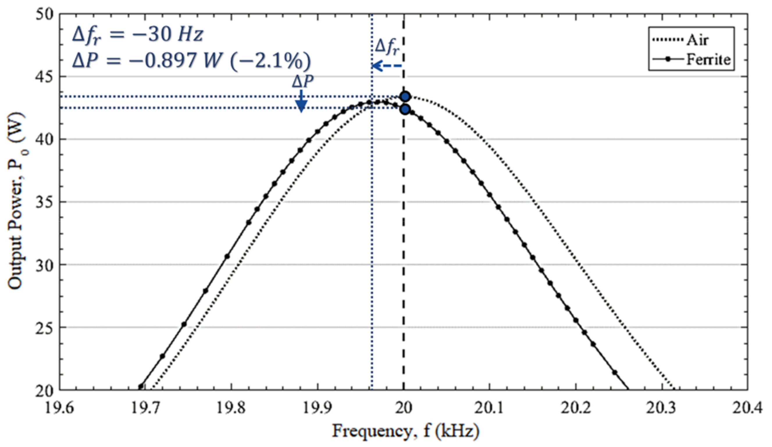
As a result, ferrite lowers the resonant frequency and slightly reduces the output by increasing the inductance of the equivalent circuit. This change is shown in
Figure 5 as a graph of output power versus frequency compared with the case of air. The resonant frequency of the system is reduced by 30 Hz from the original 20 kHz due to the ferrite, and the output is reduced 0.897 W (−2.1%).
3.2. Influence of Obstacle with Electrical Conductivity
Under the same conditions, the case where aluminum, a conductor with electrical conductivity, is located between two coils was simulated.
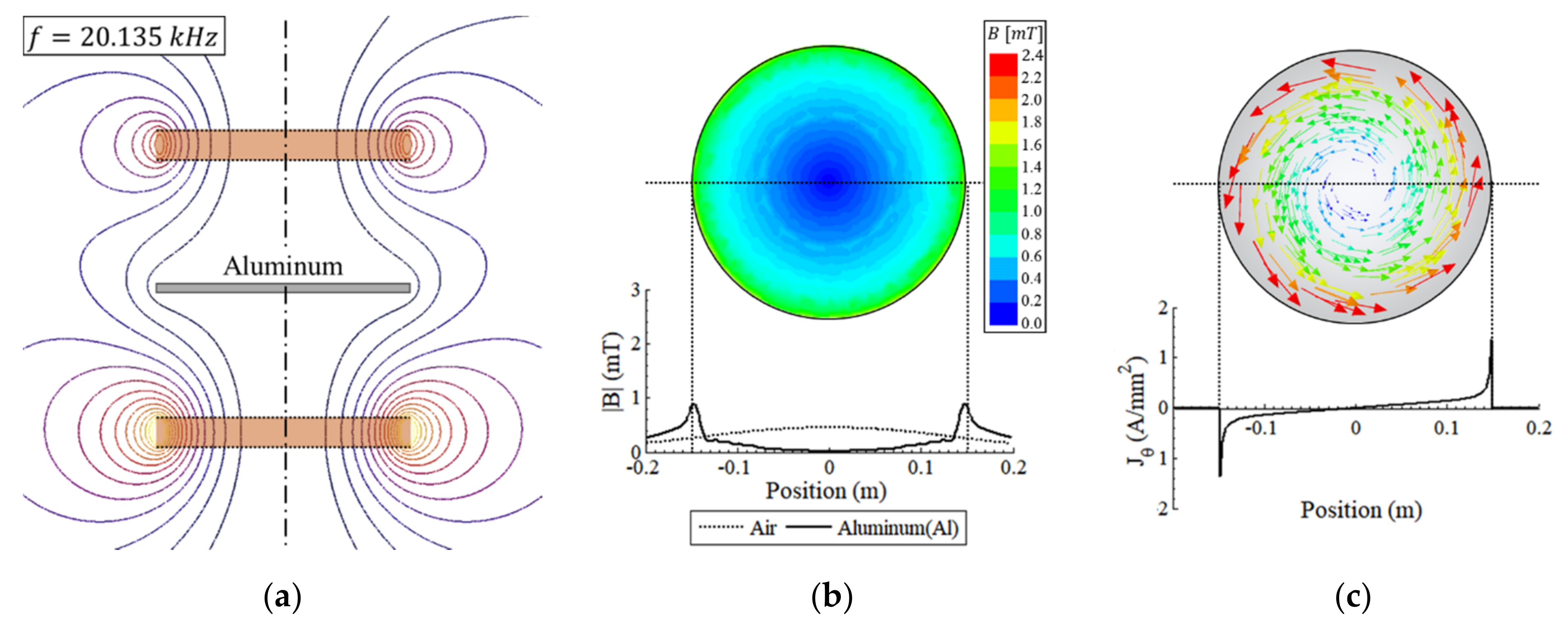
Figure 6a is a simulated flux line, showing that shows that aluminum has the effect of repelling the surrounding magnetic field.
Figure 6b shows the magnetic flux density, which is decreased compared to the case of ferrite. This phenomenon is caused by the rotating eddy current formed inside the conductor due to the time-varying magnetic field as shown in
Figure 6c. This eddy current has a rotational direction opposite to that of the applied current, so it creates a magnetic field that interferes with the previously applied magnetic field. The magnitude of the eddy current is proportional to the strength of the magnetic field, frequency and conductivity of material, but it is difficult to accurately predict its value due to the skin effect.
The interference of the magnetic field by the eddy current weakens the coupling between the two coils. This means that
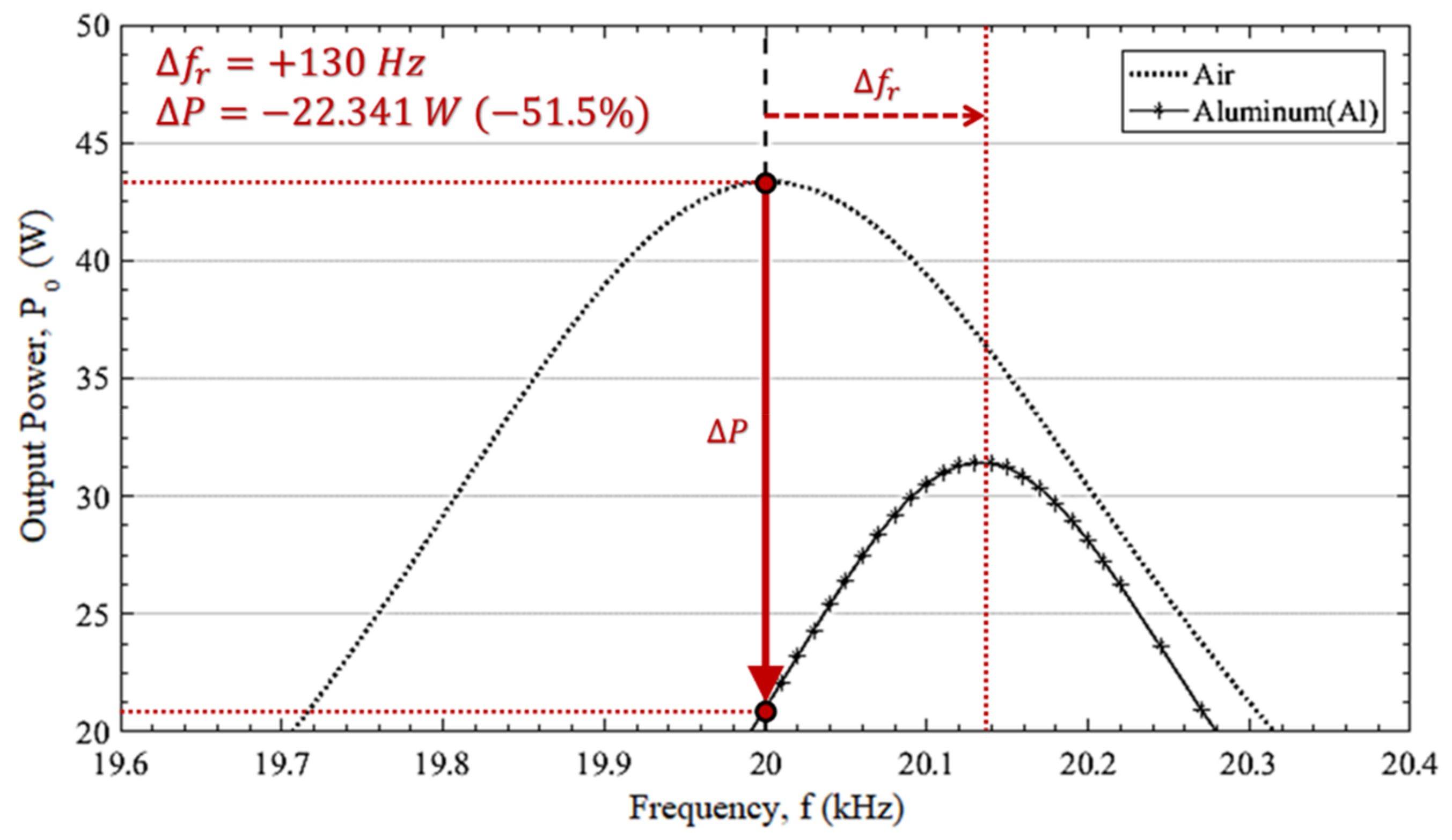
k in Equation (1) decreases and, accordingly, the output power also decreases as if the distance between the two coils has increased. In addition, this effect increases the resonant frequency by reducing the self-inductance and reduces the system output power due to the ohmic losses of the eddy currents. The result is shown in
Figure 7 as a graph of output power versus frequency compared with the case without obstacle. The resonant frequency of the system is increased by 130 Hz from the original 20 kHz due to the aluminum, and the output is reduced by 22.341 W (−51.5%).
3.3. Influence of Obstacle with Both Permeability and Conductivity
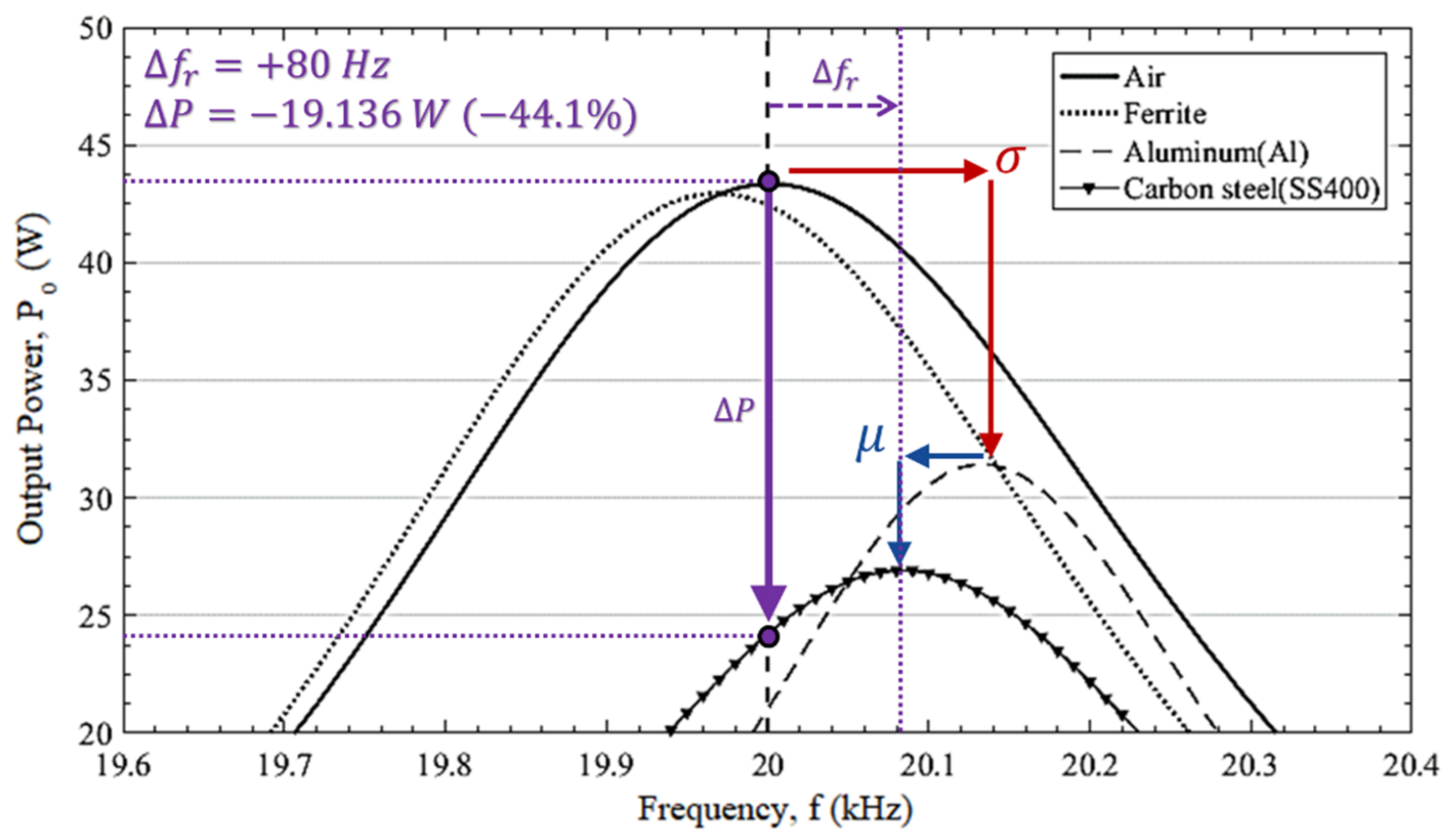
To analyze the effect of an obstacle with both magnetic permeability and conductivity, the same simulation was performed using carbon steel, SS400. The results shown in
Figure 8 show the combined effects of two properties, magnetic permeability (blue arrow) and electric conductivity (red arrow). Compared to the case of aluminum, the increased inductance due to the additional permeability lowers the resonance frequency, and the increased eddy current due to the stronger magnetic field lowered the output power.
3.4. Summary
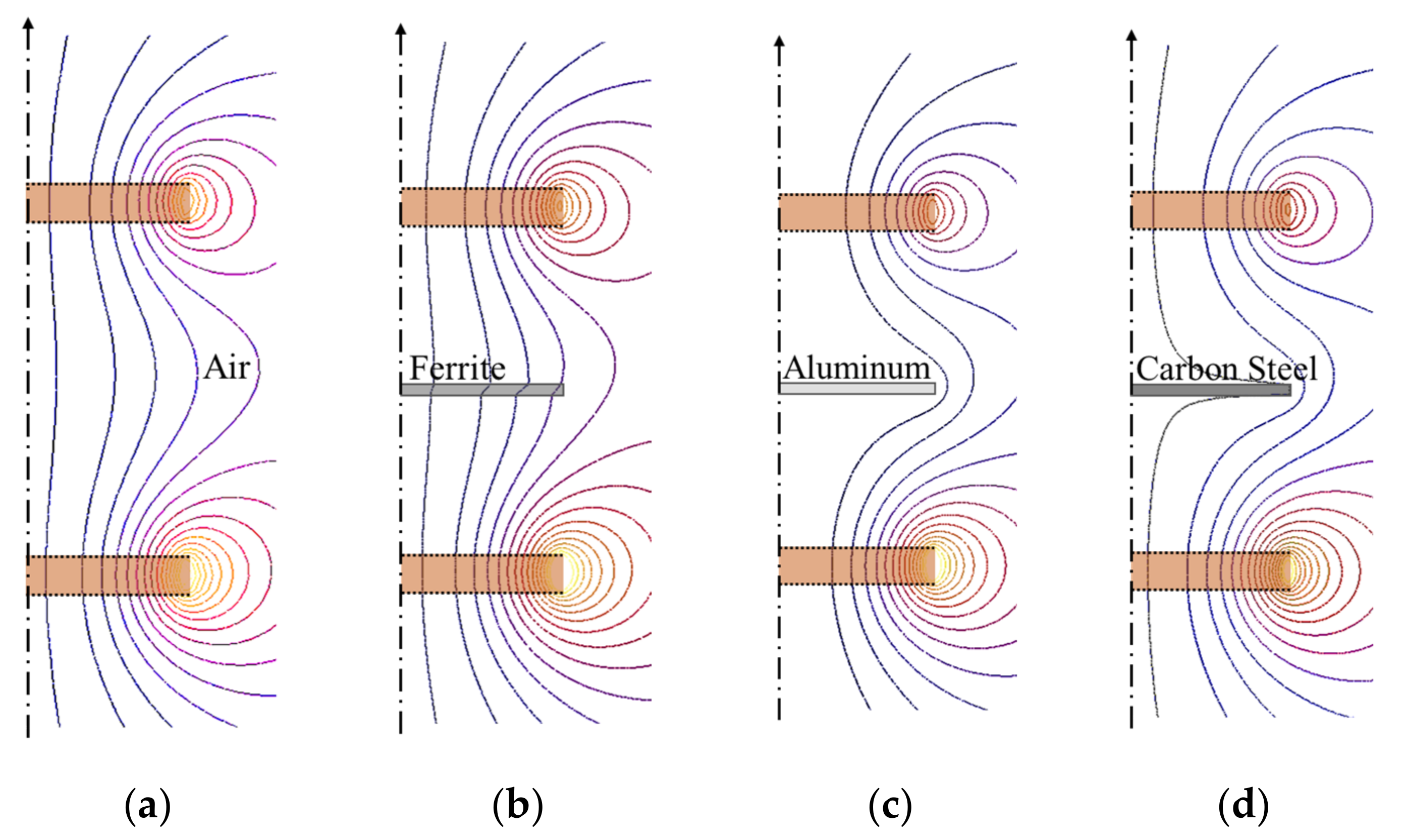
The magnetic flux line according to the obstacles are shown in
Figure 9. There is a clear difference in the path of the magnetic flux depending on the properties of each material.
A material with magnetic permeability become magnetized in response to an applied magnetic field and attracts the path of the external magnetic field. This effect increases the inductance of the overall system, resulting in a reduction in the resonant frequency. In contrast, a material with electrical conductivity forms eddy currents inside and pushes out the magnetic field. This not only increases the resonant frequency by reducing the inductance of the system, but also induces eddy current loss.
In the case of carbon steel, which has both permeability and conductivity, the effects of both properties are combined. For the shift of the resonant frequency, the effect of conductivity is dominant, because the weakening of the coupling due to the eddy current has a greater effect than the change in inductance. Because the two effects on the resonant frequency are opposite to each other, they can be balanced in certain situations. Although it is a rare property in practice, the resonant frequency did not shift when the relative permeability was and the conductivity was in the simulation.
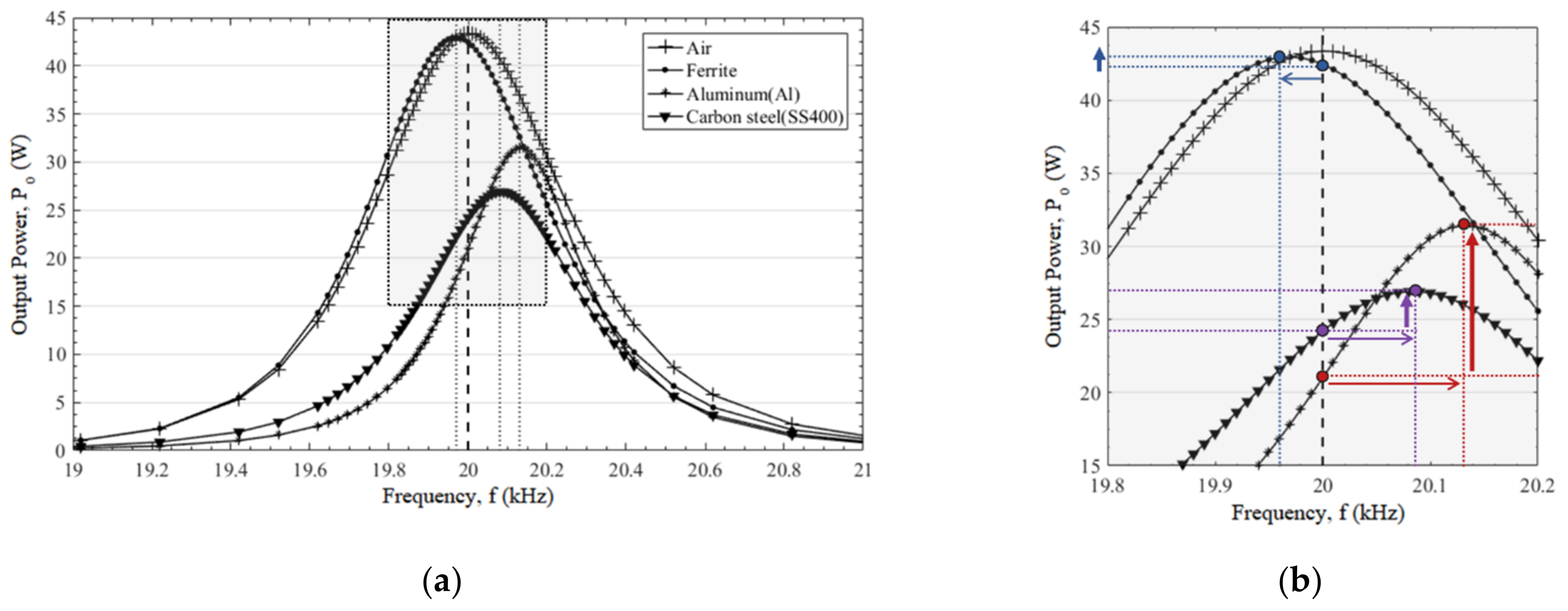
For all cases, a graph of output power versus frequency is shown in
Figure 10a,b. In this situation, if the input of the original resonance frequency of 20 kHz is continuously applied, the output of the system is decreased. Through these simulation results, the electromagnetic properties of unidentified objects added between coils can be estimated by observing the change of the output. Furthermore, it is possible to recover a part of reduced output by adjusting the frequency of the input source to suit the added object.
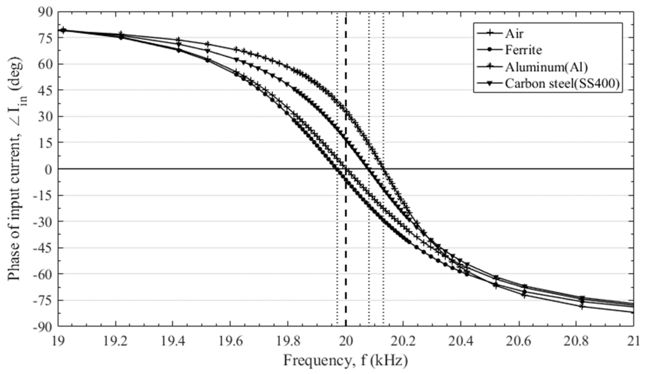
MRWPT uses the principle that the reactance of the input terminal approaches zero at the resonance frequency and thus the output becomes maximum. Accordingly, as shown in
Figure 11, the phase of the input current becomes 0 at the resonant frequency, and has positive/negative values at lower/higher frequencies, respectively. Therefore, when the resonance point is changed due to an obstacle, the changed resonance frequency can be obtained by measuring the phase of the input current.
Figure 10b shows the process of adjusting the frequency through this method, and the reduced power and recovered power are shown in
Table 2.
In a system with a higher resonant frequency, it is expected that the amount of reduction and recovery of the output power will be greater due to the larger quality factor and more eddy currents.
4. Experimental Verification
To verify these results, an actual magnetic resonant WPT system was constructed and tested under the same conditions.
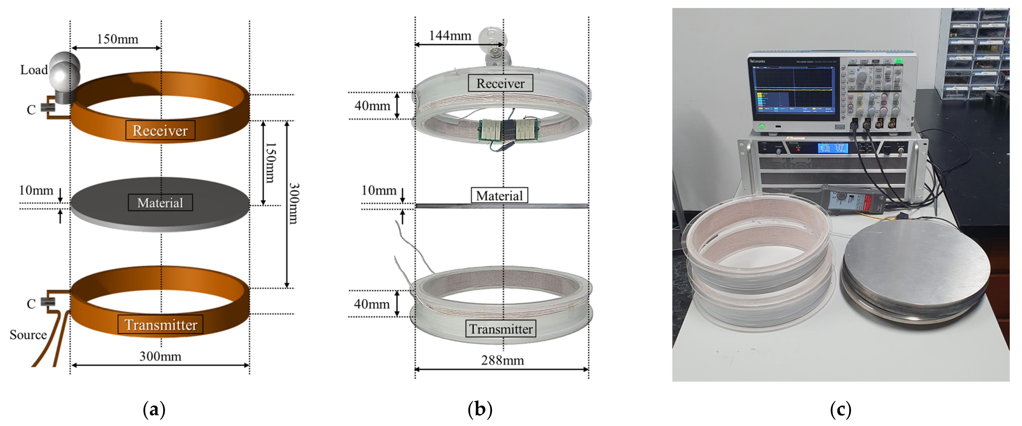
Figure 12a,b shows the model for the actual experiment compared with the simulation model, and
Figure 12c shows the equipment and three obstacles used in the experiment. Detailed specifications of the model for experimental validation are summarized in
Table 3.
The coils and obstacles were arranged as shown in
Figure 1, and the power supply applied a sinusoidal voltage of variable frequency to the transmitting coil. Thereafter, the output power was calculated by measuring the current of the 25 ohm resistive load on the receiving coil side.
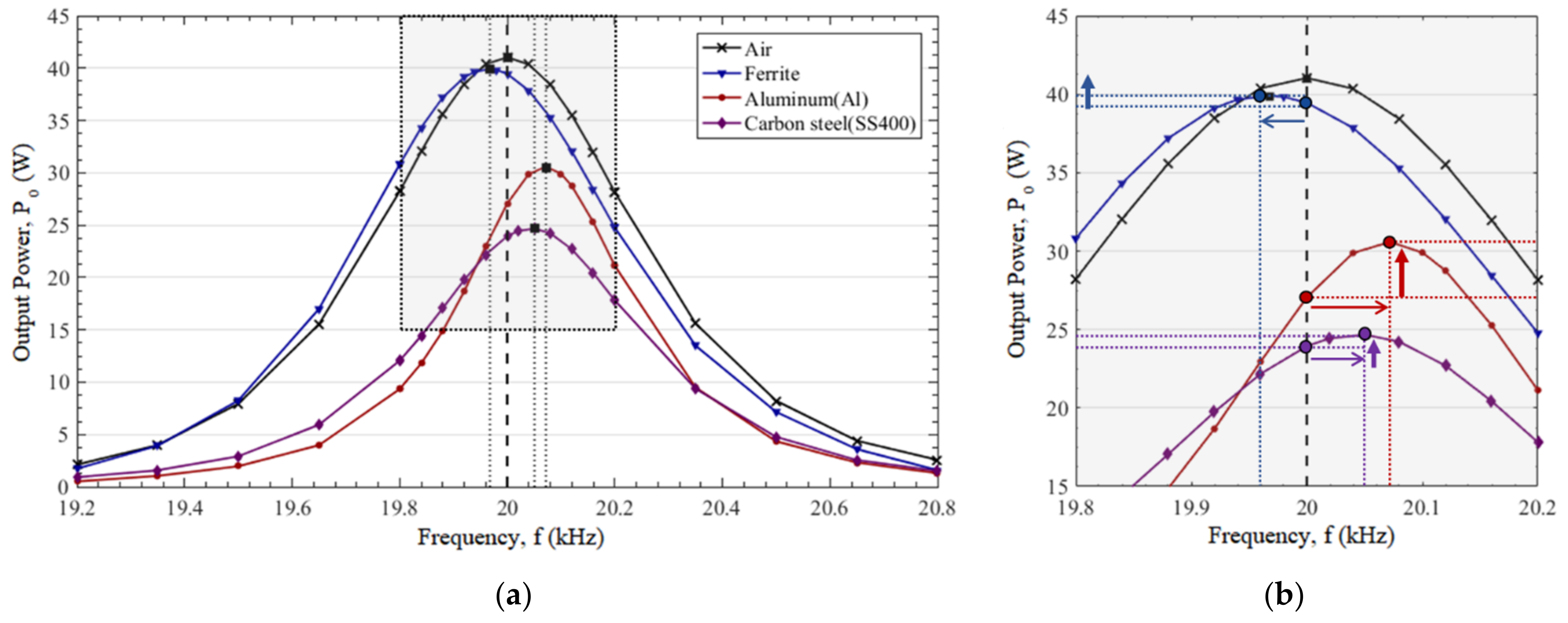
Figure 13 is a graph of the output power versus frequency when each obstacle is located between two coils, and experimental results are very similar to the simulation results in
Figure 10.
The measured values of the output power and resonant frequency are not exactly the same as those of the simulation. This is because the actual obstacles do not have their ideal material properties and non-linear characteristics such as magnetic hysteresis were not considered in the simulation.
The output power of the system, which was 40.98 W, has been reduced to 39.431 W (−3.8%), 26.663 W (−34.9%), and 23.81 W (−41.9%), respectively, at an original resonant frequency of 20 kHz. As in the simulation, a certain amount of reduced output power can be recovered by adjusting the input frequency to changed resonant frequencies, and the amount of the reduced and recovered output is summarized in
Table 4.
5. Conclusions
In this paper, the effects of the obstacle placed between two coils of the MRWPT system on the power transmission were analyzed according to their magnetic/electric properties. Ferrite, aluminum, and carbon steel were selected as obstacles, and the effect on the WPT system was analyzed through finite element simulations and actual experiments.
A magnetic material with a permeability lowers the resonant frequency and slightly reduces the output power. Conversely, conductors with electrical conductivity have internal eddy currents that increase the resonant frequency and reduce the output power considerably. In addition, material with both properties, permeability and conductivity, shows the combined effects of each property.
From these results, the magnetic/electric properties of the unidentified electromagnetic material located between the coils can be estimated. Moreover, a part of the output power reduced by the obstacle can be recovered through frequency adjustment. The changed resonance frequency can be found by measuring the phase of the input current. For example, in the case of aluminum, the phase of the input current at the original resonant frequency appears as a positive value. Accordingly, by increasing the frequency until the phase of input current becomes zero, the changed resonance point can be found. The experimental results showed that adjusting the frequency can restore the output power of 3.868 W, which is 27% of the 14.32 W reduced by aluminum.
These results suggest a way to recover the output power reduction due to an obstacle in a MRWPT system, such as a chassis in car charging, but further studies on the effect of obstacle size and location are needed for accurate prediction of changed resonant frequency.
Author Contributions
Conceptualization, H.-Y.L. and G.-S.P.; data curation, H.-Y.L.; investigation, H.-Y.L.; methodology, H.-Y.L. and S.-H.I.; supervision, S.-H.I. and G.-S.P.; visualization, H.-Y.L.; writing—original draft, H.-Y.L.; writing—review and editing, H.-Y.L. and G.-S.P. All authors have read and agreed to the published version of the manuscript.
Funding
This research was supported by Basic Science Research Program through the National Research Foundation of Korea (NRF) funded by the Ministry of Education (2020R1I1A307275312).
Institutional Review Board Statement
Not applicable.
Informed Consent Statement
Not applicable.
Data Availability Statement
Not applicable.
Conflicts of Interest
The authors declare no conflict of interest.
References
- Kurs, A.; Karalis, A.; Moffatt, R.; Joannopoulos, J.D.; Fisher, P.; Soljacic, M. Wireless power transfer via strongly coupled magnetic resonances. Science 2007, 317, 83–86. [Google Scholar] [CrossRef] [PubMed]
- Jonah, O.; Georgakopoulos, S.V. Wireless Power Transfer in Concrete via Strongly Coupled Magnetic Resonance. IEEE Trans. Antennas Propag. 2013, 61, 1378–1384. [Google Scholar] [CrossRef]
- Chu, I.C.; Jeong, J. Characteristics of Shield Materials for Wireless Power Transfer. J. Magn. 2014, 19, 291–294. [Google Scholar] [CrossRef][Green Version]
- Ahmad, A.; Alam, M.S. Magnetic Analysis of Copper Coil Power Pad with Ferrite Core for Wireless Charging Application. Trans. Electr. Electron. Mater. 2019, 20, 165–173. [Google Scholar] [CrossRef]
- Zhang, P.C.; Yang, Q.X.; Zhang, X.; Li, Y.; Li, Y.J. Comparative Study of Metal Obstacle Variations in Disturbing Wireless Power Transmission System. IEEE Trans. Magn. 2017, 53, 1–4. [Google Scholar] [CrossRef]
- Kim, S.; Jung, D.H.; Kim, J.J.; Bae, B.; Kong, S.; Song, C.; Kim, J. Modeling of Electromagnetic Interference Shielding Materials in Wireless Power Transfer for Board-to-Board Level Interconnections. In Proceedings of the 2014 IEEE Wireless Power Transfer Conference, Jeju, Korea, 8–9 May 2014; pp. 273–276. [Google Scholar] [CrossRef]
- Mahmud, M.H.; Elmahmoud, W.; Barzegaran, M.R.; Brake, N. Efficient Wireless Power Charging of Electric Vehicle by Modifying the Magnetic Characteristics of the Transmitting Medium. IEEE Trans. Magn. 2017, 53, 1–5. [Google Scholar] [CrossRef]
- Liu, G.C.; Mrad, N.Z.; Xiao, G.; Li, Z.Z.; Ban, D.Y. Metallic Environmental Effect on RF-Based Energy Transmission. IEEE Antennas Wirel. Propag. Lett. 2012, 11, 925–928. [Google Scholar] [CrossRef]
- Li, S.Q.; Mi, C.C. Wireless Power Transfer for Electric Vehicle Applications. IEEE J. Emerg. Sel. Top. Power Electron. 2015, 3, 4–17. [Google Scholar] [CrossRef]
- Ahmad, A.; Alam, M.S.; Rafat, Y.; Shariff, S.M.; Al-Saidan, I.S.; Chabaan, R.C. Foreign Object Debris Detection and Automatic Elimination for Autonomous Electric Vehicles Wireless Charging Application. SAE Int. J. Electrified Veh. 2020, 9, 93–110. [Google Scholar] [CrossRef]
- Xia, J.L.; Yuan, X.M.; Li, J.; Lu, S.Z.; Cui, X.X.; Li, S.Q.; Fernandez-Ramirez, L.M. Foreign Object Detection for Electric Vehicle Wireless Charging. Electronics 2020, 9, 805. [Google Scholar] [CrossRef]
- Tang, X.N.; Dai, Y.; Ma, Y.H.; Ren, B.Y. Method for metal foreign object detection in wireless charging system of electric vehicle. Sens. Rev. 2021, 41, 57–64. [Google Scholar] [CrossRef]
- Kawamura, A.; Kim, T.W. Proposed Equivalent Circuit and Parameter Identification Method for Electro-Magnetic Resonance Based Wireless Power Transfer. J. Electr. Eng. Technol. 2013, 8, 799–807. [Google Scholar] [CrossRef][Green Version]
- Kim, J.-G.; Wei, G.; Kim, M.-H.; Jong, J.-Y.; Zhu, C. A Comprehensive Study on Composite Resonant Circuit-Based Wireless Power Transfer Systems. IEEE Trans. Ind. Electron. 2018, 65, 4670–4680. [Google Scholar] [CrossRef]
- Xie, X.; Xie, C.; Li, L. Wireless Power Transfer to Multiple Loads over a Long Distance with Load-Independent Constant-Current or Constant-Voltage Output. IEEE Trans. Transp. Electrif. 2020, 6, 935–947. [Google Scholar] [CrossRef]
- Desmoort, A.; Deblecker, O.; De Greve, Z. Active Rectification for the Optimal Command of Bidirectional Resonant Wireless Power Transfer Robust to Severe Circuit Parameters Deviations. IEEE Trans. Ind. Appl. 2020, 56, 1640–1648. [Google Scholar] [CrossRef]
- Yeo, T.-D.; Kwon, D.; Khang, S.-T.; Yu, J.-W. Design of Maximum Efficiency Tracking Control Scheme for Closed-Loop Wireless Power Charging System Employing Series Resonant Tank. IEEE Trans. Power Electron. 2017, 32, 471–478. [Google Scholar] [CrossRef]
- Onar, O.C.; Chinthavali, M.; Campbell, S.L.; Seiber, L.E.; White, C.P. Vehicular Integration of Wireless Power Transfer Systems and Hardware Interoperability Case Studies. IEEE Trans. Ind. Appl. 2019, 55, 5223–5234. [Google Scholar] [CrossRef]
Figure 1.
Magnetic resonant wireless power transmission (MRWPT) system with obstacle.
Figure 1.
Magnetic resonant wireless power transmission (MRWPT) system with obstacle.
Figure 3.
Configuration of simulation: (a) 3D model; (b) meshes in 2D FEA; (c) magnetic flux lines (in the case of air); (d) obstacles (ferrite, aluminum, carbon steel).
Figure 3.
Configuration of simulation: (a) 3D model; (b) meshes in 2D FEA; (c) magnetic flux lines (in the case of air); (d) obstacles (ferrite, aluminum, carbon steel).
Figure 4.
Influence of the obstacle with permeability (ferrite) at resonant frequency: (a) Magnetic flux line; (b) flux density inside the obstacle.
Figure 4.
Influence of the obstacle with permeability (ferrite) at resonant frequency: (a) Magnetic flux line; (b) flux density inside the obstacle.
Figure 5.
Changes in resonance frequency and output power when ferrite is placed between coils.
Figure 5.
Changes in resonance frequency and output power when ferrite is placed between coils.
Figure 6.
Influence of the obstacle with conductivity (aluminum) at resonant frequency: (a) Magnetic flux line; (b) flux density inside the obstacle; (c) eddy current inside the obstacle.
Figure 6.
Influence of the obstacle with conductivity (aluminum) at resonant frequency: (a) Magnetic flux line; (b) flux density inside the obstacle; (c) eddy current inside the obstacle.
Figure 7.
Changes in resonance frequency and output power when aluminum is placed between two coils.
Figure 7.
Changes in resonance frequency and output power when aluminum is placed between two coils.
Figure 8.
Changes in resonance frequency and output power when carbon steel is placed between two coils.
Figure 8.
Changes in resonance frequency and output power when carbon steel is placed between two coils.
Figure 9.
The shape of the magnetic flux lines when each obstacle is placed between two coils: (a) Air; (b) ferrite; (c) aluminum; (d) carbon steel.
Figure 9.
The shape of the magnetic flux lines when each obstacle is placed between two coils: (a) Air; (b) ferrite; (c) aluminum; (d) carbon steel.
Figure 10.
Simulation results when each obstacle is placed between two coils: (a) Output power versus frequency; (b) output power recovery through frequency adjustment.
Figure 10.
Simulation results when each obstacle is placed between two coils: (a) Output power versus frequency; (b) output power recovery through frequency adjustment.
Figure 11.
Simulation result of the phase of input current according to frequency when each obstacle is placed between two coils.
Figure 11.
Simulation result of the phase of input current according to frequency when each obstacle is placed between two coils.
Figure 12.
Configuration of the MRWPT system with an obstacle: (a) FEA simulation model; (b) actual system for experimental verification; (c) equipment and obstacles used in the experiment.
Figure 12.
Configuration of the MRWPT system with an obstacle: (a) FEA simulation model; (b) actual system for experimental verification; (c) equipment and obstacles used in the experiment.
Figure 13.
Experimental results of the output power versus frequency when each obstacle is placed between two coils.
Figure 13.
Experimental results of the output power versus frequency when each obstacle is placed between two coils.
Table 1.
Material and electromagnetic properties of obstacles.
Table 1.
Material and electromagnetic properties of obstacles.
| Material (Type) | Magnetic Property |
|---|
Relative
| Conductivity,
|
|---|
| Air (Free space) | 1 | - |
| Ferrite (PC40) | 2200 | - |
| Aluminum (1100) | 1 | |
| Carbon steel (SS400) | 2000 | |
Table 2.
Recovering reduced output power in simulation.
Table 2.
Recovering reduced output power in simulation.
| Material | Influence of Obstacle | Frequency Adjustment | Restored
Power | Recovery
Rate |
|---|
| | | | | |
|---|
| Air | 20.00 | 43.352 | - | - | - | - | - | - |
| Ferrite | 20.00 | 42.455 | | 19.97 | 42.949 | | 0.494 | 55.1 |
| Aluminum | 20.00 | 21.011 | | 20.13 | 31.431 | | 10.420 | 46.6 |
| Carbon steel | 20.00 | 24.216 | | 20.08 | 26.912 | | 2.696 | 14.1 |
Table 3.
Specifications of the model for experimental verification.
Table 3.
Specifications of the model for experimental verification.
| Specification | Value |
|---|
| Coil diameter/height | 288 mm/40 mm |
| Input | 28 Vrms |
| L/C | 2.549 mH/24.845 nF |
| Resonant frequency | 20 kHz |
| Transmission distance | 300 mm |
| Material type | Ferrite, aluminum, carbon steel |
| Material diameter/thickness | 288 mm/10 mm |
Table 4.
Recovering reduced output power in experiment.
Table 4.
Recovering reduced output power in experiment.
| Material | Influence of Obstacle | Frequency Adjustment | Restored
Power | Recovery
Rate |
|---|
| | | | | |
|---|
| Air | 20.00 | 40.980 | - | - | - | - | - | - |
| Ferrite | 20.00 | 39.431 | | 19.97 | 39.869 | | 0.438 | 28.3 |
| Aluminum | 20.00 | 26.663 | | 20.07 | 30.531 | | 3.868 | 27.0 |
| Carbon steel | 20.00 | 23.810 | | 20.05 | 24.677 | | 0.867 | 5.0 |
| Publisher’s Note: MDPI stays neutral with regard to jurisdictional claims in published maps and institutional affiliations. |
© 2021 by the authors. Licensee MDPI, Basel, Switzerland. This article is an open access article distributed under the terms and conditions of the Creative Commons Attribution (CC BY) license (https://creativecommons.org/licenses/by/4.0/).

