Abstract
An integrated membrane distillation (MD) flowsheet, consisting of direct contact membrane distillation (DCMD) and vacuum membrane distillation (VMD) units, was proposed and analysed in terms of thermal performance and water recovery factor, for the first time. The same lab-scale membrane module (40 cm2) was used for carrying out experiments of DCMD and VMD at fixed feed operating conditions (deionised water at 230 L/h and ~40 °C) while working at the permeate side with deionised water at 18 °C and with a vacuum of 20 mbar for the DCMD and the VMD configuration, respectively. Based on experimental data obtained on the single modules, calculations of the permeate production, the specific thermal energy consumption (STEC) and the gained output ratio (GOR) were carried out for both single and integrated units. Moreover, the calculations were also made for a flow sheet consisting of two DCMD units in series, representing the “traditional” way in which more units of the same MD configuration are combined to enhance the water recovery factor. A significant improvement of the thermal performance (lower STEC and higher GOR) was obtained with the integrated DCMD–VMD flowsheet with respect to the DCMD units operating in series. The integration of DCMD with VMD also led to a higher permeate production and productivity/size (PS) ratio, a metric defined to compare plants in terms of the process intensification strategy.
1. Introduction
The potential of membrane distillation has been successfully investigated in different fields of industrial interest, such as wastewater treatment, desalination, agro-food and beverage, and biomedical applications [1,2,3,4,5,6,7]. MD is able to well reject all non-volatile compounds contained into the water stream to be treated, thanks to the fact that water is not removed through the membrane as liquid, but as vapor. More specifically, the aqueous feed is in contact at atmospheric pressure with one side of a microporous hydrophobic membrane and it is not allowed to pass through the membrane. Then, to promote the liquid evaporation, the feed is usually heated (typical temperatures range from 40 °C to 80 °C) while at the other side of the membrane:
- (i)
- A colder aqueous stream (permeate stream) is sent at atmospheric pressure, which is blocked at the membrane hydrophobic surface (DCMD configuration);
- (ii)
- An air gap is created between the membrane and a condensing surface (air gap membrane distillation: AGMD configuration);
- (iii)
- A vacuum is applied (VMD configuration);
- (iv)
- A cold sweep gas is sent (sweep gas membrane distillation: SGMD configuration).
A common drawback of all MD configurations is the need for thermal energy to heat the feed and to keep it at the desired temperature throughout the process. One of the main limitations of the industrial implementation of MD is, in fact, linked to its high thermal demand [8,9,10]. In this respect, in addition to the use of renewable energies as heat sources for the MD unit [11,12,13], the development of modules with internal heat recovery [14,15,16] is in progress. More recently, membranes with localized heating [17,18,19,20,21] have also been investigated. Among the MD configurations previously reported, which are those most-assessed, DCMD is the simplest and the most investigated one. In DCMD, during the evaporation the feed becomes colder while the permeate increases its temperature because of the vapor condensation. With this configuration, the heat recovery is not possible inside the module, and it is therefore performed in an external heat exchanger where the feed is pre-heated by the permeate stream, which, in turns, is pre-cooled. The final heat of the feed and the cool of the permeate occur in two other external heat exchangers, so as to recirculate both streams at the desired operating temperatures [22,23,24]. It has to be pointed out that both the internal and the external heat recovery systems need feed temperatures higher than 50 °C to operate with reasonable efficiency and, therefore, MD applications at lower temperatures are not well covered. On the other hand, membranes with localized heating, which can also be applied at low operating temperatures, are still at the development stage. Considering the relevant number of studies on DCMD, this paper focuses on a possible alternative strategy to improve the thermal performance of DCMD when operating at low feed temperatures (~40 °C). It is known that in MD the water recovery factor per pass is quite low (maximum 8% [25]) and, therefore, membrane distillation plants must work with feed recirculation and with different modules in series, in order to ensure an acceptable productivity. Usually, the same membrane distillation configuration is considered for the modules which work in series.
In this work, it was proposed to couple two different MD configurations, so as to improve not only the water recovery factor, but also the thermal performance. In particular, for the first time to the best of the author’s knowledge, it was proposed to couple the DCMD unit with a VMD one, so that the DCMD retentate is processed as feed in VMD before being recirculated back to the DCMD module. VMD was chosen because it is able to produce high trans-membrane fluxes also at low feed temperatures and it avoids the heat loss by conduction through the membrane material.
DCMD and VMD have been compared in literature for different applications. Table 1 gives an overview of the main studies carried out.

Table 1.
Comparison between DCMD and VMD reported in the literature.
In particular, the reported flux values are those obtained by working in the two MD configurations at the same feed temperature and concentration. Membranes used were mainly in polyvinylidene fluoride (PVDF) and polypropylene (PP). However, due to the difference in membrane and module features, as well as the difference in the operating conditions and in the treated feeds, trans-membrane fluxes varied for the different studies. Nevertheless, in all cases, the VMD configuration led to a higher flux than the DCMD one.
The higher efficiency in permeate production of VMD was also confirmed in a theoretical work of Guan et al. [34] who simulated the performance of DCMD and VMD to treat a 7 wt% NaCl feed in a hollow fibre membrane distillation module. By working at the same operating conditions, VMD led to a 2.5-fold increase in the permeate stream and to a reduction of the specific energy consumption.
In this work, the proposed integrated DCMD–VMD flowsheet was compared in terms of STEC, GOR and permeate production, with a flowsheet consisting of two DCMD units in series, representing the “traditional” way in which more units of the same MD configuration are combined to enhance the water recovery factor. The analysis did not include the electrical energy consumptions, which are known to contribute to the overall energy consumption of MD much less than the thermal ones. For instance, in the work of Méricq et al. [35], the heat energy demand for VMD applied to seawater desalination is more than 98% of the total energy requirements.
2. Materials and Methods
2.1. Experimental Lab Set-Ups
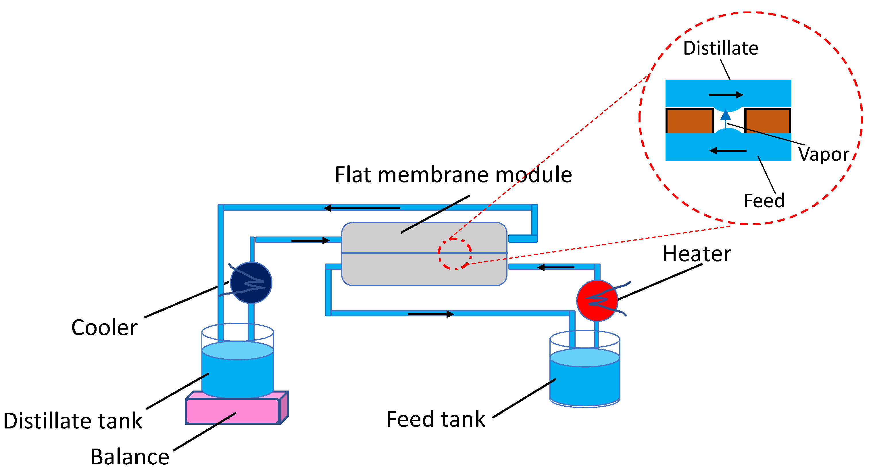
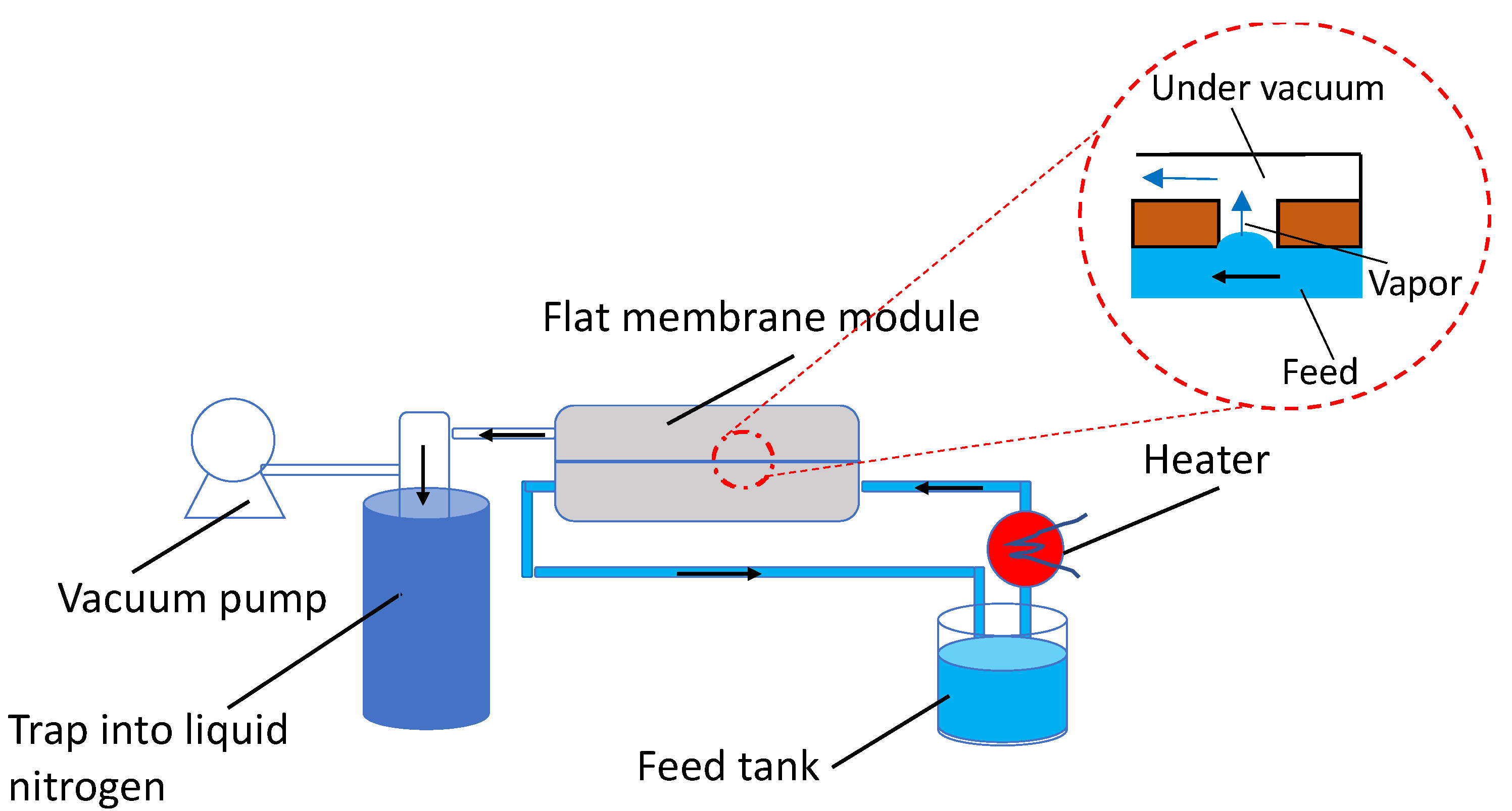
The DCMD and VMD tests were carried out on the same lab module (40 cm2 membrane area) where a flat commercial polypropylene membrane (0.2 μm pore size, 70% porosity, 91 μm thickness) purchased from Membrana (Germany), now 3M, was used. All tests were carried out on deionised water as feed, to make a more general analysis, then, avoiding any potential issues linked to a specific feed to be treated. Deionised water was sent to the bottom plate of the module in both cases and the feed-side was operated under the same conditions of flow rate and temperature. In particular, the flowrate was set at the highest value reachable by the pump (230 L/h, corresponding to a velocity of 0.46 m/s inside the module), in order to reduce the heat transfer resistance of the boundary layer, to promote more mixing, so as reducing fouling issues in applications with real aqueous streams, and to decrease the feed temperature decay along the module, by reducing its residence time. The feed temperatures at the inlet and outlet of the module were read by thermocouples. At the top plate, a cold deionised stream was sent in counter-current during DCMD experiments and the permeated vapor was directly condensed at the membrane-cold interface, while a vacuum was applied for VMD runs. In the latter configuration, the top plate had only one exit active for the permeate removal and its condensation occurred in a trap immersed into liquid nitrogen. Liquid nitrogen was used to ensure that all water vapor was condensed before the vacuum pump. It has to be noticed that this step can also be made using cooling fluids in specifically designed condensers. Figure 1 and Figure 2 show the schemes of the DCMD and VMD lab set-ups, respectively.
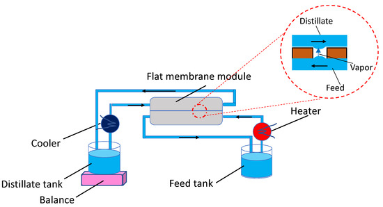
Figure 1.
Scheme of the DCMD lab set-up and sketch of the vapor transport through a micropore.

Figure 2.
Scheme of the VMD lab set-up and sketch of the vapor transport through a micropore.
In order to operate at a similar driving force during the VMD and DCMD experiments, a vacuum of 20 mbar was applied at the permeate side in VMD, while in DCMD the cold stream was recirculated at 18 °C temperature, at which the water vapor pressure is 19.7 mbar. The main operating conditions used are summarized in Table 2.
Table 2.
Main operating conditions used during DCMD and VMD tests.
2.2. Followed Methodology
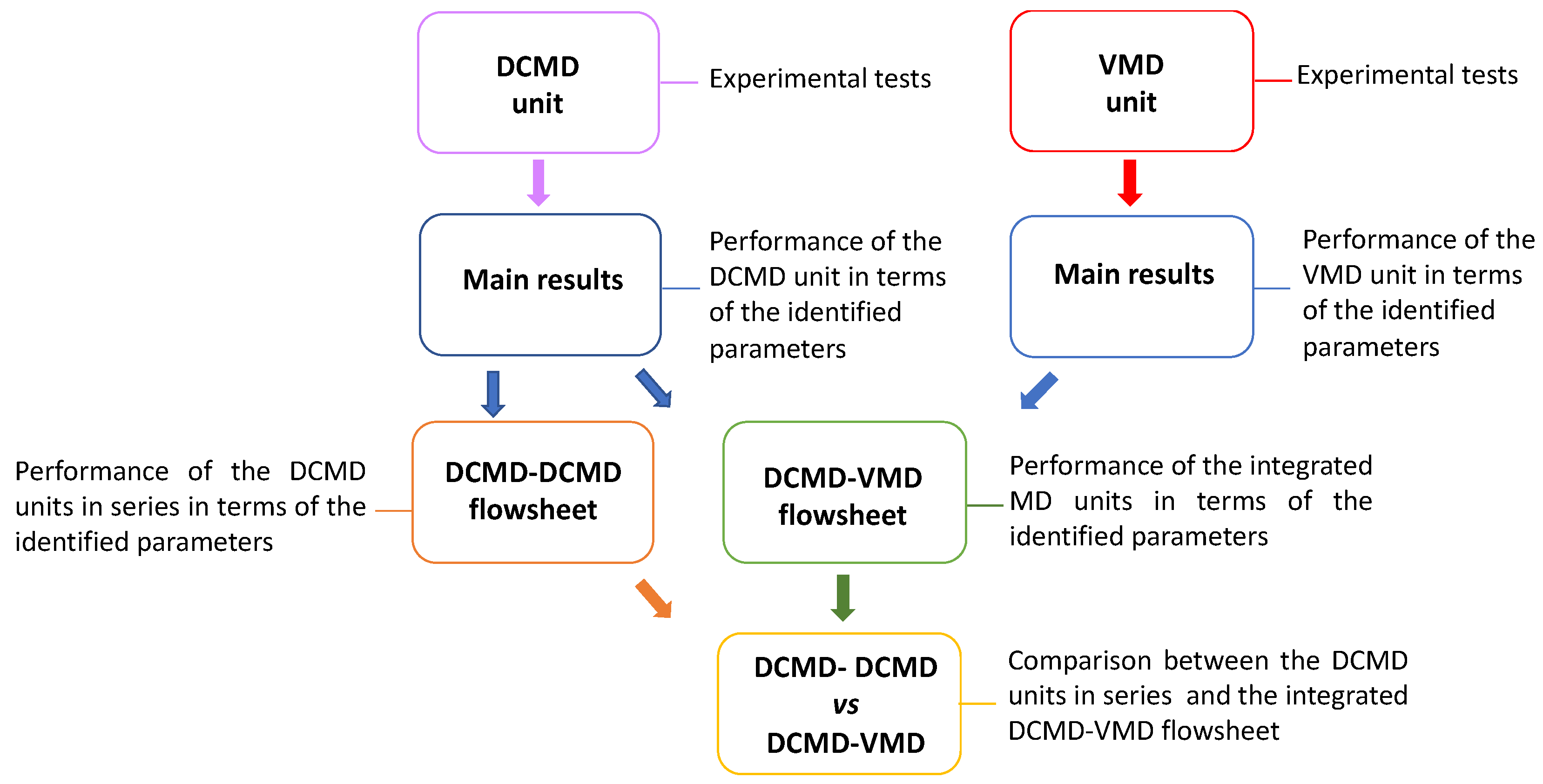
Based on the tests carried out on the single DCMD and VMD units, the related trans-membrane flux and decay of feed temperature along the module for the two MD configurations were obtained. Then, the experimental values were used to analyse each unit in terms of permeate production, thermal energy consumption and efficiency of evaporation (see the following sections for details on their calculation). The same analysis was then extended to the DCMD–DCMD and integrated DCMD–VMD flowsheets, which were proposed considering the experimental results. Finally, the integrated DCMD–VMD flowsheet was compared, also in terms of size, with the two DCMD units in series. Figure 3 summarizes the followed steps.
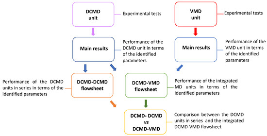
Figure 3.
Summary of the steps followed in this work.
2.3. Flux and Permeate Flow Rate Calculation
In DCMD, the mass of the permeate was weighed by a balance located under the distillate tank. In VMD, the permeate was first recovered as liquid into the trap and afterwards weighed. In both cases, the flux (J) was calculated by dividing the permeate mass (m, g) by the membrane area (Am, m2) and the experimental time (t, h):
The permeate flow rate (Qp, g/h) was obtained by multiplying the permeate flux by the membrane area:
2.4. Specific Thermal Energy Consumption and Gained Output Ratio Calculation
The STEC represents the thermal energy consumption (QH) associated with a certain permeate production and it is given by the ratio between the total thermal energy consumption (J/h) and the permeate flow rate:
The GOR gives an indication of how much of the thermal energy consumption (QH) is used to produce the permeate (evaporation efficiency), and it can be calculated by the ratio between the thermal energy effectively used for the evaporation and the total thermal energy consumption:
In the above formula, ΔHv is the enthalpy of vaporization (J/g).
QH is given by the sum of the single thermal energies (QHi) supplied to the plant:
Each thermal energy is calculated as function of the properties of the stream i, such as its flow rate Qfi (g/h), its specific heat capacity cpi (J/gK) and its difference of temperature in the plant ΔTi (K):
2.5. Productivity/Size Ratio Calculation
The PS ratio is a metric introduced to compare plants in terms of the process intensification strategy parameters. In this strategy, an important aspect of future plants is to work with higher productivity and reduced size [36]. In this respect, the PS ratio aims to compare the ratio of the productivity and size of two plants [37] and in this study was used to compare the investigated membrane distillation flowsheets by means of the following formula:
If PS is higher than 1, the MD flowsheet where the different MD units are integrated (DCMD–VMD) must be preferred.
3. Results and Discussion
3.1. Single DCMD and VMD Units
Figure 4 shows the trans-membrane fluxes measured and the variations of the feed temperature (ΔTf = Tfin − Tfout) registered for the two MD units. The experiments were repeated to ensure the reproducibility of the results and the average flux values are reported. A significant difference in flux was observed, even though the same driving force was applied. Being that the fluid dynamic at the feed-side is the same for the two MD configurations, the difference in flux can be attributed to an increase in the vapor pressure at the membrane-cold side of the DCMD unit. In fact, the distillate temperature at the membrane surface can be higher than that of the bulk, due to temperature polarization phenomena, which did not allow a fast removal of both the condensation heat and the heat transferred by conduction through the membrane polymer from the feed to the distillate side [28]. Moreover, due to the negligible conductive heat loss in VMD, a higher driving force is established during the VMD tests [34]. Finally, the vapor transport through the micropores is usually regulated by a combination of the Knudsen and molecular diffusion mechanisms in DCMD, whilst the Knudsen mechanism dominates in VMD [38]. Concerning the decay of the feed temperature along the module, a slightly higher value was registered for the DCMD tests, probably because of the heat lost by conduction through the polymer.
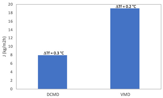
Figure 4.
Trans-membrane flux and feed temperature variation for the two MD units.
The obtained results are in agreement with the literature data reported in Table 1, confirming the higher productivity of the VMD configuration at parity of feed-side conditions.
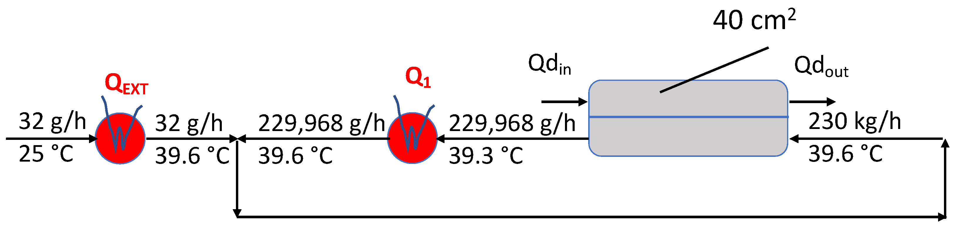
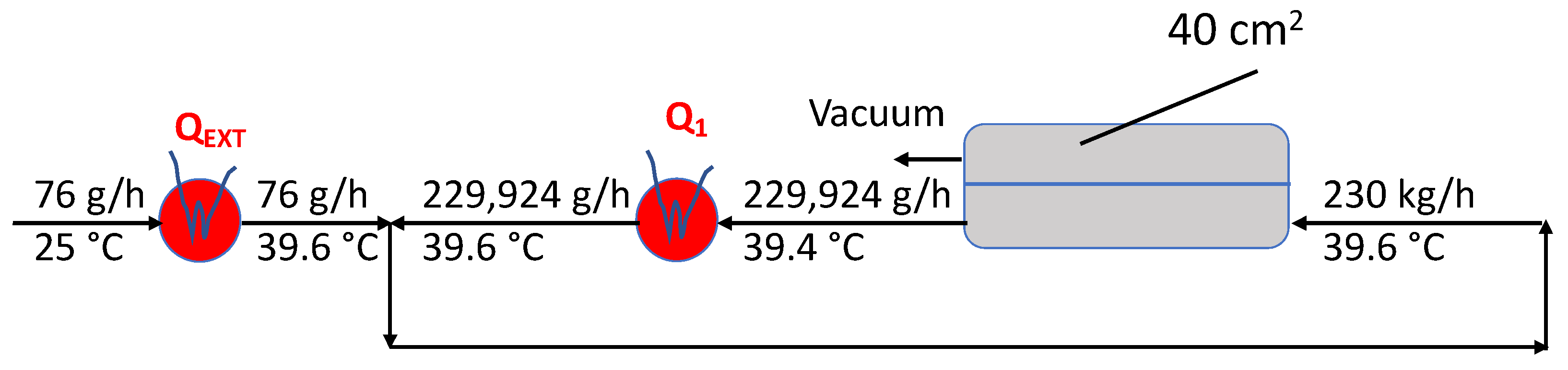
Based on the operating conditions and the obtained data, the flowsheets for the two MD configurations were sketched, as reported in Figure 5 and Figure 6. In particular, each flowsheet includes the flow rates and the temperatures of the feed streams, together with the thermal supplies needed. From them, the main parameters for comparing the DCMD and the VMD performance were calculated by Equations (2)–(4), and they are listed in Table 3. It is evident that the VMD unit was more efficient, leading to a higher permeate production and GOR and to a lower STEC. The main reason for these positive results lies in the much higher permeate flux achievable with the VMD configuration.

Figure 5.
DCMD flowsheet.

Figure 6.
VMD flowsheet.
Table 3.
DCMD and VMD performances.
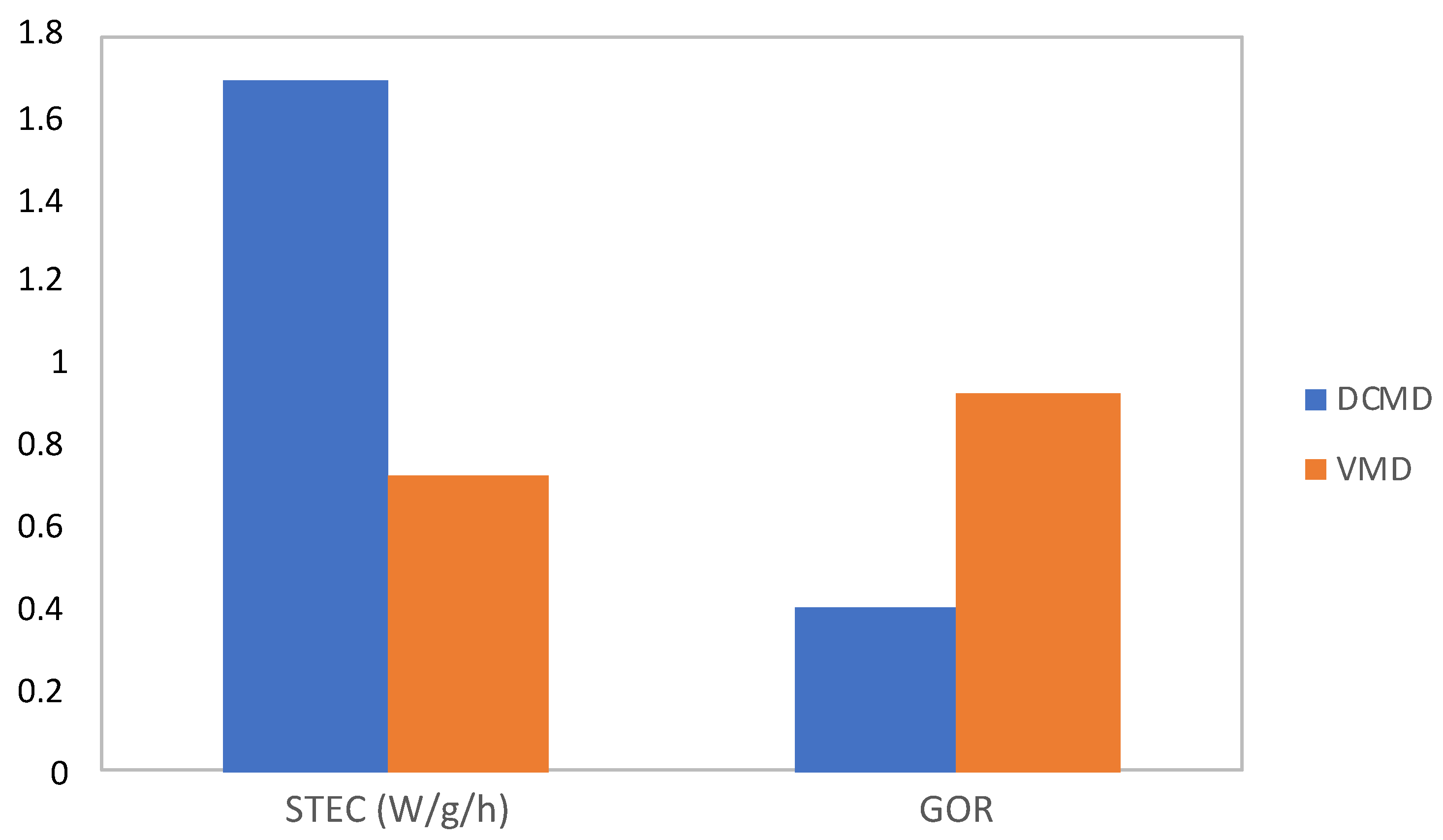
In fact, by comparing the STEC and GOR of the two membrane operations at parity of feed temperature decay along the module, the VMD unit always led to a better performance, as reported in Figure 7 and Figure 8, thanks to the more than double permeate production with respect to the DCMD configuration. In particular, when the same temperature decay registered in the VMD tests was considered (0.2 °C), the STEC of the DCMD unit decreased from 2.52 W/g/h to 1.69 W/g/h, while the GOR increased from 0.27 to 0.4. When the feed temperature decay measured in the DCMD tests was applied (0.3 °C), the STEC and the GOR of the VMD unit moved from 0.72 W/g/h to 1.07 W/g/h and from 0.93 to 0.62, respectively.
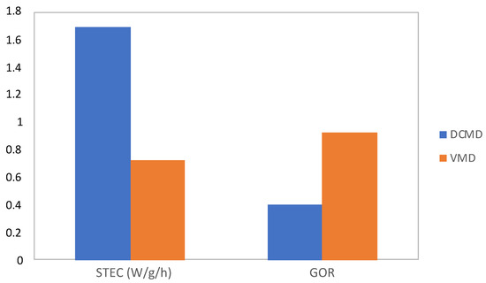
Figure 7.
STEC and GOR of the two MD units, considering for both the experimental feed temperature decay of the VMD unit (0.2 °C).

Figure 8.
STEC and GOR of the two MD units, considering for both the experimental feed temperature decay of the DCMD unit (0.3 °C).
3.2. DCMD Units in Series
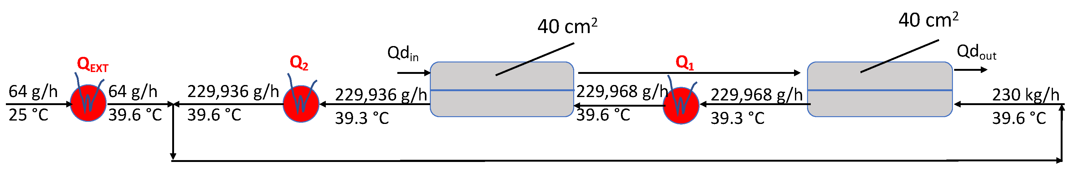
Based on the experimental results on the DCMD unit, a flowsheet where two DCMD units work in series was analysed, as reported in Figure 9. Both DCMD units worked in the same manner as the experimental one, since the stream exiting the first DCMD unit was heated up to the experimental temperature (39.6 °C) before entering the second DCMD unit. The calculated STEC and GOR of the flowsheet were the same as those of the single DCMD unit, the only difference being the higher membrane area (80 cm2) and permeate production (64 g/h).

Figure 9.
DCMD–DCMD flowsheet.
3.3. Integrated DCMD–VMD Units
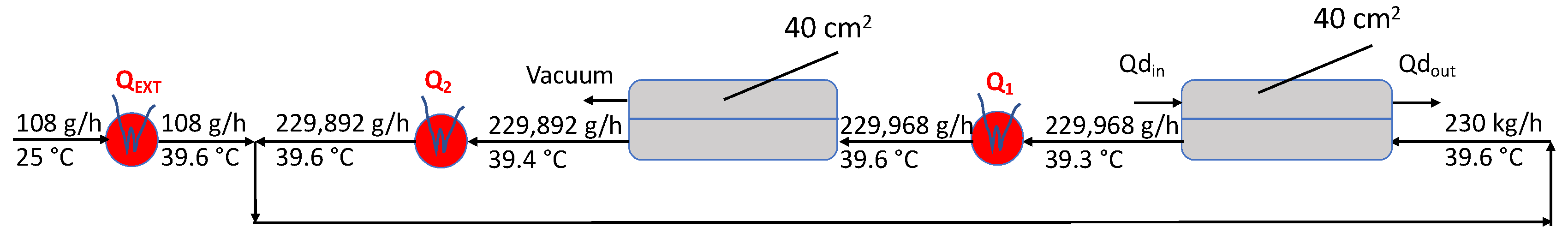
After having analysed the single MD units, an integrated DCMD–VMD flowsheet was investigated, with the aim of boosting the DCMD thermal performance, taking advantage of the higher efficiency of VMD. In this case, the feed stream exiting the DCMD unit was sent to the VMD one before being recycled back to the DCMD module (see Figure 10). As for the DCMD units in series, in the integrated configuration, both DCMD and VMD units operated under the same experimental conditions used in the single DCMD and VMD flowsheets, respectively.
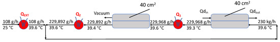
Figure 10.
Integrated DCMD–VMD flowsheet.
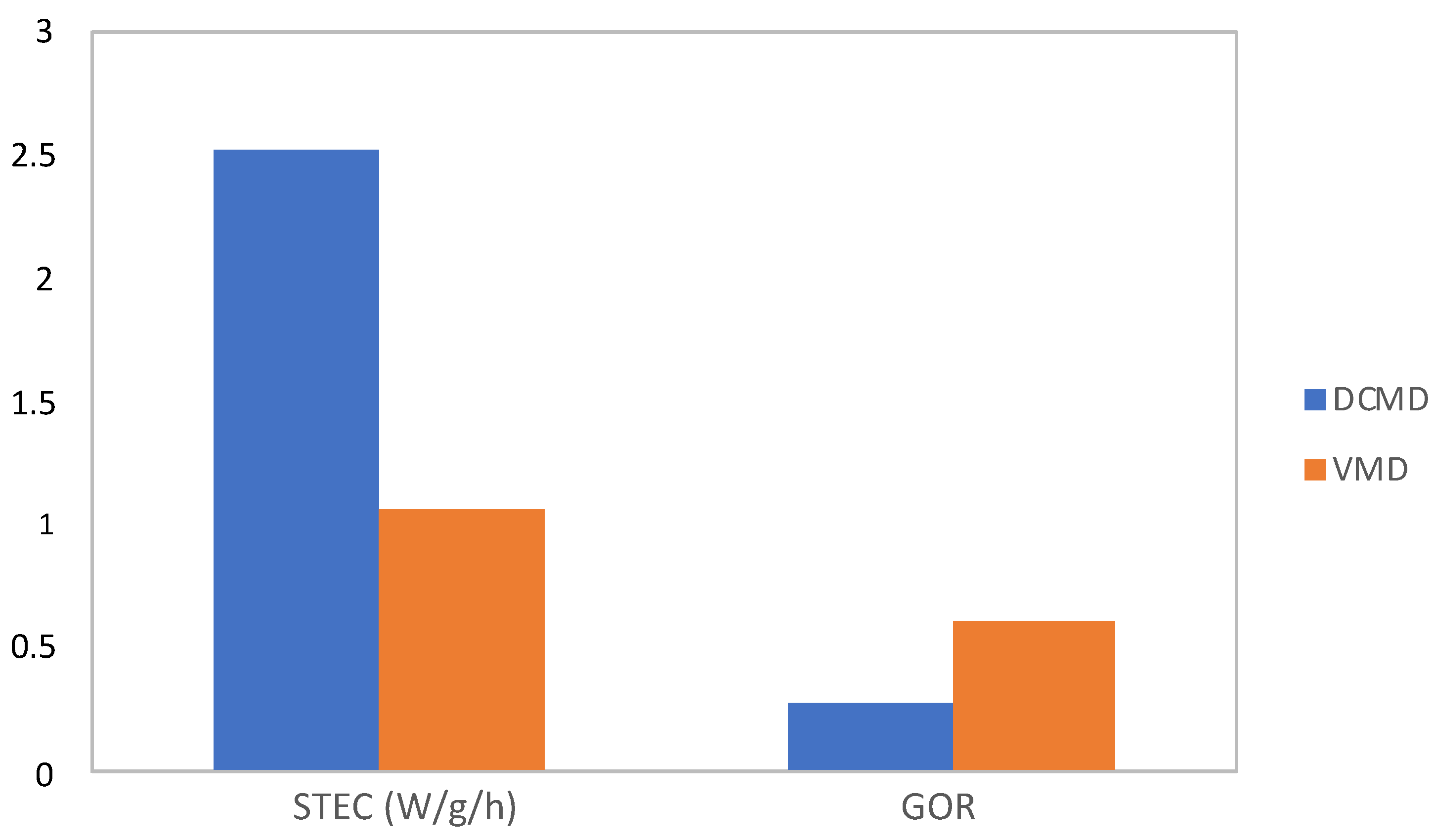
Table 4 compares the flowsheet with the DCMD units in series to the DCMD–VMD one in terms of permeate production. At parity of the membrane area, the integrated flowsheet led to a substantial increment of productivity, moving from 64 g/L to 108 g/L. It also showed lower STEC and higher GOR values (see Figure 11), thus improving the thermal performance of the DCMD unit.
Table 4.
Comparison between the flowsheet with the DCMD units in series and the integrated DCMD–VMD flowsheet in terms of permeate production.
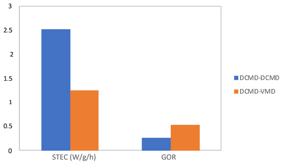
Figure 11.
Comparison between the flowsheet with the DCMD units in series and the integrated DCMD–VMD flowsheet in terms of STEC and GOR.
Specifically, gains obtained with the integrated DCMD–VMD flowsheet are summarized in Table 5. It is clear that, despite the same membrane area, the Productivity/Size ratio is in favour of the new proposed integrated MD configuration, thanks to the significant increase in the permeate production.
Table 5.
Gain obtained with the integrated DCMD–VMD flowsheet.
4. Conclusions
For the first time, as an alternative strategy to improve the thermal performance and the water recovery factor of DCMD, the integration of DCMD and VMD was proposed and investigated. In particular, the analysis was carried out at low operating temperatures (40 °C), for which the existing heat recovery methods are not very efficient, since they usually work at temperatures higher than 50 °C. Calculations were also made for a flow sheet consisting of two DCMD units in series, representing the “traditional” way in which more units of the same MD configuration are combined to enhance the water recovery factor.
The integrated DCMD–VMD flowsheet led to significant benefits with respect to the DCMD–DCMD units:
- (i)
- Reduction of the STEC (by 50%);
- (ii)
- Increase in the GOR (by 100%);
- (iii)
- Increase in the permeate production (by 69%);
- (iv)
- Higher productivity per membrane area (PS = 1.69).
On the basis of the above considerations, the application of a VMD unit in series with the DCMD one resulted to be an interesting way to improve both thermal performance and plant productivity, while fitting well the requirements of the process intensification strategy. It has to be pointed out that, although this work was carried out to cover the application of DCMD for treating feeds that need low operating temperatures, the same concept can be extended to higher operating temperatures and, then, to a wider number of processes. In this case, a comparison of the thermal performance of the proposed integrated MD flowsheet with that of existing heat recovery methods must be made, in order to identify the most effective one.
Funding
This research received no external funding.
Conflicts of Interest
The author declares no conflict of interest.
References
- Chiam, C.-K.; Sarbatly, R. Vacuum membrane distillation processes for aqueous solution treatment—A review. Chem. Eng. Process. Process. Intensif. 2013, 74, 27–54. [Google Scholar] [CrossRef]
- Abu-Zeid, M.A.E.-R.; Zhang, Y.; Dong, H.; Zhang, L.; Chen, H.-L.; Hou, L. A comprehensive review of vacuum membrane distillation technique. Desalination 2015, 356, 1–14. [Google Scholar] [CrossRef]
- Wang, P.; Chung, T.-S. Recent advances in membrane distillation processes: Membrane development, configuration design and application exploring. J. Membr. Sci. 2015, 474, 39–56. [Google Scholar] [CrossRef]
- Ashoor, B.B.; Mansour, S.; Giwa, A.; Dufour, V.; Hasan, S.W. Principles and applications of direct contact membrane distillation (DCMD): A comprehensive review. Desalination 2016, 398, 222–246. [Google Scholar] [CrossRef]
- Tavakkoli, S.; Lokare, O.; Vidic, R.; Khanna, V. A techno-economic assessment of membrane distillation for treatment of Marcellus shale produced water. Desalination 2017, 416, 24–34. [Google Scholar] [CrossRef]
- Chen, Y.R.; Chen, L.H.; Chen, C.H.; Ko, C.C.; Huang, A.; Li, C.L.; Chuang, C.J.; Tung, K.L. Hydrophobic alumina hollow fiber membranes for sucrose concentration by vacuum membrane distillation. J. Membr. Sci. 2018, 555, 250–257. [Google Scholar] [CrossRef]
- Khumalo, N.; Nthunya, L.; Derese, S.; Motsa, M.; Verliefde, A.; Kuvarega, A.; Mamba, B.B.; Mhlanga, S.; Dlamini, D.S. Water recovery from hydrolysed human urine samples via direct contact membrane distillation using PVDF/PTFE membrane. Sep. Purif. Technol. 2019, 211, 610–617. [Google Scholar] [CrossRef]
- Criscuoli, A. Improvement of the membrane distillation performance through the integration of different configurations. Chem. Eng. Res. Des. 2016, 111, 316–322. [Google Scholar] [CrossRef]
- Deshmukh, A.; Boo, C.; Karanikola, V.; Lin, S.; Straub, A.P.; Tong, T.; Warsinger, D.M.; Elimelech, M. Membrane distillation at the water-energy nexus: Limits, opportunities, and challenges. Energy Environ. Sci. 2018, 11, 1177–1196. [Google Scholar] [CrossRef]
- Lokare, O.R.; Tavakkoli, S.; Khanna, V.; Vidic, R.D. Importance of feed recirculation for the overall energy consumption in membrane distillation systems. Desalination 2018, 428, 250–254. [Google Scholar] [CrossRef]
- Raluy, G.R.; Schwantes, R.; Subiela, V.J.; Penate, B.; Melian, G.; Betancort, J. Operational experience of a solar membrane distillation demonstration plant in Pozo Izquierdo-Gran Canaria Island (Spain). Desalination 2012, 290, 1–13. [Google Scholar] [CrossRef]
- Saffarini, R.B.; Summers, E.K.; Arafat, H.A.; Leinhard, J.H.V. Technical evaluation of stand-alone solar powered membrane distillation systems. Desalination 2012, 286, 332–341. [Google Scholar] [CrossRef]
- Suárez, F.; Ruskowitz, J.A.; Tyler, S.W.; Childress, A.E. Renewable water: Direct contact membrane distillation coupled with solar ponds. Appl. Energy 2015, 158, 532–539. [Google Scholar] [CrossRef] [Green Version]
- Winter, D.; Koschikowski, J.; Wieghaus, M. Desalination using membrane distillation: Experimental studies on full scale spiral wound modules. J. Membr. Sci. 2011, 375, 104–112. [Google Scholar] [CrossRef]
- Zhao, K.; Heinzl, W.; Wenzel, M.; Buttner, S.; Bollen, F.; Lange, G.; Heinzl, S.; Sarda, N. Experimental study of the memsys vacuum-multi-effect-membrane-distillation (V-MEMD) module. Desalination 2013, 323, 150–160. [Google Scholar] [CrossRef]
- Jansen, A.E.; Assink, J.W.; Hanemaaijer, J.H.; van Medevoort, J.; van Sonsbeek, E. Development and pilot testing of full-scale membrane distillation modules for deployment of waste heat. Desalination 2013, 323, 55–65. [Google Scholar] [CrossRef]
- Wu, X.; Jiang, Q.; Ghim, D.; Singamaneni, S.; Jun, Y.-S. Localized heating with a photothermal polydopamine coating facilitates a novel membrane distillation process. J. Mater. Chem. A 2018, 6, 18799–18807. [Google Scholar] [CrossRef]
- Huang, Q.; Gao, S.; Huang, Y.; Zhang, M.; Xiao, C. Study on photothermal PVDF/ATO nanofiber membrane and its membrane distillation performance. J. Membr. Sci. 2019, 582, 203–210. [Google Scholar] [CrossRef]
- Alsaati, A.; Marconnet, A.M. Energy efficient membrane distillation through localized heating. Desalination 2018, 442, 99–107. [Google Scholar] [CrossRef]
- Tan, Y.Z.; Han, L.; Chew, N.G.P.; Chow, W.H.; Wang, R.; Chew, J.W. Membrane distillation hybridized with a thermoelectric heat pump for energy-efficient water treatment and space cooling. Appl. Energy 2018, 231, 1079–1088. [Google Scholar] [CrossRef]
- Ahmed, F.E.; Lalia, B.S.; Hashaikeh, R.; Hilal, N. Enhanced performance of direct contact membrane distillation via selected electrothermal heating of membrane surface. J. Membr. Sci. 2020, 610, 118224. [Google Scholar] [CrossRef]
- Lee, H.Y.; He, F.; Song, L.M.; Gilron, J.; Sirkar, K.K. Desalination with a cascade of cross-flow hollow fiber membrane distillation devices integrated with a heat exchanger. AICHE J. 2011, 57, 1780–1795. [Google Scholar] [CrossRef]
- Lin, S.; Yip, N.Y.; Elimelech, M. Direct contact membrane distillation with heat recovery: Thermodynamic insights from module scale modeling. J. Membr. Sci. 2014, 453, 498–515. [Google Scholar] [CrossRef]
- Guan, G.; Yang, X.; Wang, R.; Fane, A.G. Evaluation of heat utilization in membrane distillation desalination system integrated with heat recovery. Desalination 2015, 366, 80–93. [Google Scholar] [CrossRef]
- Swaminathan, J.; Lienhard, J.H.V. Design and operation of membrane distillation with feed recirculation for high recovery brine concentration. Desalination 2018, 445, 51–62. [Google Scholar] [CrossRef] [Green Version]
- Tang, Y.; Li, N.; Liu, A.; Ding, S.; Yi, C.; Liu, H. Effect of spinning conditions on the structure and performance of hydrophobic PVDF hollow fiber membranes for membrane distillation. Desalination 2012, 287, 326–339. [Google Scholar] [CrossRef]
- Fan, H.; Peng, Y. Application of PVDF membranes in desalination and comparison of the VMD and DCMD processes. Chem. Eng. Sci. 2012, 79, 94–102. [Google Scholar] [CrossRef]
- Drioli, E.; Ali, A.; Simone, S.; Macedonio, F.; AL-Jlil, S.A.; Al Shabonah, F.S.; Al-Romaih, H.S.; Al-Harbi, O.; Figoli, A.; Criscuoli, A. Novel PVDF hollow fiber membranes for vacuum and direct contact membrane distillation applications. Sep. Pur. Technol. 2013, 115, 27–38. [Google Scholar] [CrossRef]
- Zhang, J.W.; Fang, H.; Wang, J.W.; Hao, L.Y.; Xu, X.; Chen, C.S. Preparation and characterization of silicon nitride hollow fiber membranes for seawater desalination. J. Membr. Sci. 2014, 450, 197–206. [Google Scholar] [CrossRef]
- Carnevale, M.C.; Gnisci, E.; Hilal, J.; Criscuoli, A. Direct Contact and Vacuum Membrane Distillation application for the olive mill wastewater treatment. Sep. Purif. Technol. 2016, 169, 121–127. [Google Scholar] [CrossRef]
- Ramlow, H.; Machado, R.A.F.; Bierhalz, A.C.K.; Marangoni, C. Influence of dye class on the comparison of direct contact and vacuum membrane distillation applied to remediation of dyeing wastewater. J. Environ. Sci. Heal. Part A 2019, 54, 1337–1347. [Google Scholar] [CrossRef] [PubMed]
- Schnittger, J.; McCutcheon, J.; Hoyer, T.; Weyd, M.; Fischer, G.; Puhlfürß, P.; Halisch, M.; Voigt, I.; Lerch, A. Hydrophobic ceramic membranes in MD processes—Impact of material selection and layer characteristics. J. Membr. Sci. 2021, 618, 118678. [Google Scholar] [CrossRef]
- Sparenberg, M.-C.; Hanot, B.; Molina-Fernández, C.; Luis, P. Experimental mass transfer comparison between vacuum and direct contact membrane distillation for the concentration of carbonate solutions. Sep. Pur. Technol. 2021, 275, 119193. [Google Scholar] [CrossRef]
- Guan, G.; Yang, X.; Wang, R.; Field, R.; Fane, A.G. Evaluation of hollow fiber-based direct contact and vacuum membrane distillation systems using aspen process simulation. J. Membr. Sci. 2014, 464, 127–139. [Google Scholar] [CrossRef]
- Mericq, J.-P.; Laborie, S.; Cabassud, C. Evaluation of systems coupling vacuum membrane distillation and solar energy for seawater desalination. Chem. Eng. J. 2011, 166, 596–606. [Google Scholar] [CrossRef]
- Stankiewicz, A.; Moulijn, J.A. Process intensification: Transforming chemical engineering. Chem. Eng. Prog. 2000, 96, 22–23. [Google Scholar]
- Criscuoli, A.; Drioli, E. New metrics for evaluating the performance of membrane operations in the logic of process intensification. Ind. Eng. Chem. Res. 2007, 46, 2268–2271. [Google Scholar] [CrossRef]
- Mengual, J.I.; Khayet, M.; Godino, M.P. Heat and mass transfer in vacuum membrane distillation. Int. J. Heat Mass Transf. 2004, 47, 865–875. [Google Scholar] [CrossRef]


Publisher’s Note: MDPI stays neutral with regard to jurisdictional claims in published maps and institutional affiliations. |
© 2021 by the author. Licensee MDPI, Basel, Switzerland. This article is an open access article distributed under the terms and conditions of the Creative Commons Attribution (CC BY) license (https://creativecommons.org/licenses/by/4.0/).