1. Introduction
Reliability analysis is the technical framework to study system breakdown and quantification of its probability [
1]. Reliability describes the capability of the system or component to function in different conditions for a specified time. Safe and reliable engineering systems, such as aircraft engines, is significantly important for modern power plants, production quality, health protection, human life, etc. [
2]. Indeed, reliability is theoretically defined by breakdown probability, breakdown frequency, or, in terms of availability, the probability arising out of reliability and ease of maintenance. Reliability plays a crucial role in system cost-effectiveness [
3,
4]. Measures of reliability are analyzed taking into consideration the reliability function, expected durability, coefficient of breakdown and risk function, reliability and risk function for the known distributions, risk models and product lifetime, assessing risk and reliability functions based on empirical data and remarks regarding the selection of distribution. The statistical reliability models are considered along with probabilistic aspects of engineering design, the combination of random variables in the design, interference theory and reliability calculations, examples of designing reliability, reliability models depending on time, dynamic reliability models, exponential distribution, Weibull distribution, sequential durability testing, and issues of reliability optimization.
During aircraft operation, assemblies and aggregates are subjected to permanent diagnostic inspections, and their technical condition is expressed by a set of diagnostic parameters. The knowledge of the current values of the acceptable parameters and limit states enables us to assess the current technical condition of the given object. Data from the operational process can enable to forecast the technical condition by constructing mathematical models based on which the failure-free operating period of the assembly or aggregate can be estimated.
The research method presented in this publication consists of estimating the reliability of the starter-generator based on the flight profile and diagnostic data obtained from the operation process. The method has been developed at the Air Force Institute of Technology. The novelty of this method is the estimation of bearing life based on the criterion of only one parameter, which is the flight altitude. Converting the flight altitude to temperature by means of a reference atmosphere, we obtain the temperature profile. Based on this profile and on numerical calculations, we can determine the reliability and durability of bearings in airborne commutator machines. Since bearings in airborne commutator machines are almost impossible to examine technically, the temperature profile is one of the most readily available pieces of information on the aircraft flight path and, consequently, on bearing wear. The developed method makes it possible to predict changes in the values of diagnostic parameters and operating time while ensuring the appropriate level of reliability.
2. Literature Review
Prognostics is the continuation of diagnostics. Diagnostics consists of identifying error, which will lead to malfunction and estimation of its significance, and prognostics is based on constant monitoring of variables and system parameters and using this information to assess time to failure, named as remaining useful life (RUL) [
5,
6,
7]. Alternatively, in other words, prognostics aims to forecast the development of failure and predict when the machine will no longer operate according to assumptions or requirements [
8]. The prognostics can be used to evaluate the degradation rate and can allow the regular operation of the machine until failure appears, can reduce unnecessary, cost-effective inspections, and unpredictable breakdowns [
9]. The current methods of predicting damages in rotary machines are summed up and classified as conventional reliability models, prognostic models based on state, and models combining reliability and prognostics. The areas requiring preparation and development include the integration of monitoring state and reliability, usage of incomplete data on trends, including the maintenance works and changeable operating conditions, deriving a non-linear relation between parameter data and real technical state, taking into account the interaction between failures, the practicability of requirements and assumptions, as well as the preparation of a framework of efficiency assessment [
10].
In the literature on predicting the service life of commutator machines [
11], the prediction method of the remaining service life of bearings based on a non-linear model of the Wiener process was described. Firstly, the service life of bearings is divided into two stages in terms of the operating state. Then, the new prognostic model reflecting the relation between time and reliability state of the bearing is constructed. The subsequent authors [
12] developed a method that combines a general Weibull failure rate function (WFRF) and neural network with radial basis function (RBF). The classic approach is based on data that depend on manual separation of the features from raw data from sensors, and then the estimation of failure rate, degradation state, and RUL prediction is completed using the breakdown threshold [
13]. By applying the development of deep neural networks in different areas of artificial intelligence, they suggested a complex deep structure to estimate RUL based on recurrent units with conventional and long short term memory (LSTM) [
14,
15].
By analyzing methods used to investigate the remaining operating time, data-based methods should not be forgotten. In models based on direct data, models such as methods using [
16] regression models [
17], Wiener process [
18], Gamma processes, and Markov processes can be distinguished. For models depending on indirect data, models based on stochastic filtering, risk models based on covariance, hidden Markov models (HMM), and hidden semi-Markov models (HSMM) can be identified.
3. Importance of the Starter-Generator
The modern aircraft demand more and more electric energy [
19,
20]. Currently, there is a tendency to use DC generators as starter-generators. The starter-generator is an important part of the aircraft electrical system. The role of the starter-generator is to start the engine and generate electric energy during flight [
21]. Using the same machines as generators and engines follows, e.g., from economic concerns. Thanks to such a solution, the volume and mass of the starting system is increased. The disadvantage of such a solution is greater complexity of the control system of the starter-generator. The average starter-generator is slightly bigger (by approx. 10 ÷ 20%) in comparison with the generator of the same power. Apart from shunt excitation winding, starter-generators have also series winding. Thus, depending on the adopted starting system, they can operate as mixed excitation engines, mixed excitation series-shunt engines or series excitation engines. Series excitation winding is used only in the engine range. Thanks to this winding, the starting torque of the machine is higher, start-up time is shorter, and rotational speed at the end of the starting cycle is higher. The drive shaft of the starter-generator is connected with the shaft of the aircraft engine via a reducer with a variable gear ratio. Reliability of the starter-generator in the operational process is influenced by the operation of commutator-brush assembly. The unfavorable conditions of the commutator-brush assembly result in the deterioration of current and damage to the commutator and brushes [
22].
4. Maintenance Process of the Starter-Generator
The basic source of DC electric energy with a voltage of 28.5 V is a 200SGL129Q starter-generator with a control block of the GCSG 505 21 starter-generator. In the generator operation, a nickel-cadmium battery is connected in parallel to the starter-generator, which stabilizes the system operation under normal conditions, and in emergency conditions, is a source of direct current [
23,
24]. Moreover, in the generator operation, the starter-generator has a value that is sufficient to supply all receivers installed on the aircraft [
24].
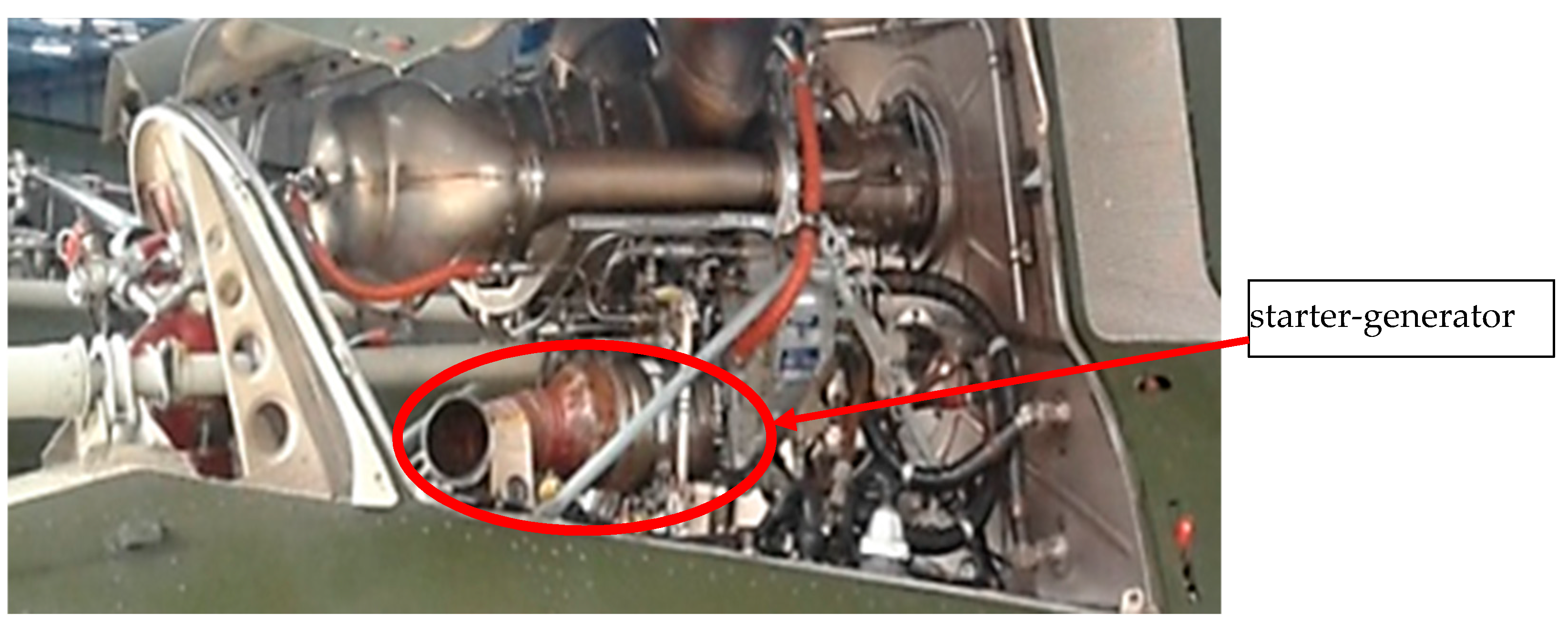
The starter-generator is installed on a Rolls-Royce 250-C20R/2(SP) engine from the right side, looking toward the flight direction (
Figure 1).
The starter-generator is applied for [
24]:
start-up of the Rolls-Royce 250-C20R/2(SP) engine (in the engine operation);
providing power to all current receivers installed on a helicopter, and boost charging of the on-board accumulator battery (in the generator operation) in the range of the engine’s idle run (59% N1 of the turbo compressor).
The starter-generator is a shunt DC machine equipped with a rotational speed sensor. It is attached to the engine drive box using a quick separable clamping ring. During start-up of the Rolls-Royce 250 C20R/2(SP) engine, power can be provided to the starter-generator from the on-board accumulator battery or ground power unit. The starter-generator is cooled with an integral ventilator. Inspections and maintenance of starter-generators are completed according to the Technical Manual Job Guide (in Polish JZOT OSPRZĘT) and compliant to the technical manual provided by the manufacturer of this starter-generator. As part of the D2 routine maintenance, the overhaul of the external condition of the starter-generator is completed [
25]. Inspecting the condition and calculating the wear of the current generator’s brushes is performed based on the operation sheet (in Polish. KT) No. 24.00-7. According to the operation sheet, brushes should be inspected after 500 operating hours of the starter-generator [
26]. Technical Manual Job Guide (JZOT OSPRZĘT) recommends inspecting the condition and calculating the service life of the starter-generator’s brushes during periodic maintenance 300 h/annual and 600 h/biennial, providing also the scope of the inspection according to the operation sheet No. 24.00-7 [
26,
27]. A graphical operational process of the starter-generator is illustrated in
Figure 2 [
23,
26].
5. Method for Determining Reliability of the Starter-Generator
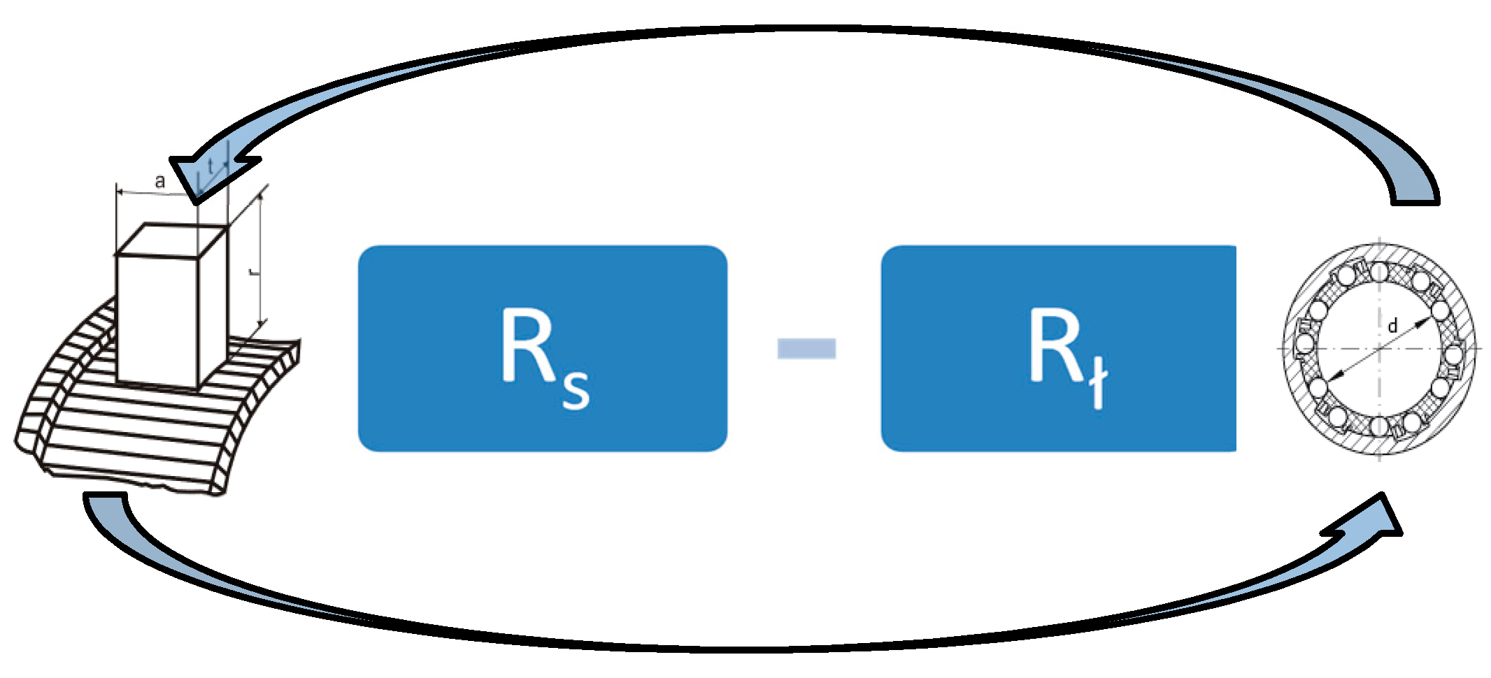
Based on the analysis of wear processes present in commutator machines, the reliability model as a reliability series structure was adopted in the calculations of the starter-generator. Constructing a reliability model of the starter-generator, it is necessary to treat it as a reliable series structure. Thus, it shows that failure of any of these elements results in failure of the whole system. Considering the reliable series structure for starter-generator it was adopted that it consists of two elements—brushes and bearings (
Figure 3).
To calculate a reliable series structure for the starter-generator, the following relation [
28] was applied:
where
—reliable series structure of the starter-generator;
—reliability of brushes of all starter-generators;
—reliability of bearings of the starter-generator.
To determine the reliability of the starter-generator, the methodology consisting of two stages was adopted. In the first stage, reliability and durability of brushes were defined based on density function of changes in the diagnostic parameter depending on the operating time. In the second stage, the reliability and durability of bearings in the starter-generator was estimated taking into account the flight profile of the helicopter.
6. Determining Density Function of Changes in Diagnostic Correlation Function Relative to the Operating Time
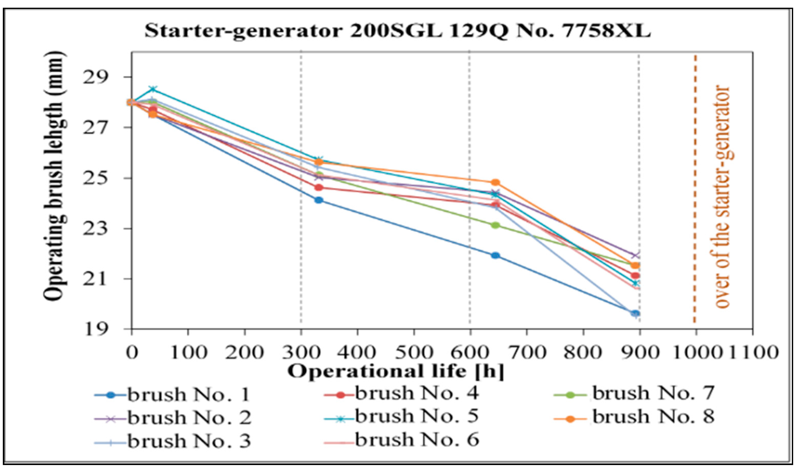
The research presented in the article was conducted for 10 200SGL129Q starter-generators. Each starter-generator consists of eight brushes. In the operational process of the starter-generator, maintenance works are performed during which the length of brushes is measured. When it is established that a given brush does not conform to requirements in terms of length, then such starter-generator is delivered to the general overhaul.
Figure 4 shows wear of the start-generator’s brushes No. 7758.
In the suggested method for the assessment of the durability of aircraft commutators, the following assumptions [
29,
30] were adopted:
- 2.
Due to the wear processes, the values of diagnostic parameters change. It is adopted that these changes have a monotonic character and can be described in the following form:
where
—absolute value of deviation of the diagnostic parameter from the nominal value;
—present value
i of this parameter;
—nominal value
i of this parameter;
- 3.
Aircraft commutator machine is serviceable if the following relation is met:
where
—absolute value of the limit deviation of diagnostic parameter from the nominal value;
For clarification, the following designations were introduced:
where
—absolute value of the deviation of diagnostic parameter from the nominal value;
—absolute value of the limit deviation of the diagnostic parameter from the nominal value;
- 4.
The increase of values of changes in diagnostic parameter is random;
- 5.
Changes in diagnostic parameters adopted for the assessment of the technical condition of aircraft commutators are independent random variables, i.e., the change in value of any of them does not affect the change in value of the others;
- 6.
The method is applicable to aircraft commutator machines, for which the speed of changes in the diagnostic parameter can be described by the following relation [
29,
31]:
where
—random variable characterizing changes depending on element features and work conditions;
—aircraft flight hours.
For the adopted assumptions, the dynamics of changes in diagnostic parameters was described by difference equation. The selected parameter is used in the analysis
. The adopted assumptions take the form of the following difference equation [
30,
32,
33,
34,
35]:
where
—probability that in instant
value of the diagnostic parameter will be
;
—probability that in the time interval of the length
, deviation value will increase by
;
—increment of the diagnostic parameter
during one flight of aircraft.
It follows from Equation (8) that it is probable that in the instant
value of deviation is
and in the time interval with length
increased by value
[
30,
36]. Thus, Equation (8) can be written in the following form [
11,
30,
36]:
Function (9) is a searched probabilistic characteristic of change in diagnostic parameter due to wear, the rate of which can be expressed by relationship (7). The density function of increasing the diagnostic parameter value can be used to estimate the reliability and durability of aircraft commutator machine, the technical condition of which is assessed by this parameter. The example of such a solution is the application of the density function of changes in diagnostic parameter to determine the time distribution of exceeding the limit state [
12].
7. Determining the Time Distribution of Exceeding the Limit State (Permissible)
The function described by Equation (9) has a probabilistic characteristic of change in diagnostic parameter. The change in the diagnostic parameter results from wear processes. The rate of these processes can be described by relation (7). The function presented above can be taken into consideration to estimate reliability and durability of the selected commutator machines, the technical condition of which can be described by this parameter. The example, where we can use the density function of changes in the value of diagnostic parameter is to determine the time distribution of exceeding the limit state. The probability of exceeding the limit value by a diagnostic parameter
can be depicted by means of a density function of changes in diagnostic parameter [
28,
34]:
To define the first-passage time density function beyond the permissible deviation
, the following relation needs to be used:
Then, by replacing Equation (10), we obtain the following dependence:
Further, we use differentiation and integration properties due to which the following relation is obtained:
Equation (13) defines the density function of exceeding the limit state by diagnostic parameter value [
30].
8. Reliability and Durability of the Selected Devices in Terms of Changes in a Diagnostic Parameter
The method for determining the time distribution of exceeding the limit state by a diagnostic parameter, described in point 3, allows to define the readiness function of the time of reaching a limit state. By knowing this function, it is possible to determine the reliability of the selected commutator machines, the technical condition of which is assessed based on the considered diagnostic parameter [
34,
37]:
where
The density function of the time distribution of the first passage of diagnostic parameter value through the limit state enables to calculate the durability of the selected commutator machines. By establishing the risk level of exceeding the limit state
the following relation (16) is obtained [
34]:
The value of time, for which the right side of relation (16) equals the left side, is determined by the durability of the selected commutators under conditions specified by the adopted assumptions.
9. Estimating Reliability and Durability Based on Starter-Generator Installed on the Aircraft
A diagnostic parameter, which is directly related to wear processes occurring during the operational process of the starter-generator, is the wear of brushes. Reliability and durability of the starter-generator are determined based on the density function of the time of passing a diagnostic parameter through the limit state by defining a and b estimators present in the equation [
38]:
The equation shown above is a solution for the starter-generator, the technical condition of which is characterized by one diagnostic parameter taking into consideration the standard parameter value to the range of [0,1] can be written in the following form [
39]:
where
—wear of starter-generator’s brushes in time
;
—wear of starter-generator’s brushes in time
.
Formula (18) takes the form of the density function of the probability of increment
s. To determine the distribution parameters of probability a and b, the method for plausibility function has to be used. In the general form, the function assumes the following shape [
39,
40]:
where
—density function of the total probability of variable
;
—parameters of the density function;
—measured values of parameter
in the moment of time, respectively
.
Taking subsequent diagnostic measurements of the tested machine during their operation, data were collected on increasing the deviation value of a diagnostic parameter in the following form:
Finding the estimates
of the unknown parameters
by the maximum likelihood method (MLM) comes down to solving equations in the form [
39]:
where
.
In this case, estimates
of the unknown parameters
and
by the maximum likelihood method comes down to the system of equations [
29]:
By solving the system of Equation (22), we find
:
10. Using the Density Function of the First-Passage Time of the Value of the Increasing Diagnostic Parameter through the Limit State to Estimate Reliability and Durability of the Starter-Generator
Calculations of the probabilistic indicators are completed in range of the permissible values in order to determine the starter-generator durability:
where
—boundary value of
i-th parameter, the exceedance of which results in the commutator machines being declared unserviceable;
—value of
i-th diagnostic parameter at the beginning of the operational process.
The formula for reliability of the starter-generator has the following form:
where density function
is written as:
The unreliability of the starter-generator is derived from [
39]:
By transforming dependence (28), the formula for reliability is obtained:
Taking into consideration the distribution function of the standard normal distribution
with the expected value which is 0 and variance, which is 1, the reliability of the starter-generator can be expressed as follows [
29]:
In order to usefully apply Equation (30) for calculations, the assumptions included in relation (31) on relative deviation of the diagnostic parameter value should be borne in mind:
Taking the above dependencies into account, the boundary value of parameter is 1, and formula for reliability assumes the following form [
39]:
Due to the fact that the density of the standard normal distribution is an even function, thus [
28,
39]:
where
Durability of the starter-generator due to parameter
is determined by solving Equation (16):
Using the following dependence:
Equation (16) will be expressed in the following form:
Assuming the reliability level
using standard normal distribution tables, one can define the value of relation:
thus
In this article, value
was used in calculations. When value
is determined, it is possible to define the value
from (38). Both sides of the equation should be squared, multiplied by
and then the following equation is obtained:
By making several transformations, the following relationship is achieved:
.
The above equation is a quadratic equation relative to time
. By solving the equation, the relationship for determining the searched durability is obtained [
8]:
11. Computing Reliability and Durability of the Starter-Generator Based on the Wear of Brushes
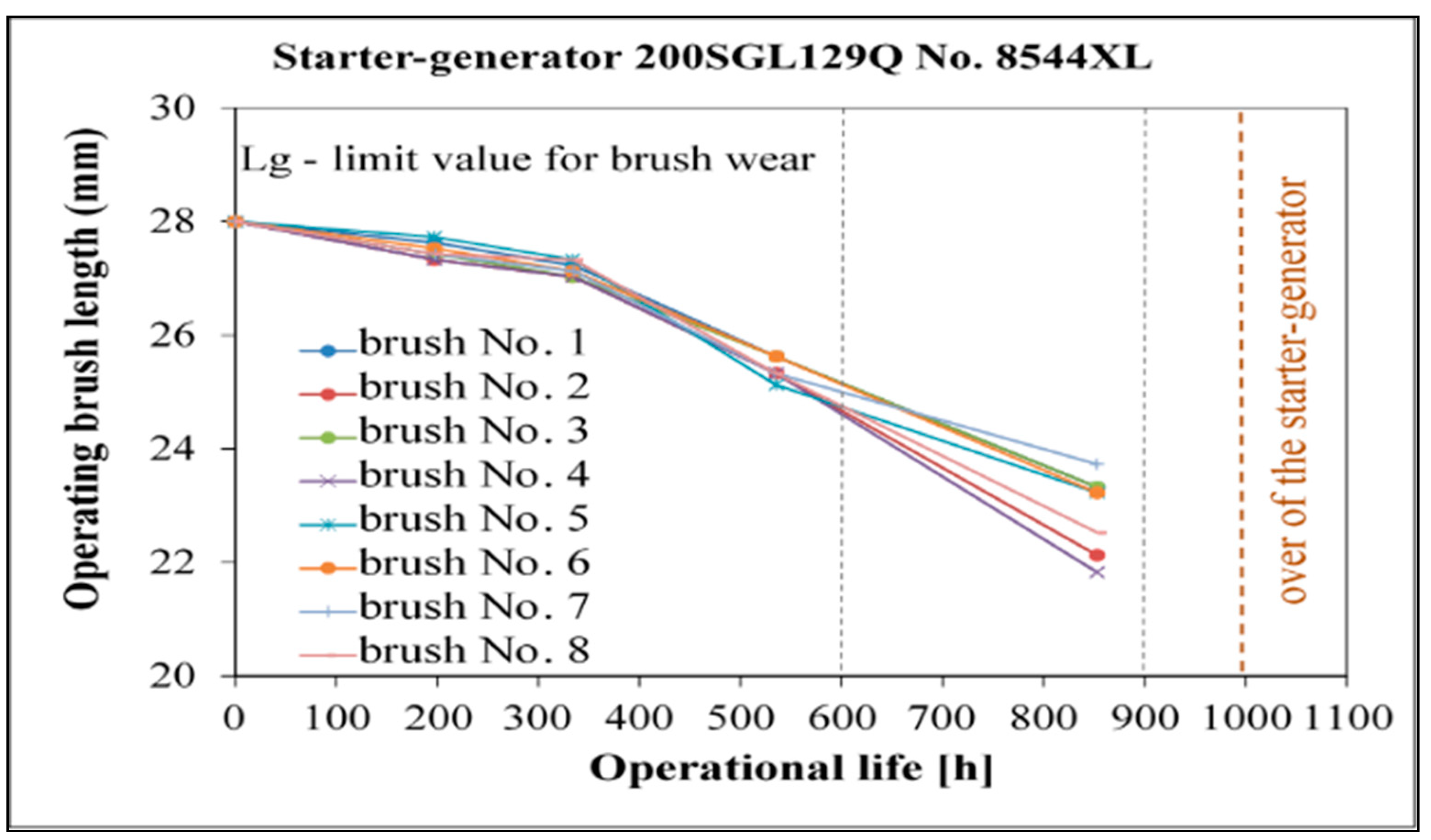
Brushes are the primary elements in the starter-generator. During operation, inspection of their technical condition is performed, and their durability is calculated. Building upon data from the operational process of brushes wear, the change in length of eight brushes of the starter-generator was determined in the function of the operating time (
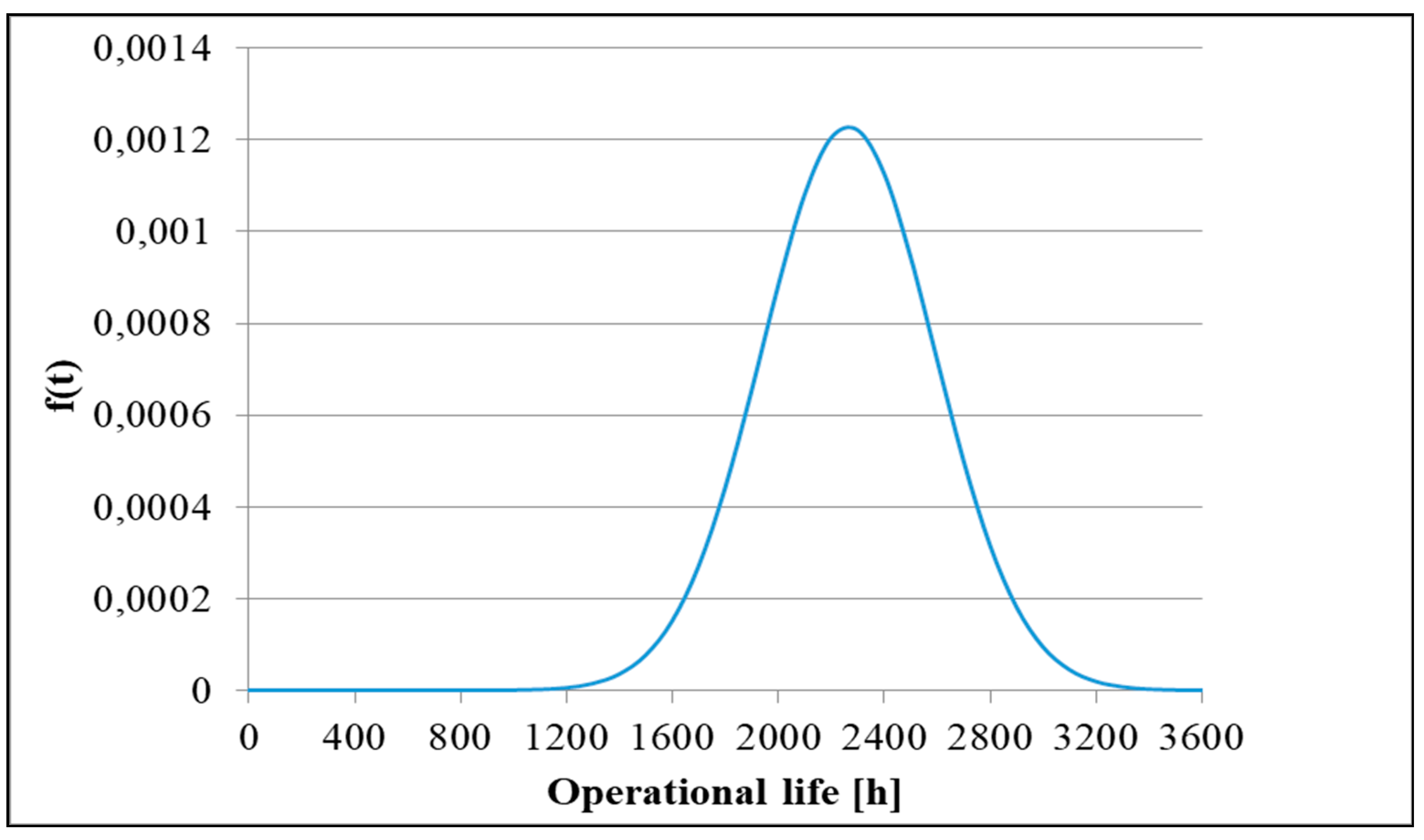
Figure 5). The graphical form of the density function of the rise time of deviation to the boundary value (
Figure 6), and the reliability function R(t) (
Figure 7), were also determined. The confidence level was assumed to be at R(t) = 0.90.
12. The Method for Estimating the Reliability of Starter-Generator’s Brushes Considering the Real User’s Profile
Durability of aircraft bearings in commutator machines was evaluated based on the method devised at the Air Force Institute of Technology. The method, which is applied to brush engines, assumed that the brushes were inspected or replaced by the new ones and were not damaged. It enables to define the durability of bearings in electric machines based on estimating the ambient temperature of the working aircraft commutator [
31].
To estimate the reliability of bearings in the starter-generator based on flight profile of SW-4 helicopter, calculations were used that describe the approximated approach to determine the average failure rate (the average number of failures within a given time of operation of a given machine). The average failure rate can be calculated based on the following relationship [
41,
42]:
where
—total operating time of the machine;
—durability of bearings in the electrical machine.
Durability of bearings in the aircraft commutator was assessed based on the following relation [
41,
42]:
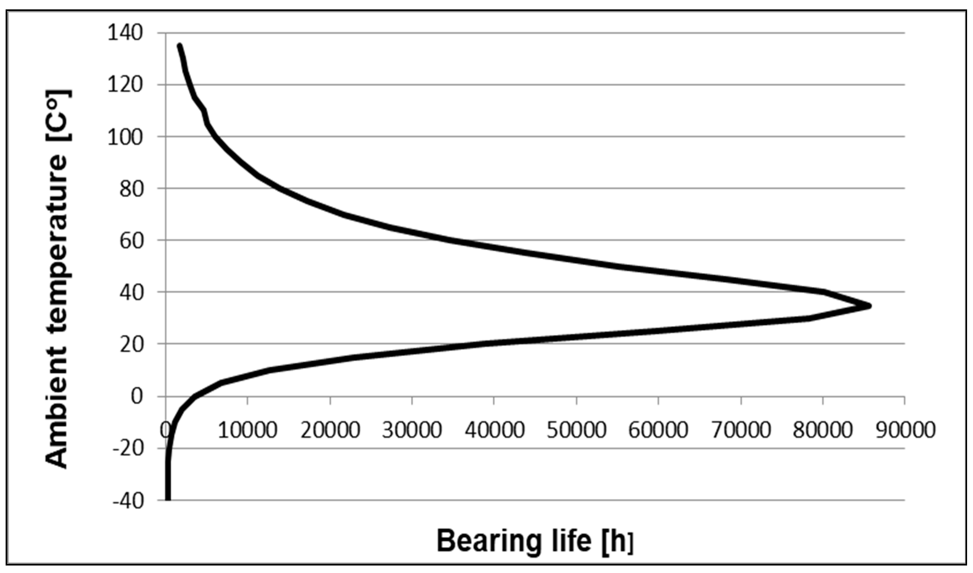
where
—distribution coefficients that are 2534, 2357, 20, 4500;
—ambient temperature (°C);
= 300—lower limit of the bearing durability (h).
The model for predicting the durability of bearings was constructed based on data gathered from companies conducting maintenance works of electric machines. Distribution coefficients were determined empirically by fitting the function to the measured data. To fit coefficients, a linear regression technique was applied:
Data shown in
Figure 8 originate from [
41,
42]. In the case of the change in ambient temperature during the operation of the aircraft commutator, the durability of bearing can be calculated based on the dependence presented above.
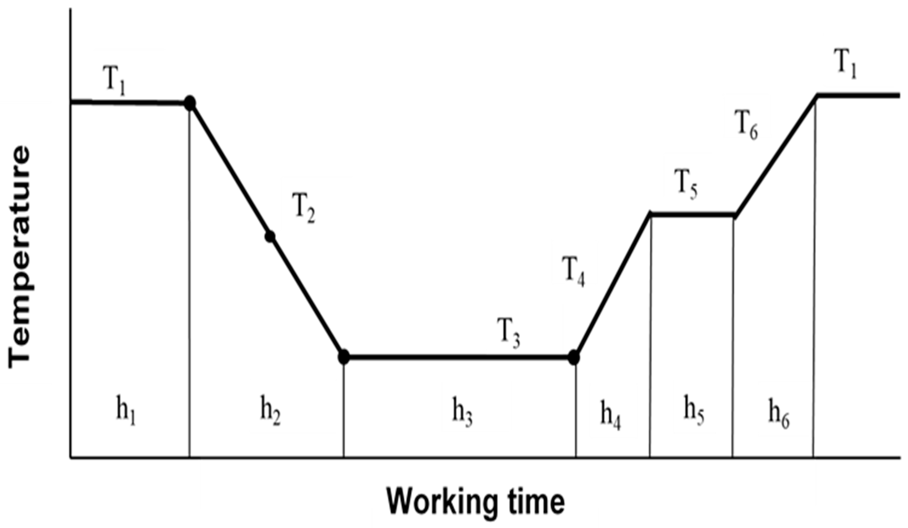
where
—working time in temperature
;
—durability of bearing in
.
Figure 9 presents the changes in ambient temperature while the aircraft commutator is working. The values of temperatures
, and
are calculated as an arithmetic average of extreme temperatures.
The average operating time to failure of bearing was estimated from test results. The bearing failure condition was assumed to be 50%, where
. A natural logarithm from 0.5 was −0.69317. The equation can be written in the following form [
43]:
13. Computing Reliability and Durability of the Starter-Generator Based on the Wear of Brushes
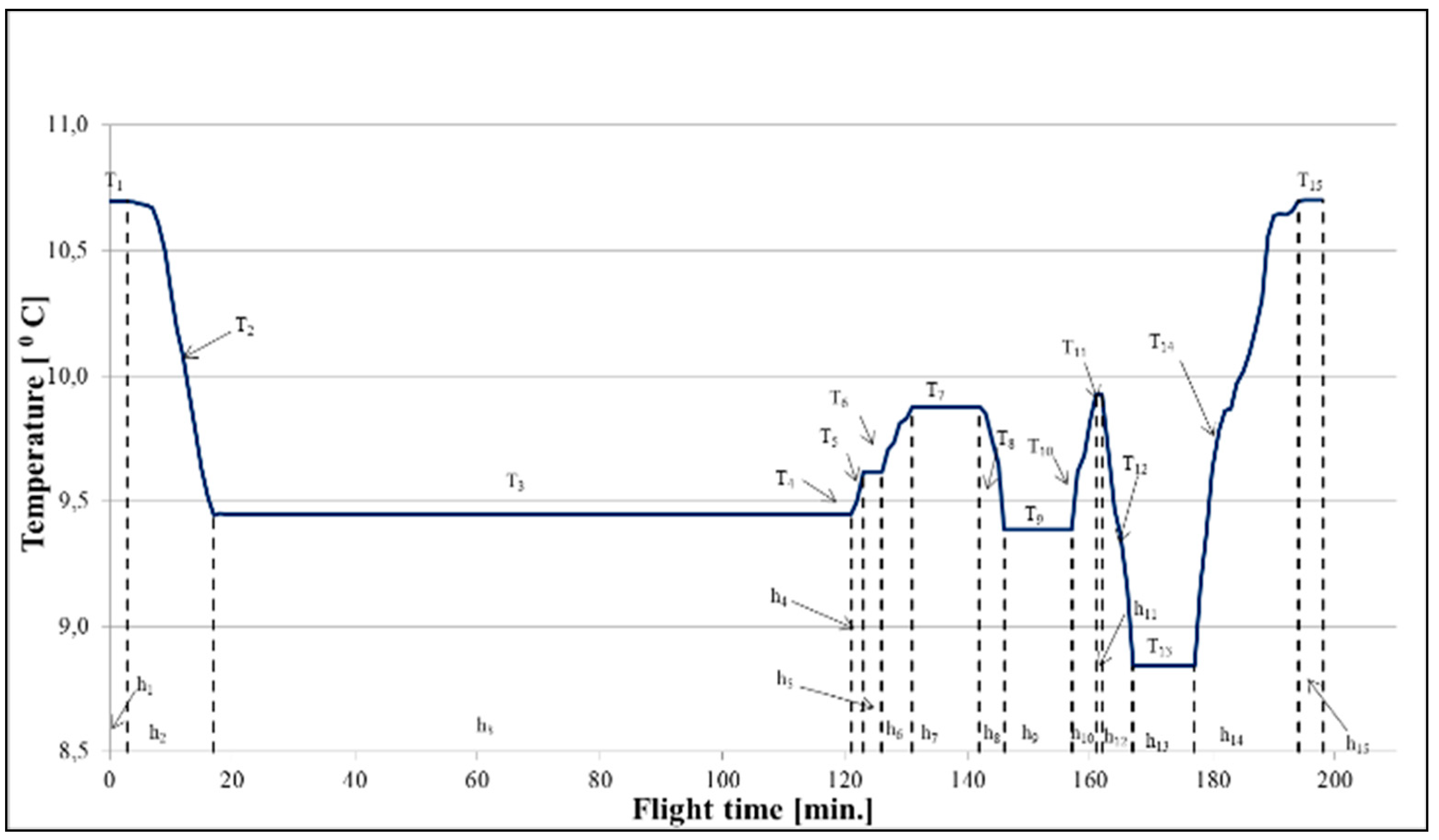
In order to determine the average flight profile of the SW-4 helicopter, data from the flight data recorder were used. It is possible to demonstrate the temperature profile for SW-4 helicopter with the flight profile of the SW-4 helicopter and parameters of international standard atmosphere [
44]. The mean temperature profile for SW-4 helicopter was calculated from 167 flights performed in 2017 [
31]. The mean temperature profile of the helicopter is presented in a graphical form in
Figure 10.
By knowing the values of mean extreme temperatures
, the average temperatures
were calculated based on Equation (35). Then, the durability of bearings in the starter-generator was calculated. The parameter
was computed according to formula 45. Data from calculations are presented in
Table 1. In the next stage of calculations, the durability of the starter-generator bearings was determined providing the operating temperature is not constant. The parameter value was
The bearing’s operating time to failure was
.
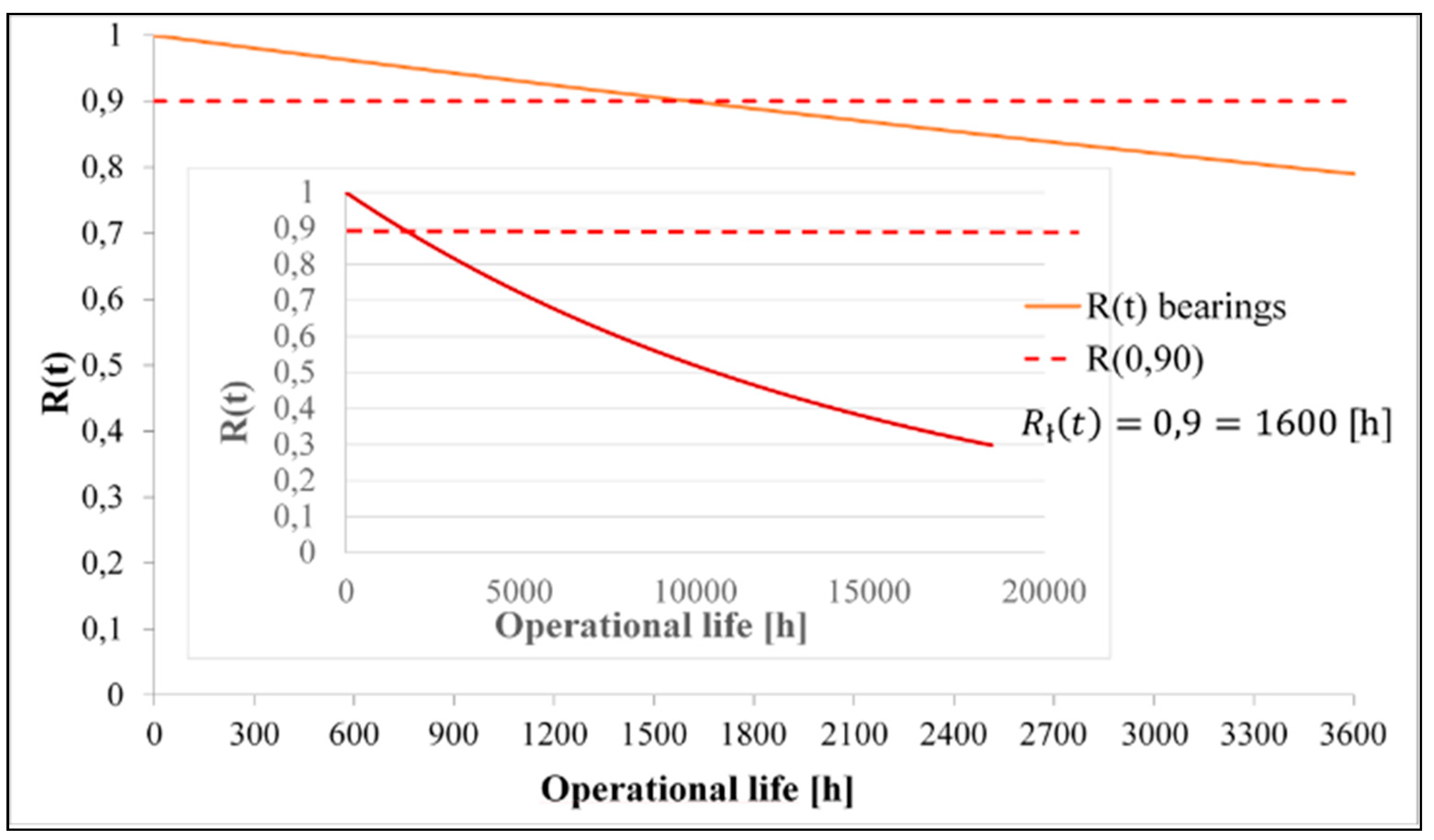
Failure rate of bearings in the starter-generator installed in the SW-4 helicopter is
. With the above data at hand, the graphical form of the reliability function R(t) was determined for the analyzed parameters and it is shown in
Figure 11. Reliability level R(t) = 0.90.
14. Conclusions
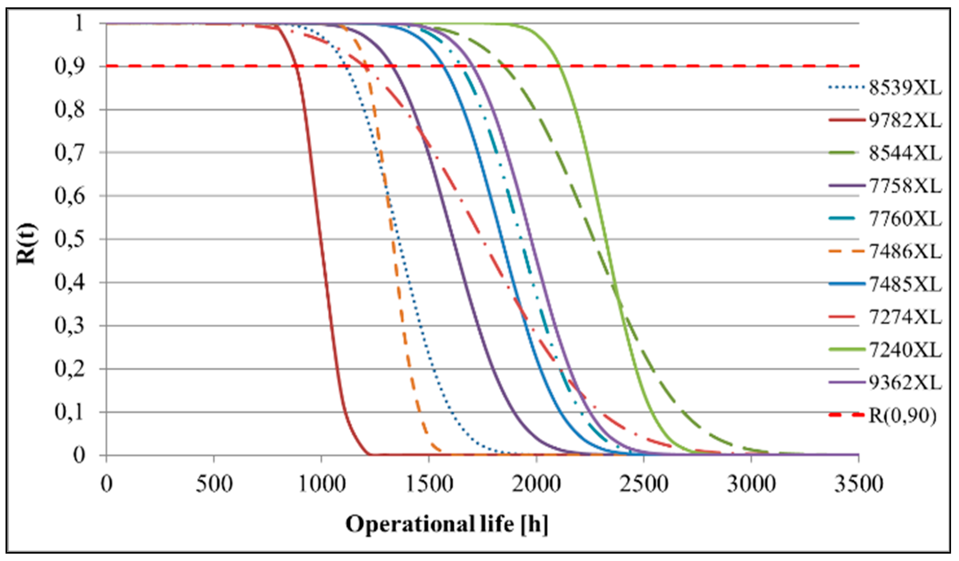
The characteristics of the reliability function R(t) for the diagnostic parameter, which is the wear of brushes in the starter-generator, are depicted in
Figure 12. Calculations were done for 10 starter-generators. Assuming the reliability of brushes at the confidence level of 90% R(0.90), it follows that only on one starter-generator with No. 9782XL, the durability of brushes is below 1000 h and amounts to 880 h.
Table 2 shows a comparison of the brush durability of the tested electric starter-generators. Depending on the number of starter-generators, the values range from 996 to 2321.
While planning the operational process of aviation commutators, it is necessary to determine their durability. Probabilistic models developed to inspect the wear, and ageing processes, can be used to verify diagnostic data. They are useful in developing an operational algorithm for aircraft commutators.
The presented methods of forecasting the reliability and durability of aircraft commutators enable to use maintenance systems in accordance with the state of controlling diagnostic parameters. When maintenance works are completed, the health inspection results are analyzed, and the next period of further operation of the device is estimated. 200SGL129Q starter-generators installed on SW-4 helicopters are operated according to the state system while controlling diagnostic parameters.
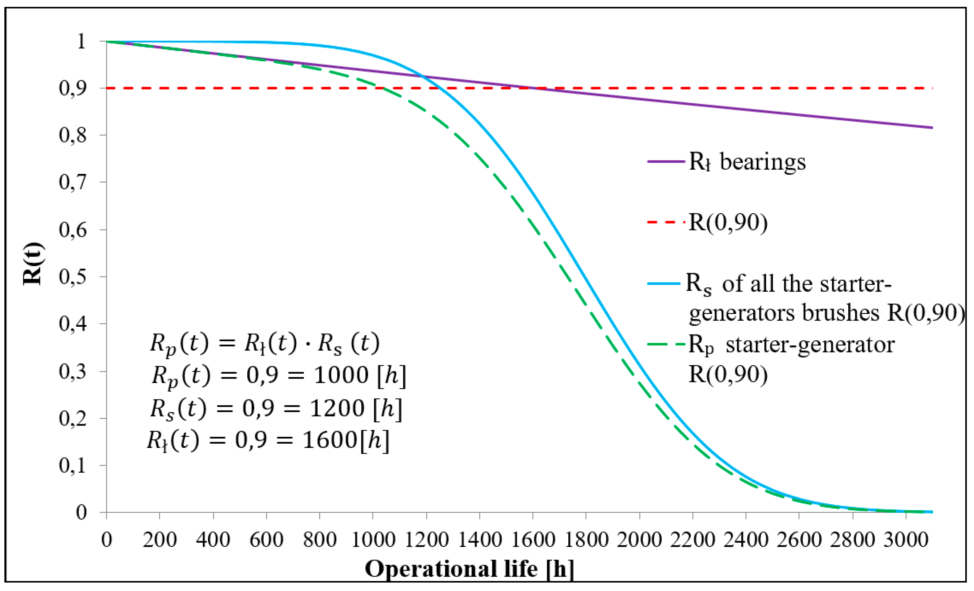
The characteristic feature of this system is that it is possible to eliminate planned major repairs by standardizing only the target periodicity (service life), which is usually limited by the reliability of the most reliable element of the starter-generator. The manufacturer of the 200SGL129Q starter-generator has defined a guaranteed total time of reliable operation, and a specified frequency of maintenance works. Based on the conducted tests and analyses, taking into consideration the diagnostic parameter, it was found that in 1 out of 10 tested 200SGL129Q starter-generators, the brushes did not reach the assumed hourly life (1000 h). The technical condition of the remaining brushes in starter-generators allowed for their further operation (over 1000 h). When testing the reliability of bearings in the starter-generator based on the flight profile, it was shown that the operating time of the bearing until failure is 10,574 h. The reliability of the starter-generator, determined from the reliability of the series structure (diagnostic parameters and flight profile), with the assumed confidence of 90%, allowed to determine the durability of the starter-generator amounting to 1000 h (
Figure 13).
Author Contributions
Conceptualization, W.W. and M.Z.; methodology, W.W., M.Z., J.T. and M.M.; formal analysis, M.M.; investigation, W.W., M.Z., J.T. and M.M.; resources, M.M.; data curation, M.M.; writing—original draft preparation, M.M. and J.T.; writing—review and editing, W.W., M.Z., J.T. and M.M.; visualization, M.M.; supervision, W.W.; funding acquisition, M.Z. All authors have read and agreed to the published version of the manuscript.
Funding
This research received no external funding.
Institutional Review Board Statement
Not applicable.
Informed Consent Statement
Informed consent was obtained from all subjects involved in the Study.
Data Availability Statement
All data are given in the paper. Separately there is no other data.
Conflicts of Interest
The authors declare no conflict of interest.
References
- Zio, E. Reliability Engineering: Old Problems and New Challenges. Reliab. Eng. Syst. Saf. 2009, 94, 125–141. [Google Scholar] [CrossRef]
- Bazovsky, I. Reliability Theory and Practice; Dover Publications: Dover, DE, USA, 2004; ISBN 978-0-486-43867-2. [Google Scholar]
- García Nieto, P.J.; García-Gonzalo, E.; Sánchez Lasheras, F.; de Cos Juez, F.J. Hybrid PSO–SVM-Based Method for Forecasting of the Remaining Useful Life for Aircraft Engines and Evaluation of Its Reliability. Reliab. Eng. Syst. Saf. 2015, 138, 219–231. [Google Scholar] [CrossRef]
- O’Connor, P.; Kleyner, A. Practical Reliability Engineering; John Wiley & Sons: Hoboken, NJ, USA, 2012; ISBN 978-0-470-97981-5. [Google Scholar]
- Strangas, E.G.; Aviyente, S.; Neely, J.D.; Zaidi, S.S.H. The Effect of Failure Prognosis and Mitigation on the Reliability of Permanent-Magnet AC Motor Drives. IEEE Trans. Ind. Electron. 2013, 60, 3519–3528. [Google Scholar] [CrossRef]
- Wang, W.; Jin, L.; Liu, J.; Sun, X. Research on the Application of Supportability Analysis Technology in Ejection Seat. J. Phys. Conf. Ser. 2019, 1215, 12041. [Google Scholar] [CrossRef]
- Wen, J.; Gao, H.; Zhang, J. Bearing Remaining Useful Life Prediction Based on a Nonlinear Wiener Process Model. Shock. Vib. 2018, 2018, e4068431. [Google Scholar] [CrossRef]
- Muetze, A.; Strangas, E.G. The Useful Life of Inverter-Based Drive Bearings: Methods and Research Directions from Localized Maintenace to Prognosis. IEEE Ind. Appl. Mag. 2016, 22, 63–73. [Google Scholar] [CrossRef]
- Jensen, W.R.; Strangas, E.G.; Foster, S.N. A Method for Online Stator Insulation Prognosis for Inverter-Driven Machines. IEEE Trans. Ind. Appl. 2018, 54, 5897–5906. [Google Scholar] [CrossRef]
- Heng, A.; Zhang, S.; Tan, A.C.C.; Mathew, J. Rotating Machinery Prognostics: State of the Art, Challenges and Opportunities. Mech. Syst. Signal Process. 2009, 23, 724–739. [Google Scholar] [CrossRef]
- Tomaszek, H.; Zieja, M.; Ważny, M. A Method for Reliability Assessment of Structural Components of Aircraft and Sea-Going Ships with Taking into Account a Given Failure Generation Model. Pol. Marit. Res. 2016, 23, 83–90. [Google Scholar] [CrossRef][Green Version]
- Wei, W.; Qiao, J.-B. The Generalization of Minkowski Inequality in Two Form. Zhongbei Daxue Xuebao (Ziran Kexue Ban)/J. North Univ. China (Nat. Sci. Ed.) 2013, 34, 109–111, 116. [Google Scholar] [CrossRef]
- Gao, T.; Li, Y.; Huang, X.; Wang, C. Data-Driven Method for Predicting Remaining Useful Life of Bearing Based on Bayesian Theory. Sensors 2021, 21, 182. [Google Scholar] [CrossRef]
- Hinchi, A.Z.; Tkiouat, M. Rolling Element Bearing Remaining Useful Life Estimation Based on a Convolutional Long-Short-Term Memory Network. Procedia Comput. Sci. 2018, 127, 123–132. [Google Scholar] [CrossRef]
- Meeker, W.Q.; Escobar, L. Statistical Methods for Reliability Data; John Wiley and Sons: Hoboken, NJ, USA, 1998. [Google Scholar]
- Ahmad, W.; Khan, S.; Islam, M.M.M.; Kim, J. A Reliable Technique for Remaining Useful Life Estimation of Rolling Element Bearings Using Dynamic Regression Models. Reliab. Eng. Syst. Saf. 2018, 184, 67–76. [Google Scholar] [CrossRef]
- Lee, M.-Y.; Tang, J. A Modified EM-Algorithm for Estimating the Parameters of Inverse Gaussian Distribution Based on Time-Censored Wiener Degradation Data. Stat. Sin. 2007, 17, 873–893. [Google Scholar]
- Noland, J.K.; Leandro, M.; Suul, J.A.; Molinas, M. High-Power Machines and Starter-Generator Topologies for More Electric Aircraft: A Technology Outlook. IEEE Access 2020, 8, 130104–130123. [Google Scholar] [CrossRef]
- Wang, Y.; Nuzzo, S.; Zhang, H.; Zhao, W.; Gerada, C.; Galea, M. Challenges and Opportunities for Wound Field Synchronous Generators in Future More Electric Aircraft. IEEE Trans. Transp. Electrif. 2020, 6, 1466–1477. [Google Scholar] [CrossRef]
- Lee, D.; Choi, D. Analysis of the Reliability of a Starter-Generator Using a Dynamic Bayesian Network. Reliab. Eng. Syst. Saf. 2020, 195, 106628. [Google Scholar] [CrossRef]
- Shantarenko, S.; Ponomarev, E.; Vaganov, A. Performance Control of the Commutator-and-Brush Assembly of the Traction Motor. Transp. Res. Procedia 2021, 54, 854–861. [Google Scholar] [CrossRef]
- SW-4 Helicopter Maintenance Manual; PZL Świdnik: Świdnik, Polonia, 2015.
- Electrical Power System. In Maintenance Manual; PZL Świdnik: Świdnik, Polonia, 2015; Volume 2.
- Technical Manual Job Guide. Airframe and Propulsion Assembly; PZL Świdnik: Świdnik, Polonia, 2020. [Google Scholar]
- Operation Sheet 24.00.7; PZL Świdnik: Świdnik, Polonia, 2005.
- Technical Manual Job Guide Issue 2; PZL Świdnik: Świdnik, Polonia, 2013.
- Lewitowicz, J.; Kustoń, K. Własności i właściwości eksploatacyjne statku powietrznego. In Podstawy Eksploatacji Statków Powietrznych; ITWL: Warsaw, Polonia, 2003; Volume 2. [Google Scholar]
- Zieja, M.; Ważny, M.; Stępień, S. Distribution Determination of Time of Exceeding Permissible Condition as Used to Determine Lifetimes of Selected Aeronautical Devices/Systems. Eksploat. I Niezawodn. 2016, 18, 57–64. [Google Scholar] [CrossRef]
- Tomaszek, H.; Żurek, J.; Jasztal, M. Prognozowanie Uszkodzeń Zagrażających Bezpieczeństwu Lotów Statków Powietrznych; Biblioteka Problemów Eksploatacji; Wydawnictwo Naukowe Instytutu Technologii Eksploatacji—PIB: Warsaw, Polonia; Radom, Polonia, 2008; ISBN 978-83-7204-696-3. [Google Scholar]
- Zieja, M.; Tomaszewska, J.; Michalski, M. Analysis of Lifetime Prediction of the on Board Starter Current. In Proceedings of the 30th European Safety and Reliability Conference and 15th Probabilistic Safety Assessment and Management Conference, Venice, Italy, 1–5 November 2020; Research Publishing Services: Singapore, 2020. [Google Scholar]
- Tomaszek, H.; Jasztal, M.; Zieja, M. A Simplified Method to Assess Fatigue Life of Selected Structural Components of an Aircraft for a Variable Load Spectrum. EiN 2011, 4, 29–34. [Google Scholar] [CrossRef][Green Version]
- Tomaszek, H.; Jasztal, M.; Zieja, M. Application of the Paris Formula with M=2 and the Variable Load Spectrum to a Simplified Method for Evaluation of Reliability and Fatigue Life Demonstrated by Aircraft Components. Eksploat. I Niezawodn. 2013, 15, 297–304. [Google Scholar]
- Ważny, M. The Method for Assessing Residual Durability of Selecteddevices in Avionics System. EiN 2009, 3, 55–64. [Google Scholar] [CrossRef][Green Version]
- Zieja, M. A Method of Predicting Reliability and Lifetime of Aeronautical Hardware with Characteristic Function Applied. In Proceedings of the International Conference, Kaunas Univ. Technol.. Kaunas, Lithuania, 22 October 2015. [Google Scholar]
- Żurek, J.; Zieja, M. The Aging-Processes-Based Forecasting of Service Lives of Selected Items of Aircraft Equipment. J. KONBiN 2008, 4, 7. [Google Scholar] [CrossRef][Green Version]
- Zieja, M.; Ważny, M.; Stępień, S. Outline of a Method for Estimating the Durability of Components or Device Assemblies While Maintaining the Required Reliability Level. Eksploat. I Niezawodn. Maint. Reliab. 2018, 20, 260–266. [Google Scholar] [CrossRef]
- Ważny, M. The Method of Estimating Lifetimes of Aircraft Devices Operating under Ageing-Attributable Wearing Conditions. J. Theor. Appl. Mech. 2015, 53, 981–990. [Google Scholar] [CrossRef][Green Version]
- Dudar, Z. Application of the Limit State Exceedance Time Distribution to Determine the Service Life of Selected Components of Aeronautical Equipment. Master’s Thesis, Military University of Technology, Warsaw, Polonia, 2006. [Google Scholar]
- Aven, T. Reliability and Risk Analysis; Springer: Amsterdam, The Netherlands, 1992. [Google Scholar]
- Military Handbook: Reliability Prediction for Electronic Equipment; Department of Defense: Washington, DC, USA, 1990.
- MIL-STD-704F-CGH-1. Aircraft Electric Power Characteristics; Department of Defense Interface Standard: Washington, DC, USA, 2004; p. 38. [Google Scholar]
- Wilson, D.; Smith, R. Electric Motor Reliability Model; RADC-TR-77-408, Rome Air Development Center, Air Force Systems Command, Griffiss Air Force Base: New York, NY, USA, 1977. [Google Scholar]
- System Informatycznego Wsparcia Lotnictwa Sił Zbrojnych RP. Available online: https://scholar.google.com/citations?view_op=view_citation&hl=en&user=yvhYUr8AAAAJ&citation_for_view=yvhYUr8AAAAJ:yD5IFk8b50cC (accessed on 24 September 2021).
- Reference Atmospheres—An Overview | ScienceDirect Topics. Available online: https://www.sciencedirect.com/topics/physics-and-astronomy/reference-atmospheres (accessed on 23 September 2021).
| Publisher’s Note: MDPI stays neutral with regard to jurisdictional claims in published maps and institutional affiliations. |
© 2021 by the authors. Licensee MDPI, Basel, Switzerland. This article is an open access article distributed under the terms and conditions of the Creative Commons Attribution (CC BY) license (https://creativecommons.org/licenses/by/4.0/).


