1. Introduction
The exponential increase of demand on the wireless data transfer [
1], drives tremendous growth of modern, designed for high-speed data transfer communication systems-like 5G or 6G network. The high demand for mobile data transfer makes old generations of wireless communication insufficient and obsolete. Currently, there are approximately 107 commercial 5G networks across the world, which have in range over
of the total population. Among these 5G networks, 27 are placed in Europe [
2]. Moreover, forecasts given in [
3] show that these numbers will increase rapidly, and the 5G network will support over
of the total wireless connections already in the year 2025.
This dynamic growth of wideband wireless networks, like 5G or 6G, aligns with the constantly increasing presence of power electronic converters in modern society. A recent research indicates that roughly 30% of all electrical power is converted by power electronics equipment. Moreover, there are forecasts that this number will rise to 80% by the end of 2030 [
4]. This phenomena is driven by the increasing number of microgrids and renewable energy sources (RES) in those microgrids, electric vehicles (EV) and factories. However, as each evolution, this also faces some challenges like low versatility of power converters, or high prices of power electronic components and subassemblies, which drives the research over modular [
5] or universal power converters [
6].
There is a link between these two technical trends - a forecast of the new cognitive of power electronics converters, a Power Electronics 4.0. These augmented power converters will be modular devices assembled from Power Electronic Building Blocks (PEBB). They will support new generations of wireless wideband data transfer for control, monitoring, or Machine-to-Machine (M2M) communication. Therefore, research was initiated over a Proof-of-Concept (PoC) of such a modular power electronic converter integrated with a 5G network. The motivation for this study was to evaluate what are potential directions of evolution for augmented power converters, and how wireless communication can be utilized in such devices. Thus, following objectives were defined:
evaluation of potential applications of 5G/6G networks in power electronics,
identification of leading designs for PEBB-based power converters,
performance evaluation of proposed PEBB-based power converter integrated with 5G network.
A detailed description of design process of PEBB can be found in previous work [
7,
8]. In contrast to the recent study in this field [
9,
10], authors consider PEBB module as a subassembly of augmented power converter, rather than power converter itself. The difference between these concepts is further explained in
Section 3. Laboratory testing discussed in
Section 5 was meant to evaluate performance of PEBB-based power converter, as well as to identify main challenges related to integration of power electronic equipment with wireless network.
This paper is organized as follows: in
Section 2 discussion over potential applications of power electronic converters integrated with a 5G network is conducted. Afterwards, in
Section 3 the PEBB concept itself and leading types of PEBB-based power conversion systems are presented. Next, in
Section 4 a PoC of PEBB-based power converter integrated with 5G network is presented. Test results are presented afterwards in
Section 5. Summary and conclusions are given in
Section 6 and
Section 7 respectively.
2. Potential Applications of 5G Network in Power Electronics
As presented in
Table 1, 5G and 6G communication networks leave far behind previous generations of wireless communication in terms of data bandwidth, latency, and reliability.
In the case of power electronics, integration of multiple devices within the 5G network will offer the best benefits in fields where usage of traditional mediums, like cable or fiber optic connections, would be insufficient, impractical, or expensive. Thus, the wireless data transfer will present outstanding performance in integrating devices dispersed in the great or hardly accessible areas. Moreover, as presented in
Table 1, a 5G network offers far greater possibilities for fast data transfer than LTE or 3G. This enables real-time exchange of large data sets, which is a very foundation of multiple futuristic concepts, like e.g., Demand-Side Control (DSC) [
11], model-based or machine learning-based condition monitoring [
12,
13], energy exchange [
14] or vehicle-to-everything integration (V2X) [
15,
16,
17]. Thus, for discussion over potential applications of power electronic converters integrated with 5G network, the following approach was introduced: in
Section 2.1 discussion focuses on potential applications of wireless communication in power electronics, while in
Section 2.2 analysis covers most promising applications of broad-band data transfer in power electronics.
2.1. The Wireless Communication in Modern Power Electronics
One of leading examples of the complex system spread over a great area, which consists of numerous devices (actors), is agriculture. As presented in [
18], future large scale farming - described with the concept of Agriculture 4.0. —will heavily rely on the Internet of Things (IoT) and Unmanned Autonomous Vehicles (UAV), such as autonomous combine-harvesters, drones, or self-driving soil analysis stations [
19]. Thus, tight integration of all components and subsystems in a single wireless network is key to ensuring the whole farm’s highly efficient, reliable, and unstopped operation. The following example of a power electronic converter integrated with a 5G network for farming compliant with
concept is a self-sustainable,
PV-powered station for soil parameters monitoring [
20]. Other applications of such power converters could be charging stations for UAVs, and drones [
21], small or medium Renewable Energy Sources (RES) (like vertical wind turbine [
22]) for island operation of particular subsystems. In these examples, integration with the 5G network would enable online data logging, condition monitoring, and failure reporting.
Another excellent example of a system dispersed at the large, hard accessible surface is a border control system, which may consist of UAVs and drones [
23] or autonomous surveillance systems [
24]. Just like in the case of the
, it is expected that drones or surveillance systems will be integrated with the 5G network and - power electronics used by border control services. Potential applications of such power electronic converters are charging stations for land and air UAVs or power converters for RES and Uninterruptible Power Supplies (UPSs), designed to increase power quality or ensure reliable operation of border control systems.
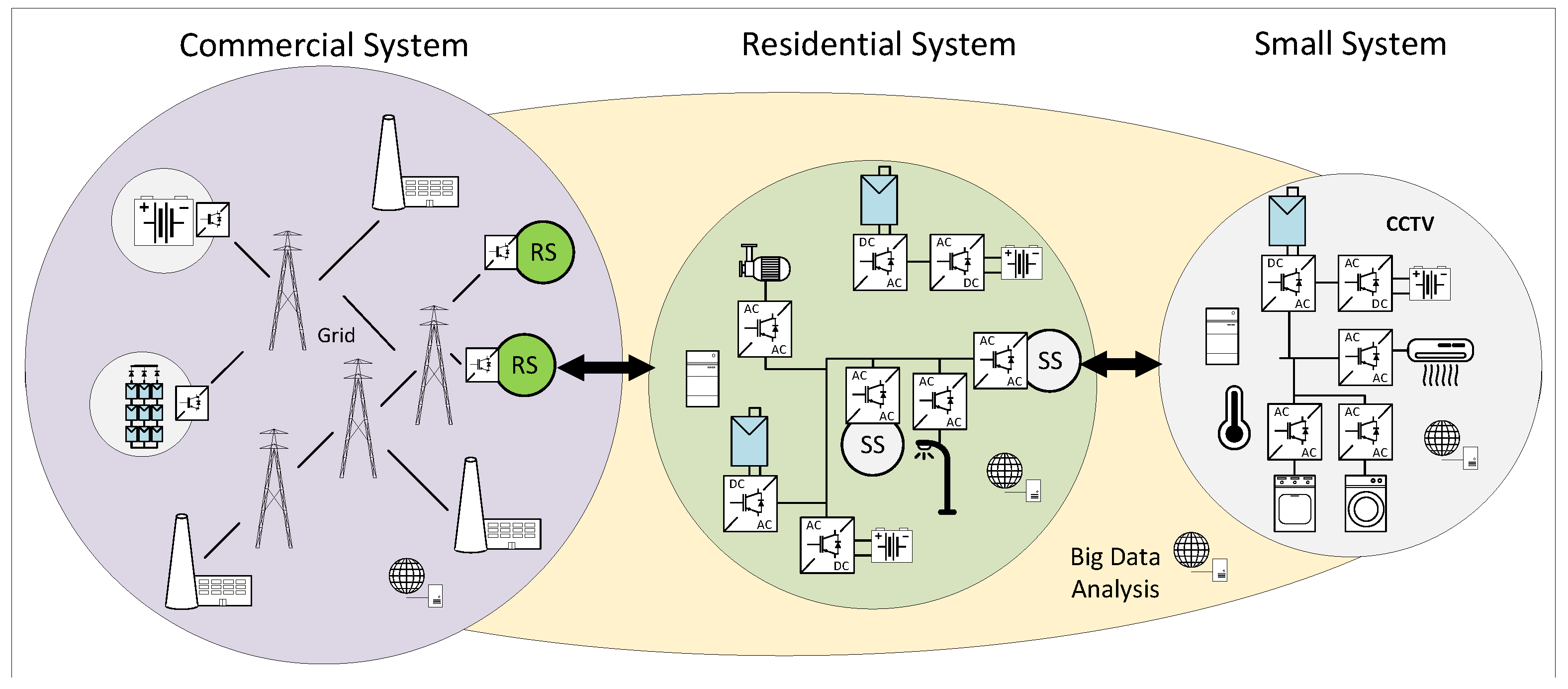
The last good example of a complex system, which may gain a lot from the wireless data transfer, is the electrical power grid itself. Power transmission and distribution lines are spread over thousands of kilometers, connecting power plants and RES with electrical substations or all-kind electric loads. In this particular application, the wireless data transfer offers substantial advantages for either small (e.g., single of few houses), residential (e.g., neighborhood), or commercial grids. A simplified graphical representation of commercial, residential, and small intelligent power conversion systems is presented in
Figure 1. The smallest example of a smart power conversion system can be a nano-grid equipped with a few PV panels and an energy storage [
25], which would be integrated with other services for smart house infrastructure [
26]—e.g., heating, air conditioning and ventilation. In this case, the primary purpose of integrating household electronics and power electronic converters within a single 5G network is to increase the convenience of maintenance and management of smart house facilities. An excellent example of an intelligent residential microgrid may be a small production facility, farm, or neighborhood consisting of multiple smart houses. A significantly larger area than in a single household allows for a larger generation of electric power from RES. Moreover, such facilities have far more complex infrastructure than a single household - it consists of e.g., street and external lighting, electrified drainage systems, irrigation systems, emergency and fire protection systems, security, and others. Integration of these systems and power electronics equipment within a single network would allow for centralized control and ease facility management, e.g., by predictive maintenance and hence - reliability improvement. Thus, the benefits of integrating multiple devices in a single wireless network increase proportionally to the size of the microgrid or the complexity of residential infrastructure. In the case of large, commercial grids, broad utilization of wireless communication in electrical engineering is one of the fundamentals for the EnerNet [
27,
28], which describes the idea of intelligent routing of electrical energy between sources and loads. Moreover, direct data transfer between various participants of the electrical grid can also be used to increase its stability and reliability, e.g., by mitigation of harmonics introduced by RES [
29] or imbalance in low voltage distributed networks [
30].
2.2. The Wide Bandwidth Data Transfer in Modern Power Electronics
Beside examples given in the previous subsection, 5G offers a lot for modern power electronics, thanks to its superior performance compared to old generations of wireless data transfer techniques. One of the leading examples of concepts, which requires fast and reliable data transfer is DSC. The next great example is energy trading, and consumption management [
14], which allows minimizing electrical bills for intelligent micro-and nano-grids. However, it offers great potential for residential and commercial power conversion systems.
Next, the model-based or machine learning-based condition monitoring will significantly increase the reliability and availability of electrical equipment (e.g., drives, inverters) integrated within the 5G network. As an example, measurements performed in power converter (e.g., temperatures of power semiconductor devices, currents, voltages, etc.) or total count of thermal cycles could be compared with proper reliability model [
31], to estimate the Remaining Useful Lifetime (RUL).
Other concepts which will benefit from the 5G-compatibility of power electronics are Vehicle-to-Grid (V2G), Vehicle-to-Home (V2H), Grid-to-Vehicle (G2V) or Vehicle-to-Vehicle (V2V) [
32,
33]. Similar to the DSC and EnerNet, these concepts enable and enhance the source-load coordination, which significantly increases the electric system’s stability, reliability, and robustness. For example, a vehicle heading to the charging station or home could send information to the grid operator about the forecast for power and energy demand. Among these examples, the V2V is especially interesting, as high baud rate wireless communication allows to exchange of large packets of data between vehicles, e.g., to determine which unit needs access to the charging station the most. Moreover, minimal communication latency is essential for autonomous driving, which heavily relies on the V2V concept. As an example, a vehicle may transmit the distress signal to neighboring vehicles during emergency braking to slow them down and avoid the multi-vehicle collision, which is extremely dangerous and-unfortunately-typical for the modern expressways [
34].
Last innovations, which will significantly benefit from the integration of power electronics with 5G network, are condition monitoring, failure prediction, and preventive maintenance, especially those techniques which are based on the Big Data analysis. In such an application, a power electronic converter transmits a large amount of data (e.g., voltage, current, and temperature measurements) over the 5G network to the dedicated server, where they are processed with e.g., machine-learning algorithm [
35,
36,
37]. The alternate approach is a digital twin concept [
38], which assumes to compare measurements recorded in real devices with results of thoroughly adjusted electro-thermal models. Comparison of measurement and simulation results allows for distinct deviations of electrical signals, which can indicate forthcoming failure.
Examples presented in this section show a variety of applications, where the 5G network will enable new functionalities to enhance the performance of power electronic converters. This indicates that the 5G-compatibility may be a key feature of future power electronics equipment. Moreover, this justifies the initiation of research over PEBB-based power electronic converter integrated with a 5G network.
3. Concept of the Power Electronic Building Block
The Power Electronics Building Block (PEBB) concept was developed by the U.S. Navy’s Office of Naval Research (ONR) in the XX century [
39]. That study was meant to develop a universal, stackable power converter, which could be used to develop a large scale power systems, by series-parallel connection of PEBB units. It was assumed that modular design will benefit power conversion by e.g.,: loss and size reduction of power electronics, manufacturing cost reduction thanks to the scale effect, reduction of the engineering effort thanks to re-usage of components and functional modules, or increased on-site serviceability of power conversion systems [
40,
41]. Moreover, in modular power conversion systems, PEBB module is considered as a Line Replaceable Unit (LRU)—a module designed especially to enable a quick replacement on-site by low qualified staff [
42].
As it was presented in [
39,
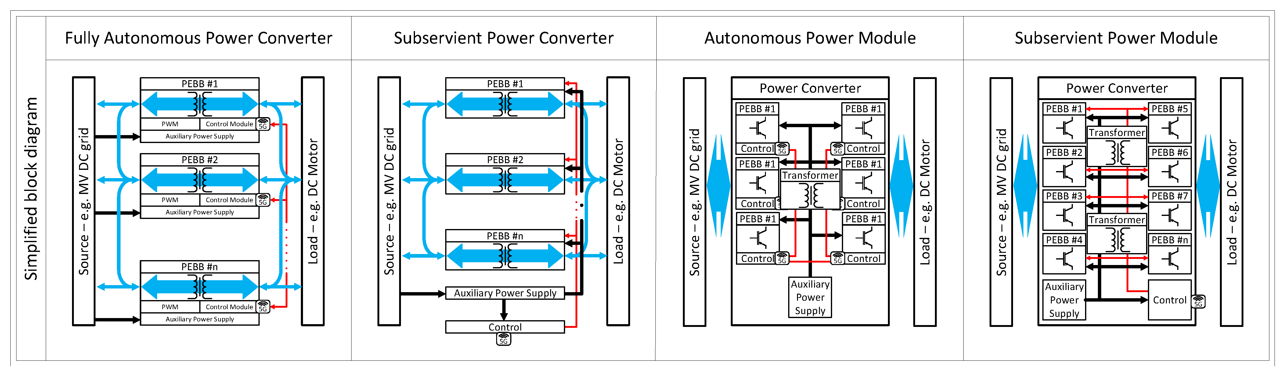
43], the main goal of the PEBB concept is progressive integration of power modules, gate drivers, passive and auxiliary components into functional modules (blocks), with well-defined functionality and interfaces. Such standardized, plug-and-play blocks could be used to build large-scale systems for various applications in the same way as modern computer subassemblies are used to develop personal computer or server clusters. There are multiple concepts and technical implementations of PEBB, prepared by various researchers and industrial participants of the power electronics market. As depicted in
Figure 2, these concepts can be divided into four subcategories, and each of these solutions offers different benefits and challenges for the designer of a power conversion system. Closer analysis of various concepts of PEBB-based power converters or power conversion systems indicates, that there is another potential application of wireless data transfer in such devices: 5G or 6G network can be used for communication between PEBB-modules. In the case of Subservient Power Converter (SPC) and Subservient Power Module (SPM), wireless communication can be used in the same way as discussed in
Section 2.
First approach, presented in [
6], is the design of a Fully Autonomous Power Converter (FAPC) with well-standardized input/output terminals, communication protocol, and housing. Such an approach is most compliant with the original definition of PEBB or LRU. From the point of view of a power conversion system designer, the main benefits of such a standalone converter are:
plug-and-play design, which greatly eases maintenance or repair—especially for low qualified staff,
Hot Swap ability,
great scalability, as each PEBB has the same insulation requirements.
Thus, this concept suits well for any safety-critical or high-availability application, e.g., underground mining, distributed power generation, or ship on-board electric grids. Although typical examples of such PEBB-based power conversion systems are for medium voltage applications, recently, there are more commercially available low power solutions (e.g., ). The next advantage of this approach is the ability for the gradual development of a power conversion system. As FAPC is basically a standalone power converter, it enables the ability to gradually increase the total voltage/power rating of power conversion system by connection of additional PEBB modules. Thus, it significantly lowers the investment entry threshold, which is crucial for non-commercial, or small capital users of power electronics equipment. However, this approach also have disadvantages, like: low power density (volumetric and gravimetric) or high overall cost of PEBB and PEBB-based power conversion system. The last drawback is caused by duplication of certain functional modules in each PEBB, like: control board, Auxiliary Power Supply (APS), high-frequency transformer, etc. The next major flaw of FAPC-based power conversion systems is rather complicate test and start-up procedure. It has to be done with high voltage present on input terminals of the power conversion system, as each PEBB is a standalone power converter, which requires the input voltage to power up itself. At last, such an approach causes control-related issues, due to current and power sharing between PEBBs.
Second design type of PEBB is a semi-autonomous, Subservient Power Converter (SPC). In this concept, building blocks may not be equipped with sophisticated control boards or energy harvesting units. Thus, they have to be supplied and controlled by an external APS and System Control Unit (SCU), which significantly reduces the scalability of the power conversion system. For example, the maximum source voltage of the PEBB stack would be limited to the insulation rating of the APS module, the maximum amount of PEBB units would be limited to the power rating of the APS module or control board abilities (e.g., amount of optical outputs). A similar concept is the implementation of both distributed and centralized control algorithms, as it was presented in [
44]. This approach allows reducing the overall cost of power conversion system significantly, thanks to the reduction of unnecessary, redundant functional modules (e.g., control boards, APS, etc.), while keeping plug-and-play design compliant with LRU definition. An additional benefit of a centralized APS module is the ability to start up the whole stack-up of PEBB modules without high voltage on input terminals. The leading trade-off in this approach is lower scalability than the previously described concept. In this case, the maximum rating of the power conversion system will be limited by insulation rating in the central APS module, total slaves count of the centralized control module, the capacity of the data bus linking power and control modules, and other factors.
Alternate concept for PEBB design in preparation of highly integrated, Autonomous Power Module, instead of the standalone power converter, as it was presented in [
45,
46,
47]. In this approach, PEBB modules are used instead of developing a single high voltage, high power converter than a large-scale power conversion system. This allows for significant cost reduction of development and manufacture of high power converters, thanks to high volume production and re-use of functional modules while keeping high power density of end product and design well-tailored to the target application requirements. Such a modular approach, typical for multilevel converters, greatly eases service and maintenance of power electronic converters. However, this approach has some significant flaws. The first one is more complicated service and maintenance (e.g., PEBB replacement) than a fully autonomous system and lack of hot-swap ability. If any PEBB module fails, the whole power converter has to be shut down for service action, which has to be done by well-qualified staff. It would require a more complex action than simply unplugging the malfunctioning device from the power conversion system cabinet. Another disadvantage is the limited possibility for modification or development of operating PEBB-based power converter.
Main difference between the above-described Autonomous Power Module (APM) and Subservient Power Module (SPM) concept is the level of integration of PEBB modules. In contrast to APM, in this approach, PWM signal is generated and distributed between PEBB modules by a single control board. This allows for further cost reduction of PEBB modules, thanks to a more straightforward design. Both APM and SPM concepts have the same advantages and disadvantages; however, the SPM approach offers a higher potential of development thanks to similarity to the architecture of the modern personal computer. Such well-standardized modules could be used for the rapid growth of either:
PEBB-based power supplies, e.g., for automotive application [
48], aircraft electrical propulsion systems [
49], power routers [
47],
and non-commercial power conversion systems, e.g., Maximum Power Point Tracking (MMPT) converters, Uninterruptible Power Supplies (UPS).
The second niche is especially interesting in the scope of the EnerNet concept.
However, this idea faces many challenges, like lack of standardization of power converters packaging, output terminals, power ratings, etc. Thus, both commercial and non-commercial users of power electronic equipment are forced to develop own, customized solutions or third-party power converters. Neither option is ideal. In the case of customized power converters, development of new power converter takes time and resources; thus, it is not a cheap solution. In the second case, user has to find a third party solution closest to his requirements, which usually causes a trade-offs in the case of size, efficiency, power factor, and others.
4. Materials and Methods
The SPM concept was found as most suitable for future generations of augmented power electronics converters. As discussed in [
7,
8] the half-bridge topology was found as the optimal solution for PEBB module, as such topology assures the highest
"configurability". The
"configurability" or
"flexibility" is understood as ability to assemble various power electronic converter topologies from PEBB modules. A detailed discussion over the design procedure of the PEBB module was already presented in [
7,
8]. Thus, this paper focuses on the whole PEBB-based power converter, evaluation of its performance, and challenges related to incorporating wireless communication over 5G network into power electronic converter.
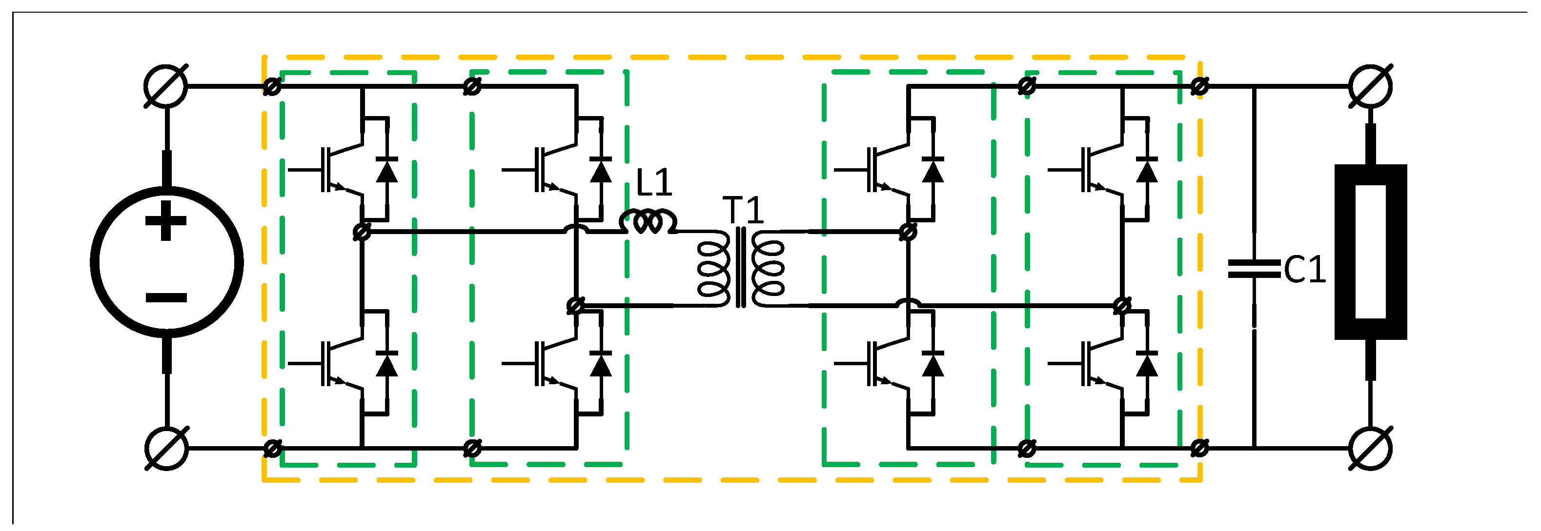
The PoC of PEBB-based power converter integrated with a 5G was designed in a Dual Active Bridge (DAB) topology, due to the simplicity and “time to prototype”. This design can be further modified by adding more PEBB modules, in order to e.g., develop of a single- or three-phase active rectifier or inverter. In this approach, the DAB acts as a core of modular power converter, as presented in
Figure 3. Bill of materials and technical parameters of discussed PoC are presented below:
switching frequency: 10 kHz
rated voltage: 300 V
rated power: 3 kW
power semiconductor devices: SiC Cascode
MOSFET driver:
DAB output capacitance : 1000 uF
Transformer turn ratio: 1:1
Inductor inductance: 25 uH
DAB transformer inductance : 1.5 mH
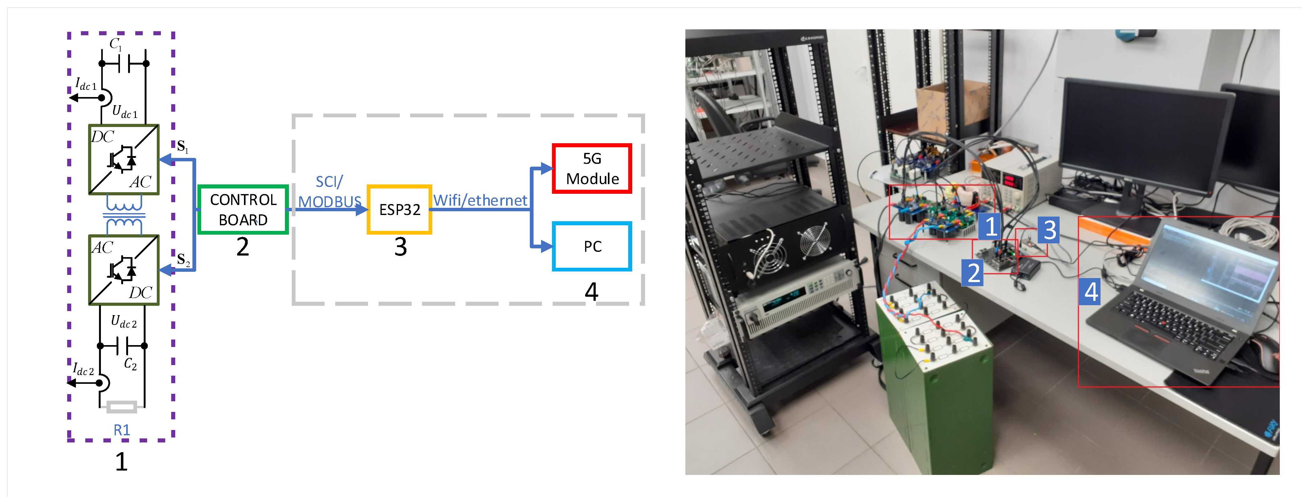
During the design phase, it was found that none of the top manufacturers of electronic equipment (e.g., Texas Instruments, Analog Devices) does not offer an evaluation board dedicated for power electronics (e.g., with expanded PWM generation), already equipped with the 5G modules. There are evaluation boards dedicated to developing 5G networks; however, they are not meant for power electronic applications. Thus, developing a dedicated control board was required - equipped with an adequate microprocessor and wireless communication module. However, the following approach was chosen for evaluating the concept of a power electronic converter integrated with the 5G network. To minimize the time and effort required to start up the fully functional PoC, it was assembled from:
control board designed in Institute of Control and Industrial Electronics at Warsaw University of Technology, based on the microcontroller from Texas Instruments,
communication module from Espressif Systems,
the SCI/USB converter designed in Institute of Control and Industrial Electronics at Warsaw University of Technology,
personal computer,
5G router.
Power electronic modules (1)—e.g., PEBB modules, voltage-current measurement modules, DC-link, and transformer-exchanges data, like measurements or control signals for power MOSFETs, with control board (2). The Control Board realizes multiple functions: digital signal processing, control loop execution, generation of the PWM signal, and all other key functionalities. Two alternate solutions for communication with PEBB-based power converter-PC-router 5G, were tested: the wireless data transfer over WiFi, as presented in
Figure 4, and classic wire-based connection of the control board with the USB cable, as presented in
Figure 5. In both cases, the control board (2) exchanges data with the peripheral’s driver (3). In the current solution, the control board transmits key electrical measurements (e.g., output voltage, output current) to the personal computer (4), which acts as the Human-Machine Interface (HMI) with user interface in the form of the prompt window. The same protocols can be used for communication with the 5G modem.
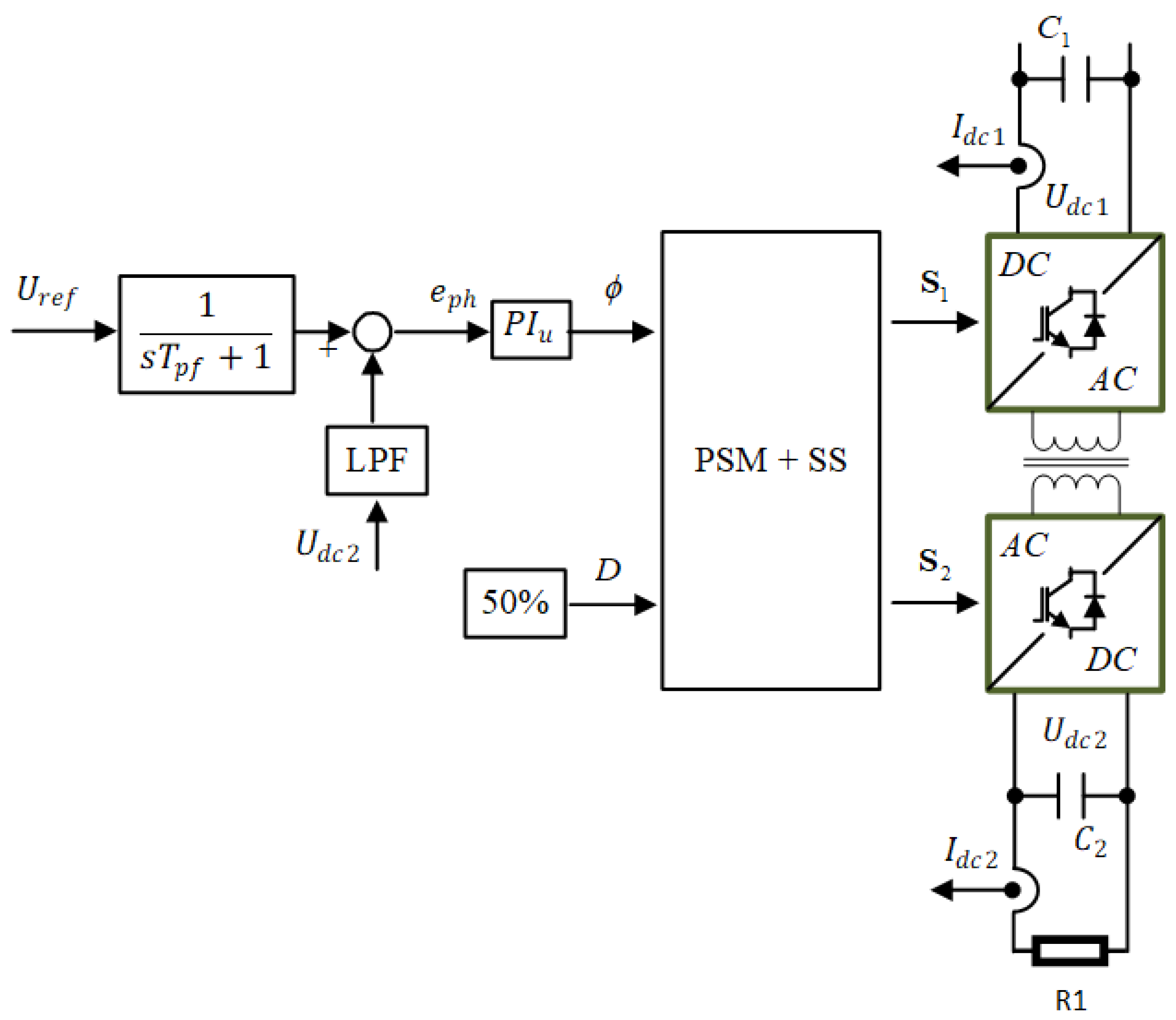
Control method used in presented PoC is the Single Phase Shift Modulation (SPSM). As depicted in
Figure 6, control algorithm consists of two main modules:
The calculation of the appropriate phase shift in the range from 0 to 2 Pi is discussed in [
50]. Then it goes to the modulator block in which the classic SPSM control system [
51] is implemented, selected for this implementation due to its simplicity and good performance characteristics in dynamic states. The module is meant to get desired phase-shift between primary and secondary side of high frequency transformer, for given reference current on primary side to precise control of power flow. DAB control schematic presented on
Figure 5.
The considered system works as a voltage source in the range of 200–400 V, transformer ratio 1:1, primary side power supply 300 V. The implemented system works with a resistive load with a power of up to 3 kW. The layout allows simple configuration and bi-directional operation.
5. Results
The main criteria defined for performance evaluation of PEBB-based power converter were:
As these parameters were expected to be compromised in the PEBB-based design. In typical state-of-the-art power converter design is optimized to minimize current loops or to reduce any stray inductances which may affect switching conditions. However, in the case of PEBB-based systems, mechanical dimensions are enforced by shape and size of PEBB module. Thus, lenght of current loops and parasitics shall be higher in PEBB-based power converters than in the case of state-of-the-art solutions. Fast measurements (e.g., voltage waveforms) were performed with differential probe, current probe and oscilloscope. The efficiency measurement was done with the set of multimeters, based on the DC signals measurement.
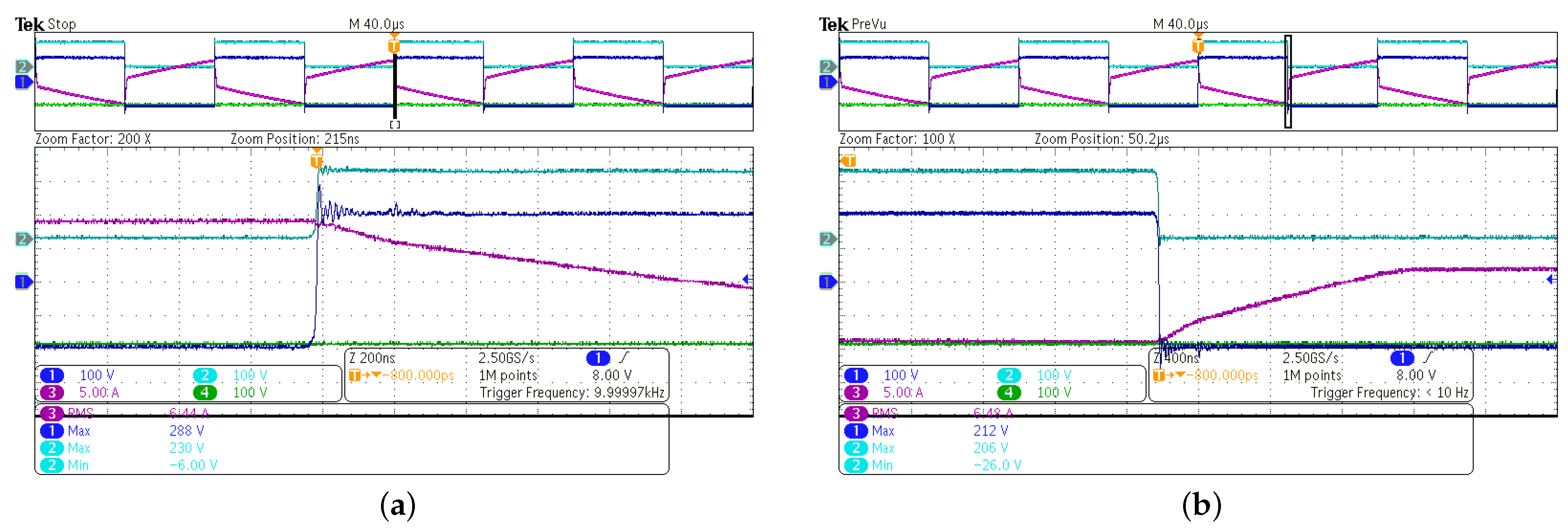
Although DAB power converters typically operate in phase-shift, which ensures zero-voltage-switching (ZVS) or quasi-ZVS operation, drain-source voltage waveforms were the subject of special attention. As presented in
Figure 7a presents rising edge of voltage waveforms and (b) falling edge. Voltage waveforms are free from ringing or voltage overshoots, which could damage
MOSFET device [
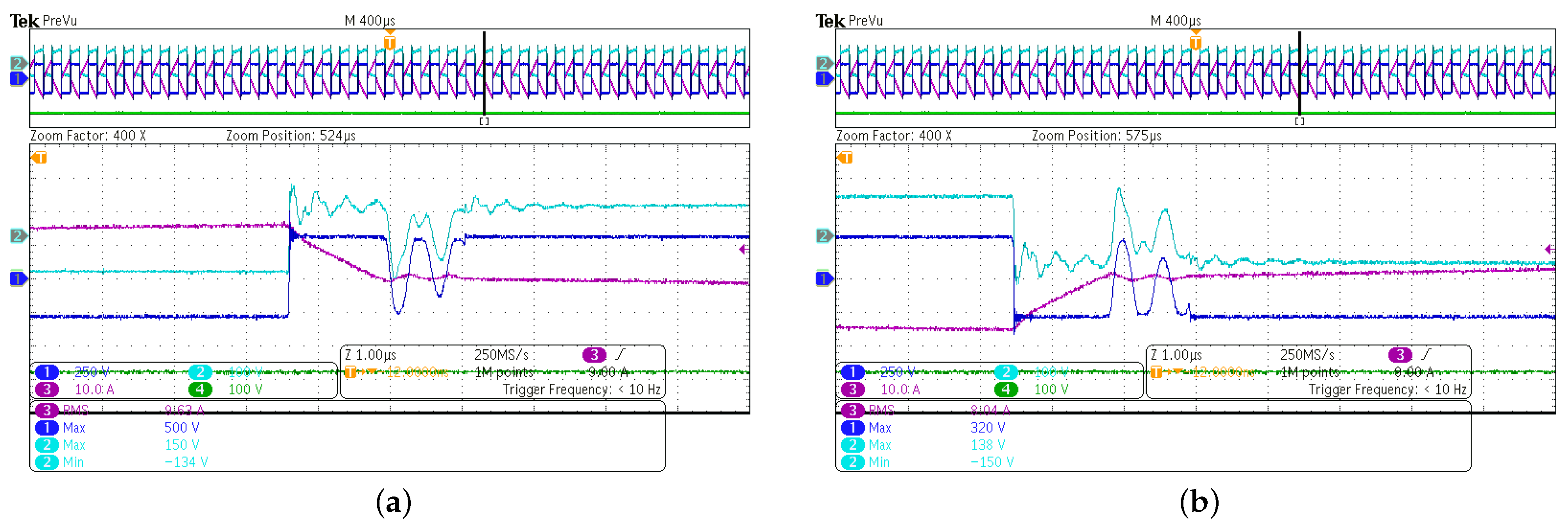
52]. This suggests the proper design of the PEBB module, which ensures a very short commutation loop and low stray inductance. Voltage collapse and spike, depicted in
Figure 8 a presents rising edge of voltage waveforms and (b) falling edge. The second waveforms indicates presence of the resonance between parasitic capacitances of high frequency transformer and stray inductances due to likely DT problem. The problem exist only with small phase shift angle, and the effect rises with higher voltages. This phenomena was investigated in [
53], and it will be improved in alpha version of PEBB-based power converter integrated with 5G network.
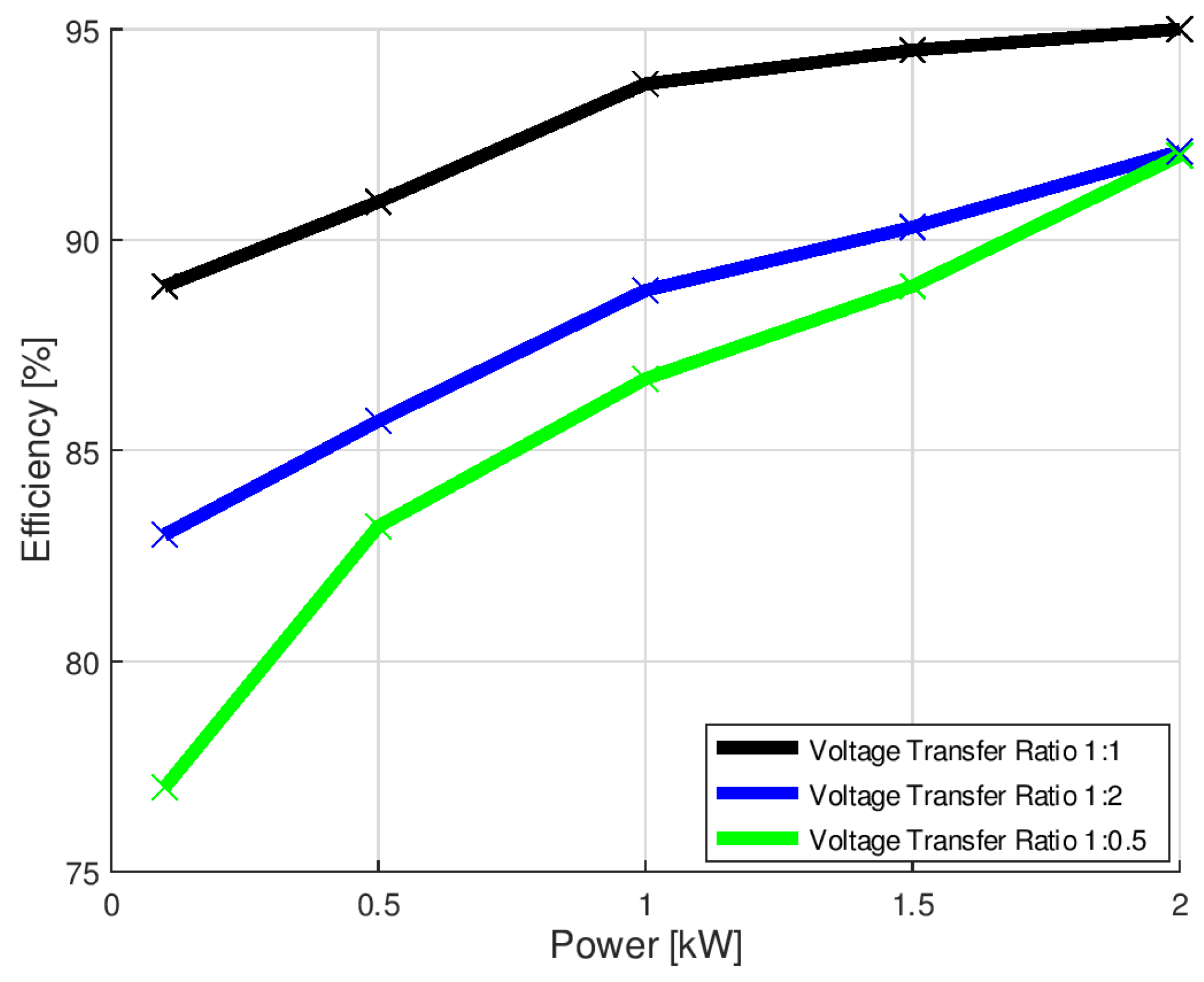
Afterwards, performance was evaluated on the following - topology - level. At first, the power converter’s efficiency was measured for three voltage transfer ratios: 1:1, 1:2, and 1:0.5. As depicted in
Figure 9, the peak efficiency of the proposed PEBB-based power converter was found a bit lower than state-of-the-art Dual Active Bridges. In presented PoC, it was
, in contrast to
presented in [
54]; however, this result was found as satisfactory. A slightly lower efficiency was considered as:
trade-off between outstanding performance and increased modularity, which offers such benefits like e.g., serviceability or lower manufacture cost,
effect of low power rating of power converter, which makes switching losses, driver losses or losses in strain resistances much more visible in efficiency measurement.
trade-off between outstanding performance and increased modularity, which offers such benefits like e.g., serviceability or lower manufacture cost. Closer analysis of test results depicted in
Figure 9 shows that efficiency plummets if the voltage transfer ratio is different than 1:1, especially for low power levels. Thus, although the difference in efficiency for 2 kW barely reaches
, it rapidly increases to
at 100 W.
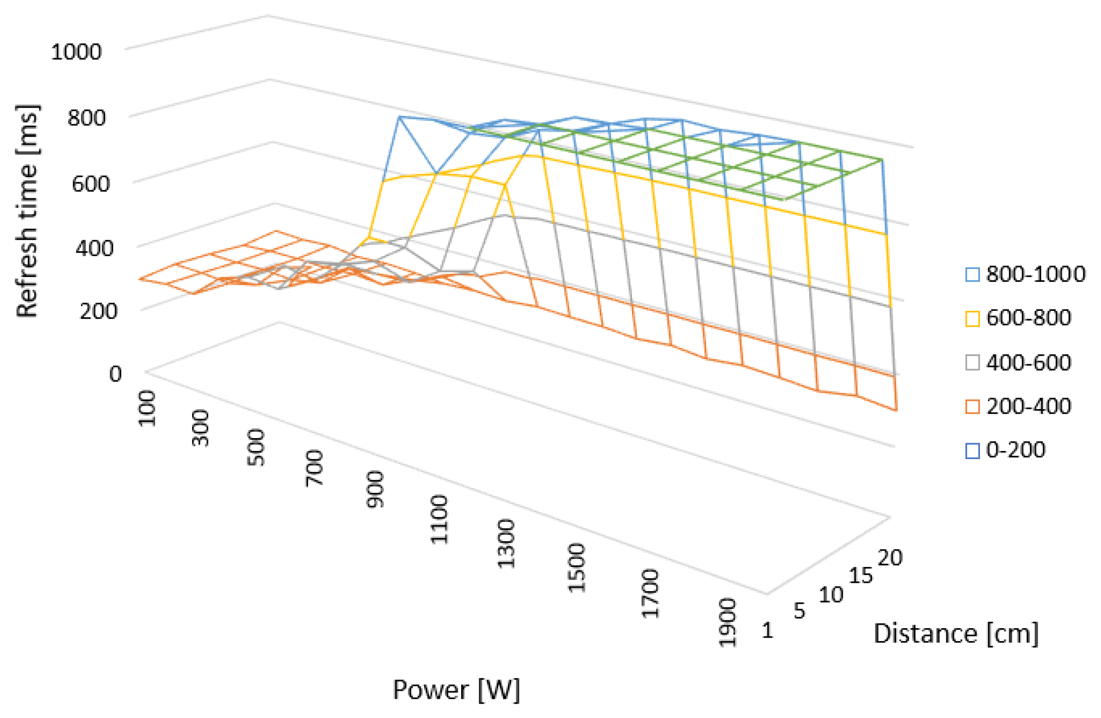
The next step of laboratory testing, was integration of discussed PoC with a 5G network. During this process, a few technical challenges were encountered. The first one was the susceptibility of the
ESP32-wroom32D module for electromagnetic noise. In the configuration presented in
Figure 4, as long as communication module (3) was placed between power converter (1) and control board (2), it was not possible to establish communication. This issue was found at a relatively low power level, roughly 0.4 kW transferred from input to the output of the PEBB-based DAB power converter, when refresh time of parameters recorded on PC started to increase. During operation with 70–80% of rated power, wireless communication was found entirely not responding. To restore proper function, it was found that the distance between the source power converter and communication module should be no less than 20 cm. However, this temporary solution was meant only for further laboratory testing, especially that for different power levels or other types of power converters, electromagnetic noise emission may be significantly higher. Thus, for practical utilization of wireless communication modules in modular power supplies a proper shielding between the power converter side and low-voltage electronics must be ensured.
The next challenge was the relatively high refresh time of the HTTP website displaying parameters transmitted from the control board. It was found that to transfer data from a PC or 5Ghost to a control panel, like a command to start up a power converter, roughly 300 ms was required. In this time full procedure of communication starts from establishing communication, endpoint service and ends with closing the session was proceed. Detailed analysis showed that the limitation is not in the SCI communication between control board (2) and module (3). Measurements or commands (e.g., turn power converter on, turn power converter off) are exchanged in the frame, with 100 kB/s baud rate.
Communication between the server (ESP32) and the client is conducted using the HTTP protocol. This protocol allows downloading data such as HTML source files as a typical server-client protocol, where a web browser issues the request. In our case, part of the user-device interface is implemented in two variants: server-client and server-a proxy-client, using API based on HTTP is the XMLHttpRequest. The data sent is in binary form; JSON has been abandoned due to additional delays. This interface exchanges requests and responses with each other. Typical requests issued by the system we designed are mainly POST due to increased transmission reliability and security, such as:
,
,
,
, etc. The average time of handling request-response communication is 50 ms
Figure 10. The time needed to provide all communication, sending requests, and data takes an average of 300 ms. Statistical study on robustness and stability of wireless communication was presented on the
Figure 11, its confirms the assumptions of the concept. Currently, the application is prepared to work in two modes: standalone - connected to the different web, and access point server - client in the private web.
6. Discussion
In
Section 2 and
Section 3 potential applications and design concepts of modular power converters integrated with 5G network were discussed. The evaluation indicated that in power electronics, wireless data transfer would offer the most in systems distributed on the large surface, like modern agriculture, border control, and electrical power grid. Regarding the design of PEBB-based power converters, discussion indicates that there are two approaches for large-scale, high-power conversion systems and low-power converters. In the first case, the better approach is to use Fully Autonomous Power Converters as PEBBs, thanks to the hot-swap ability and greater scalability. However, for low power, augmented power converters the SPM concept seems to be a better solution, thanks to outstanding flexibility. This will allow to tailor each PEBB-based power converter to the needs of the designer, while keeping low price. Moreover, test results presented in this paper complements research presented in [
41,
49], which additionally validates the SPM concept. Regarding design of PEBB module itself, the half-bridge topology was found as optimal for the PEBB module, as it offers the best
configurability - the ability to assemble variety of topologies from the same modules.
Presented PEBB-based power converter in Dual Active Bridge topology was proved to operate correctly at both component- and topology-level. Laboratory testing proved peak efficiency reaching
, which was found as satisfactory for fully modular design. A slightly lower (by
) efficiency than in the case of the state-of-the-art DAB converters [
54] was found as a trade-off between outstanding performance and modularity.
As it was presented, wireless communication via the 5G network was found robust enough to be used to control the power of the power electronic converter. However, laboratory studies indicated that the communication module must be adequately separated from the power electronics for practical usage. Although 20 cm distance was found sufficient to ensure proper operation for presented PoC, housing or electrical screening is a far better solution, which will be considered in next versions of PEBB-based power converter integrated with 5G network. In the proposed configuration, the latency was ∼60 ms, which was found enough for remote access to the device and readout of the power converter operating parameters. Although it is possible to turn on safely and turn off the device over 5G, this latency is too high to incorporate wireless data transfer into the control loop. Further improvement in this matter is possible, and it will require usage of different communication protocols. Thus, the leading area of optimization of usage 5G will be related to minimizing the communication delay - mainly by increasing the transmission speed between the processor and the 5G module, and the request-response time. Moreover, the next potential improvement of communication may be offered by increasing the degree of integration between the 5G module and control board or microprocessor. In this manner, progressing integration will also require full support for the Ethernet/WiFi communication and the Linux-based real time operating system.
7. Conclusions and Future Work
Test results shows that PEBB-based power converter might have similar performance to the state-of-the-art solution. Thus, future work will focus on other topologies of PEBB-based devices, like DAB equipped with single- or three-phase active rectifier. If PEBB-based converters will be proven as the proper alternative for customized solutions, the next step will be a proposal of functional modules, like:
for various voltage/current and power ratings, to evaluate effort required for standardization of Power Electronic Building Blocks for new generation of augmented power converters.
Presented test allowed to discover several technical challenges related to integration of power electronic converter with a 5G network. Communication delay can be improved by higher integration of wireless communication module in control board, and by usage of different type of communication protocol between microprocessor and communication module. In the case of the second challenge, the mediocre immunity for electromagnetic noise, it is expected that communication will be more stable if control board will be shielded from switching components. These aspects will be addressed in the future work.


