
Challenges in the Electromagnetic Design of Multiphase Machines: Winding and Equivalent Circuit Parameters


Abstract
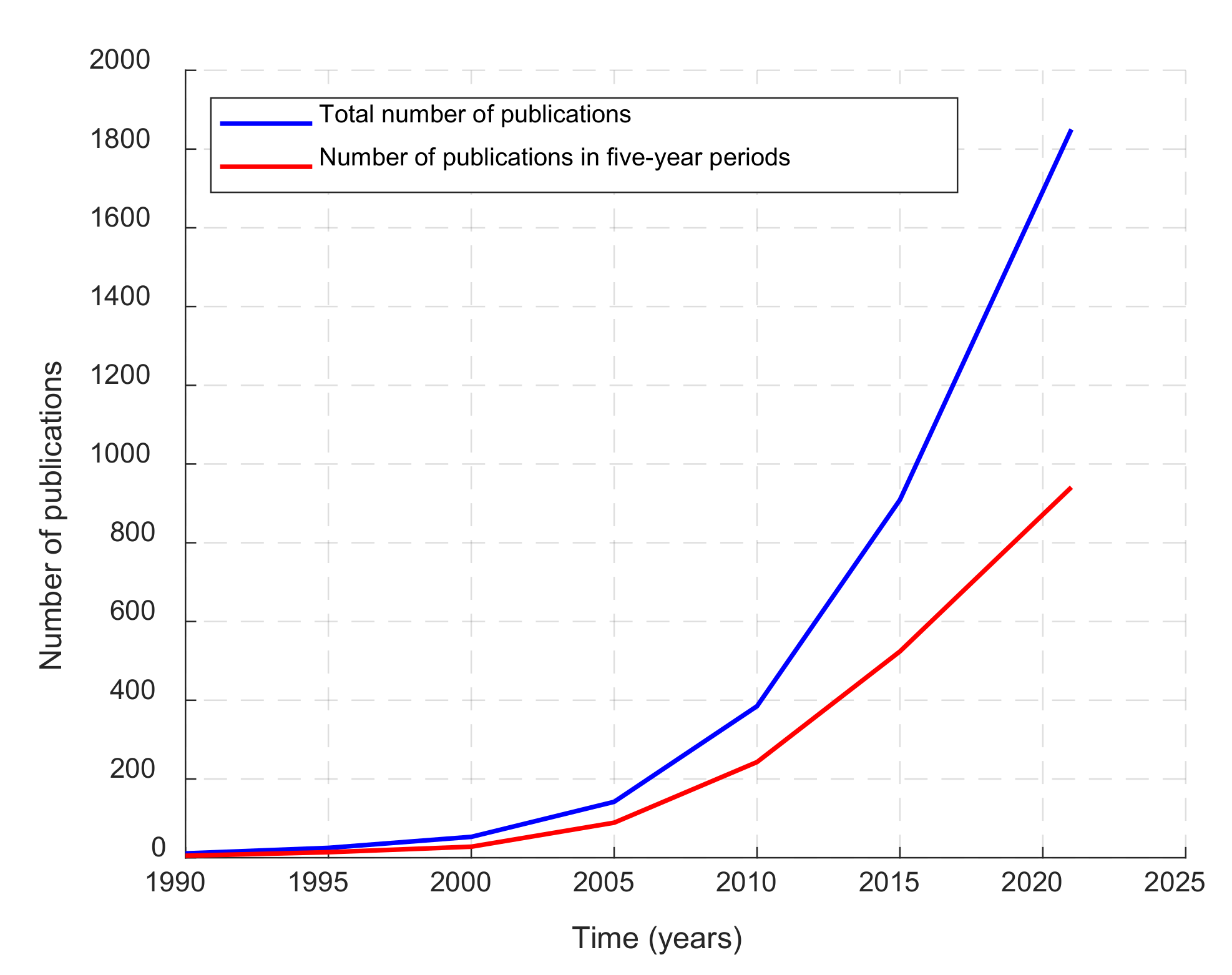
:1. Introduction
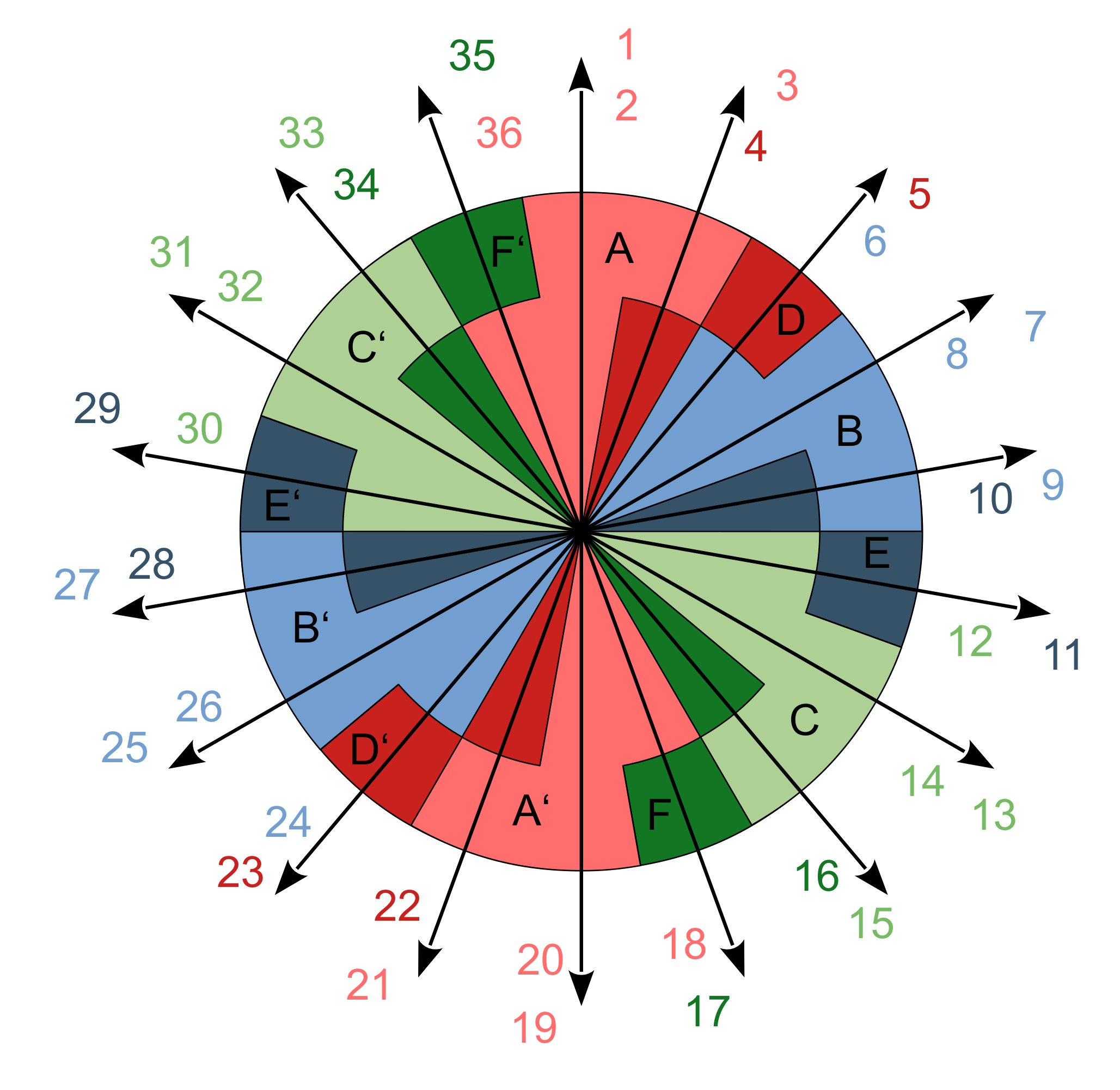
2. Winding Design of Multiphase Machines
2.1. Limits of the Winding Design
2.2. Design of Fractional-Slot Windings
Winding with an Even Number of Phases
2.3. Higher Order Harmonic Components Injection
3. Calculation of Equivalent Circuit Parameters
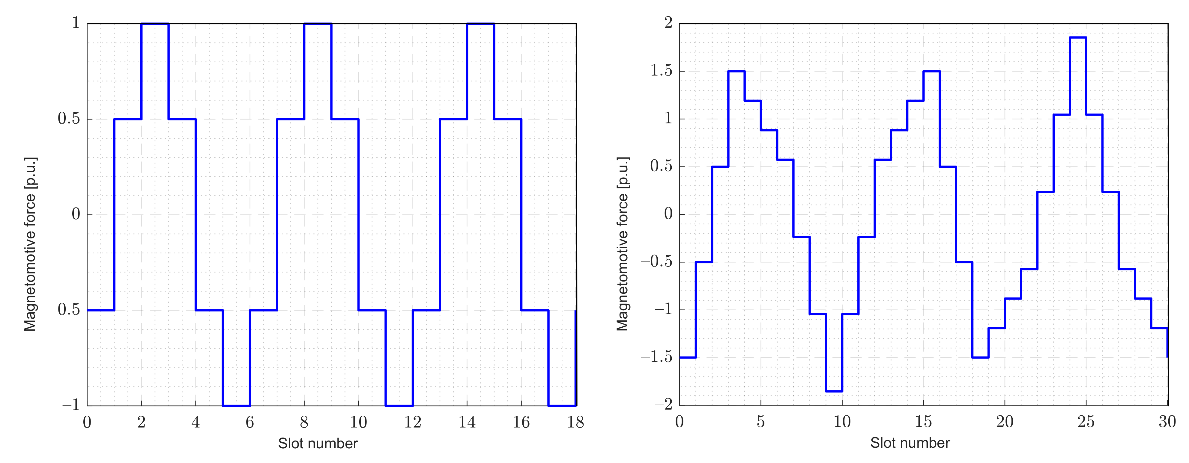
3.1. Slot Leakage Inductance
Higher Order Harmonic Component Injection
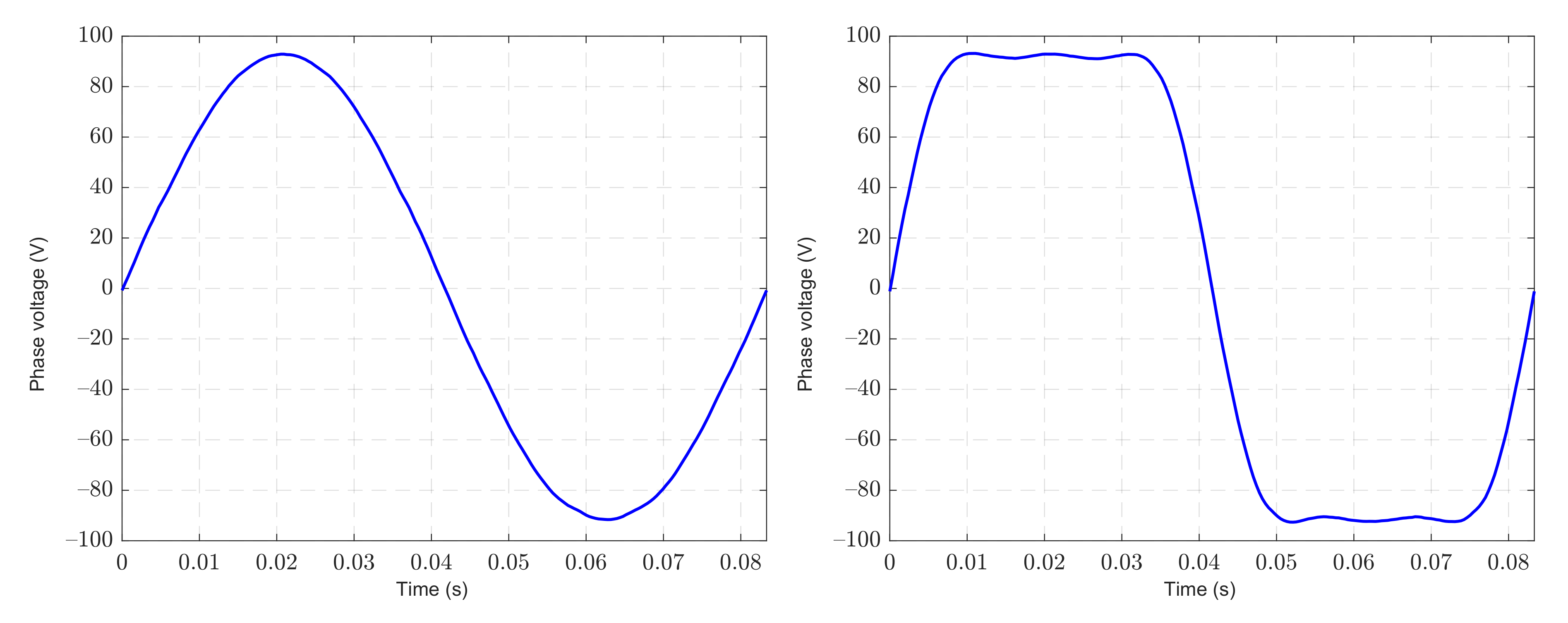
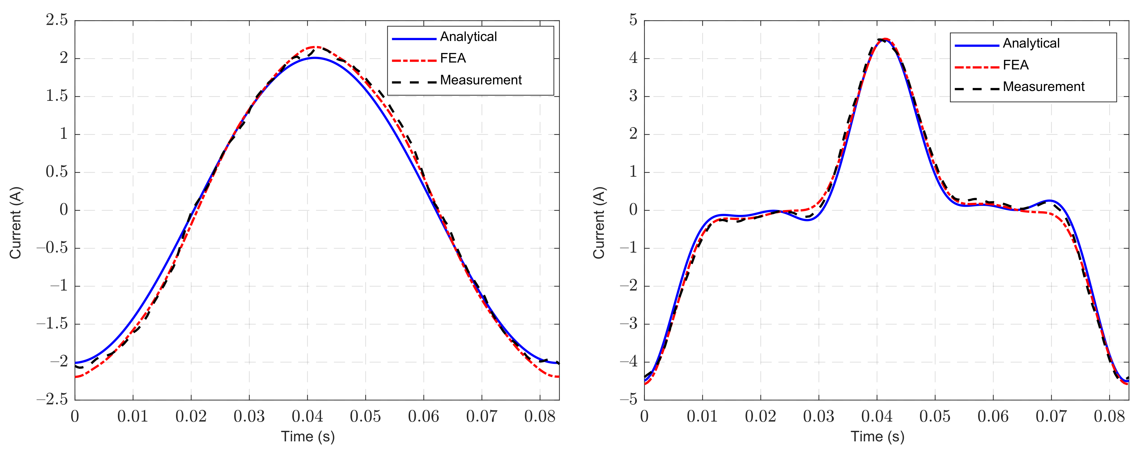
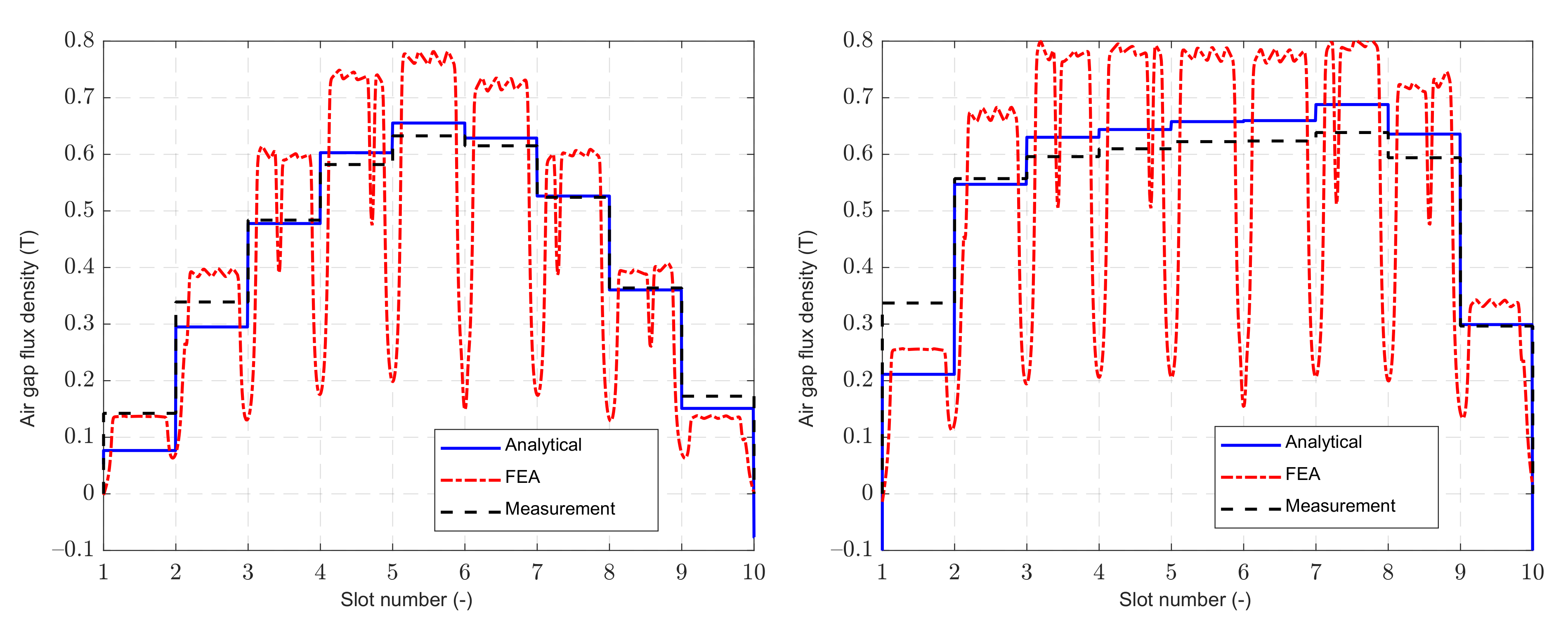
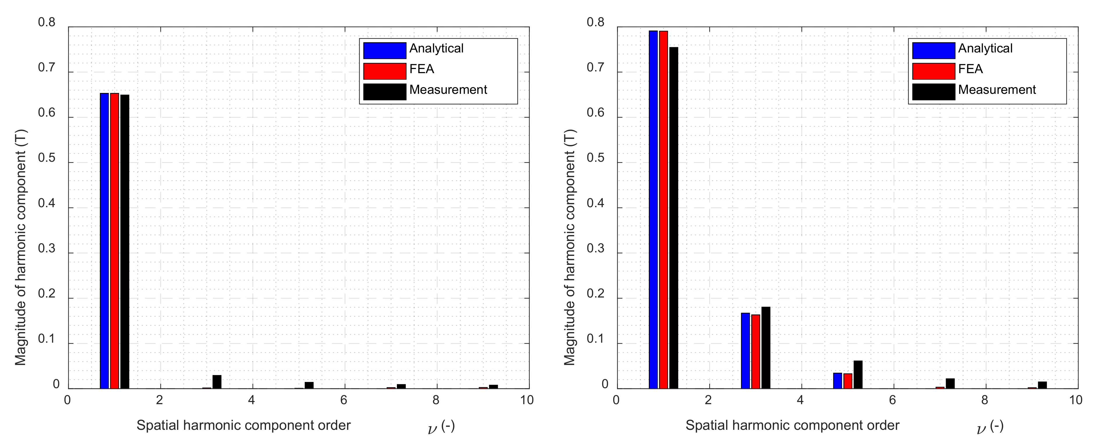
4. Example of a Nine-Phase Induction Machine
5. Discussion
Author Contributions
Funding
Institutional Review Board Statement
Informed Consent Statement
Data Availability Statement
Conflicts of Interest
References
- Salem, A.; Narimani, M. A Review on Multiphase Drives for Automotive Traction Applications. IEEE Trans. Transp. Electrif. 2019, 5, 1329–1348. [Google Scholar] [CrossRef]
- Aselsan HVSM-285 Nine-Phase Permanent Magnet Motor. Available online: https://www.aselsan.com.tr/HVSM285_Permanent_Magnet_Motor_For_HybridElectric_Vehicle_Applications_4348.pdf (accessed on 24 September 2021).
- Aselsan HVSM-287 Nine-Phase Permanent Magnet Motor. Available online: https://www.aselsan.com.tr/HVSM287_Permanent_Magnet_Synchronous_Motor_For_HybridElectric_Vehicle_Applications_3843.pdf (accessed on 24 September 2021).
- Levi, E. Multiphase Electric Machines for Variable-Speed Applications. IEEE Trans. Ind. Electron. 2008, 55, 1893–1909. [Google Scholar] [CrossRef]
- Duran, M.J.; Levi, E.; Barrero, F. Multiphase Electric Drives: Introduction; Wiley: Hoboken, NJ, USA, 2017; pp. 1–26. [Google Scholar] [CrossRef]
- Kindl, V.; Cermak, R.; Ferkova, Z.; Skala, B. Review of Time and Space Harmonics in Multi-Phase Induction Machine. Energies 2020, 13, 496. [Google Scholar] [CrossRef] [Green Version]
- Kong, W.; Qu, R.; Huang, J.; Kang, M. Air-Gap and Yoke Flux Density Optimization for Multiphase Induction Motor Based on Novel Harmonic Current Injection Method. In Proceedings of the 2016 XXII International Conference on Electrical Machines (ICEM 2016), Lausanne, Switzerland, 4–7 September 2016; pp. 100–106. [Google Scholar] [CrossRef]
- Abdel-Khalik, A.S.; Masoud, M.I.; Ahmed, S.; Massoud, A.M. Effect of Current Harmonic Injection on Constant Rotor Volume Multiphase Induction Machine Stators: A Comparative Study. IEEE Trans. Ind. Appl. 2012, 48, 2002–2013. [Google Scholar] [CrossRef]
- Wang, J.; Qu, R.; Zhou, L. Dual-Rotor Multiphase Permanent Magnet Machine with Harmonic Injection to Enhance Torque Density. IEEE Trans. Appl. Supercond. 2012, 22, 5202204. [Google Scholar] [CrossRef]
- De Gaetano, D.; Harikumaran, J.; Sala, G.; Degano, M.; Buticchi, G.; Gerada, C. On Torque Improvement by Current Harmonic Injection in Isotropic and Anisotropic Multi-Phase Machines. IEEE J. Emerg. Sel. Top. Ind. Electron. 2021, 2. (Early Access). [Google Scholar] [CrossRef]
- Abdel-Khalik, A.S.; Daoud, M.I.; Ahmed, S.; Elserougi, A.A.; Massoud, A.M. Parameter Identification of Five-Phase Induction Machines with Single Layer Windings. IEEE Trans. Ind. Electron. 2014, 61, 5139–5154. [Google Scholar] [CrossRef]
- Wang, P.; Zheng, P.; Sui, Y.; Wu, F.; Cheng, L.; Li, T. Design and Analytical Inductance Calculations of Five-Phase Fault-Tolerant Permanent-Magnet Machine. In Proceedings of the 2014 17th International Conference on Electrical Machines and Systems (ICEMS), Hangzhou, China, 22–25 October 2014; pp. 1639–1642. [Google Scholar] [CrossRef]
- Wang, D.; Wu, X.; Chen, J.; Guo, Y.; Cheng, S. A Distributed Magnetic Circuit Approach to Analysis of Multiphase Induction Machines with Nonsinusoidal Supply. IEEE Trans. Energy Convers. 2015, 30, 522–532. [Google Scholar] [CrossRef]
- Akay, A.; Lefley, P. Torque Ripple Reduction Method in a Multiphase PM Machine for No-Fault and Open-Circuit Fault-Tolerant Conditions. Energies 2021, 14, 2615. [Google Scholar] [CrossRef]
- Spas, S.; Kowarschik, S.; Laumer, J.; Wiesinger, M.; Hackmann, W. Five-Phase IPMSM: Torque Density Improvement by Third Harmonic Injection. In Proceedings of the 020 International Symposium on Power Electronics, Electrical Drives, Automation and Motion (SPEEDAM), Sorrento, Italy, 24–26 June 2020; pp. 779–786. [Google Scholar] [CrossRef]
- Riveros, J.A.; Yepes, A.G.; Barrero, F.; Doval-Gandoy, J.; Bogado, B.; Lopez, O.; Jones, M.; Levi, E. Parameter Identification of Multiphase Induction Machines with Distributed Windingspart 2: Time-Domain Techniques. IEEE Trans. Energy Convers. 2012, 27, 1067–1077. [Google Scholar] [CrossRef]
- Caruso, M.; Di Tommaso, A.O.; Marignetti, F.; Miceli, R. A General Investigation on the Differential Leakage Factor for Symmetrical and Asymmetrical Multiphase Winding Design. Energies 2020, 13, 5414. [Google Scholar] [CrossRef]
- Heller, B.; Hamata, V. Harmonic Field Effects in Induction Machines; Elsevier: Amsterdam, The Netherlands, 1977; p. 330. ISBN 044499856X. [Google Scholar]
- Levi, E.; Bojoi, R.; Profumo, F.; Toliyat, H.A.; Williamson, S. Multiphase Induction Motor Drives—A Technology Status Review. IET Electr. Power Appl. 2007, 1, 489–516. [Google Scholar] [CrossRef] [Green Version]
- Grandi, G.; Sanjeevikumar, P.; Casadei, D. Preliminary Hardware Implementation of a Six-Phase Quad-Inverter Induction Motor Drive. In Proceedings of the 2011 14th European Conference on Power Electronics and Applications, Birmingham, UK, 30 August–1 September 2011; pp. 1–9. [Google Scholar]
- Godwin, G.L. Dynamoelectric Machines for Multiples of Three Phases with Unbalanced Fractional-Slot Windings. U.S. Patent No. US4409507A, 11 October 1983. [Google Scholar]
- Khutoretsky, G.M.; Vorontsov, A.I.; Drozdova, L.A.; Yanik, B.S. Six-Phase Winding of Electric Machine Stator. U.S. Patent No. US4132914A, 2 January 1979. [Google Scholar]
- Hamilton, D.C.; Fleming, J.W. Dual, Three Phase, Inverter-Driven Motor. U.S. Patent No. US4220881A, 2 September 1980. [Google Scholar]
- Sui, Y.; Zheng, P.; Fan, Y.; Zhao, J. Research on the Vector Control Strategy of Five-Phase Permanent-Magnet Synchronous Machine Based on Third-Harmonic Current Injection. In Proceedings of the 2017 IEEE International Electric Machines and Drives Conference (IEMDC), Miami, FL, USA, 21–24 May 2017. [Google Scholar] [CrossRef]
- Pyrhonen, J.; Jokinen, T.; Hrabovcova, V. Design of Rotating Electrical Machines, 2nd ed.; John Wiley & Sons Ltd: Chichester, UK, 2013; p. 612. ISBN 978-1-118-58157-5. [Google Scholar]
- Vaske, P.; Riggert, J.H. Streuung umlaufender Maschinen (Leakage of rotating machines). In Elektrische Maschninen und Umformer, Teil 2. Berechnung Elektrischer Maschinen (Electrical Machines and Convertors, Part 2: Calculations of Electric Machinery), 7th ed.; B.G. Teubner: Stuttgart, Germany, 1967; pp. 50–58. [Google Scholar]
- Müller, G.; Vogt, K.; Ponick, B. Streuung (Leakage). In Berechnung Elektrischer Maschinen (Calculations of Electric Machinery); Wiley-Vch: Weihein, Germany, 2007; pp. 295–343. ISBN 978-3527405251. [Google Scholar]
- Boldea, I.; Nasar, S.A. Leakage inductances and resistances. In Induction Machine Handbook; CRC Press: Boca Raton, FL, USA, 2002; pp. 133–158. ISBN 0-8493-004-5. [Google Scholar]
- Laksar, J. Improved Calculation of the Slot Leakage Inductance of Different Slot Shapes. Electr. Eng. 2020, 102, 1129–1139. [Google Scholar] [CrossRef]
- Madariaga, C.; Jara, W.; Tapia, J.A.; Pyrhönen, J.; Lindh, P.; Riedemann, J.A. Closed-Form Solution for the Slot Leakage Inductance of Tooth-Coil-Winding Permanent Magnet Machines. IEEE Trans. Energy Convers. 2019, 34, 1572–1580. [Google Scholar] [CrossRef]
- Liwschitz-Garik, M.; Whipple, C. Electric Machinery, Vol. 2: A–C Machines; Van Nostrand Company, Inc.: New York, NY, USA, 1946. [Google Scholar]
- Cordovil, P.; Chabu, I.E. Analytical Calculation of Slot Leakage Inductance in Multiphase Electrical Machines. In Proceedings of the 2016 22th International Conference on Electrical Machines (ICEM), Lausanne, Switzerland, 4–7 September 2016; pp. 1352–1358. [Google Scholar] [CrossRef]
- Kalaj, P.; Cermak, R.; Frank, Z.; Kindl, V.; Komrska, T.; Laksar, J.; Peroutka, Z. Measurement of the Effects of Higher Harmonic Injection on Nine-Phase Induction Motor. In Proceedings of the IECON 2020 The 46th Annual Conference of the IEEE Industrial Electronics Society, Singapore, 18–21 October 2020; pp. 4851–4856. [Google Scholar] [CrossRef]


| Three-Phase | Multiphase | Advantages of Multiphase Machines | Disadvantages of Multiphase Machines | |
|---|---|---|---|---|
| Torque ripple frequency | 6f1 | 2mf1 | Lower vibrations | Increases the number of slots with the same number of slots per pole and phase |
| Order of the lowest space MMF harmonics caused by stator winding | Five and seven | 2m ± 1 | ||
| Winding distribution factor | Multiphase machines have a higher winding distribution factor than three-phase machines with the same number of slots per pole and phase in addition to the same relative coil pitch | More effective utilization of stator winding | ||
| Power per phase | P/3 | P/m | Lower demand on power components | Higher number of power components |
| Number of different winding connections | Two (star and delta) | >2 (depends on number of phases) | Greater connection variability and possibility to increase phase voltages | Each winding connection acts different with higher harmonics |
| Harmonic injection | Only with a non-rotating component | Possible with higher time harmonics | Increases/decreases peak amplitude/RMS | Possible increase in iron core losses |
| Changing the number of pole pairs | Only with Dahlander winding | Possible with higher time harmonics | Possibility to change number of pole pairs without winding switch-over | Increase in vibration and noise due to the lower numberof slots per pole and phase |
| Continued operation after an open-phase fault | No | Yes | ||
| Number of Phases, m | k | Relative Coil Pitch, β | Correction Factor, kc |
|---|---|---|---|
| 3 | 1 | ||
| 5 | 1 | ||
| 2 | |||
| 6 | 1 | ||
| 2 | |||
| 7 | 1 | ||
| 2 | |||
| 3 | |||
| Nine and more | - |
| Parameter | Value |
|---|---|
| Number of pole pairs | 2 |
| Number of phases | 9 |
| Rated power (kW) | 15 |
| Rated phase voltage (V) | 380 |
| Rated current (A) | 5.85 |
| Rated power factor (-) | 0.82 |
| Rated efficiency (-) | 0.91 |
| Rated frequency (Hz) | 50 |
| Rated speed | 1480 |
| Number of stator slots | 36 |
| Time Harmonic Component Order, μ (-) | |||
|---|---|---|---|
| 1 | 3 | 5 | |
| Angular frequency, ω (rad·s−1) | 75.4 | 226.2 | 377.0 |
| Main inductance, L (H) | 0.598 | 0.0664 | 0.0239 |
| Differential leakage factor, τdiff (%) | 1.02 | 9.66 | 29.8 |
| Differential leakage inductance, Ldiff (H) | 0.00611 | 0.00632 | 0.00712 |
| Slot leakage inductance, Lσs (H) | 0.00568 | 6.31·10−4 | 2.27·10−4 |
| Total stator inductance, Ls (H) | 0.610 | 0.0735 | 0.0313 |
| Stator reactance, Xs (Ω) | 45.98 | 16.62 | 11.79 |
| Single Harmonic | Higher Order Harmonic Injection | ||||
|---|---|---|---|---|---|
| Time harmonic component order μ (-) | 1 | 1 | 3 | 5 | |
| Time harmonic component, μ (-) | 1 | 1 | 3 | 5 | |
| Voltage, Um (V) | 92.5 | 111.8 | 25.6 | 6.28 | |
| Stator reactance, Xs (Ω) | 45.98 | 45.98 | 16.62 | 11.79 | |
| Stator resistance, Rs (Ω) | 1.36 | ||||
| Stator impedance, Zs (Ω) | 46.00 | 46.00 | 16.68 | 11.87 | |
| Phase shift, φ (°) | 88.3 | 88.3 | 85.3 | 83.4 | |
| Current, I (A) | Analytical | 2.01 | 2.43 | 1.54 | 0.53 |
| FEA | 2.14 | 2.63 | 1.44 | 0.46 | |
| Measurement | 2.12 | 2.63 | 1.473 | 0.45 | |
Publisher’s Note: MDPI stays neutral with regard to jurisdictional claims in published maps and institutional affiliations. |
© 2021 by the authors. Licensee MDPI, Basel, Switzerland. This article is an open access article distributed under the terms and conditions of the Creative Commons Attribution (CC BY) license (https://creativecommons.org/licenses/by/4.0/).
Share and Cite
Laksar, J.; Cermak, R.; Hruska, K. Challenges in the Electromagnetic Design of Multiphase Machines: Winding and Equivalent Circuit Parameters. Energies 2021, 14, 7335. https://doi.org/10.3390/en14217335
Laksar J, Cermak R, Hruska K. Challenges in the Electromagnetic Design of Multiphase Machines: Winding and Equivalent Circuit Parameters. Energies. 2021; 14(21):7335. https://doi.org/10.3390/en14217335
Chicago/Turabian StyleLaksar, Jan, Radek Cermak, and Karel Hruska. 2021. "Challenges in the Electromagnetic Design of Multiphase Machines: Winding and Equivalent Circuit Parameters" Energies 14, no. 21: 7335. https://doi.org/10.3390/en14217335
APA StyleLaksar, J., Cermak, R., & Hruska, K. (2021). Challenges in the Electromagnetic Design of Multiphase Machines: Winding and Equivalent Circuit Parameters. Energies, 14(21), 7335. https://doi.org/10.3390/en14217335