Article

An Analytical Modelling of Demand for Driving Torque of a Wheelchair with Electromechanical Drive

1
Faculty of Mechanical Engineering, Institute of Machine Design, Poznan University of Technology, 60-965 Poznań, Poland
2
Faculty of Architecture, Institute of Architecture and Physical Planning, Poznan University of Technology, 60-965 Poznań, Poland
*
Author to whom correspondence should be addressed.
Energies 2021, 14(21), 7315; https://doi.org/10.3390/en14217315
Submission received: 6 October 2021 / Revised: 28 October 2021 / Accepted: 1 November 2021 / Published: 4 November 2021
(This article belongs to the Special Issue Research on the Optimal Selection of Electromechanical Drives)

Abstract

:
This study aimed at analysing the influence of the position of the centre of gravity variability and the movement velocity on the demand for a torque and work time coverage of a wheelchair with an electromechanical drive. The variable parameter in the study was the configuration of the wheelchair, namely changes in the position of the batteries which changed the weight distribution. An analytical model describing the demand for torque was used in the analysis. The set of equations was introduced into the numerical calculation software. Simulations were carried out which allowed it to analyse selected parameters of the wheelchair dynamics. An increase in the torque demand was observed due to the increase in the mass of the system from 427.7 N to 533.1 N, ranging from 6.1% to 31.6% at the simulated velocity v7 = 4.2 m/s. The increase in the demand for torque due to the increase in velocity of the wheelchair from v2 = 1.05 m/s to v7 = 4.2 m/s ranged from 25.9% to 31.6% compared to the reference velocity v1 = 0.525 m/s. The centre of gravity of the wheelchair structure localization has a non-linear impact on the analysed values. At the same time, it was not possible to define its nature—this issue remains open and requires further research.

1. Introduction

Devices supporting the mobility of the disabled and infirm increase their independence [1] and psychological comfort [2], bringing great benefits to the whole society [3,4]. One of the oldest and most commonly used means of supporting the mobility of disabled people are wheelchairs. Wheelchair’s structures are dynamically developed in many directions, e.g., in order to increase the range of overcoming terrain obstacles (thresholds [5], stairs [6,7,8], elevations [9], ditches characterized by large differences in height [10]), both weight and dimensions reduction [11], frame reinforcements [12], technologies supporting propulsion [13], systems enabling the transmission of driving force from hands to wheels of a wheelchair with various degrees of dysfunction [14], structural improvements increasing the safety of movement [15,16], systems facilitating manual driving of the wheelchair, e.g., gears [8,17]. The group that has been most developed in recent years consists of electric wheelchairs with the possibility of supporting the manual propulsion [18,19,20]. This technique is beneficial for the health of people with disabilities, as it provides them with physical activity in the range of their abilities resulting from the driving force demand [21]. The disadvantages of structures equipped with an electric drive that facilitates drive are increased resistance to motion [22], greater weight [23], problems with learning to control such a wheelchair [24,25,26,27], and difficulties arising in transporting such wheelchair by another means of transportation [28]. However, the benefits resulting from the possibility of independent movement, along with the possibility of physical exertion by a disabled person during such activities, are much more important than the above-mentioned disadvantages. The authors believe that the technology that uses electric drives to assist the movement of disabled people will continue to develop dynamically [29]. The developed structures will be faced with ever higher requirements concerning the limitation of the energy consumption of the driving process realized by electric drives [30,31], and the reduction of both manufacturing and operation of such wheelchairs [32,33,34]. Moreover, the mechanisms and electrical systems used in them should also be characterized by the lowest possible energy consumption [35]. An electric assisted wheelchair is, in principle, a parallel hybrid (manual-electric) drive [36]. For this reason, when designing such devices, the mechanical parameters [37] should be taken into account, such as the location of the centre of gravity [38], the weight of the structure [39], the efficiency of mechanisms [40], as well as electrical parameters such as, for example, battery capacity [39], power and efficiency of drive units [41], etc. This paper deals with the analysis of the impact of changing the position of the centre of gravity resulting from the distribution of the wheelchair’s elements (primarily the battery packs) on the torque demand and energy consumption during movement. In a wheelchair, different types of wheels are used on the front and rear axles, which have different resistance to motion characteristics also at the same time depending on the load distribution [40]. The location of the batteries in wheelchairs is also important for accessibility during the charging process [42].
The aim of the presented research work was to determine the influence of mass and spatial arrangement of the elements of the electric wheelchair drive system on the demand for drive torque and on the range of its movement. The range of the wheelchairs movement was determined in the context of the time that the electric system can work for the adopted weight variant and the arrangement of the batteries during the movement at a given velocity. The set of such data can be used to more efficiently select electromechanical drives and the elements included in such systems.
The results of the work presented in this paper are a continuation of author’s research on wheelchairs. Previously, the influence of changes in the position of the human body while driving a wheelchair on the position of the centre of gravity of the entire system was analysed [38,43]. It can therefore be stated that this work is rather focused on analysing changes occurring in the system as a result of its configuration, apart from the human factor.

2. Materials and Methods

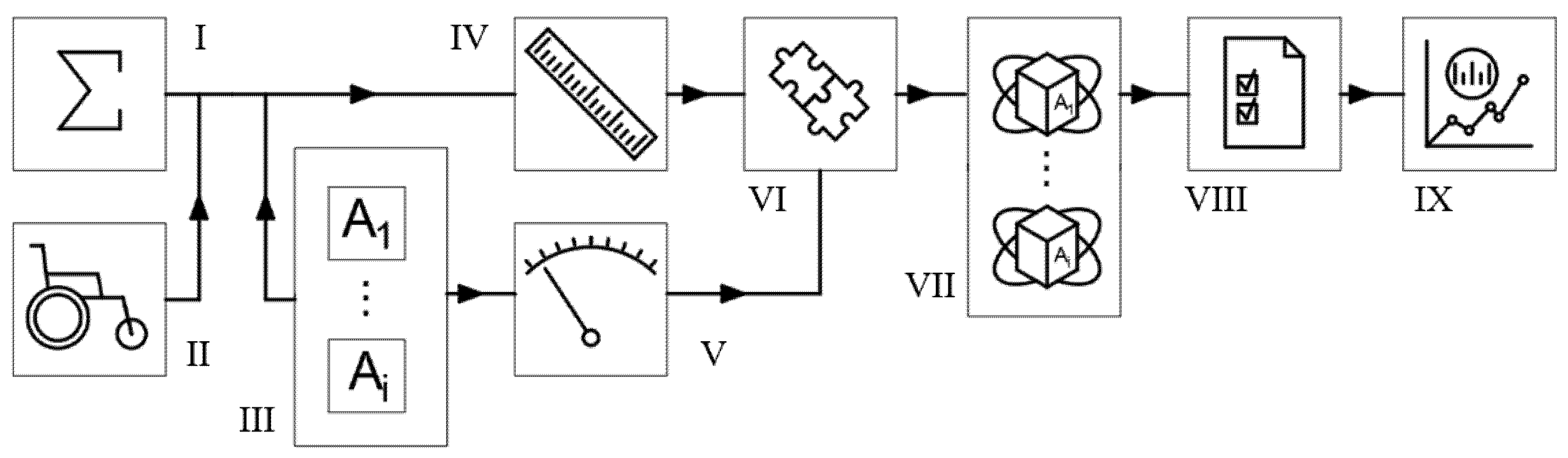
2.1. Research Work Conception

The entirety of work carried out can be presented as a diagram which shows a sequence in which its successive stages were performed (Figure 1). First, a system of equations describing the forces acting on a wheelchair was produced. The basis for the development of this system is the sum of the forces acting on the wheelchair, projected on the direction of movement. A wheelchair with a hybrid electric-manual drive was used for the tests and analysis. It is a certain development of the concept of an electric wheelchair, but in principle it has a mode of operation that allows it to be classified into this group. The above-mentioned steps became the basis for carrying out measurements. First, the geometry of the tested system was measured, as it was crucial to obtain a number of parameters necessary for the simulation. Then, variants of variable parameters in the simulation were defined and adopted. They were associated with different masses and the arrangement of batteries supplying the drives and control system of the wheelchair. As a result, it was possible to perform a number of measurements of the variable values—that is, the masses and the location of the centre of gravity of the entire system. A series of collected data was introduced into the numerical computing environment. As a result, simulation tests were carried out for all adopted variants. The determined values were then related to the characteristics of the drive system and power supply, which allowed for the development of a set of results. This provided the basis for compiling and comparing the effects of the calculations performed for all the adopted variants.
A detailed description of the methodology for the implementation of the indicated stages of research work has been described in the following subchapters of the “Methods” section. For the sake of clarity, the order indicated in this subsection was followed. A complete list of all notations and physical quantities used in this paper can be found in Appendix A in Table A1.
The novelty of the presented research process results from the use of the mathematical model used classically to describe the movement of a motor vehicle to describe the movement of a wheelchair. It required introducing changes resulting from differences between these systems. In the case of a wheelchair, the location of the centre of gravity is of particular importance, which results from both the human factor (analysed in the work [38] as well as the configuration of the wheelchair itself. In the presented study, this matter was analysed on the example of an electric wheelchair with a different arrangement of the batteries which altered both the weight of the system as well as its concentration in relation to the wheel’s axles. The high significance of the C O G position in the case of a wheelchair results from a much lower weight ratio of a wheelchair and a human being compared to a motor vehicle.
Limitations of the research result mainly from the elements used in the adopted method. The results of the measurements refer to specific variants of the wheelchair resulting from its dimensions, the choice of the type of battery and electric drives and its placement. Although it should be expected that the nature of the observed changes will be similar, on the basis of the presented data it is impossible to directly relate them to, e.g., a wheelchair equipped with a different type of electric drive. In turn, the advantage of this approach is that the developed mathematical model is so general that its implementation in different cases remains possible after minor changes or modifications are made. In its present form, the model describes the movement of a wheelchair in a straight line.

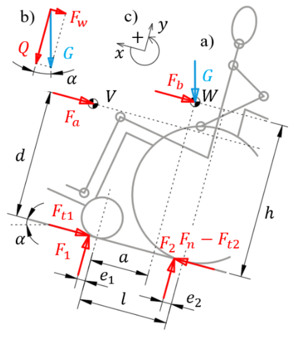
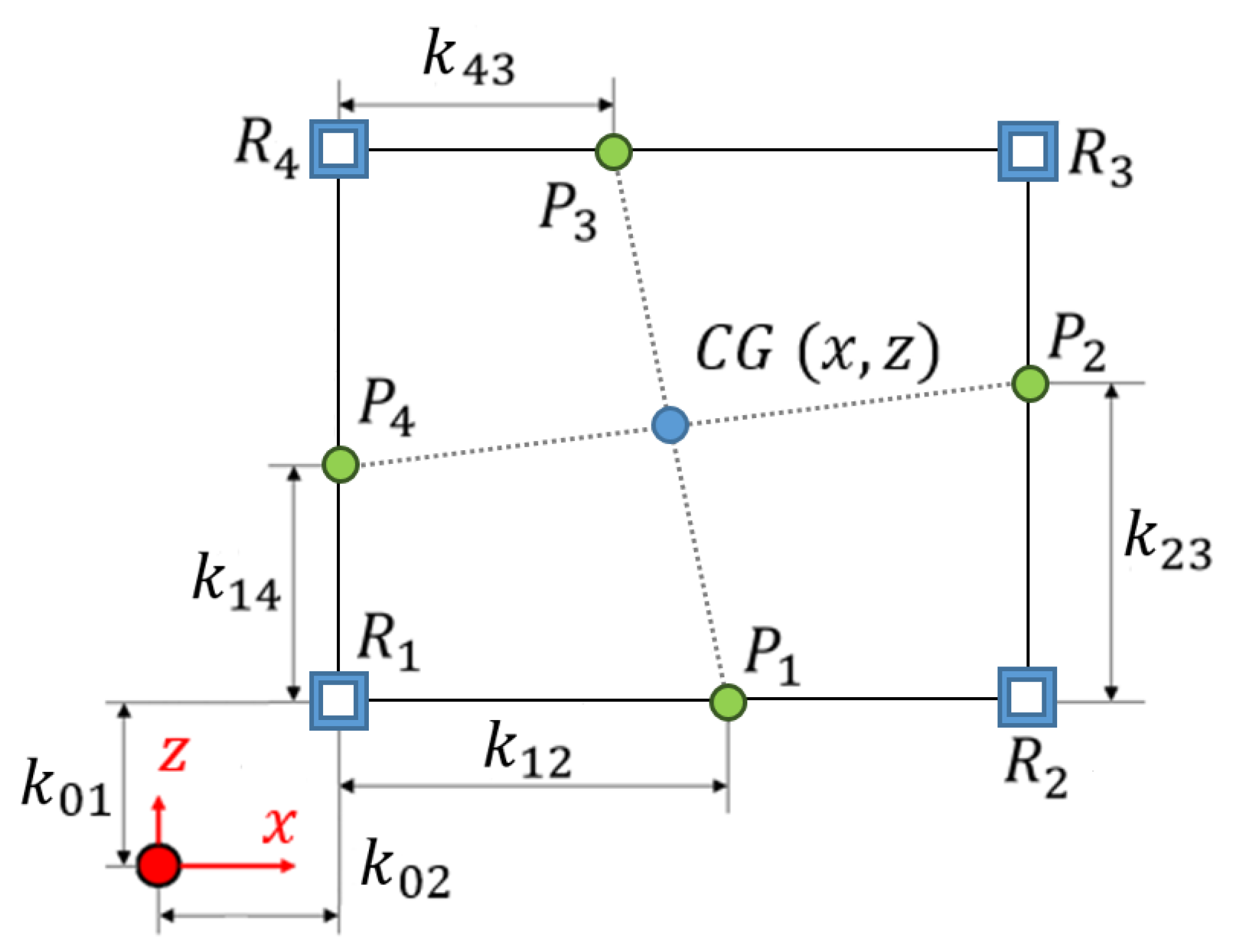
2.2. Analytical Basics of Modelling

The distribution of forces acting on the wheelchair along with the user, projected into the direction of movement, is shown in Figure 2. The presented mathematical model is based on the description of the sum of forces acting on the wheelchair during its movement on a hard, flat surface at a given angle α . From a mechanical point of view, the system is considered to be flat, therefore the forces are applied at the points of operation on a two-dimensional plane. The inertia force of the system F b is applied in the centre of gravity of the system at point W , as is the gravity force (weight of the system) G . The aerodynamic drag force F a was applied in the centre of the system height (half of the height) at point V . The frictional force of the smaller wheel F t 1 was applied at the moment arm of rolling resistance for smaller wheel e 1 in the opposite direction to the movement of the wheelchair. The frictional force of the larger wheel F t 2 was summed (with the opposite sign to counteract the movement) with the propulsion force F n and applied to the moment of the arm of rolling resistance for larger wheel e 2 . In the same places, the ground reaction forces F 1 and F 2 were applied, which load the individual wheel axles. The sum written in this way allows to determine the value of the necessary driving force F n , from which the demand for driving torque is then calculated. Ultimately, individual forces are described in more detail into physical quantities that define their value.
The case analysis was based on the assumption of symmetry of the system. This is, of course, a certain approximation of reality, because neither the weight of the wheelchair nor the weight of the user has to be symmetrically distributed with respect to the left and right pair of wheels. Symmetry can be disturbed by many factors, including small pressure differences in the larger wheels of a wheelchair. With that being said, the ideal symmetry assumption is acceptable because the worst-case criterion is usually used when calculating and selecting a drive. Knowing the demand for driving torque in an ideal (symmetrical) case, it is easy to determine the demand for driving torque in the event of uneven loading of either side of the wheelchair. The advantage arising of such an assumption is, however, the possibility of considering only half of the wheelchair, which basically comes down to a coplanar system (i.e., one that is contained on a two-dimensional plane)—which significantly simplifies the calculations. As a result, the values of the demand for torque are determined for one of the two larger wheels of the wheelchair.
The sum of the projections of forces on the wheelchair travel axis can be written as:
F n F t F w F a F b ± J k 1 r d 1 r t 1 x ¨ t ± J k 2 r d 2 r t 2 x ¨ t = 0 ,
where F t is to be considered total friction force while F w –longitudinal force. The following physical quantities are: J k 1 and J k 2 are the moments of inertia with respect to the axis of rotation for respectively smaller and larger wheels. The expression x ¨ t is linear acceleration. The other values depend on the geometry of the system are defined as r d 1 and r d 2 are the dynamic radiuses of the wheels for respectively smaller and larger ones; r t 1 and r t 2 are consistently the rolling radiuses of the smaller and larger wheels.
This expression, after describing the component forces in detail and being multiplied by the dynamic radius of the larger wheel, allows to obtain the dependence on the torque T n necessary to drive the wheelchair under given conditions:
T n = ( F 1 f 1 + F 2 f 2 + G   s i n   α ) r d 2 + 0.047 A p C x r d 2 r t 2 2 φ ˙ 2 t G g r d 2 r t 2 + r d 2 r t 2 r d 1 r t 1 J k 1 + J k 2 φ ¨ t ,
where f 1 is rolling resistance coefficient of the smaller wheel, f 2 is rolling resistance coefficient of the larger wheel, G is weight of the system, α is inclination angle, A p is the surface area of the front face of the system, C x is a dimensionless factor of aerodynamic drag, φ ˙ t is angular velocity, and φ ¨ t is angular acceleration, g is acceleration due to gravity. In Equation (2) the value F 1 represents a load on the smaller wheel axle and F 2 —on the larger wheel axle which can be described as:
F 1 = 0.047 d A C x r t 2 φ ˙ 2 t     G h g r t 2 φ ¨ t     G h s i n α   +   G l     a   e 2 c o s α e 1   +   l     e 2 , F 2 = 0.047 d A C x r t 2 φ ˙ 2 t   ±   G h g r t 2 φ ¨ t   +   G h s i n α     G e 1   +   a c o s α e 1   +   l     e 2 ,
where: d is vertical position of system’s centre of height, h is vertical position system’s centre of gravity, a is the distance from the axle of the smaller wheel to the centre of gravity, and l is the distance between the axles of the wheelchair’s wheels. Detailed derivation of the model described by Equations (1)–(3) can be found in the previous publication of the authors [44].
The demand for the mechanical power P M that must be met by the wheelchair drive is described by Equation (4):
P M = T n φ ˙ t = 9550 1 · T n n ,
where T n is the driving torque determined according to Equation (2) based on previous assumptions, n is rotational speed in (rpm) of the wheelchair’s larger wheel. If into Equation (4) the value of T n will be substituted in (Nm) and the value of n in (rpm), then the resulting unit for P M will be (kW), which is favourable for further calculations.
Assuming that the drive will be utilizing a DC motor, the electric power will be defined by the formula (5):
P E = U · I ,
where U is the voltage and I stands for electric current. Both power values P M and P E are related to each other by the total efficiency of the system. The total efficiency η of a system is the product of the efficiency of its elements and mechanisms. A number of such elements can be indicated in the system, but the specification of all individual efficiency values is extremely difficult, therefore the most important ones were adopted in further considerations, and the others were simplified according to Equation (6):
η = η e m · η b 2 · η r ,
where η e m is the efficiency of electric motor, η b is the efficiency of bearings and η r is the efficiency of the rest of the system (losses resulting from, among others, electrical resistance, heat losses and power consumption of the control system). Formulas (4) and (5) must be multiplied by time in order to receive units as kilowatt-hour, yielding:
P M t M = P E t E η ,
where t M is work time coverage (work time of the mechanical part), and in turn t E is work time of the electric system determined on the basis of the knowledge of the ampere-hours parameter of the batteries. Substituting (4) and (5) to (7) and transforming those equations allows for obtaining the relationship (8) which relates the quantity that defines the battery capacity, the operating parameters of electric motors, efficiency, but also the demand for driving torque:
t M = U I t E · η · 9550 T n n .
The value of T n in turn is dependent, as Equation (2) shows, on a number of parameters resulting from the geometry and weight of the wheelchair. In this study, the variables (i.e., the analysed parameters) were the mass of the system and its distribution, and thus also the resulting displacement of the centre of gravity of the wheelchair itself.
Substituting successive values of mass m and the location of the center of gravity (defined by parameter a ), and for various cases, it is possible to determine the operating time of the system (work time coverage) t M , which results not only from the capacity of the batteries used, but also from their location in relation to the plane of the wheelchair movement.

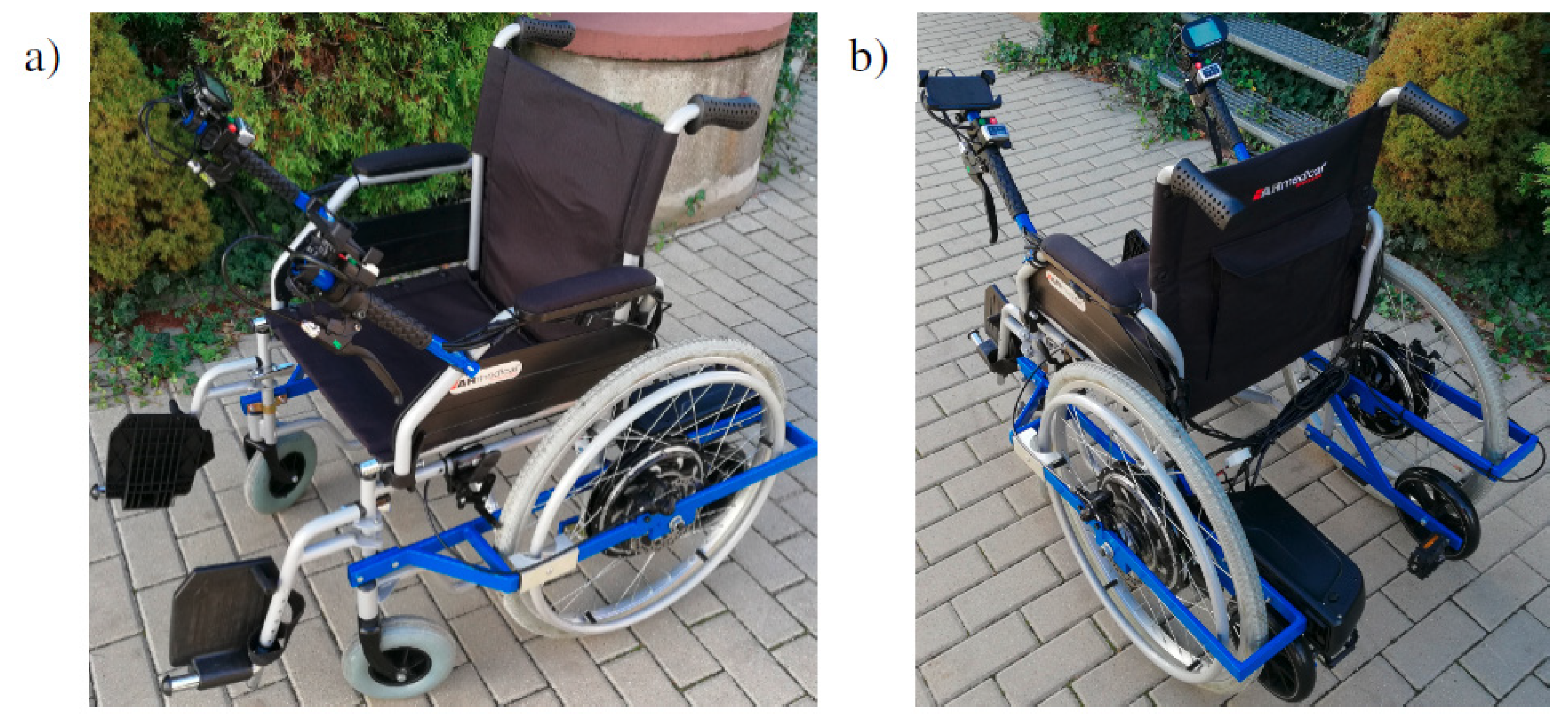
2.3. Hybrid Electric-Manual Wheelchair

A wheelchair with a hybrid electric-manual drive was used in the research. It was created by equipping the classic Breezy 90 wheelchair (Sunrise Medial S. L.) with the MagicPie 5 electric drive units by Goldenmotor. The invention has a control system that allows it to work in various modes—it can use electric drives to completely propel the system, but also only to support the manual drive carried out by the user. The system is equipped with control levers, manual brakes and an LCD screen so as to simplify its operation as much as possible from the user’s point of view. The whole is powered by a Li-ION battery, which has been permanently attached to the frame at the rear of the wheelchair. The developed device is shown in Figure 3a,b. It was created on the basis of the PAT 2102 patent; a detailed description of this wheelchair can be found in [45]. The developed drive system of the presented device constitutes an electro-mechanical drive in its entirety.

2.4. Test and Simulation Variants

In order to carry out calculations and simulations, nine variants of the wheelchair configuration were adopted A 1 A 9 . They were mainly created by different mass distributions, in the form of batteries within an electric wheelchair. The diagram of the geometry of the adopted variants is shown in Figure 4. The drawings are made to scale, the dimensions of symmetrically placed elements are not repeated, and the defined dimensions are not given again, unless they have changed. The dimensions were drawn with respect to a fixed point, which was always in the same place and was the reference for the coordinate system (the origin of the coordinate system), which was marked in blue. Referring to the coordinate system introduced in Figure 2, the axis in the direction of movement is the x axis and the second axis in the plane of movement is the z axis, since the y axis remains upward (see Figure 2a). Introduced axis designations of the Cartesian coordinate system are consistently preserved throughout the text. The first variant A 1 is a classic Breezy 90 wheelchair, while the next variant A 2 is a modified wheelchair, equipped with MagicPie 5 electric drives. The variant A 3 is a modified wheelchair, with a battery in the rear part, on the left-hand side from the user’s perspective. This is the case of the actual system described in Section 2.3. The variant A 4 it has a battery located centrally under the seat. A 5 and A 6 have two symmetrically placed batteries, the first of which is located at the rear of the wheelchair, and the second under the seat. The variants form A 7 to A 9 are modifications of A 5 created by adding weights simulating batteries successively by adding one in the front part of the wheelchair, adding two (one after the other) behind the seat and finally adding two symmetrically placed on the sides of the stroller under the seat. The variants A 1 and A 2 were adopted for the purpose of comparison and experimental determination of the mass of electric drives and batteries. The small dimensional deviations in relation to the commercially available Breezy 90 wheelchair result from modifications made to its structure in order to attach the cooperating elements constituting the invention.
Before the test, the larger (pneumatic) wheels of the wheelchair were inflated to the nominal pressure value of 3 ± 0.1 bar suggested by the manufacturer. The configurations from A 2 to A 9 used the same wheelchair; the position and amount of additional mass were changed without changing its position and other parameters, including tire pressure. Therefore, the pressure in the pneumatic wheels did not affect the position of the centre of gravity in the test conducted on dynamometer (detailed dynamometer description is presented in the next section).

2.5. Constant Parameters of the Simulation

The values of the geometrical and physical quantities of the system were either adopted on the basis of the literature or measured directly, as it is shown in Table 1. The geometry was determined during measurements made on a wheelchair immobilized on a test stand (dynamometer).

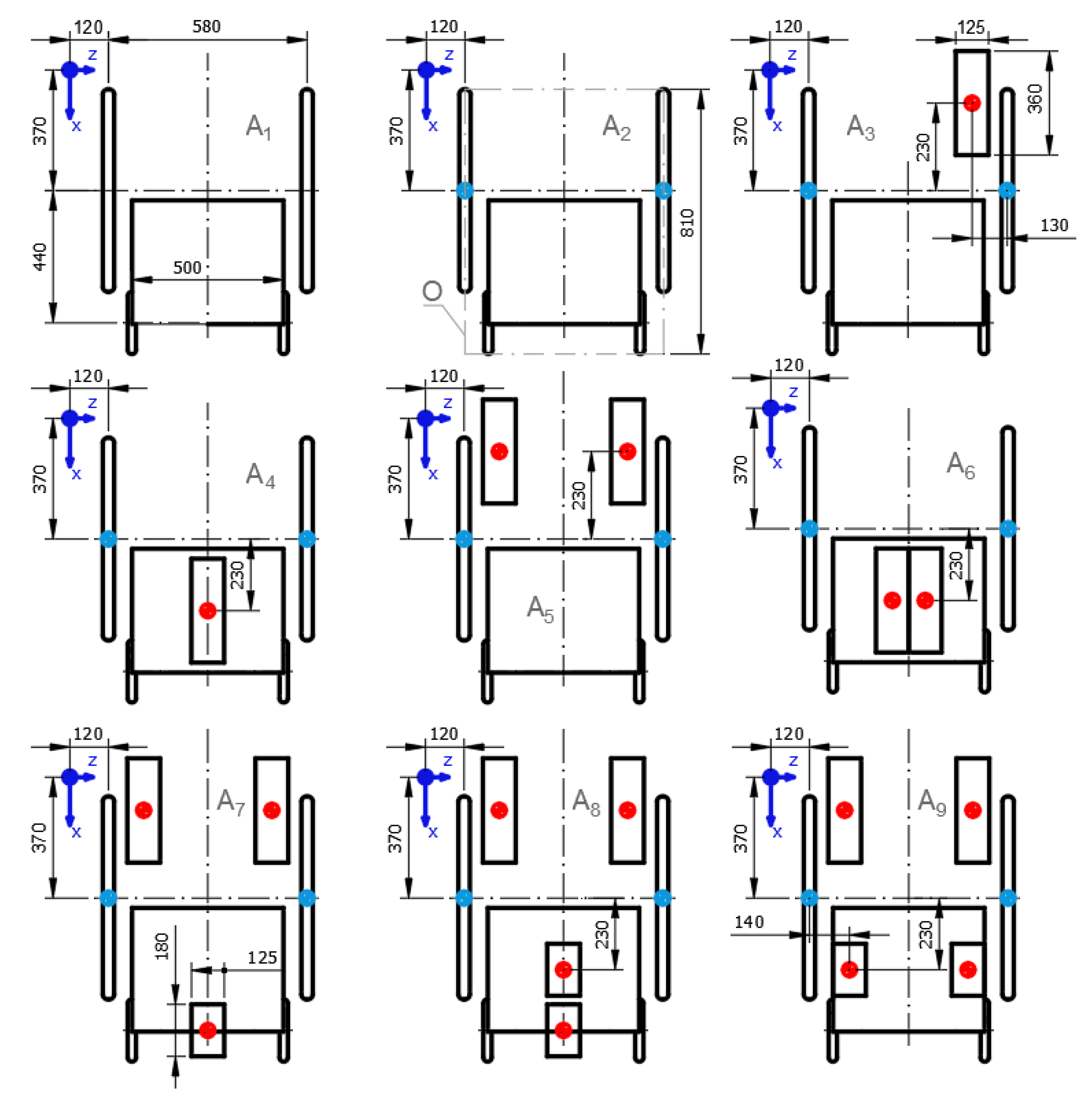
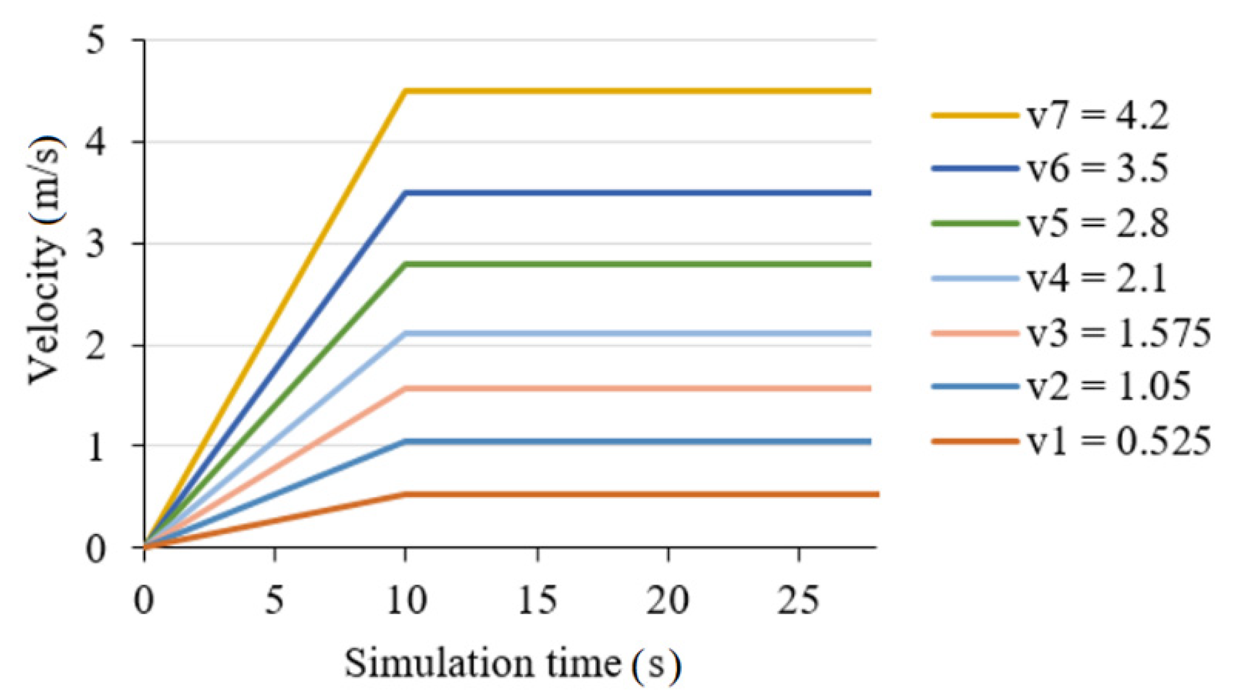
2.6. Variable Parameters of the Simulation

Conducting the simulation required the determination of the mass and the location of the centre of gravity of a wheelchair that was not modified and equipped with electric drives and a control system with batteries. For this purpose, a wheelchair dynamometer was used. It is equipped with a measurement system that uses the HBM PMX data acquisition system. Mass measurements are carried out thanks to the Z6FC6 100 kg transducers, also by HBM. The measurement consists of registering the weight of the weighing pan with the wheelchair in four support places R 1 R 4 , and its general idea is presented in Figure 5. The knowledge of systems dimensions allows for determining the location of centre of gravity ( C G ) at the intersection of lines drawn form points P 1 P 4 . Characteristic dimensions k 12 ,   k 14 ,   k 23 ,   k 43 that define the points P 1 P 4 are determined using statics equations for individual planes of the system. A detailed description of the principle of determining the centre of gravity according to this method can be found in [43]. The values of dimensions k 01 and k 02 define the location of strain gauges in relation to the adopted coordinate system (as shown on Figure 4).
As a result of the measurements, a cloud of 2500 points was obtained defining the location of the C G of the wheelchair for a given variant with respect to the origin of the x coordinate system as shown in Figure 5. The masses of the wheelchair in individual configurations were also recorded A 1 A 9 . For the estimator of the searched values (the location of C G on x axis and the mass of the system for a given variant) the arithmetic mean was adopted, and the estimator error was the standard deviation of the arithmetic mean.
Determining the distance from the axle of the smaller wheel to the centre of gravity a for individual cases equals to the difference in dimensions given in Figure 4 for the variant A 1 , that being the value of 810 mm and the result of the position of C G measurement on x axis.

2.7. Numerical Simulation

The developed system of Equations (2), (3) and (8) was introduced to the MatLab Simulink numerical computing environment (MAthWorkks, v.R2015a). The simulations were conducted with a time step of Δ t = 0.005 s, assuming a known velocity profile. For the sake of simplicity, it has been assumed that the wheelchair will accelerate to the set velocity with a constant acceleration for the duration of 10 s, (so as not to cause too high dynamic loads). After reaching a set value, it will be maintained until the end of the simulation, as shown in Figure 6.

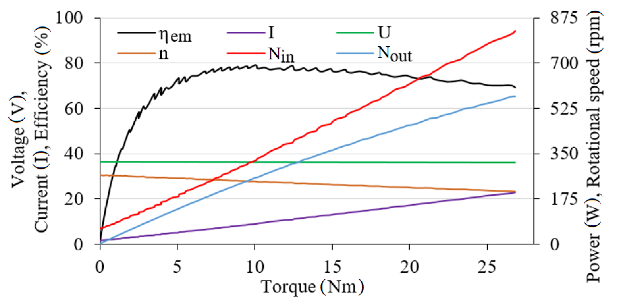
2.8. Characteristics of the Electric Drive

The parameters related to the motors driving the wheelchair and electric energy batteries were read directly from the data provided by the manufacturer of the applied solutions. The graph in Figure 7 shows the performance of the Golden Motor MagicPie 5 system.
For the calculated values of the torque demand T n of the wheelchair, depending on the simulation variant, appropriate values of the supply current I , rotational speed n , and efficiency η e m were assumed for further calculations. The battery [54] used in the solution had the nominal voltage of U = 36 V. Its capacity equals to 13 Ah and it corresponds to the term: I · t E in Equation (8). Weights simulating auxiliary batteries had a similar mass (determined in detail in the further part of the study). The proportional dependence of capacity to battery mass was assumed, therefore the use of auxiliary batteries assumes a proportional increase in value of I · t E . It is worth noting here that the relationship between the mass of the battery and its capacity in general is not necessarily linear and depends on a number of factors, including its type. However, due to the slight differences in masses shown later, the assumption of a linear relationship does not introduce a significant error in the calculations. The introduction of the results obtained from Equations (2) and (3) and the values read from the characteristics of the used electric drive allows for determination the working time of the mechanical system t M using Equation (8). It essentially is the work time coverage, which directly translates into the vehicle’s travel range (in the context of the maximum possible distance achievable under given conditions for a given velocity).
In order to perform numerical calculations, the efficiency curve of the electric motor was approximated by (9) according to the dependency:
η e m = a 1 + a 2 T n 1 + a 3 T n + a 4 T n 2 ,
with a 1 a 4 being the parameters of this equation that were calculated as values: a 1 = −3.84·10−1, a 2 = 4.95·10, a 3 = 4.49·10−1 and a 4 = 8.48·10−3. For the adopted values, the correlation coefficient was 0.99.

3. Results and Discussion

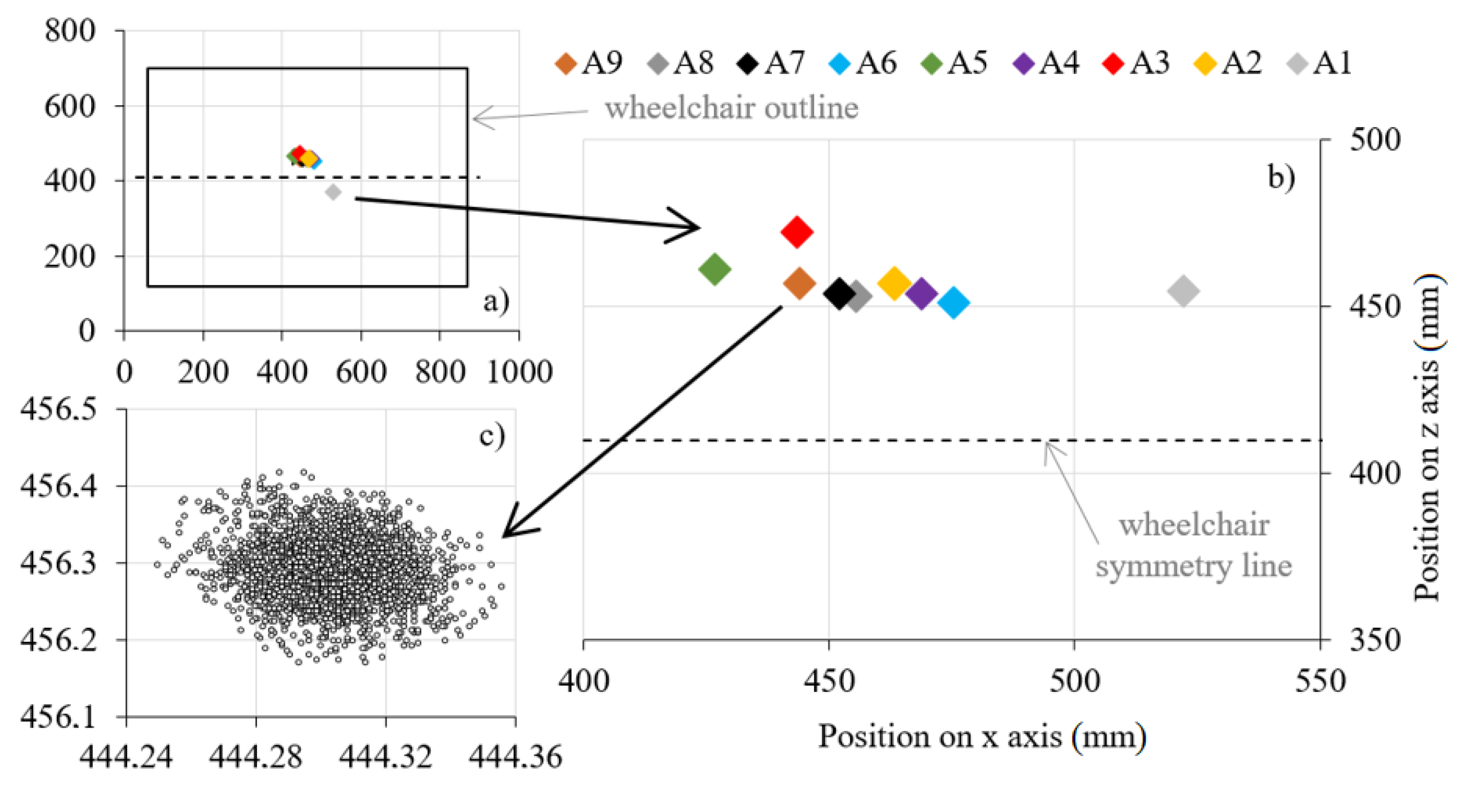
3.1. Centre of Gravity and Mass Measurements Results

The measurement results of the location of C G for individual variants are presented in Figure 8, the specific values are collected in Table 2. It also presents the determined values of the weight G and distance from the axle of the smaller wheel to the centre of gravity a for individual cases. They were adopted for further calculations. The difference in the masses of selected variants makes it possible to easily determine the masses of the system components. Thus, the weight of the wheelchair itself is m 0 = 17.55 kg (for traditional and standard wheelchair, such mass should be considered typical, it is consistent with the results of other researchers [55,56]), the mass of the drives with accessories and mounting is m 1 = 26.0 kg, the mass of a single battery is m 2 = 2.66 kg (this is typical mass for batteries in such a range of solutions, other researchers report it in the range between 0.7 kg and 7 kg [57,58]), and the averaged mass of a single weight is m 3 = 2.72 kg. Therefore, considering the earlier assumption of a linear mass to capacity ratio of the battery, auxiliary batteries capacity equals to I · t E = 13.3 Ah (compared to nominal batteries capacity I · t E = 13 Ah).
The analysis of the results shows that the C G of the wheelchair is not ideally located in its geometric axis of symmetry. This may be due to a number of factors. The manufacturing accuracy of the individual elements of the system is finite, so obtaining perfectly equal masses and symmetry of their mounting is not achievable [59]. In any case, this parameter does not affect the simulation results because the position of the C G on the z axis is not analyzed in this paper. At this point however, it is worth noting that, in general, the position of the C G on the z axis affects the load on the individual axles of wheelchair [60] and may be an important parameter in some cases—in particular during curvilinear motion [61,62].

3.2. Work Time Coverage and Torque Demand

The values obtained as a result of the simulation are presented in Table 3. The calculation results related to the determination of the work time coverage value as a function of the wheelchair’s velocity and the total system weight are shown in Figure 9a. As it results from the analysis of the presented graph, with the increase in velocity, the possible working time of the system decreases because the electric drive requires greater quantities of electricity to achieve and maintain it. The changes caused by the weight alteration are of the opposite nature, and also occur with much larger increments. This seemingly illogical effect is the result of the fact that the mass added to the system by additional batteries results in an increase in their capacity. Apparently, the increase in capacity progresses more rapidly than the increase in torque demand caused by the extra weight. This parameter however has an upper limit resulting mainly from the available space that the batteries can occupy. It is also indirectly related to the strength (in terms of load capacity) of the wheelchair frame structure.
The effect of weight on the tested parameters is approximately linear, while the effect of velocity is a quadratic function, as can be seen more clearly in Figure 9b. On the other hand, the position of the centre of gravity on the x axis, represented by the parameter a , remains in a much more complicated relation to the demand for driving torque, as shown by the plane shown in Figure 10. The value of the parameter a seems to have a non-linear effect on the demand for driving torque [63]. The location of the centre of gravity depends on the mass, but also on the geometry of the entire system [64], and this relationship in the general case remains a complicated function resulting from the location of the centre of mass in three dimensions. The non-linear relationship between the tested parameters and the value of the parameter a is shown in Figure 11a,b. Analytical determination of the equations determining the exact relationship between the position of the centre of gravity and the distribution of mass remains theoretically possible. However, performing such analysis for a system with so many elements would be inefficient as it would be extremely time-consuming process. In practice, the position of the C G of complex systems (such as vehicles) is determined experimentally, for example, by means of strain gauges [65,66], similar to the methodology described in Section 2.6, or the measurement of the moment of inertia [67]. An unambiguous and direct determination of impact nature of the parameter a on the studied quantities is problematic and needs more study.
Next, a comparison of the position of the system’s additional mass in relation to the geometrical centre of the wheelchair was analysed. Thus, two groups of configurations were determined. The “Front” configuration including variants: A 4 , A 6 , A 8 that have the greater part of the battery weight shifted towards the front of the wheelchair (towards increasing values on the x axis). On the other hand, configuration variants “Rear”, being: A 3 , A 5 , and A 9 were determined as the opposite. A similar arrangement was analysed for motor vehicles in [68]. The additional mass was concentrated in the direction of decreasing quantities on the axis according to the adopted coordinate system, therefore they had a greater value of the parameter a because this quantity is measured from the axis of rotation of the smaller wheel. These configurations properly arranged in pairs (as shown in Figure 12) have similar weights; the slight difference is due to measurement inaccuracy. The analysis of this diagram shows that the shift of the C G towards the rear wheels increases the torque demand. Most likely, this is due to the uneven load on the wheelchair wheels’ axes. For increasing values of the a parameter, the load on the larger wheel axle increases. Moving the C G towards the axis of the larger wheel causes an increase in the demand for torque, as it significantly increases the second part of Equation (2), which is F 2 f 2 · r d 2 . Placing the battery at the front part of the wheelchair results in a more even distribution of weight by adding load to the front axle, thus reducing the need for driving torque.
In order to show the scale of the changes in the value of torque demand and work time coverage, the proportions were arranged according to Equation (10):
x 1 x 0 x 0 · 100 % ,
where x 1 is the quantity after the change and x 0 is the quantity before the change (reference quantity). For the assumed relationship, increases will be positive, and decreases negative. For the analysis of the torque demand, the reference value was the value for a wheelchair with electric drives but without a battery ( A 2 variant for velocity of v 1 ), while for the analysis of work time coverage, the value for a wheelchair with one battery in the “Rear” position was adopted ( A 2 variant for velocity of v 1 ). The set of obtained results is presented in Figure 13 and Figure 14.
The analysis of the presented charts confirms the earlier observations. The increase in velocity and at the same time, the rise of the system weight along with its shift towards the larger wheels of the wheelchair increases the demand for drive torque. Simultaneously, adding auxiliary batteries to the system (although it increases the overall mass and affects the C G ), for selected ranges of variability of said parameters, results in an increase in work time coverage, effectively increasing the battery capacity. Conversely, an increase in the wheelchair velocity causes a decrease in the maximum capacity of the battery as it results in an increased demand for power. Part of the graph’s bars (on Figure 14) change sign, because in the relation to the A 2 variant, the addition of auxiliary batteries at a sufficiently low simulated wheelchair velocity results in a large increase in their total capacity. For those cases it results in an increase in work time coverage.

4. Conclusions

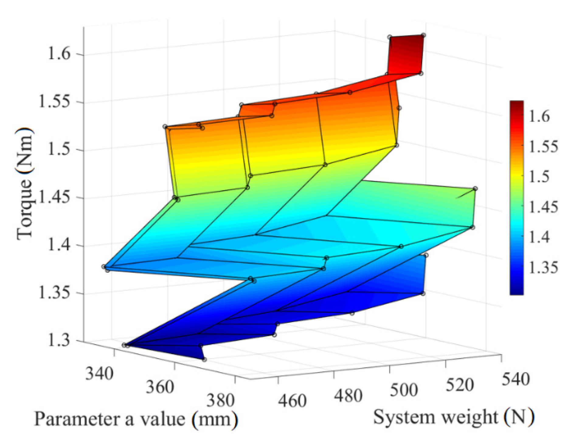
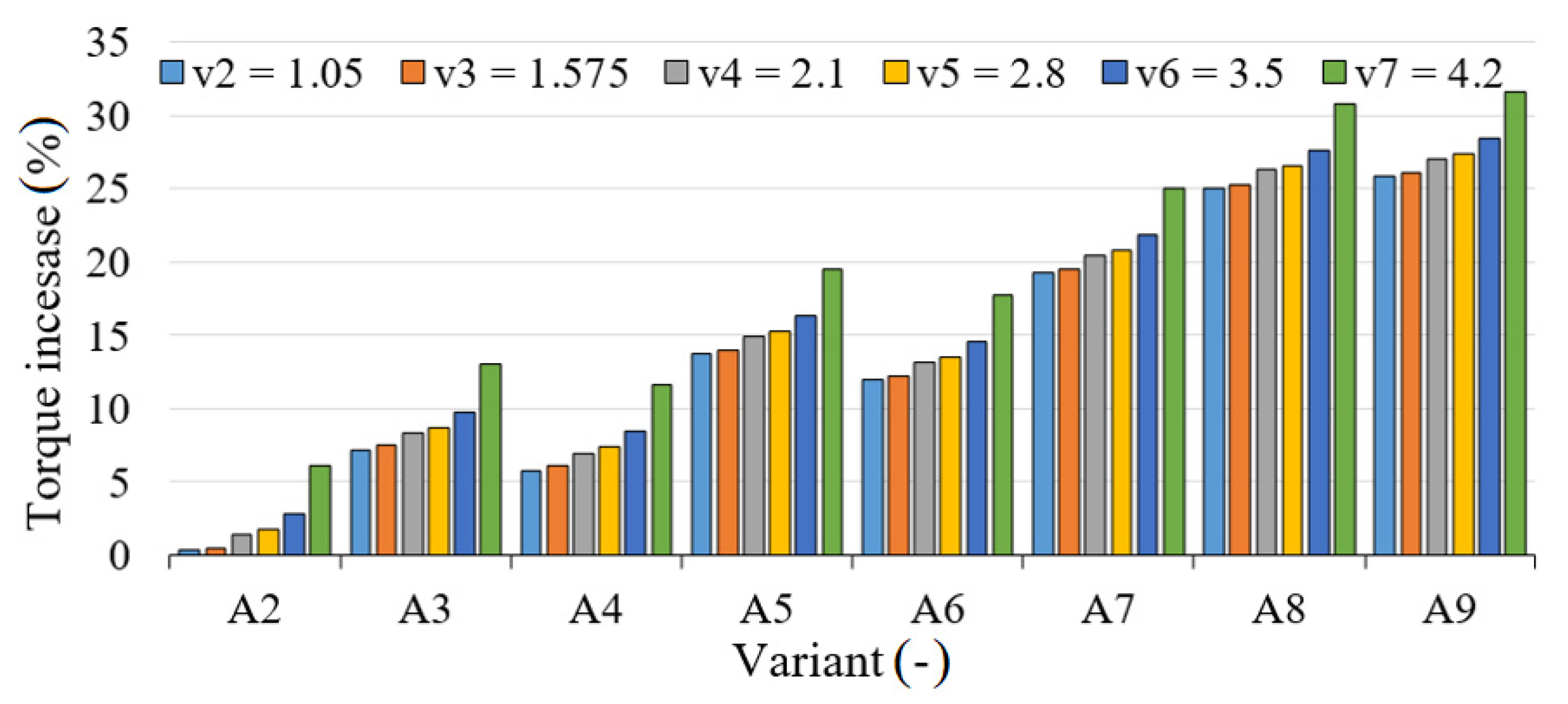
  • As the weight of the system increases, the demand for drive torque increases and work time coverage is increasing, with an approximately linear trend;
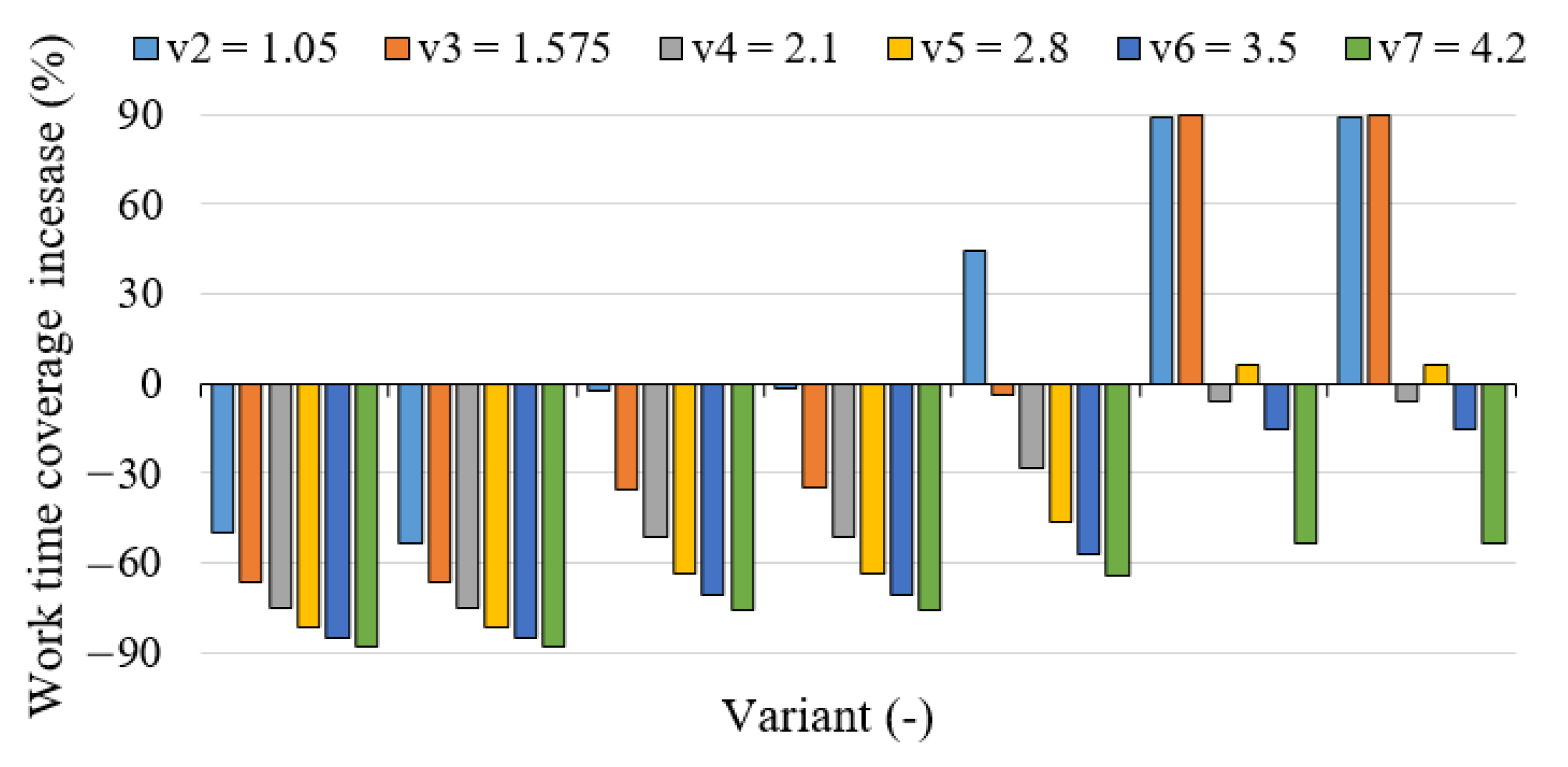
  • As the weight of the system increases, so does the work time coverage despite the increase in driving torque demand;
  • The increase in the simulated velocity causes changes in the demand for driving torque and work time coverage, the change being approximately a square function;
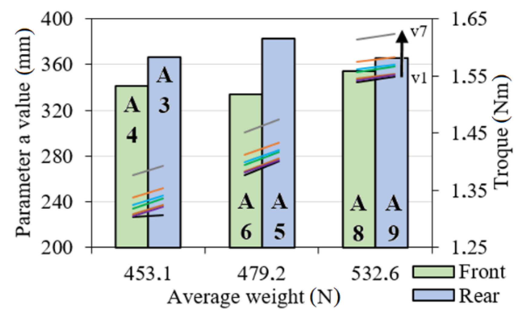
  • The set of recorded data does not allow for an unambiguous and direct determination of impact nature of the parameter value a (distance from the axle of the smaller wheel to the center of gravity) on the torque demand and work time coverage. This issue remains open and requires further research;
  • The most advantageous case is one where the greatest possible mass of the battery is placed as close as possible to the front wheels of the wheelchair.

5. Patents

Patent at the Patent Office of the Republic of Poland: PL PAT 2102 (application number P.427855), Modification kit for a hybrid electric-manual wheelchair drive system (original title in Polish: Zestaw modyfikacyjny układu napędu do hybrydowego elektryczno-ręcznego do wózka inwalidzkiego), WIECZOREK Bartosz, WARGUŁA Łukasz, KUKLA Mateusz, 2021.
Patent application at the Patent Office of the Republic of Poland: P.424482, Simulation device for the wheelchair operating conditions and the measurement of dynamic parameters (original title in Polish: Urządzenie do symulacji warunków eksploatacji i pomiaru parametrów.

Author Contributions

Conceptualization, M.K., B.W. and Ł.W.; methodology, M.K., B.W. and Ł.W.; software, M.K.; validation, M.K., B.W. and Ł.W.; formal analysis, M.K.; investigation, M.K., B.W., Ł.W. J.G. and M.G.; resources, M.K., B.W., J.G.; data curation, M.K., B.W., Ł.W., J.G. and M.G.; writing—original draft preparation, M.K., Ł.W.; writing—review and editing, M.K., B.W., Ł.W., J.G. and M.G.; visualization, M.K., B.W., Ł.W., J.G. and M.G.; supervision, M.K.; project administration, M.K.; funding acquisition, M.K. All authors have read and agreed to the published version of the manuscript.

Funding

This research is a part of the project: “Innovative Drive Systems for Wheelchairs—Design, Prototype, Research, number: “Rzeczy są dla ludzi/0004/2020” financed by National Centre for Research and Development, https://www.gov.pl/web/ncbr (accessed on: 3 October 2021).

Institutional Review Board Statement

Not applicable.

Informed Consent Statement

Not applicable.

Data Availability Statement

Not applicable.

Conflicts of Interest

The authors declare no conflict of interest.

Appendix A

A complete list of all notations and physical quantities used in this paper can be found in Appendix A in Table A1.
Table A1. List of markings used in the paper.
Symbol Description
α Inclination angle
Δ t Time step of a simulation
φ ˙ t Angular velocity
φ ¨ t Angular acceleration
η Total efficiency
η e m Electric motor efficiency
η b Bearing efficiency
η r Efficiency of the rest of the system
a Distance from the axle of the smaller wheel to the centre of gravity
a 1 a 4 Equation parameters
A 1 A 9 Variants of wheelchair configuration
A p Surface area of the front face of the system
C x Dimensionless factor of aerodynamic drag
d Vertical position of system’s centre of height
e 1 Moment arm of rolling resistance for smaller wheel
e 2 Moment arm of rolling resistance for larger wheel
f 1 Rolling resistance coefficient of the smaller wheel
f 2 Rolling resistance coefficient of the larger wheel
F 1 Load on the smaller wheel axle
F 2 Load on the larger wheel axle
F a Aerodynamic drag force
F b Inertia force of the system
F n Propulsion force
F t Total friction force
F t 1 Frictional force of the smaller wheel
F t 2 Frictional force of the larger wheel
F w Longitudinal force
g Acceleration due to gravity
G Weight of the system
h Vertical position system’s centre of gravity
I Electric current
J k 1 Moment of inertia of the smaller wheel with respect to the axis of rotation
J k 2 Moment of inertia of the larger wheel with respect to the axis of rotation
k 12 , k 14 ,   k , k 43 , k 01 , k 02 Characteristic dimensions of the system for determining the position of the center of gravity
l The distance between the axles of the wheelchair’s wheels
m 0 Mass of the wheelchair
m 1 Mass of the drives with accessories and mounting elements
m 2 Mass of the battery
m 3 Average mass of the weight plate
n Rotational speed
O Wheelchair outline
P 1 P 4 Characteristic points of the system for determining the position of the centre of gravity
P E Electrical power
P M Mechanical power
r 1 Radius of the smaller wheel
r 2 Radius of the larger wheel
r d 1 Dynamic radius of the smaller wheel
r t 1 Rolling radius of the smaller wheel
r d 2 Dynamic radius of the larger wheel
r t 2 Rolling radius of the larger wheel.
R 1 R 4 Point of support
T n Propulsion torque
t E Work time of the electric system
t M Work time coverage (work time of the mechanical part)
U Voltage
v 1     v 7 Velocity variants
x ¨ t Linear acceleration

References

  1. Zhou, H.; Hou, K.-M.; Zuo, D.; Li, J. Intelligent Urban Public Transportation for Accessibility Dedicated to People with Disabilities. Sensors 2012, 12, 10678–10692. [Google Scholar] [CrossRef] [PubMed]
  2. Morales, Y.; Watanabe, A.; Ferreri, F.; Even, J.; Shinozawa, K.; Hagita, N. Passenger discomfort map for autonomous navigation in a robotic wheelchair. Robot. Auton. Syst. 2018, 103, 13–26. [Google Scholar] [CrossRef]
  3. Wong, M.C.S.; Yap, R.C.Y. Social Impact Investing for Marginalized Communities in Hong Kong: Cases and Issues. Sustainability 2019, 11, 2831. [Google Scholar] [CrossRef] [Green Version]
  4. Rousseau-Harrison, K.; Rochette, A.; Routhier, F.; Dessureault, D.; Thibault, F.; Côté, O. Impact of wheelchair acquisition on social participation. Disabil. Rehabil. Assist. Technol. 2009, 4, 344–352. [Google Scholar] [CrossRef]
  5. Szrek, J.; Muraszkowski, A. Synthesis of an Automatic Obstacle overcoming Control Module, dedicated for Manual Wheelchairs. Acta Polytech. Hung. 2018, 15, 45–57. [Google Scholar]
  6. Hinderer, M.; Friedrich, P.; Wolf, B. An autonomous stair-climbing wheelchair. Robot. Auton. Syst. 2017, 94, 219–225. [Google Scholar] [CrossRef]
  7. Sasaki, K.; Eguchi, Y.; Suzuki, K. Stair-climbing wheelchair with lever propulsion control of rotary legs. Adv. Robot. 2020, 34, 802–813. [Google Scholar] [CrossRef]
  8. Madanhire, I.; Gwizo, T.; Mbowa, C. Design Improvement of Off-road Rough Uneven Rural Terrain Wheelchair. In Proceedings of the 2nd European Conference on Industrial Engineering and Operations Management (IEOM), Paris, France, 26–27 July 2018; pp. 2613–2626. [Google Scholar]
  9. Wu, B.F.; Chen, Y.S.; Huang, C.W.; Chang, P.J. An uphill safety controller with deep learning-based ramp detection for intelligent wheelchairs. IEEE Access 2018, 6, 28356–28371. [Google Scholar] [CrossRef]
  10. Favey, C.; Farcy, R.; Donnez, J.; Villanueva, J.; Zogaghi, A. Development of a New Negative Obstacle Sensor for Augmented Electric Wheelchair. Sensors 2021, 21, 6341. [Google Scholar] [CrossRef]
  11. Nonaka, M.; Kashiwazaki, H.; Ura, S.; Nagamori, M.; Uchiyama, H.; Shionoya, A. Evaluation of Driving Performance of Two Types of Competitive Wheelchairs for Badminton Made of Two Different Metallic Materials. Proceedings 2020, 49, 161. [Google Scholar] [CrossRef]
  12. Zipfel, E.; Cooper, R.A.; Pearlman, J.; Cooper, R.; Mccartney, M. New design and development of a manual wheelchair for India. Disabil. Rehabil. 2007, 29, 949–962. [Google Scholar] [CrossRef]
  13. Shionoya, A.; Kenmotsu, Y. Development of new wheelchair for sports competition. Proceedings 2018, 2, 257. [Google Scholar] [CrossRef] [Green Version]
  14. Quaglia, G.; Bonisoli, E.; Cavallone, P. The Design of a New Manual Wheelchair for Sport. Machines 2019, 7, 31. [Google Scholar] [CrossRef] [Green Version]
  15. Rozendaal, L.A.; Veeger, H.E.J.; Van Der Woude, L.H.V. The push force pattern in manual wheelchair propulsion as a balance between cost and effect. J. Biomech. 2003, 36, 239–247. [Google Scholar] [CrossRef]
  16. Lee, J.; Jeong, W.; Han, J.; Kim, T.; Oh, S. Barrier-Free Wheelchair with a Mechanical Transmission. Appl. Sci. 2021, 11, 5280. [Google Scholar] [CrossRef]
  17. Gowran, R.J.; Clifford, A.; Gallagher, A.; McKee, J.; O’Regan, B.; McKay, E.A. Wheelchair and seating assistive technology provision: A gateway to freedom. Disabil. Rehabil. 2020, 8, 1–12. [Google Scholar] [CrossRef]
  18. Oh, S.; Hori, Y. Disturbance attenuation control for power-assist wheelchair operation on slopes. IEEE Trans. Control. Syst. Technol. 2013, 22, 828–837. [Google Scholar]
  19. Oh, S.; Kong, K.; Hori, Y. Operation state observation and condition recognition for the control of power-assisted wheelchair. Mechatronics 2014, 24, 1101–1111. [Google Scholar] [CrossRef]
  20. Wieczorek, B.; Warguła, Ł.; Rybarczyk, D. Impact of a Hybrid Assisted Wheelchair Propulsion System on Motion Kinematics during Climbing up a Slope. Appl. Sci. 2020, 10, 1025. [Google Scholar] [CrossRef] [Green Version]
  21. Conners, R.T.; Bates, L.C.; Lassalle, P.P.; Zieff, G.; Whitehead, P.N.; Stevens, S.; Killen, L.; Cochrum, R.; Rodebaugh, K.L.; Faghy, M.; et al. Current and Future Implications of COVID-19 among Youth Wheelchair Users: 24-Hour Activity Behavior. Children 2021, 8, 690. [Google Scholar] [CrossRef]
  22. Wargua, Ł.; Kukla, M.; Wieczorek, B. The impact of wheelchairs driving support systems on the rolling resistance coefficient. IOP Conf. Ser. Mater. Sci. Eng. 2020, 776, 012076. [Google Scholar] [CrossRef]
  23. Van der Woude, L.H.; De Groot, S.; Janssen, T.W. Manual wheelchairs: Research and innovation in rehabilitation, sports, daily life and health. Med. Eng. Phys. 2006, 28, 905–915. [Google Scholar] [CrossRef]
  24. Yang, Y.-S.; Koontz, A.M.; Hsiao, Y.-H.; Pan, C.-T.; Chang, J.-J. Assessment of Wheelchair Propulsion Performance in an Immersive Virtual Reality Simulator. Int. J. Environ. Res. Public Health 2021, 18, 8016. [Google Scholar] [CrossRef]
  25. Kloosterman, M.G.; Snoek, G.J.; Van der Woude, L.H.; Buurke, J.H.; Rietman, J.S. A systematic review on the pros and cons of using a pushrim-activated power-assisted wheelchair. Clin. Rehabil. 2013, 27, 299–313. [Google Scholar] [CrossRef]
  26. Guillon, B.; Van-Hecke, G.; Iddir, J.; Pellegrini, N.; Beghoul, N.; Vaugier, I.; Figère, M.; Pradon, D.; Lofaso, F. Evaluation of 3 pushrim-activated power-assisted wheelchairs in patients with spinal cord injury. Arch. Phys. Med. Rehabil. 2015, 96, 894–904. [Google Scholar] [CrossRef]
  27. Kloosterman, M.G.; Eising, H.; Schaake, L.; Buurke, J.H.; Rietman, J.S. Comparison of shoulder load during power-assisted and purely hand-rim wheelchair propulsion. Clin. Biomech. 2012, 27, 428–435. [Google Scholar] [CrossRef]
  28. Antonelli, M.G.; Alleva, S.; Beomonte Zobel, P.; Durante, F.; Raparelli, T. Powered off-road wheelchair for the transportation of tetraplegics along mountain trails. Disabil. Rehabil. Assist. Technol. 2019, 14, 172–181. [Google Scholar] [CrossRef]
  29. Alqahtani, S.; Joseph, J.; Dicianno, B.; Layton, N.A.; Toro, M.L.; Ferretti, E.; Tuakli-Wosornu, Y.A.; Chhabra, H.; Neyedli, H.; Lopes, C.R.; et al. Stakeholder perspectives on research and development priorities for mobility assistive-technology: A literature review. Disabil. Rehabil. Assist. Technol. 2021, 16, 362–376. [Google Scholar] [CrossRef]
  30. Hussain, S.; Ali, M.U.; Nengroo, S.H.; Khan, I.; Ishfaq, M.; Kim, H.-J. Semiactive Hybrid Energy Management System: A Solution for Electric Wheelchairs. Electronics 2019, 8, 345. [Google Scholar] [CrossRef] [Green Version]
  31. Khan, M.A.; Zeb, K.; Sathishkumar, P.; Ali, M.U.; Uddin, W.; Hussain, S.; Ishfaq, M.; Khan, I.; Cho, H.-G.; Kim, H.-J. A Novel Supercapacitor/Lithium-Ion Hybrid Energy System with a Fuzzy Logic-Controlled Fast Charging and Intelligent Energy Management System. Electronics 2018, 7, 63. [Google Scholar] [CrossRef] [Green Version]
  32. Burhanpurkar, M.; Labbé, M.; Guan, C.; Michaud, F.; Kelly, J. Cheap or robust? The practical realization of self-driving wheelchair technology. In Proceedings of the 2017 International Conference on Rehabilitation Robotics (ICORR), London, UK, 17–20 July 2017; pp. 1079–1086. [Google Scholar]
  33. Maksud, A.; Chowdhury, R.I.; Chowdhury, T.T.; Fattah, S.A.; Shahanaz, C.; Chowdhury, S.S. Low-cost eeg based electric wheelchair with advanced control features. In Proceedings of the TENCON 2017-2017 IEEE Region 10 Conference, Penang, Malaysia, 5–8 November 2017; pp. 2648–2653. [Google Scholar]
  34. Shahnaz, C.; Maksud, A.; Fattah, S.A.; Chowdhury, S.S. Low-cost smart electric wheelchair with destination mapping and intelligent control features. In Proceedings of the 2017 IEEE International Symposium on Technology and Society (ISTAS), Sydney, Australia, 10–11 August 2017; pp. 1–6. [Google Scholar]
  35. Na, R.; Hu, C.; Sun, Y.; Wang, S.; Zhang, S.; Han, M.; Yin, W.; Zhang, J.; Chen, X.; Zheng, D. An embedded lightweight SSVEP-BCI electric wheelchair with hybrid stimulator. Digit. Signal Process. 2021, 116, 103101. [Google Scholar] [CrossRef]
  36. Suzuki, T.; Boampong, D.; Utsuno, H.; Papadosifos, N.; Holloway, C.; Tyler, N. Powered attendant-propelled wheelchair with assist-as-needed control based on individual physical capabilities. J. Biomech. Sci. Eng. 2021, 16, 20-00474. [Google Scholar] [CrossRef]
  37. Hwang, B.; Jeon, D. A Method to Accurately Estimate the Muscular Torques of Human Wearing Exoskeletons by Torque Sensors. Sensors 2015, 15, 8337–8357. [Google Scholar] [CrossRef] [PubMed]
  38. Wieczorek, B.; Kukla, M. Biomechanical Relationships Between Manual Wheelchair Steering and the Position of the Human Body’s Center of Gravity. J. Biomech. Eng. 2020, 142, 081006. [Google Scholar] [CrossRef] [PubMed]
  39. Ramirez, D.Z.M.; Rasha, L.; Barbareschi, G.; Suzuki, T.; Caplan, I.; McKinnon, I.; Brett, D.J.L.; Holloway, C. Adjusted method to calculate an electric wheelchair power cycle: Fuel cell implementation example. J. Energy Storage 2019, 23, 371–380. [Google Scholar] [CrossRef]
  40. Sprigle, S.; Huang, M.; Misch, J. Measurement of rolling resistance and scrub torque of manual wheelchair drive wheels and casters. Assist. Technol. 2019, 1–13. [Google Scholar] [CrossRef]
  41. Kaňuch, J.; Girovský, P. Motor for direct drive of electric wheelchair. Int. J. Eng. Res. Afr. 2017, 31, 94–103. [Google Scholar] [CrossRef]
  42. Galkin, I.; Blinov, A.; Verbytskyi, I.; Zinchenko, D. Modular Self-Balancing Battery Charger Concept for Cost-Effective Power-Assist Wheelchairs. Energies 2019, 12, 1526. [Google Scholar] [CrossRef] [Green Version]
  43. Wieczorek, B.; Kukla, M.; Warguła, Ł. The Symmetric Nature of the Position Distribution of the Human Body Center of Gravity during Propelling Manual Wheelchairs with Innovative Propulsion Systems. Symmetry 2021, 13, 1–17. [Google Scholar] [CrossRef]
  44. Kukla, M.; Wieczorek, B.; Warguła, Ł.; Berdychwoski, M. An analytical model of the demand for propulsion torque during manual wheelchair propelling. Disabil. Rehabil. Assist. Technol. 2021, 16, 9–16. [Google Scholar] [CrossRef]
  45. Warguła, Ł. Design of a modular electric-manual hybrid propulsion system for a wheelchair. In Research on the Biomechanics of Manual Wheelchair Drive for Innovative Manual and Hybrid Drives, 1st ed.; Wieczorek, B., Ed.; Publishing House of the University of Technology and Humanities Kazimierz Pułaski: Radom, Poland, 2019; pp. 131–133. [Google Scholar]
  46. Sydor, M. Selection and Operation of a Wheelchair (Original Title in Polish: Wybór i Eksploatacja Wózka Inwalidzkiego). Ph.D. Thesis, Poznań University of Technology, Poznań, Poland, 2003. [Google Scholar]
  47. Wieczorek, B. Studies on Development of Transport Facilities Assisted Technique (on Example of Innovative Wheelchair and Their Families) (Original Title in Polish: Studia Nad Rozwojem Środków Lokomocji Techniki Asystującej na Przykładzie Innowacyjnych Wózków Inwalidzkich i Ich Rodzin). Ph.D. Thesis, Poznań University of Technology, Poznań, Poland, 2015. [Google Scholar]
  48. Untaru, M.; Potincu, G. Dinamica Autovehiculelor pe Roti; Editura Didactica si Pedagogica: Bucuresti, Romania, 1981. [Google Scholar]
  49. Anghelache, G.; Moisescu, R. The measurement of dynamic radii for passenger car tyre. OP Conf. Ser. Mater. Sci. Eng. 2017, 252, 012014. [Google Scholar] [CrossRef]
  50. Shigley, J.E.; Mischke, C.R. Standard Handbook of Machine Design, 2nd ed.; McGraw-Hill Publisher: New York, NY, USA, 1986. [Google Scholar]
  51. Kwarciak, A.M.; Yarossi, M.; Ramanujam, A.; Dyson-Hudson, T.A.; Sisto, S.A. Evaluation of wheelchair tyre rolling resistance using dynamometer-based coast-down tests. J. Rehabil. Res. Dev. 2009, 46, 931–938. [Google Scholar] [CrossRef]
  52. Golenko, A. Fundamentals of Machine Design: A Coursebook for Polish and Foreign Students; Publishing House of the Wrocław University of Technology: Wrocław, Poland, 2010; Available online: https://www.dbc.wroc.pl/Content/7154/Golenko_Fundamentals%20of%20Machine%20Design.pdf (accessed on 21 April 2021).
  53. Goldern Motor. Available online: https://www.goldenmotor.com/magicpie/magicpie.html (accessed on 21 September 2021).
  54. LiFePO4 Power Battery. Available online: https://www.miromax.lt/pl/m-6/c-28/c-29-akumulatory_do_el_rowera/product-454-li-ion_akumulator_36v_13ah_z_adowarka_i_akcesoria#product (accessed on 21 September 2021).
  55. Cowan, R.E.; Nash, M.S.; Collinger, J.L.; Koontz, A.M.; Boninger, M.L. Impact of surface type, wheelchair weight, and axle position on wheelchair propulsion by novice older adults. Arch. Phys. Med. Rehabil. 2009, 90, 1076–1083. [Google Scholar] [CrossRef] [Green Version]
  56. Van Drongelen, S.; Van der Woude, L.H.; Janssen, T.W.; Angenot, E.L.; Chadwick, E.K.; Veeger, D.H. Mechanical load on the upper extremity during wheelchair activities. Arch. Phys. Med. Rehabil. 2005, 86, 1214–1220. [Google Scholar] [CrossRef] [Green Version]
  57. Minav, T.A.; Virtanen, A.; Laurila, L.; Pyrhönen, J. Storage of energy recovered from an industrial forklift. Autom. Constr. 2012, 22, 506–515. [Google Scholar] [CrossRef]
  58. Yang, Y.P.; Guan, R.M.; Huang, Y.M. Hybrid fuel cell powertrain for a powered wheelchair driven by rim motors. Autom. Constr. 2012, 212, 192–204. [Google Scholar] [CrossRef]
  59. Krawiec, P.; Czarnecka-Komorowska, D.; Warguła, Ł.; Wojciechowski, S. Geometric Specification of Non-Circular Pulleys Made with Various Additive Manufacturing Techniques. Materials 2021, 14, 1682. [Google Scholar] [CrossRef]
  60. Sprigle, S.; Huang, M. Impact of mass and weight distribution on manual wheelchair propulsion torque. Assist. Technol. 2015, 27, 226–235. [Google Scholar] [CrossRef]
  61. Brubaker, C.E. Wheelchair prescription: An analysis of factors that affect mobility and performance. J. Rehabil. Res. Dev. 1986, 23, 19–26. [Google Scholar]
  62. Bertocci, G.E.; Hobson, D.A.; Digges, K.H. Development of transportable wheelchair design criteria using computer crash simulation. IEEE Trans. Rehabil. Eng. 1996, 4, 171–181. [Google Scholar] [CrossRef]
  63. Al-Rawashdeh, Y.M.; Elshafei, M.; Al-Malki, M.F. In-flight estimation of center of gravity position using all-accelerometers. Sensors 2014, 14, 17567–17585. [Google Scholar] [CrossRef] [PubMed] [Green Version]
  64. Yu, Z.; Wang, J. Simultaneous estimation of vehicle’s center of gravity and inertial parameters based on Ackermann’s steering geometry. J. Dyn. Syst. Meas. Control 2017, 139, 031006. [Google Scholar] [CrossRef]
  65. Mango, N. Measurement & Calculation of Vehicle Center of Gravity Using Portable Wheel Scales, SAE Technical Paper; SAE: Warrendale, PA, USA, 2004; 2004-01-1076. [Google Scholar] [CrossRef]
  66. Skrúcaný, T.; Synák, F.; Semanová, S.; Ondruš, J.; Rievaj, V. Detection of road vehicle’s centre of gravity. In Proceedings of the 2018 XI International Science-Technical Conference Automotive Safety, Casta, Slovakia, 18–20 April 2018; pp. 1–7. [Google Scholar] [CrossRef]
  67. Hejtmánek, P.; Blaťák, O.; Vančura, J. New approach to measure the vehicle centre of gravity height. Perners Contacts 2015, 10, 18–27. Available online: https://pernerscontacts.upce.cz/index.php/perner/article/view/701 (accessed on 20 September 2021).
  68. Pierri, E.; Cirillo, V.; Vietor, T.; Sorrentino, M. Adopting a Conversion Design Approach to Maximize the Energy Density of Battery Packs in Electric Vehicles. Energies 2021, 14, 1939. [Google Scholar] [CrossRef]
Figure 1. Diagram illustrating the course of research works; I—analytical development of the force system acting on the wheelchair, II—development of a wheelchair with a hybrid drive, III—adaptation of simulation variants for the purpose of measuring variable parameters at the test stand, IV—measurements of constant parameters on the test stand, V—measurements of variable parameters on the test stand, VI—introducing the input parameters to the simulation, VII—performing the simulation in the environment for numerical calculations for all the adopted variants, VIII—calculation of the work time coverage based on the simulation results and the characteristics of the engine and the supply system, IX—summary of the results for all variants.
Energies 14 07315 g001
Figure 2. The distribution of forces acting on the wheelchair along with the user; (a) side view of the system, (b) projection of weight components, (c) positive directions of the adopted coordinate system, point W —the centre of gravity of the system, point V —the centre of height of the system; based on [44].
Energies 14 07315 g002
Figure 3. Prototype of a wheelchair equipped with a hybrid electric-manual propulsion module; (a) front view, (b) rear view.
Energies 14 07315 g003
Figure 4. Wheelchair configurations variants for tests and simulations; A 1 A 9 —designations of individual variants, O —wheelchair outline; red points represent the geometric centre of the battery, blue points represent the origin of the coordinate system, light blue points represent the geometric centre of the rear wheels.
Energies 14 07315 g004
Figure 5. The scheme of the method for determining the location of the centre of gravity on the horizontal plane, the description of symbols is given in the text [43].
Energies 14 07315 g005
Figure 6. Assumed velocity profiles.
Energies 14 07315 g006
Figure 7. Characteristics of the Magic Pie 3 system by Golden Motor; based on the manufacturer’s data [53].
Energies 14 07315 g007
Figure 8. Measurements results of the location of C G for individual variants; (a) view with the outline of the wheelchair, (b) approximate scale view, (c) points making up the mean for the selected variant (A1).
Energies 14 07315 g008
Figure 9. Demand for: (a) work time coverage, (b) drive torque depending on the wheelchair velocity and the weight of the system.
Energies 14 07315 g009
Figure 10. Demand for driving torque as a function of parameter a value and system weight.
Energies 14 07315 g010
Figure 11. Parameter a position; (a) in relation to work time coverage, (b) in relation to torque demand.
Energies 14 07315 g011
Figure 12. Increase in torque demand in relation to parameter a value for the “Front” and “Rear” configurations with the averaged weights of the experiment variants; straight coloured lines represent the torque values for the different simulated wheelchair velocities.
Energies 14 07315 g012
Figure 13. Change in torque demand in relation to the experiment variant and the simulated wheelchairs velocities.
Energies 14 07315 g013
Figure 14. Change in work time coverage in relation to the experiment variant and the simulated wheelchairs’ velocities.
Energies 14 07315 g014
Table 1. Model parameters adopted for the simulation; similar values were used to those in [44].
ValueDescription ValueDescription
α 0 radConstant value J k 2 0.09 kg·m2Estimated based on [46]
A p 0.5 m2Value estimated based on [47] l 0.400 mMeasured value
C x 0.62Value estimated based on [16] r 1 0.05 mMeasured value
d 0.4575 mMeasured value r 2 0.315 mMeasured value
e 1 4.046·10−4 m Calculated   for   assumed   values   f 1   and   r d 1 r d 1 0.0476 mEstimated based on [48,49]
e 2 2.937·10−3 m Calculated   for   assumed   values   f 2   and   r d 2 r d 2 0.2937 mEstimated based on [48,49]
f 1 8.5·10−3Assumed value as in [44] r t 1 0.0488 m Calculated   for   the   assumed   elastic   slip   value   s = 0.02
f 2 0.01Measured value r t 2 0.3075 m Calculated   for   the   assumed   elastic   slip   value   s = 0.02
g 9.81 m/s2Physical constant η r 0.765Assumed value
h 0.390 mMeasured value η b 0.99Estimated based on [50,51]
J k 1 0.034 kg·m2Estimated based on [52]
Table 2. Measurement results for individual variants and calculated values of variable parameters in the simulation; A V G —arithmetic mean, S D —standard deviation.
Variant x (mm) z (mm) m (kg) G (N) a (mm)
A 1 A V G 522.7365.517.5172.1287.3
S D 0.0550.1000.003
A 2 A V G 463.4456.443.6427.7346.6
S D 0.0220.0400.005
A 3 A V G 443.6472.046.3453.8366.4
S D 0.0270.0470.003
A 4 A V G 469.0453.446.1452.5341.0
S D 0.0240.0410.010
A 5 A V G 427.2461.048.8478.7382.8
A V G 469.0453.446.1
A 6 A V G 475.7451.248.9479.8334.3
S D 0.0390.1480.012
A 7 A V G 452.4453.251.6506.6357.6
S D 0.0220.0430.012
A 8 A V G 455.4452.654.2533.1354.6
S D 0.0190.0410.012
A 9 A V G 444.3456.354.3532.1365.7
A V G 475.7451.248.9
Table 3. Values obtained in course of conduction the simulation.
VelocityVariant A 2 A 3 A 3 A 4 A 6 A 7 A 8 A 9
v 1 = 0.525 (m/s) T n (Nm)1.2331.3061.3031.41.3771.4671.5391.548
t M (h)32.1932.1962.6463.0392.89121.9121.5
v 2 = 1.05 (m/s) T n (Nm)1.2371.3211.3041.4031.3811.4701.5421.552
t M (h)16.0114.9631.2831.4946.3960.7460.72
v 3 = 1.575 (m/s) T n (Nm)1.2391.3251.3081.4061.3831.4731.5451.554
t M (h)10.6610.7120.8420.9730.9161.0760.91
v 4 = 2.1 (m/s) T n (Nm)1.2511.3361.3181.4171.3951.4851.5571.566
t M (h)7.978.0115.5815.6823.1130.3230.24
v 5 = 2.8 (m/s) T n (Nm)1.2551.3401.3241.4211.3991.4891.5611.57
t M (h)5.976.0011.6711.7517.3134.234.11
v 6 = 3.5 (m/s) T n (Nm)1.2671.351.341.4341.4121.5021.5741.583
t M (h)4.764.789.309.3613.827.2727.2
v 7 = 4.2 (m/s) T n (Nm)1.3081.3931.3761.4741.4511.5411.6131.623
t M (h)3.923.947.677.7111.3714.9314.89
Publisher’s Note: MDPI stays neutral with regard to jurisdictional claims in published maps and institutional affiliations.

