1. Introduction
In the last years, the Distributed Energy Generation Resources (DG) has been interested in the integration and management issues that have led to the search for new tools and strategies control systems to transform a real utility grid into a smart grid. The necessity of reliable and performing electrical infrastructures have led to the development of smart-micro grids communities, together with the spread of DG and schedulable loads, which has led to a variation of generation, transmission, and final usage of electricity idea.
In 2018 with the Renewable Energy Directive (REDII), the concept of Renewable Energy Communities (RECs) was introduced as a new model of rules to manage the sharing of energy.
In particular, RED II promotes the sharing of energy produced by Renewable Energy Resources among the users interfaced through the same electric grid, defining them as REC. At the same time, the Citizen Energy Communities (CECs) are defined by the Internal Electricity Market Directive (IEMD): in this case, it is not necessary that the users are interfaced through the same micro-grid, and at the same time, it is possible to produce the shared energy both from RESs and fossil fuels. These two directives emphasize the concepts of the renewable self-consumer for the RECs and active consumers for the CECs in the current energy market framework. At the same time, they provide the formalization of user’s energy sharing phenomenon.
The EU states are required to adopt the two directives by 2021; then, the users that will belong to RECs or CECs will have the possibility to produce, share, and store the energy among the same community.
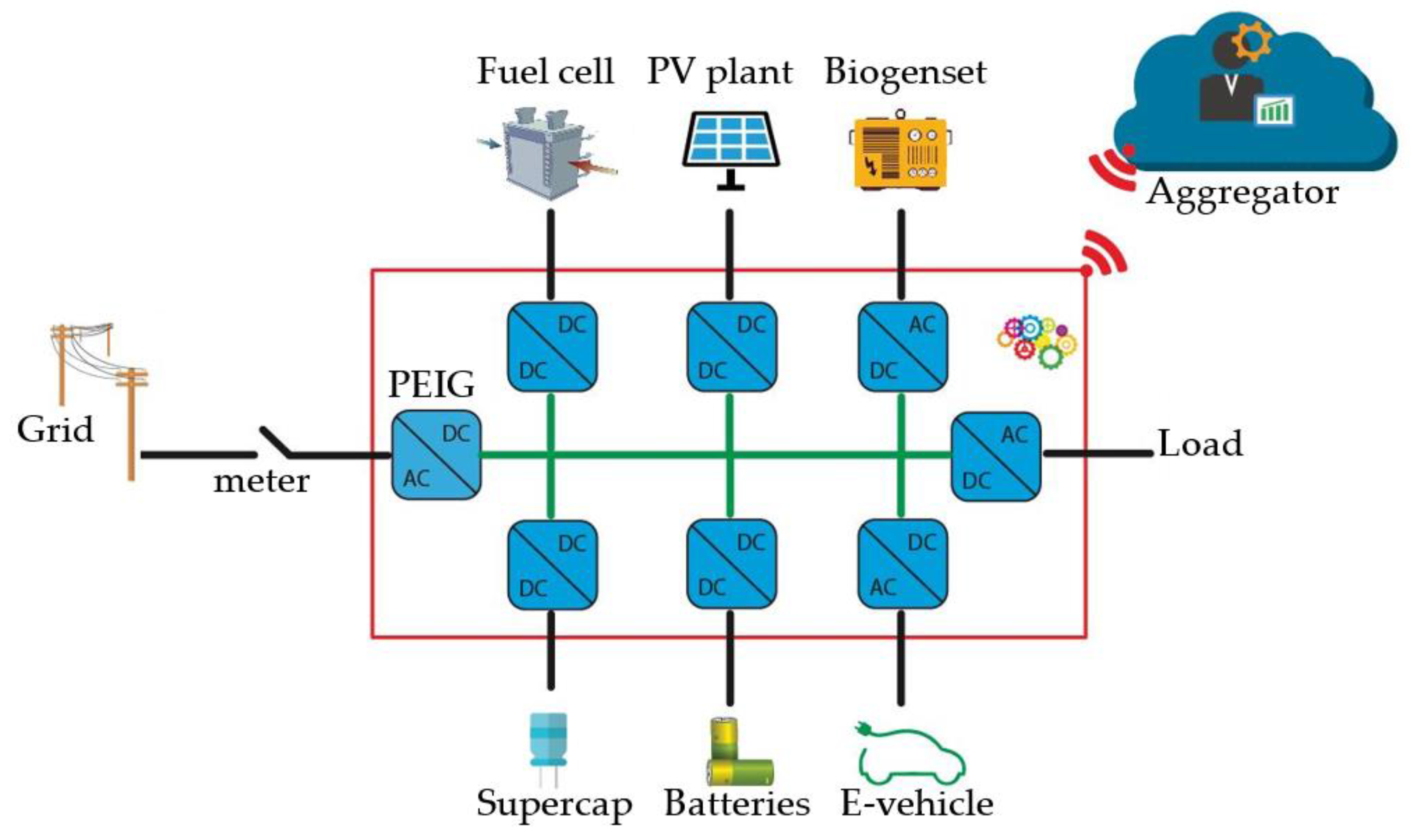
In this new framework, the DC Nanogrid (DCNG), a system that allows to interface on a common DC bus different resources such as renewable production plants, energy storage systems, interruptible and uninterruptible loads, having a rated power less than 10 kW is developed. All the resources are interfaced with the common DC bus with their own power converters. At the same time, a bidirectional DC/AC converter is used to connect the DCNG to the low voltage grid. The DCNG solution allows to interface more energy storage systems, if necessary, also characterized by different technologies, thus having different possible behaviors. When operating in grid-connected mode, it can manage different resources thus to reach a particular aim or to provide services to the grid. It can also be useful for a consumer’s community to reduce the energy cost and consumption, for economic scope maximizing the renewable electricity sharing.
The DC nanogrids offer important advantages over AC nanogrids. The DCNGs are characterized by cheapness, simplicity compared to AC microgrid where generally more components, such as converters, are required. The DC distribution allows to directly connect the sources on the bus without any synchronization process. Thus, there is a reduction of issues and an increase of the reliability of the system. Moreover, the reduced number of AC/DC converters allows to obtain increased efficiency, and at the same time, it also allows to operate in standalone mode. The DC distribution is chosen over the AC one because it facilitates the integration of most of the resources that actually are supplied in DC mode, such as energy storage systems or electronic loads [
1]. Furthermore, that solution gives the whole distribution system the peculiar characteristics of the UPS, guaranteeing the continuity of the service and the functioning of the island of various DGs. In this context, it is necessary to search for the best way to implement a performing control strategy.
In this paper, the authors focus on the use of multiple DCNGs for home applications in order to compose and create a renewable energy community capable of meeting the energy requirements of a REC through better synergies between the different energy carriers. In this way, RECs based on the use of nanogrids can become an instrument to allow the progress of the marginal territories, in particular, those territories around urban areas or remote areas. In this paper, the authors adopt the DC Bus Signaling (DBS) distributed control strategy for the power management of each individual nanogrid. Using the DBS strategy, it is possible to regulate the power flows among the different power sources, batteries, and in the utility grid through changes in the DC bus voltage of the nanogrid. In this way, the electronic converters connected to the DC bus coordinate each other without any direct communication. Each converter is assigned a voltage threshold and this threshold is used by the converter’s local controller to activate/deactivate itself and the operating mode.
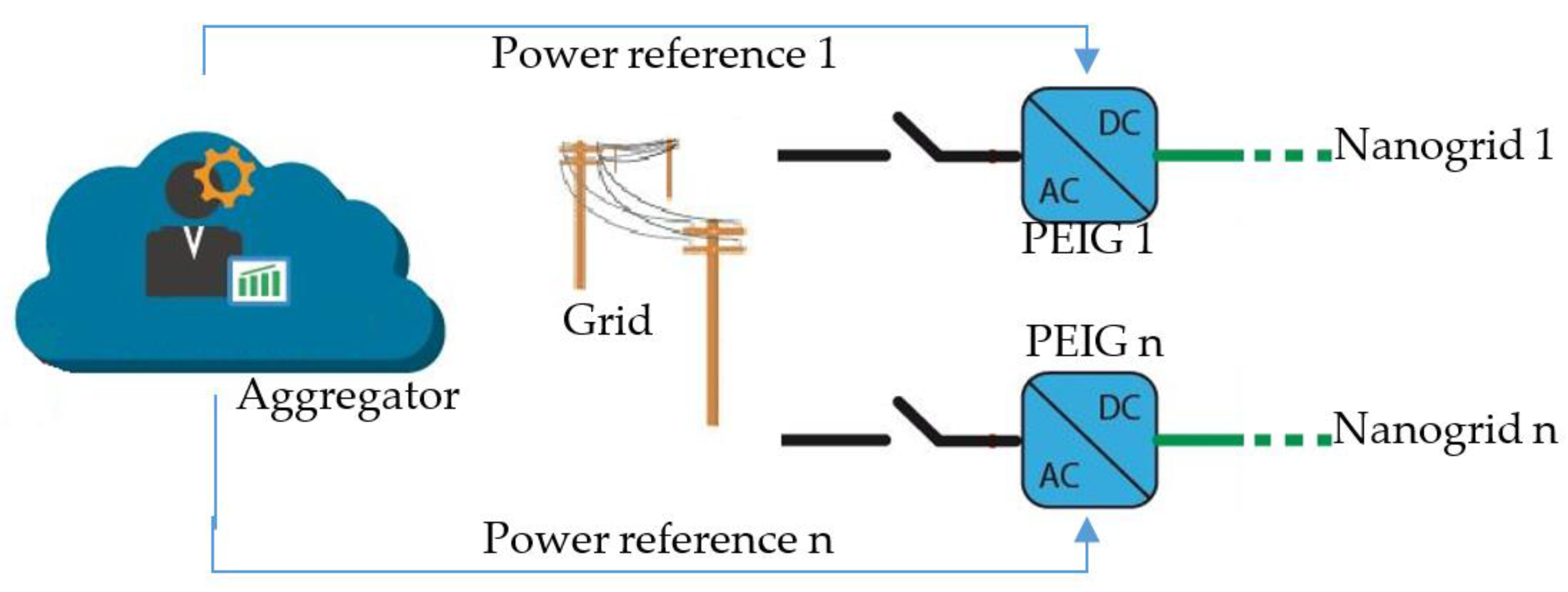
In the case of a REC, each nanogrid can receive power flow requests from the aggregator, the entity with legal status that interacts for the REC with grid operators (it represents the community with the external players, that can be a market operator or grid operators). To follow the power flow requests, it is necessary to control the grid converter power to the reference value, which can be the power result of an internal energy market optimization of the REC or can be required by the grid operator to achieve some goal. To make this possible the other power source interfaced with their own converter are managed according to the DBS strategy. It is necessary to empathize that the DBS strategy operates in any condition, both if it is required to control the power exchanged with the grid but also if it is not required, also if the nanogrid is operating in standalone mode. Indeed, this represents an advantage of the DBS strategy proposed by the authors, because the behavior is the same when “no service is provided” to “a service is provided” occurs. In addition, the value of the DC bus voltage of each nanogrid is communicated to the aggregator; providing this information allows the aggregator to evaluate the regulation capacity that each nanogrid can provide and which of the flexible resources present in each nanogrid provides that capacity.
The paper is structured as described below:
Section 2 presents the state of the art starting from the DC microgrids and ending with the control strategies proposed in the literature.
Section 3 presents the DBS control strategy applied to the nanogrids belonging to the energy communities. The section also illustrates the various operating modes of the nanogrid, both when it is not committed to providing any service to the aggregator and when it is (for example, balancing service). The
Section 4 illustrates the case study and the related numerical results obtained by the simulation when five nanogrids are connected to the utility grid and are operating as an energy community.
3. The DBS Control for Nanogrids Belonging to a REC
In this paper, the distributed DBS control strategy is adopted for the power management of a nanogrid for home applications belonging to a REC implementing the model proposed in [
43]. As recalled in the state of the art, the DBS control regulates the power flows from generators, from/to storage systems, and from/to the utility grid by means of changes in the DC bus voltage of the nanogrid. Thus, the electronic power converters belonging to the nanogrid and connected to the DC bus coordinate each other without any direct communication. Indeed, a voltage threshold is assigned to each converter and this voltage threshold is used by the local controller of the power converter to activate or change its own operating mode.
This section shows the modes of the DBS control for the power management of the nanogrid illustrated in
Figure 3, where four power electronic converters are connected in parallel to a common DC bus. The converter PEIP regulates for the power flow of the PV plant, the converter PEIB regulates for the bidirectional power flow of the batteries, the converter PEIL supplies the domestic loads, the converter PEIG regulates for the power flow at the point of common coupling between the nanogrid and the utility grid, i.e., the meter or the POD.
It is worth underlining that the implemented technique has no theoretical limits of application. The types of loads considered in this study are residential.
The DBS control proposed in this paper for the power management of the nanogrid of
Figure 3 has seven modes in all, where five modes regulate the operation of the nanogrid when the nanogrid is not committed to providing any service to the aggregator (e.g., balancing service), while two modes added to previous five to operate the nanogrid providing service to the aggregator. It is important to highlight the milestone achieved by the authors in designing the DBS control, since it lets to a better understanding: the operating modes of the DBS logic, which manages the energy flows of the nanogrid, do not change the behavior of the nanogrid both in the case in which “no service is provided” or in the case in which “a service is provided.” In addition, to the five operating modes of the DBS logic in the case in which “no service is provided”, when “a service is provided,” two other operating modes are added to these five operating modes.
The seven DBS operating modes or simply modes, the corresponding voltage references and the parameters are illustrated in
Figure 4 and reported in
Table 1.
3.1. DBS Modes for “No Service Is Provided”
This section illustrates the five modes of the DBS control that regulate the operation of the nanogrid in normal operating conditions, that means that the nanogrid is not committed in the provision of any service to the aggregator, i.e., “no service is provided.” These modes are numbered from Mode_1 to Mode_5, they are summarized in
Figure 4 and
Table 1 and the objective is to maximize the self-consumption. Worth noting that the sum of the locally generated energy and the locally stored energy, namely the energy means as in the third row of
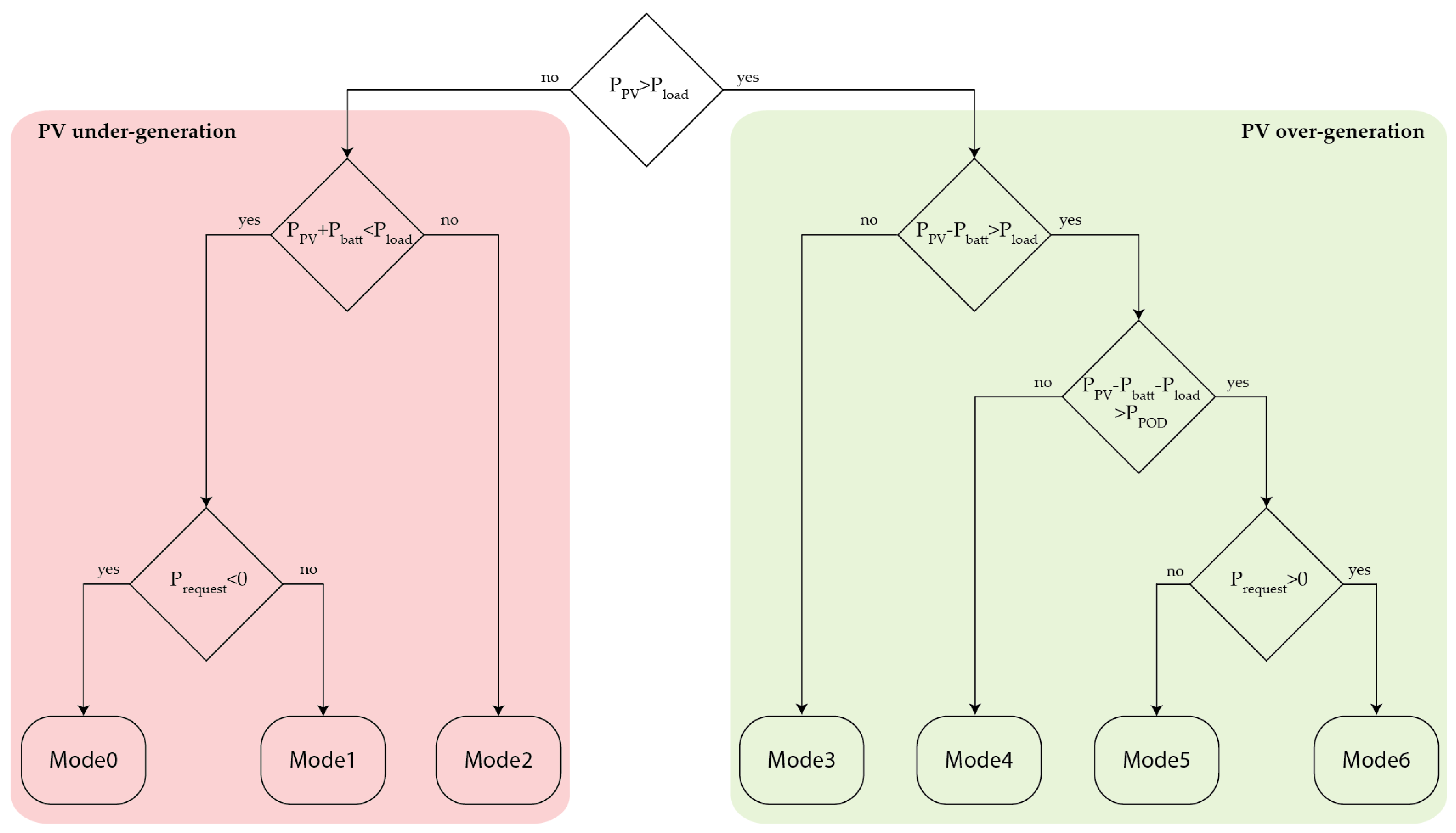
Table 1, grows from Mode_1 to Mode_5. For example, Mode_1 is the most recurring operating mode at night when the energy means are very low. Indeed, the energy provided by the PV plant is zero and the energy stored in the batteries is also zero because the stored energy has already been used to supply the loads during the late afternoon and evening. In contrast, Mode_5 is the most common mode of operation at sunny midday, and the energy means are very high. Indeed, the power provided by the PV plant is peak power or almost, family members are at work or school, the electrical loads are turned off, the batteries are fully charged. Thus, the over-generation is entirely exported to the utility grid. DBS modes are now described with details, with the help of the flow chart in
Figure 5.
Mode_1: the reference value for the DC bus voltage is V
ref = 710 V and the PEIG operates thus that the DC bus voltage remains close to this reference value. In Mode_1 the sum of power provided by the batteries and the power provided by the PV plant does not equal the load demand (see
Figure 5, PV under-generation). Therefore, the PEIG imports power from the electricity grid:
Since maximizing self-consumption is the main goal of the nanogrid, both PEIB and PEIP provide as much power as possible. Therefore, the PEIP tracks the Maximum Power Point (MPP) from the PV plant, whereas the PEIB discharges the batteries. The first column of
Table 1 summarizes the Mode_1: the reference value for the DC bus voltage is 710 V and this value is assigned to PEIG; the PEIB discharges the batteries. Therefore, a control voltage, V
crt, higher than the DC bus voltage and equal to 730 V is assigned to PEIB; the PEIP tracks the MPP from the PV plant, and the MPP power reference is assigned to PEIP.
Mode_2: the reference value for the DC bus voltage is V
ref = 730 V and the PEIB operates thus that the DC bus voltage remains close to this reference value. The PEIP tracks the MPP. Since the sum of the power provided by the batteries and the power provided by the PV plant entirely satisfies the load demand (see
Figure 5, PV under-generation); the PEIG regulates the power flow at the meter to zero (see the zero-power reference in
Table 1) thus as to maximize the self-consumption.
Mode_3: the reference value for the DC bus voltage is V
ref = 750 V and the PEIB operates thus that the DC bus voltage remains close to this reference value. The PEIP tracks the MPP and provides more power than the load demand (see
Figure 5, PV over-generation). In order to maximize the self-consumption, the PEIB recharges the batteries, entirely exploiting the over generation:
whereas the PEIG regulates the power flow at the meter to zero, i.e., P = 0 W.
Mode_4: the reference value for the DC bus voltage is V
ref = 770 V and the PEIG operates thus that the DC bus voltage remains close to this reference value. As in Mode_3, the PV plant tracks the MPP and generates more power than the load demand (see
Figure 5, PV over-generation); at the same time, the PEIB recharges the batteries and a control voltage lower than the DC bus voltage reference V
crt = 750 V, is assigned to the PEIB controller. Unlike Mode_3, the over-generation is not entirely stored in the batteries. Therefore, the PEIG exports power to the utility grid, maintaining the DC bus voltage close to the reference.
Mode_5: the reference value for the DC bus voltage is V
ref = 790 V, and the PEIP operates thus that the DC bus voltage remains close to this reference value. The power generated by the PV plant exceeds the load demand, it exceeds the power of batteries, it exceeds the contractual power at the POD (P
POD see
Figure 5, PV over-generation). Consequently, the PEIP stops tracking the MPP and starts regulating the DC bus voltage close to the reference value. The PEIB recharges the batteries as much as possible, and a control voltage lower than the DC bus voltage reference, V
crt = 750 V, is assigned to the PEIB controller. Similarly, the PEIG exports power to the utility grid as much as possible. The control voltage for this converter is V
crt = 770 V.
3.2. DBS Modes for “A Service Is Provided”
In
Figure 4, the five DBS control modes shown above regulate the operation of the nanogrid when the nanogrid is not committed to providing any balancing service to the aggregator; these modes are still valid for governing the nanogrid when the nanogrid is committed in providing a balancing service, but two additional modes are necessary to ensure a safe operation. These two additional modes are named Mode_0 and Mode_6, they are reported in the last two columns of
Table 1 and described below.
Mode_0: the reference value of the DC bus voltage is equal to V
ref = 690 V and the PEIG operates thus that the DC bus voltage remains close to the reference value. Mode_0 is the lower limit between the operating modes; the nanogrid operates in Mode_0 because it was operating in Mode_1 and the aggregator asked the nanogrid to export power to the utility grid (Prequest < 0) (see
Figure 5, PV under-generation). The aggregator’s request worsens the already-critical condition since the PEIG increases the power exported to the utility grid, but the energy means are very low. The PEIP tracks the MPP, but the power generation of PV plant is low or absent. Similarly, PEIB discharges the batteries as far as possible but the SOC of batteries is low or null. Since the sum of the powers provided by the PV plant and the batteries is not enough, the DC bus voltage inevitably decreases: the DC bus voltage leaves 710 V, and it decreases up to 690 V when Mode_0 is activated. Now the nanogrid exports the maximum-possible power to the utility grid and the minimum-possible value of DC bus voltage is reached; the PEIG regulates for the power flow at the meter and ensures that the DC bus voltage remains higher or equal to V
ref = 690 V.
Mode_6: the reference value of the DC bus voltage is equal to V
ref = 810 V and the PEIG operates thus that the DC bus voltage remains close to the reference value. Mode_6 is the upper limit between the operation modes; the nanogrid operates in Mode_6 because it was operating in Mode_5 and the aggregator asked the nanogrid to import power from the utility grid (Prequest > 0) (see
Figure 5, PV over-generation). The aggregator’s request worsens the already-critical condition since the PEIG increases the power imported from the utility grid, but the energy means are very high. The PEIP stops generating power, imposing P
ref = 0W whereas the PEIB recharges the batteries as much as possible. If batteries’ recharge is not fast enough then the DC bus voltage inevitably increases up to 810 V when Mode_6 is activated. Now the nanogrid imports the maximum-possible power from the utility grid and the maximum-possible value of DC bus voltage is reached; the PEIG regulates for the power flow at the meter and ensures that the DC bus voltage remains lower or equal to V
ref = 810 V.
The power converters of the nanogrid, the PEIB, PEIL, and PEIP (
Figure 3) can only operate based on the developed DBS strategy. Then, the individual converters track the assigned reference based on the voltage level of the DC bus, based on the modalities established by the DBS strategy.
The PEIG interfaces the nanogrid to the grid and manages the exchange of electricity energy flows, as illustrated in the control scheme of
Figure 6. The PEIG can operate based on DBS control strategy tracking the DC bus voltage reference (V
ref) if there is no request from the aggregator. If the aggregator requires the power PSETPOINT to the nanogrid, the PEIG control changes, from voltage control to current control, to follow the current reference value (I
ref), calculated as PSETPOINT divided by the PEI output voltage (VPCC) (see
Figure 6). A principal converter, called master converter, aims to regulate the DC bus voltage characterizing each operation mode. When a nanogrid, due to its regulation capacity limits, cannot satisfy the aggregator’s request, then the saturation levels of the nanogrid are reached, which correspond to the maximum (810 V) or minimum (690 V) voltage level of the DC bus. The PEIG is able to recognize and assess this operational condition and to communicate that the aggregator request cannot be satisfied.
4. The Case Study and the Numerical Results
Figure 7 illustrates the case study of this paper: five modern houses or nanogrids, equipped with a set of PV plant installed on the rooftop and a set of lithium-ion batteries. It is worth underlining that the effectiveness of the proposed DBS for a single nanogrid, demonstrating how the single converters interfacing the nanogrid sources (PV plant, battery storage) operates based on the DC bus voltage changes, was reported by the authors in previous papers [
10,
11,
44]. As before mentioned, the effectiveness of DBS is not influenced form the load variability, thus in this paper, the load modeling has not been investigated otherwise faced by the authors in [
45,
46].
The scheme of each nanogrid is illustrated in
Figure 3 where PEIP, PEIB, PEIL, and PEIG are power electronic converters, which regulate for the nanogrid’s power flows; more precisely, PEIP regulates the power generation of PV plant, PEIB charges/discharges the batteries, PEIL supplies the loads, PEIG joins the nanogrid to the grid and regulates for the power flow at the meter. An intelligent agent supervises these four electronic power converters. This agent, widely known as Home Energy Management System (HEMS), governs the nanogrid and typically maximizes the self-consumption to reduce the electricity bill. Each HEMS communicates with an aggregator. In this paper, the authors consider conventional communication over the Internet via a domestic modem/router and suppose this technology is quite robust, reliable, and secure for this study. The aggregator is the intermediary between the five nanogrids, i.e., the renewable energy community under study, and the grid operators DSO and TSO. This intermediation is intended to provide balancing services. In this sense, the aggregator coordinates the five nanogrids, thus that the sum of power flows they exchange with the electricity grid equals, time by time, the desired value as better explained below.
It should be noted that, for the communication between DSO/TSO, aggregator, and HEMS, as an alternative to what is described above, one of the protocols provided for communication between DSO/TSO and active users can also be used, as reported in [
43,
47].
4.1. The Behavior of a Single Nanogrid
A test of the control strategy presented was performed on NanoGrid1 (NG1) only, to show the behavior of a single nanogrid and of the individual power converter, in terms of DC bus voltage and power profiles, in case of requests from the aggregator.
Figure 8 shows the voltage of the DC bus (V
DC_bus) of NG1, the power requests from the aggregator to NG1 (P
setpoint), and the response of NG1, i.e., the power exchanged with the grid by NG1 (P
grid). In this test, the request by the aggregator varies every 15 min for a total period of 90 min.
Figure 9 shows in detail the power profiles of the NG1 during the test. In particular, the SOC and the power of the battery storage (P
batt), the power profile of the PV plant generation (P
PV), and the two power profiles of the load are represented. In this test, the load was split into critical and non-critical, P
critical_load and P
load, respectively. The critical load absorbs a constant power in 90 min equal to 1.5 kW, while the non-critical load, equal to 0.5 kW, can also be disconnected in case of need.
In the first 15 min interval, the setpoint request is to feed into the grid a power of 1.5 kW. The NG1 feeds into the grid a P
grid equal to −1.5 kW (
Figure 8) and the operating mode is Mode_4 (V
DC_bus = 770 V). In fact, as can be seen from
Figure 9, the PV delivers a power of 6 kW, of which 2.5 kW are used to charge the battery storage (the SOC increases), 2 kW are used to power the loads, critical and not, therefore, 1.5 kW are fed into the grid, which coincides with the aggregator’s request.
In the second interval, the aggregator asks to reduce the input into the grid by 0.5 kW, then the power exchanged with the grid is reduced to −1 kW (
Figure 8) and the DC bus voltage increases, passing from Mode_4 to Mode_5 (V
DC_bus = 790 V). As can be seen from
Figure 9, the powers of the loads and battery storage remain unchanged, which already absorbs maximum power, but the production of the PV plant is modulated to meet the demand of the aggregator, the PV does not operate in MPP but regulates the DC bus voltage.
In the third interval, the aggregator asks to draw power of −3 kW from the grid, and the NG1 follows the required profile by drawing 3 kW from the grid, remaining to always operate in Mode_5 (
Figure 8). In fact, as can be seen from
Figure 8, the production of the PV system is further reduced by 3 kW compared to the previous range, going from 5.5 kW to 1.5 kW, while loads absorb the power and battery storage still remain unchanged.
In the fourth interval, the aggregator request goes from −3 kW to −5 kW, then the NG1 tries to follow the new setpoint, but without succeeding. In fact, the P
grid is limited to 4.5 kW, and the DC bus voltage reaches the maximum value of 810 V (Mode6—
Figure 8). From
Figure 9, the battery storage absorbs the maximum power (−2.5 kW), the loads are all powered (2 kW), and the PV plant reduces production to 0 kW.
In the fifth interval, the aggregator setpoint goes from −5 kW to 5 kW, hence a request for grid injection of −5 kW. As can be seen from
Figure 8, the request is satisfied, and the DC bus voltage drops to 730 V (Mode_2). From
Figure 9, it can be seen how this condition is reached by returning the PV plant to work in MPP (6 kW), the loads are powered (2 kW), while the battery storage passes from the charged condition to the discharged condition, with power of 1 kW.
Finally, in the last interval, the aggregator increases the request for injection into the grid from 5 kW to 7.5 kW. In this condition, the maximum power that the NG1 can supply to the grid is −7 kW. Therefore, the NG1 operates in Mode_0, with a DC bus voltage of 690 V (
Figure 8). From
Figure 9, it is possible to observe that this operating condition is reached by leaving the PV plant in MPP at 6 kW, the battery storage increases the output from 1 kW up to the maximum power of 2.5 kW, the non-critical loads are disconnected (0.5 kW) trying to follow the setpoint.
4.2. The Request for a Balancing Service
In the case study of this paper, the authors assume that the DSO or TSO urgently need a balancing service; at this scope, the authors suppose that rapid 6-steps exchange of information such as that schematically shown in
Figure 10 realistically takes place.
At step 1, the DSO/TSO sends a query to the aggregator because this aggregator represents the energy community of five nanogrids sited into a geographical perimeter. The DSO/TSO asks the energy community for a balancing service. That is DSO/TSO asks for (a) the maximum average power that the energy community can provide to the utility grid for an hour and (b) the price for this service. The aggregator has to reply in a very short time, e.g., one minute. In addition, if the DSO/TSO accepts the offer, i.e., the price for the balancing service, then the energy community has to provide the balancing service within a very short as well, e.g., 5 min.
At step 2, the aggregator interrogates the five HEMSs, which manage the five nanogrids. Each HEMS calculates the maximum average power that the nanogrid may export to the utility grid in the next hour. In step 3, each HEMS replies to the aggregator communicating an average hourly power. At step 4, the aggregator sums the average hourly powers and calculates a price for the balancing service; then it replies to the DSO/TSO, communicating the maximum average hourly power and the price. At step 5, the DSO/TSO accepts the offer, thus the aggregator has to activate the balancing service after 5 min. At step 6, the aggregator promptly informs the HEMSs thus to assign a setpoint to each of the five converters, i.e., the PEIGs. After step 6, the communication between aggregator and DSO/TSO stops. On the contrary, the communication between the aggregator and the HEMSs remains alive and strong because, by now, the aggregator monitors the nanogrids, and the PEIGs, in particular, in real time thus to decide and implement corrective actions if necessary.
4.3. Numerical Results
When at step 2 of
Figure 10 the aggregator queries the HEMSs, each HEMS rapidly executes some numerical calculations to quantify its own interest and capability to participate in the balancing service. This is because, as anticipated, each HEMSi governs the
i-th nanogrid (NG
i) to maximize the self-consumption and minimize the electricity bill. Now each HEMS must decide if and how to penalize the self-consumption for providing the balancing service to the DSO/TSO. These calculations certainly consider the technical data reported in
Table 2: the peak power of the PV plant installed on the rooftop, the power, the Amps-per-Hour and the current SOC of the batteries, the contracted power to import, and export at the POD.
It is relevant to underline that the operation of DBS approach is completely independent from the user configuration in terms of PV plant and battery storage size and so on the load profile. The operation of DBS depends only on the instantaneous power capacity of the PV plant in terms of generation and the SOC of battery storage. Each source is used until its maximum power capacity to satisfy the load demand and, in such cases, the aggregator/DSO request, giving priority to PV plant generation. The sizing of PV plant and battery storage is not the scope of this paper, and it may be considered in the results of the approach proposed by the authors in [
46,
48].
First of all, the HEMS1 evaluated the normal operation of the nanogrid in the absence of a balancing service. It estimated the load demand for the hour after with a 15-min time resolution; the demand increased from 2.10 kW to 3.00 kW and then decreased to 2.40 kW as reported in first row of
Table 3.
At the same time, HEMS1 estimated the average power generated by PV plant for the hour after; this power grew from 3.74 kW up to 4.55 kW. The difference between the demand and generation returned a positive result, i.e., an over-generation; therefore, the SOC increased from 76.83% to 97.84%. Given the normal operation, the HEMS1 proceeded to evaluate the operation of the nanogrid in the presence of a balancing service. First, the HEMS1 supposed that the positive balance does not recharge the batteries, but it is exported to the utility grid (see the third row of
Table 4). After that, the HEMS1 supposed that the batteries also supply the utility grid at the maximum power, 3.00 kW, and up to the minimum value of the SOC, 20% (see the fourth row of
Table 4). The conclusion was the set of four values reported in the last row of
Table 4; this is the answer that HEMS1 returned to the aggregator, and it indicated that the NG1 can export 4.64 kW in the 1st quarter, 4.61 kW in the 2nd quarter, etc.
At the same time, HEMS2, HEMS3, HEMS4, and HEMS5 perform similar calculations; the results of all these calculations are reported in
Table 5. Worth noting that the HEMS5 reply to a null response as reported in
Table 6; it means that the NG5 will not contribute to the balancing service. This is because the local demand is greater than the local generation, therefore, HEMS5 first discharges the batteries to supply local loads up to the deep-of-discharge (DoD), after that the HEMS5 imports power from the utility grid as soon as the depth of discharge of the batteries is reached.
As soon as all the HEMSs replies were received, the aggregator considers the minimum value provided by each HEMSs and curtails it to 20% to achieve a safety margin; the values thus obtained were the set points for each nanogrid as reported in
Table 7. At the same time, the aggregator communicates to the DSO/TSO the willingness to provide the utility grid an average power equal to 15.58 kW for one hour. The aggregator also communicates a price evaluated by a method that is the subject of a future paper.
From now, the aggregator starts monitoring the power flows at the PODs; the authors assume that each HEMS sends the average value of power flow at its own POD every 2–3 s. This communication is also useful to check the smooth functioning of the community; as an example, if the communication between the aggregator and a nanogrid ceases, then corrective action is evidently necessary.
4.4. Case of the Communication between Aggregator and Nanogrid
Meanwhile the balancing service is active, the aggregator and HEMSs communicate with each other every 2–3 s. The authors suppose that if the communication between the aggregator and a nanogrid ceases, then the aggregator sends to the HEMS three reminders, one every 5 s; if these three attempts fail, then the aggregator excludes this nanogrid and assigns the service to the remaining HEMSs according to a priority criterion. The priority is shown in the last column of
Table 7 and reflects the percentage of participation of each nanogrid to the balancing service. The first in the ranking is the NG2, since at step 3 of
Figure 10 the HEMS2 gave the aggregator the higher availability of power injection. In this way, the HEMS2 gained the right to be consulted as first in the case of real-time adjustments.
The authors assume that the communication between the aggregator and the HEMS4 ceases at the beginning of the 3rd quarter when the aggregator excludes HEMS4. Worth noting that the HEMS4 is aware that when the communication fails the remaining nanogrids will provide the whole service. Therefore, from now, the HEMS4 governs the nanogrid, as usual, that is maximizing the self-consumption.
In accordance with the priority criterion, the aggregator asks the HEMS2 for additional power equal to 3.50 kW for the 3rd and 4th quarters. Unfortunately, HEMS2 cannot accept the request in full. Considering that the contracted power at the POD was 6.00 kW and that a power equal to 4.50 kW was already exported to the utility grid, the HEMS2 accepts an additional power equal to 1.50 kW, as shown in
Table 8. Therefore, the aggregator asks the HEMS1 for an additional power equal to 2.00 kW for the 3rd and 4th quarters. In addition, the HEMS1 cannot accept the request in full. Considering that the nominal power of the batteries was 3.00 kW and that the batteries already delivered a part of the service, the HEMS1 accepts an additional power equal to 0.88 kW and to 1.75 kW for the 3rd and 4th quarters, respectively, as shown in
Table 8.
Finally, the aggregator asks the HEMS3 for the remaining values that is an additional power equal to 1.12 kW for the 3rd quarter and 0.25 kW for the 4th quarter. Due to the capacity of the batteries, the HEMS3 partially accepts the request for the 3rd quarter, 0.91 kW instead of 1.12 kW and fully accepts the request for the 4th quarter, 0.25 kW. After these assignments, the aggregator calculates that a power equal to 0.21 kW was still missing for the 3rd quarter. The NG3 was the only one capable of providing this additional power but it can supply this power to the utility grid in the 4th quarter instead of the 3rd quarter. The aggregator decides to ask HEMS3 for this additional power, as reported in
Table 8. The aggregator adopts this choice because, by doing so, the electrical energy gave the community to the utility grid to exactly fulfill the agreement with the TSO/DSO. On the contrary, the average power for each quarter was not equal to the agreed value, i.e., 14.70 kW, since it was slightly lower in the 3rd quarter and slightly higher in the 4th quarter. The penalties for this imperfection are the subject of future studies.
4.5. The Map of Voltages Detected at the DC Bus of Each Nanogrid
As mentioned above, the aggregator communicates with the HEMSs in order to monitor the power flows at the PODs. In addition to power flows, the HEMSs might inform the aggregator also about the voltage measured at the local DC bus; sharing this value could contribute to improve the aggregator’s supervision of the energy community. On this reference,
Table 9 reports the most frequent DC bus voltage values HEMSi measured for each quarter; the authors assume that a value is the most frequent if its frequency is higher than 85%.
For the NG1, NG2, and NG3, the most frequent value was 750 V for all quarters. Therefore, the aggregator deduces that these nanogrids delivered the balancing service mainly thanks to the joint contribution of the PV plant and the batteries. The value 750 V does not specify the ratio between the contributes given by the PV plant and the batteries. However, it clearly indicates that the residential battery storage system provided a contribution in delivering a balancing service for all the time.
For the NG4, the most frequent value in the 1st quarter was 790 V; therefore, the aggregator deduces that the HEMS4 almost certainly faced an unexpected excess of local generation or an unexpected decrease of local demand. Moreover, this is true because the authors superimposed a drastic reduction of local demand to 0.10 kW as a heavy disturbance. Since the SOC of the batteries was 100%, the over-generation caused the constant increase of the DC bus voltage up to 790 V when the HEMS4 substituted the MPPT of the PV converters for the constant-voltage operation mode. In this quarter of an hour, the batteries gave no contribution to the balancing service. In the 2nd quarter, the most frequent value was 770 V. Therefore, the aggregator deduces that the SOC of the batteries remained equal to 100% and that the batteries gave no contribution to the balancing service jet.
Finally, the most frequent value of DC bus voltage for the NG5 was 730 V thus the aggregator deduces why that the HEMS5 did not participate to the balancing service: the local generation together with the batteries were not sufficient to supply the local demand, therefore, no power could be exported to the utility grid.
5. Conclusions
This paper proposed the DC Bus Signaling (DBS) control strategy as distributed and decentralized control approach to coordinate and manage several nanogrids aggregated in a Renewable Energy Community (REC).
The proposed control strategy is used not only to control locally the energy needs of a single nanogrid but also by a set of five DC nanogrids, forming a REC, to provide an upward balancing service. To this aim, each nanogrid exports power to the grid exploiting the local overgeneration and the charge of the battery energy storage system.
The effectiveness of the proposed strategy was assessed via numerical experiments. In the case study, the power outputs of photovoltaic generators of four nanogrids exceed the respective load demands and the states of charge of batteries are within 70–100%. Therefore, these nanogrids reply to DSO/TSO requests by providing a 15.58 kW upward balancing service.
The effectiveness of the proposed control strategy has been further verified considering the N-1 criteria, i.e., the communication between the aggregator and one nanogrid fails. Consequently, the aggregator recalculates the contribution of each nanogrid to the balancing service, sharing the service quota assigned to the nanogrid, which is no longer available.
Lastly, knowing the value of the DC bus voltage of each nanogrid facilitates the aggregator in coordinating the community because the aggregator is thus informed about the service capacity that each nanogrid can provide and about the energy resources that each nanogrid uses to provide its own contribution to the balancing service.
The next future works are focused on three points: how to evaluate the price for the service that the aggregator asks to the nanogrid management; how to distribute the penalties among the various nanogrids of the REC in case of non-compliance with the required service; the implementation of an experimental test.


 ,
, 


