
Microwave Technology Using Low Energy Concentrated Beam for Processing of Solid Waste Materials from Rapana thomasiana Seashells

 ,
,  ,
,  ,
,  ,
,
Abstract
:1. Introduction
2. Materials and Methods
2.1. Materials
2.2. Methodology
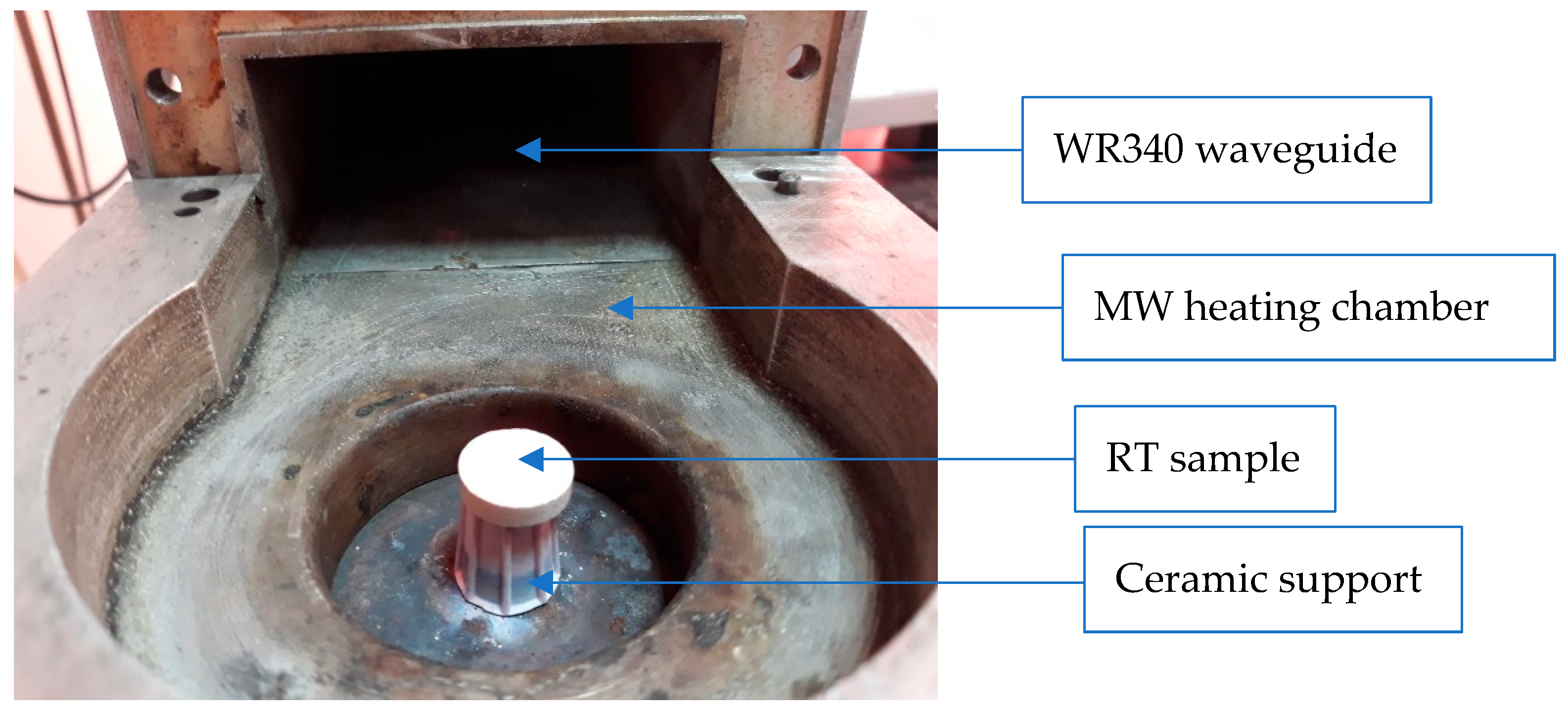
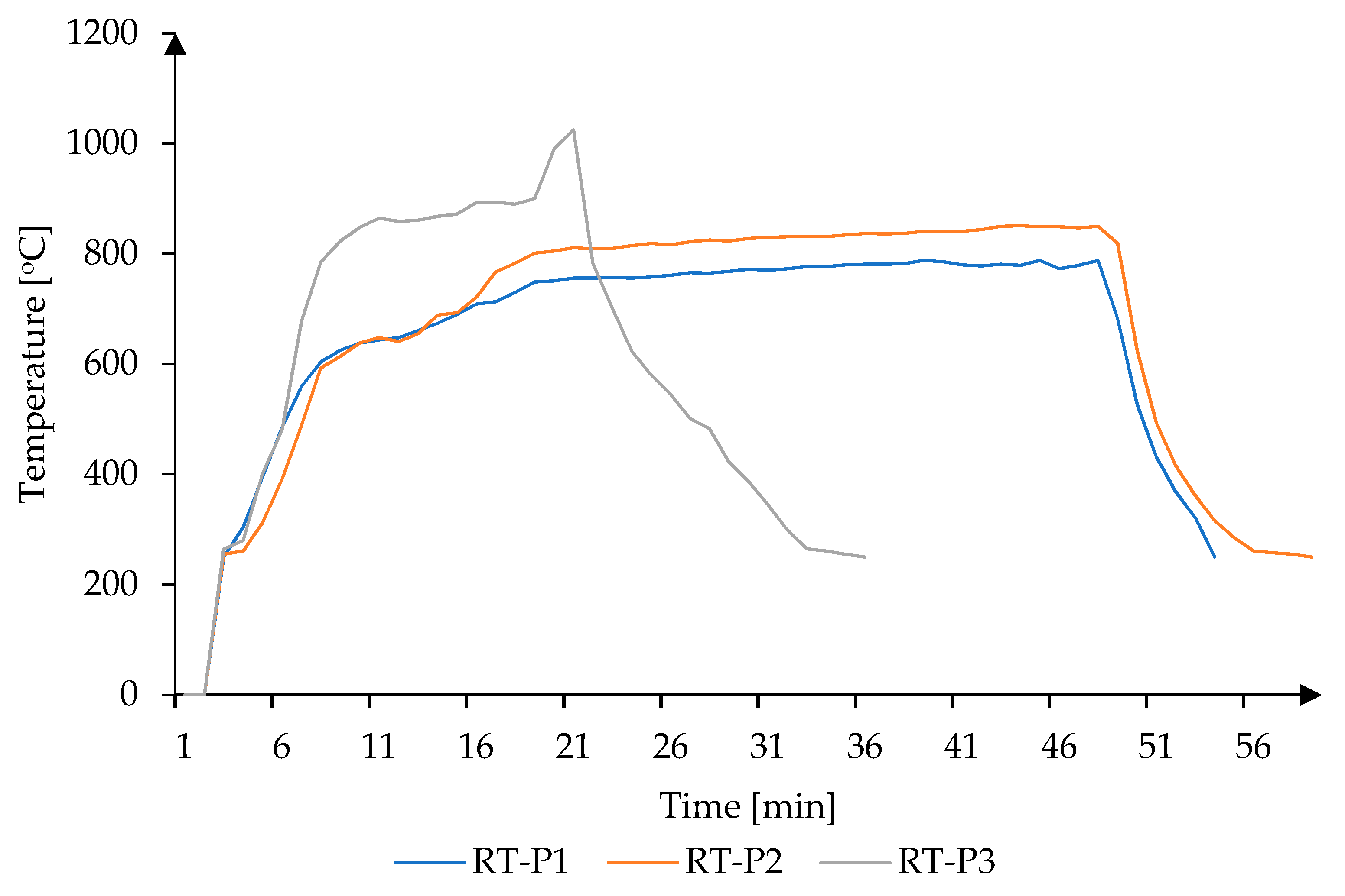
2.2.1. Direct Microwave Heating of the Samples
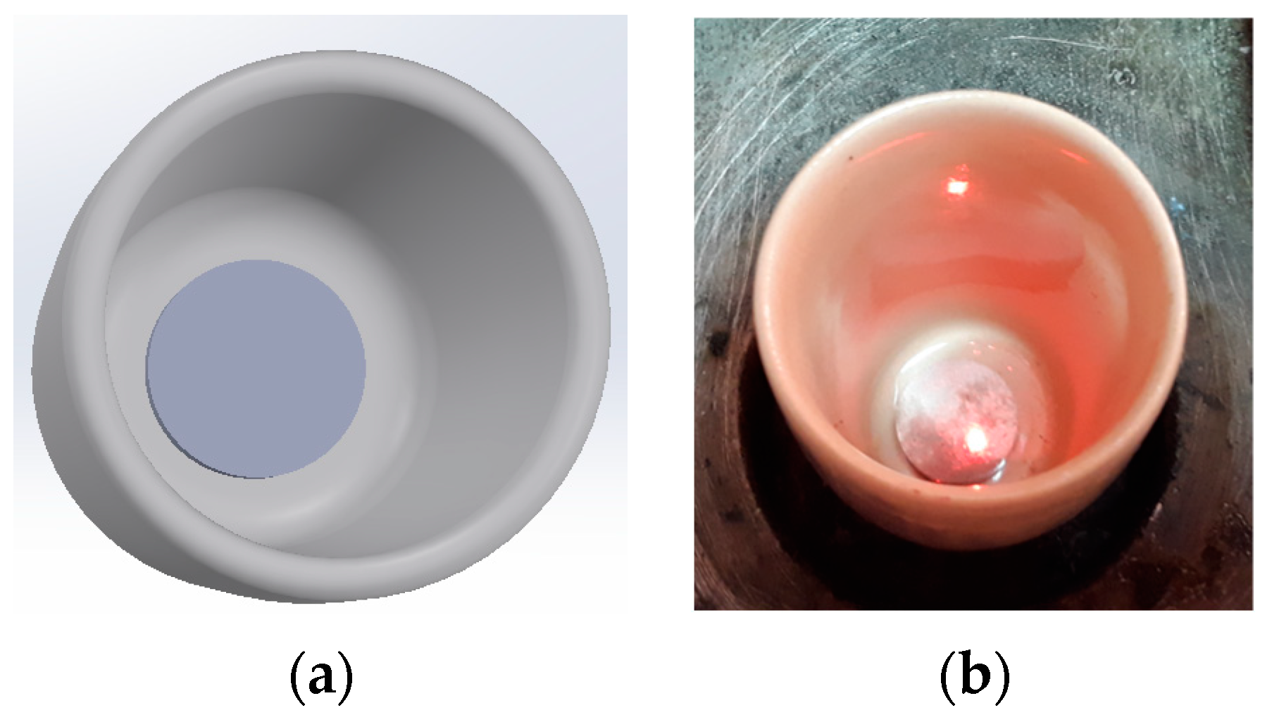
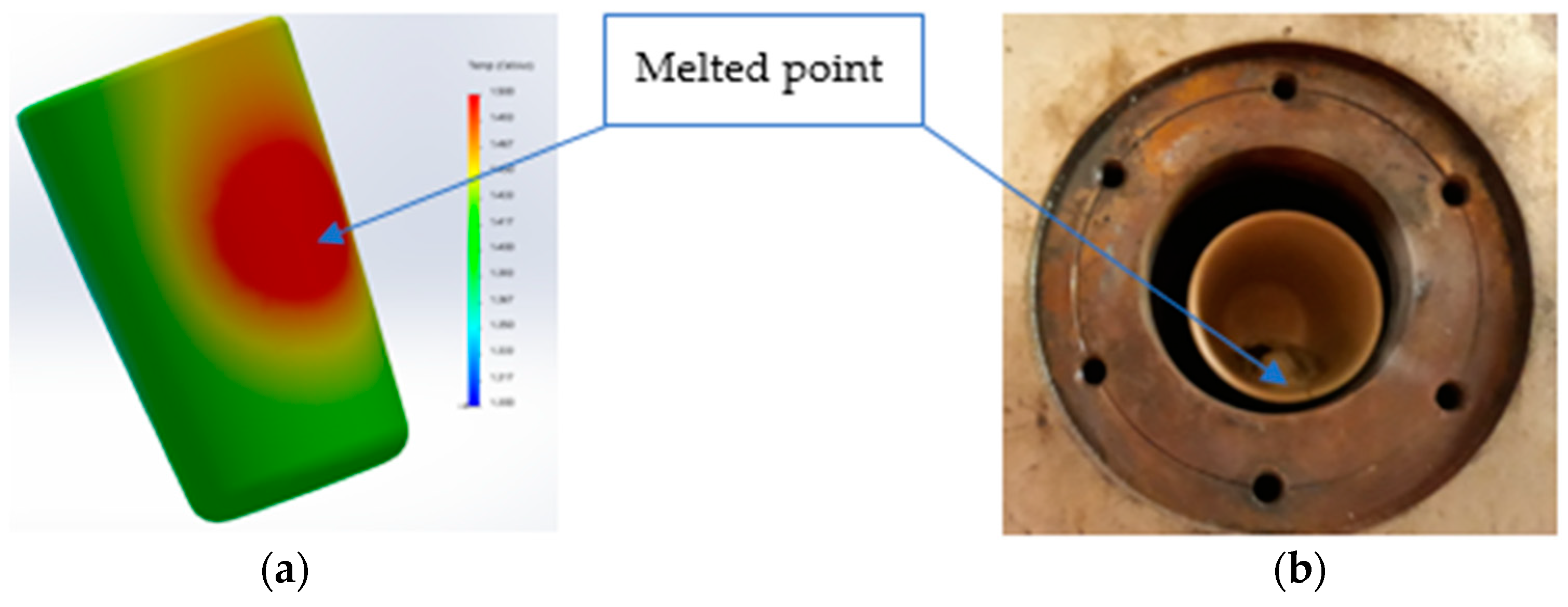
2.2.2. Hybrid Microwave Heating of the Samples
2.2.3. Resistance Heating of the Samples
3. Results
4. Discussion
5. Conclusions
Author Contributions
Funding
Institutional Review Board Statement
Informed Consent Statement
Data Availability Statement
Acknowledgments
Conflicts of Interest
References
- Ehrlich, H. Marine Biological Materials of Invertebrate Origin, 1st ed.; Springer Nature Switzerland AG: Cham, Switzerland, 2019; pp. 1–209. [Google Scholar]
- Mora, C.; Tittensor, D.P.; Adl, S.; Simpson, A.G.B.; Worm, B. How many species are there on earth and in the ocean? PLoS Biol. 2011, 9, e1001127. [Google Scholar] [CrossRef] [Green Version]
- Khrunyk, Y.; Lach, S.; Petrenko, I.; Ehrlich, H. Progress in modern marine biomaterials research. Mar. Drugs 2020, 589–635. [Google Scholar] [CrossRef] [PubMed]
- Powers, D.A. New frontiers in marine biotechnology: Opportunities for the 21st century. In Marine Biotechnology in the Asian Pacific Region; SAREC: Bangkok, Thailand, 1995. [Google Scholar]
- Leary, D.; Vierros, M.; Hamon, G.; Arico, S.; Monagle, C. Marine genetic resources: A review of scientific and commercial interest. Mar. Policy 2009, 33, 183–194. [Google Scholar] [CrossRef]
- Binnewerg, B.; Schubert, M.; Voronkina, A.; Muzychka, L.; Wysokowski, M.; Petrenko, I.; Djurović, M.; Kovalchuk, V.; Tsurkan, M.; Martinovic, R.; et al. Marine biomaterials: Biomimetic and pharmacological potential of cultivated Aplysina aerophoba marine demosponge. Mater. Sci. Eng. C Mater. Biol. Appl. 2020, 109, 110566–110577. [Google Scholar] [CrossRef] [PubMed]
- Wan, M.-c.; Qin, W.; Lei, C.; Li, Q.-h.; Meng, M.; Fang, M.; Song, W.; Chen, J.-h.; Tay, F.; Niu, L. Biomaterials from the sea: Future building blocks for biomedical applications. Bioact. Mater. 2021, 6, 4255–4285. [Google Scholar] [CrossRef] [PubMed]
- Lalzawmliana, V.; Anand, A.; Prasenjit, M.; Shubhamitra, C.; Kundu, B.; Samit Nandi, K.; Narsinh, L. Thakur. Marine organisms as a source of natural matrix for bone tissue engineering. Ceram. Int. 2019, 45, 1469–1481. [Google Scholar] [CrossRef]
- Ghaly, A.; Ramakrishnan, V.; Brooks, M.; Budge, S.; Dave, D. Fish processing wastes as a potential source of proteins, amino acids and oils: A critical review. J. Microb. Biochem. Technol. 2013, 5, 107–129. [Google Scholar]
- Lee, M.; Tsai, W.; Chen, S. Reusing shell waste as a soil conditioner alternative? A comparative study of eggshell and oyster shell using a life cycle assessment approach. J. Clean. Prod. 2020, 265, 121845. [Google Scholar] [CrossRef]
- Alvarenga, R.A.F.d.; Galindro, B.M.; Helpa, C.d.F.; Soares, S.R. The recycling of oyster shells: An environmental analysis using Life Cycle Assessment. J. Environ. Manag. 2012, 106, 102–109. [Google Scholar] [CrossRef] [PubMed]
- Iribarren, D.; Moreira, M.T.; Feijoo, G. Implementing by-product management into the life cycle assessment of the mussel sector. Resour. Conserv. Recycl. 2010, 54, 1219–1230. [Google Scholar] [CrossRef]
- Sowmya, R.; Ravikumar, T.M.; Vivek, R.; Rathinaraj, K.; Sachindra, N.M. Optimization of enzymatic hydrolysis of shrimp waste for recovery of antioxidant activity rich protein isolate. J. Food Sci. Technol. 2014, 51, 3199–3207. [Google Scholar] [CrossRef] [PubMed] [Green Version]
- De Holanda, H.D.; Netto, F.M. Recovery of components from shrimp (Xiphopenaeus kroyeri) processing waste by enzymatic hydrolysis. J. Food Sci. 2006, 71, C298–C303. [Google Scholar] [CrossRef]
- Zhang, K.; Zhang, B.; Chen, B.; Jing, L.; Zhu, Z.; Kazemi, K. Modeling and optimization of Newfoundland shrimp waste hydrolysis for microbial growth using response surface methodology and artificial neural networks. Mar. Pollut. Bull. 2016, 109, 245–252. [Google Scholar] [CrossRef] [PubMed]
- El-Fattah, M.A.; El Saeed, A.M.; Azzam, A.M.; Abdul-Raheim, A.-R.M.; Hefni, H.H.H. Improvement of corrosion resistance, antimicrobial activity, mechanical and chemical properties of epoxy coating by loading chitosan as a natural renewable resource. Prog. Org. Coat. 2016, 101, 288–296. [Google Scholar] [CrossRef]
- Ge, H.; Zhao, B.; Lai, Y.; Hu, X.; Zhang, D.; Hu, K. From crabshell to chitosan-hydroxyapatite composite material via a biomorphic mineralization synthesis method. J. Mater. Sci. Mater. Med. 2010, 21, 1781–1787. [Google Scholar] [CrossRef] [PubMed]
- Vijayaraghavan, K.; Winnie, H.Y.N.; Balasubramanian, R. Biosorption characteristics of crab shell particles for the removal of manganese (II) and zinc (II) from aqueous solutions. Desalination 2011, 266, 195–200. [Google Scholar] [CrossRef]
- Monteiro, R.J.R.; Lopes, C.B.; Rocha, L.S.; Coelho, J.P.; Duarte, A.C.; Pereira, E. Sustainable approach for recycling seafood wastes for the removal of priority hazardous substances (Hg and Cd) from water. J. Environ. Chem. Eng. 2016, 4, 1199–1208. [Google Scholar] [CrossRef]
- Jeon, C. Adsorption behavior of silver ions from industrial wastewater onto im- mobilized crab shell beads. J. Ind. Eng. Chem. 2015, 32, 195–200. [Google Scholar] [CrossRef]
- Joseph Sherin, M.; Krishnamoorthy, S.; Paranthaman, R.; Moses, J.A.; Anandharamakrishnan, C. A review on source-specific chemistry, functionality, and applications of chitin and chitosan. Carbohydr. Polym. Technol. Appl. 2021, 2, 100036. [Google Scholar]
- Dima, J.B.; Sequeiros, C.; Zaritzky, N. Chitosan from marine crustaceans: Production, characterization and applications. In Biological Activities and Application of Marine Polysaccharides; InTech: Rijeka, Croatia, 2017. [Google Scholar]
- Oyatogun, G.; Esan, T.; Akpan, E.; Adeosun, S.; Popoola, A.; Imasogie, B.; Soboyejo, W.; Afonja, A.; Ibitoye, S.; Abere, V. Handbook of Chitin and Chitosan; Elsevier: Amsterdam, The Netherlands, 2020. [Google Scholar]
- Cheung, R.C.F.; Ng, T.B.; Wong, J.H.; Chan, W.Y. Chitosan: An update on potential biomedical and pharmaceutical applications. Mar. Drugs 2015, 13, 5156–5186. [Google Scholar] [CrossRef]
- Dongre, R.S. Introductory chapter: Multitask portfolio of chitin/chitosan: Biomatrix to quantum dot. Chitin Chitosan Myriad Funct. Sci. Technol. 2018. [Google Scholar] [CrossRef] [Green Version]
- Antoniraj, M.G.; Leena, M.M.; Moses, J.A.; Anandharamakrishnan, C. Cross-linked chitosan microparticles preparation by modified three fluid nozzle spray drying approach. Int. J. Biol. Macromol. 2020, 147, 1268–1277. [Google Scholar] [CrossRef] [PubMed]
- Bharathi, S.K.V.; Leena, M.M.; Moses, J.A.; Anandharamakrishnan, C. Nanofi- bre-based bilayer biopolymer films: Enhancement of antioxidant activity and potential for food packaging application. Int. J. Food Sci. Technol. 2020, 55, 1477–1484. [Google Scholar] [CrossRef]
- Bumgardner, J.D.; Murali, V.P.; Su, H.; Jenkins, O.D.; Velasquez-Pulgarin, D.; Jennings, J.A. Characterization of chitosan matters. In Chitosan Based Biomaterials; Woodhead Publishing, 2017. [Google Scholar]
- Barbosa, A.I.; Coutinho, A.J.; Costa Lima, S.A.; Reis, S. Marine polysaccharides in pharmaceutical applications: Fucoidan and chitosan as key players in the drug delivery match field. Mar. Drugs 2019, 17, 654. [Google Scholar] [CrossRef] [PubMed] [Green Version]
- Abdelmalek, B.E.; Sila, A.; Haddar, A.; Bougatef, A.; Ayadi, M.A. β-Chitin and chitosan from squid gladius: Biological activities of chitosan and its application as clarifying agent for apple juice. Int. J. Biol. Macromol. 2017, 104, 953–962. [Google Scholar] [CrossRef] [PubMed]
- Huang, L.; Bi, S.; Pang, J.; Sun, M.; Feng, C.; Chen, X. Preparation and characterization of chitosan from crab shell (Portunus trituberculatus) by NaOH/urea solution freeze-thaw pretreatment procedure. Int. J. Biol. Macromol. 2020, 147, 931–936. [Google Scholar] [CrossRef]
- Hill, E.A.; Hunt, C.O.; Lucarini, G.; Mutri, G.; Farr, L.; Barker, G. Land gastropod piercing during the Late Pleistocene and early Holocene in the Haua Fteah, Libya. J. Archaeol. Sci. Rep. 2015, 4, 320–325. [Google Scholar] [CrossRef]
- Anonymous. World: Snails (Except Seas Snails)—Market Report. Analysis and Forecast to 2025; IndexBox, Inc., 2018. [Google Scholar]
- Pissia, M.A.; Matsakidou, A.; Kiosseoglou, V. Raw materials from snails for food preparation. Future Foods 2021, 3, 100034. [Google Scholar] [CrossRef]
- Massari, S.; Pastore, S. Helciculture and snail caviar: New trends in the food sector. In Commodity Science in Reasearch and Practice Future Trends and Challenges in the Food Sector; Miśniakiewicz, M., Popek, S., Eds.; Polish Society of Commodity Science Cracow: Poland, 2014; pp. 79–90. [Google Scholar]
- Ruys, A.J.; Wei, M.; Sorrell, C.C.; Dickson, M.R.; Brandwood, A.; Milthorpe, B.K. Sintering effects on the strength of hydroxyapatite. Biomaterials 1995, 16, 409–415. [Google Scholar] [CrossRef]
- Demirel, N.; Ulman, A.; Yıldız, T.; Erto¨r-Akyazi, P. A moving target: Achieving good environmental status and social justice in the case of an alien species, Rapa whelk in the Black Sea. Mar. Policy 2021, 132, 104687. [Google Scholar] [CrossRef]
- Mann, R.; Occhipinti, A.; Harding, J.M. ICES, Alien species alert: Rapana venosa (veined whelk) In (Eds). ICES Coop. Res. Rep. N. 2004, 264, 1–14. [Google Scholar]
- Chukhchin, V.D. Ecology of the Gastropod Molluscs of the Black Sea; Academy of Sciences of the USSR, Kiev Naukova Dumka: Kyiv, Ukraine, 1984; pp. 1–175. [Google Scholar]
- Saglam, H.; Duzgunes, E. Rapa Whelk (Rapana venosa Valenciennes, 1846) Fisheries in the Black Sea. In Turkish fisheries in the Black Sea; Duzgunes, E., Ozturk, B., Zengin, M., Eds.; Turk. Mar. Res. Found.: Istanbul, Turkey, 2014; Volume 40, pp. 305–339. [Google Scholar]
- Harding, J.M.; Mann, R. Observations on the biology of the veined Rapa whelk, Rapana venosa (Valenciennes, 1846) in the Chesapeake Bay. J. Shellfish Res. 1999, 18, 9–17. [Google Scholar]
- Spotorno-Oliveira, P.; Pereira Lopes, R.; Larroque, A.; Monteiro, D.; Dentzien-Dias, P.; de Souza Tamega, F.T. First detection of the non-indigenous gastropod Rapana venosa in the southernmost coast of Brazil. Cont. Shelf Res. 2020, 194, 104047. [Google Scholar] [CrossRef]
- Düzgüneş, E.; Kasapoğlu, N.; Şahin, A.; Sağlam, H. Responses to the invasive species in the Black Sea. In Proceedings of the International Conference on “Biodiversity of the Aquatic Environment” Towards a Diverse and Sustainable World, Lattakia, Suriye, 13–15 December 2010; pp. 25–32. [Google Scholar]
- FishStat, Fisheries and Aquaculture Software—Universal Software for Fishery Statistical Time Series; 2020.
- STECF, Scientific, Technical and Economic Committee for Fisheries Assessment of Black Sea Stocks (STECF-17–16); Cardinale, M. (Ed.) 2017. [Google Scholar]
- Govorin, I.A. The Predatory Marine Gastropod Rapana venosa (Valenciennes, 1846) in Northwestern Black Sea: Morphometric Variations, Imposex Appearance and Biphallia Phenomenon. In Molluscs; Intechopen, 2019. [Google Scholar]
- EU Non-Native Species Risk Analysis—Risk Assessment Rapana Venosa v4. Available online: https://circabc.europa.eu (accessed on 12 October 2021).
- Sereanu, V.; Mihai, M.; Meghea, I. Shell Morphology of Rapana thomasiana Sampled from the Romanian Black Sea Coast. In Proceedings of the SGEM 2014 Conference, Albena, Bulgaria, 17–26 June 2014; 2014; Volume 2, p. 531. [Google Scholar]
- Savu, I.D.; Tarniță, D.; Savu, S.V.; Benga, G.; Cursaru, L.-M.; Dragut, D.V.; Piticescu, R.M.; Tarnița, D.N. Composite polymer for hybrid activity protective panel in microwave generation of composite Polytetrafluoroethylene-Rapana Thomasiana. Polymers 2021, 13, 2432. [Google Scholar] [CrossRef]
- Allison, D.C.; McIntyre, J.A.; Ferro, A.; Brien, E.; Menendez, L.R. Bone grafting al- ternatives for cavitary defects in children. Curr. Orthop. Pract. 2013, 24, 267–279. [Google Scholar] [CrossRef]
- Brack, R.; Amalu Emeka, H. A review of technology, materials and R&D challenges of upper limb prosthesis for improved user. Suitability 2021, 23, 88–96. [Google Scholar]
- Gautam, D.; Malhotra, R. Megaprosthesis versus Allograft Prosthesis Composite for massive skeletal defects. J. Clin. Orthop. Trauma 2018, 9, 63–80. [Google Scholar] [CrossRef]
- Li, Y.; Tsai, L.F. The bone anchored prostheses for amputees—Historical development, current status, and future aspects. Biomaterials 2021, 273, 120836. [Google Scholar] [CrossRef]
- Tarnita, D.; Boborelu, C.; Popa, D.; Tarnita, D.N. Design and Finite Element Analysis of a New Spherical Prosthesis-Elbow Joint Assembly. In New Advances in Mechanism and Machine Science. Mechanisms and Machine Science; Doroftei, I., Oprisan, C., Pisla, D., Lovasz, E., Eds.; Springer: Cham, Switzerland, 2018; Volume 57, pp. 127–135. [Google Scholar]
- Huten, D.; Lambotte, G.P.J.-C. Techniques for filling tibiofemoral bone defects during revision total knee arthroplasty. Orthop. Traumatol. Surg. Res. 2021, 107, 102776. [Google Scholar] [CrossRef]
- Tarnita, D. Effects of malalignment angle on the contact stress of knee prosthesis components, using finite element method. Rom. J. Morphol. Embryol. 2017, 58, 831–836. [Google Scholar]
- Tarnita, D.; Pisla, D.; Geonea, I.; Vaida, C.; Catana, M.; Tarnita, D.N. Static and Dynamic Analysis of Osteoarthritic and Orthotic Human Knee. J. Bionic. Eng. 2019, 16, 514–525. [Google Scholar] [CrossRef]
- Axelrad, T.W.; Kakar, S.; Einhorn, T.A. New technologies for the enhancement of skeletal repair. Injury 2007, 38, 49–62. [Google Scholar] [CrossRef]
- Williams, S.K.; Kleinert, L.B.; Hagen, K.M.; Clapper, D.L. Covalent modification of porous implants using extracellular matrix proteins to accelerate neovascularization. J. Biomed. Mater. Res. Part A 2006, 78, 59–65. [Google Scholar] [CrossRef] [PubMed]
- Drosse, I.; Volkmer, E.; Capanna, R.; De Biase, P.; Mutschler, W.; Schieker, M. Tissue engineering for bone defect healing: An update on a multi-component approach. Injury 2008, 39, S9–S20. [Google Scholar] [CrossRef]
- Silva, S.S.; Oliveira, M.B.; Mano, J.F.; Reis, R.L. Bio-inspired Aloe vera sponges for biomedical applications. Carbohydr. Polym. 2014, 112, 264–270. [Google Scholar] [CrossRef]
- Silva, T.H.; Moreira-Silva, J.; Marques, A.L.P.; Domingues, A.; Bayon, Y.; Reis, R.L. Marine origin collagens and its potential applications. Mar. Drugs 2014, 12, 5881–5901. [Google Scholar] [CrossRef] [Green Version]
- Lin, Z.; Solomon, K.L.; Zhang, X.; Pavlos, N.J.; Abel, T.; Willers, C.; Dai, K.; Xu, J.; Zheng, Q.; Zheng, M. In vitro evaluation of natural marine sponge collagen as a scaffold for bone tissue engineering. Int. J. Biol. Sci. 2011, 7, 968–977. [Google Scholar] [CrossRef] [Green Version]
- Nandi, S.K.; Kundu, B.; Mahato, A.; Thakur, N.L.; Joardar, S.N.; Mandal, B.B. In vitro and in vivo evaluation of the marine sponge skeleton as a bone mimicking biomaterial. Integr. Biol. 2015, 7, 250–262. [Google Scholar] [CrossRef]
- Best, S.M.; Porter, A.E.; Thian, E.S.; Huang, J. Bioceramics: Past, present and for the future. J. Eur. Ceram. Soc. 2008, 28, 1319–1327. [Google Scholar] [CrossRef]
- Palmer, L.C.; Newcomb, C.J.; Kaltz, S.R.; Spoerke, E.D.; Stupp, S.I. Biomimetic systems for hydroxyapatite mineralization inspired by bone and enamel. Chem. Rev. 2008, 108, 4754–4783. [Google Scholar] [CrossRef] [PubMed] [Green Version]
- Sopyan, I.; Mel, M.; Ramesh, S.; Khalid, K.A. Porous hydroxyapatite for artificial bone applications. Sci. Technol. Adv. Mater. 2007, 8, 116–123. [Google Scholar] [CrossRef] [Green Version]
- Rocha, J.H.G.; Lemos, A.F.; Agathopoulos, S.; Kannan, S.; Valerio, P.; Ferreira, J.M.F. Hydrothermal growth of hydroxyapatite scaffolds from aragonitic cuttlefish bones. J. Biomed. Mater. Res. Part A 2006, 77, 160–168. [Google Scholar] [CrossRef]
- Nandi, S.K.; Kundu, B.; Mukherjee, J.; Mahato, A.; Datta, S.; Balla, V.K. Converted marine coral hydroxyapatite implants with growth factors: In vivo bone re- generation. Mater. Sci. Eng. C 2015, 49, 816–823. [Google Scholar] [CrossRef]
- Ozawa, M.; Satake, K.; Suzuki, R. Removal of aqueous chromium by fish bone waste originated hydroxyapatite. J. Mater. Sci. Lett. 2003, 22, 513–514. [Google Scholar] [CrossRef]
- Huang, Y.-C.; Hsiao, P.-C.; Chai, H.-J. Hydroxyapatite extracted from fish scale: Effects on MG63 osteoblast-like cells. Ceram. Int. 2011, 37, 1825–1831. [Google Scholar] [CrossRef]
- Hosoi, K.; Hashida, T.; Takahashi, H.; Yamasaki, N.; Korenaga, T. New processing technique for hydroxyapatite ceramics by the hydrothermal hot-pressing method. J. Am. Ceram. Soc. 1996, 79, 2771–2774. [Google Scholar] [CrossRef]
- Hu, J.; Russell, J.J.; Ben-Nissan, B.; Vago, R. Production and analysis of hydroxyapatite from Australian corals via hydrothermal process. J. Mater. Sci. Lett. 2001, 20, 85–87. [Google Scholar] [CrossRef]
- Yang, W.D.; Gomes, R.R., Jr.; Alicknavitch, M.; Farach-Carson, M.C.; Carson, D.D. Perlecan domain I promotes fibroblast growth factor 2 delivery in collagen I fibril scaffolds. Tissue Eng. 2005, 11, 76–89. [Google Scholar] [CrossRef]
- Agbeboh, N.I.; Oladele, I.O.; Daramola, O.O.; Adediran, A.A.; Olasukanmi, O.O.; Tanimola, M.O. Environmentally sustainable processes for the synthesis of hydroxyapatite. Heliyon 2020, 6, e03765. [Google Scholar] [CrossRef] [PubMed]
- Nayak, A.K. Hydroxyapatite synthesis methodologies: An overview. Int. J. Chem. T. Res. 2010, 2, 903–907. [Google Scholar]
- Walsh, P.J.; Buchanan, F.J.; Dring, M.; Maggs, C.A.; Bell, S.; Walker, G.M. Low‒pressure synthesis and characterization of hydroxyapatite derived from mineralize red algae. Chem. Eng. J. 2008, 137, 173–179. [Google Scholar] [CrossRef]
- Neira, I.S.; Guitian, F.; Taniguchi, T.; Watanabe, T.; Yoshimura, M. Hydrothermal synthesis of hydroxyapatite whiskers with sharp faceted hexagonal morphology. J. Mater. Sci. 2008, 43, 2171–2178. [Google Scholar] [CrossRef]
- Mobasherpour, I.; Soulati, H.M.; Kazemzadeh, A.; Zakeri, M. Synthesis of nanocrystalline hydroxyapatite by using precipitation method. J. Alloy. Compd. 2007, 430, 330–333. [Google Scholar] [CrossRef]
- Pandharipande, S.L.; Sondawale, S.S. Review on the characterization methods of hydroxyapatite and its bio-composites. Int. J. Sci. Eng. Technol. Res. 2016, 5, 3410–3416. [Google Scholar]
- Chen, B.H.; Chen, K.I.; Ho, M.L.; Chen, H.N.; Chen, W.C.; Wang, C.K. Synthesis of calcium phosphates and porous hydroxyapatite beads prepared by emulsion method. Mater. Chem. Phys. 2009, 113, 365–371. [Google Scholar] [CrossRef]
- Shih, W.J.; Wang, M.C.; Hon, M.H. Morphology and crystallinity of the nanosized hydroxyapatite synthesized by hydrolysis using cetyltrimethylammonium bromide (CTAB) as a surfactant. J. Cryst. Growth 2005, 275, 2339–2344. [Google Scholar] [CrossRef]
- Dagmara, M.; Biernat, K. Sobczak-Kupiec AStudies on sintering process of hydroxyapatite. Acta Biochim Pol. 2013, 60, 851–855. [Google Scholar]
- Guo, X.; Yan, H.; Zhao, S.; Zhang, L.; Li, Y.; Liang, X. Effect of calcining temperature on the particle size of hydroxyapatite synthesized by solid-state reaction at room temperature. Adv. Powder Technol. 2013, 24, 1034–1038. [Google Scholar] [CrossRef]
- Savu, I.D.; Savu, S.V.; Benga, G.C. Thermal Runaway of the BaCO3 + Fe2O3 homogenous mixture and mechanical alloys at the microwave heating. Adv. Mater. Res. 2014, 837, 185–189. [Google Scholar] [CrossRef]
- Sunqing, Q.; Junxiu, D.; Guoxu, C. Wear and Friction Behaviour of CaCO3 Nanoparticles used as Additives in Lubricating Oils. Lubr. Sci. 2000, 12, 205–212. [Google Scholar] [CrossRef]
- Savu, I.D.; Savu, S.V.; Simion, D.; Sirbu, N.A.; Ciornei, M.; Ratiu, S.A. PP in 3D Printing—Technical and Economical Aspects. Mater. Plast. 2019, 56, 931–936. [Google Scholar] [CrossRef]
- Menezes, R.R.; Souto, P.M.; Kiminami, R.H.G.A. Microwave fast sintering of ceramic materials. In Sintering of Ceramics—New Emerging Technologies; 2012; pp. 3–26. [Google Scholar]
- Dondi, M.; Ercolani, G.; Marsigli, M.; Melandri, C.; Mingazzini, C. The chemical composition of porcelain stoneware tiles and its influence on microstructure and mechanical properties. InterCeram Int. Ceram. Rev. 1999, 48, 75–83. [Google Scholar]
- The Toolbox Engineering. Specific Heat of Some Common Substances. Available online: engineeringtoolbox.com (accessed on 12 October 2021).
- Porcelain—Density—Heat Capacity—Thermal Conductivity, Porcelain | Density, Heat Capacity, Thermal Conductivity. Available online: material-properties.org (accessed on 12 October 2021).
- Marin, R.C.; Olei, A.B.; Stefan, I.; Savu, I.D.; Ghelsingher, C.D.; Savu, S.V.; David, A. Research microwave heating conditions of cordierite cylindrical shape for after treatment applications. Acta Technol. Napoc. Ser. Appl. Math. Mech. Eng. 2021, 64, 377–386. [Google Scholar]
- Ionescu, A.; Savu, I.D.; Savu, S.V.; Coman, D. Computational features of flow modeling in nanostructured sensors. AIP Conf. Proc. 2009, 1117, 125–132. [Google Scholar]


| Sample | Diameter [mm] | Height [mm] | Weight [g] |
|---|---|---|---|
| RT-P1 | 15.21 | 5.81 | 1.988 |
| RT-P2 | 15.24 | 5.49 | 2.051 |
| RP-P3 | 15.29 | 3.92 | 1.528 |
| RT-P4 | 15.27 | 3.71 | 1.532 |
| RT-P5 | 15.28 | 3.66 | 1.523 |
| RT-P6 | 15.28 | 3.63 | 1.512 |
| RT-P7 | 15.25 | 3.74 | 1.534 |
| RT-P8 | 15.26 | 3.68 | 1.535 |
| RT-P9 | 15.23 | 3.64 | 1.525 |
| Sample | MW Injected Power [W] | Sintering Time [min] |
|---|---|---|
| RT-P1 | 600 | 30 |
| RT-P2 | 660 | 30 |
| RP-P3 | 720 | 10 |
| Sample | MW Injected Power [W] | Dwell Time [min] |
|---|---|---|
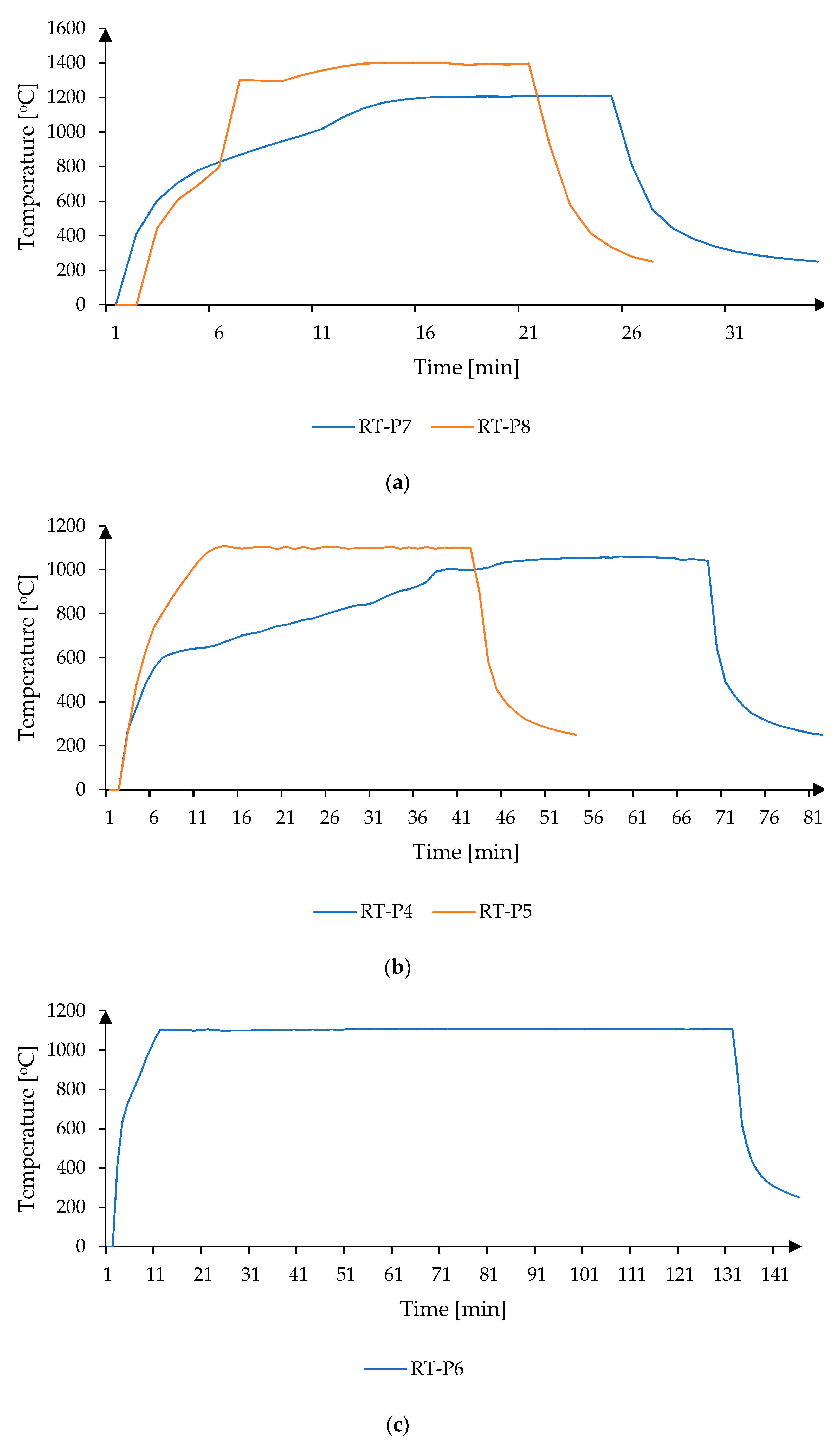
| RT-P4 | 1320 | 30 |
| RT-P5 | 1200 | 30 |
| RT-P6 | 1140 | 120 |
| RT-P7 | 1560 | 10 |
| RT-P8 | 1200 | 10 |
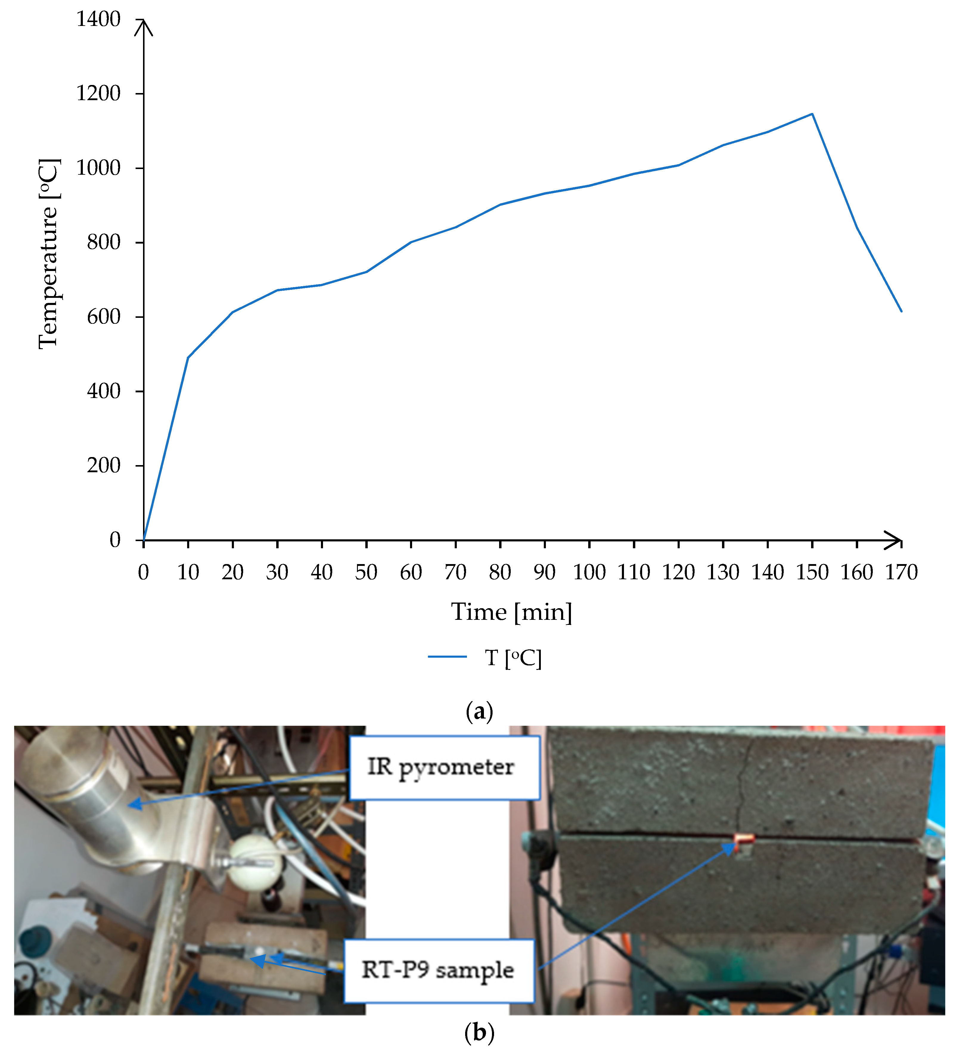
| Point | HV 1000 (RT-P8) | HV 1000 (RT-P9) |
|---|---|---|
| 1 | 450 | 740 |
| 2 | 517 | 763 |
| 3 | 665 | 780 |
| Process | Power [W] | Time [h] | Energy [Wh] |
|---|---|---|---|
| Hybrid Microwave | 3500 | 0.21 | 753.33 |
| Resistance | 4920 | 2.8 | 13,825 |
Publisher’s Note: MDPI stays neutral with regard to jurisdictional claims in published maps and institutional affiliations. |
© 2021 by the authors. Licensee MDPI, Basel, Switzerland. This article is an open access article distributed under the terms and conditions of the Creative Commons Attribution (CC BY) license (https://creativecommons.org/licenses/by/4.0/).
Share and Cite
Savu, S.V.; Tarnita, D.; Benga, G.C.; Dumitru, I.; Stefan, I.; Craciunoiu, N.; Olei, A.B.; Savu, I.D. Microwave Technology Using Low Energy Concentrated Beam for Processing of Solid Waste Materials from Rapana thomasiana Seashells. Energies 2021, 14, 6780. https://doi.org/10.3390/en14206780
Savu SV, Tarnita D, Benga GC, Dumitru I, Stefan I, Craciunoiu N, Olei AB, Savu ID. Microwave Technology Using Low Energy Concentrated Beam for Processing of Solid Waste Materials from Rapana thomasiana Seashells. Energies. 2021; 14(20):6780. https://doi.org/10.3390/en14206780
Chicago/Turabian StyleSavu, Sorin Vasile, Daniela Tarnita, Gabriel Constantin Benga, Ilie Dumitru, Iulian Stefan, Nicolae Craciunoiu, Adrian Bebe Olei, and Ionel Danut Savu. 2021. "Microwave Technology Using Low Energy Concentrated Beam for Processing of Solid Waste Materials from Rapana thomasiana Seashells" Energies 14, no. 20: 6780. https://doi.org/10.3390/en14206780
APA StyleSavu, S. V., Tarnita, D., Benga, G. C., Dumitru, I., Stefan, I., Craciunoiu, N., Olei, A. B., & Savu, I. D. (2021). Microwave Technology Using Low Energy Concentrated Beam for Processing of Solid Waste Materials from Rapana thomasiana Seashells. Energies, 14(20), 6780. https://doi.org/10.3390/en14206780