
Failure Analysis of Wind Turbine Planetary Gear


Abstract
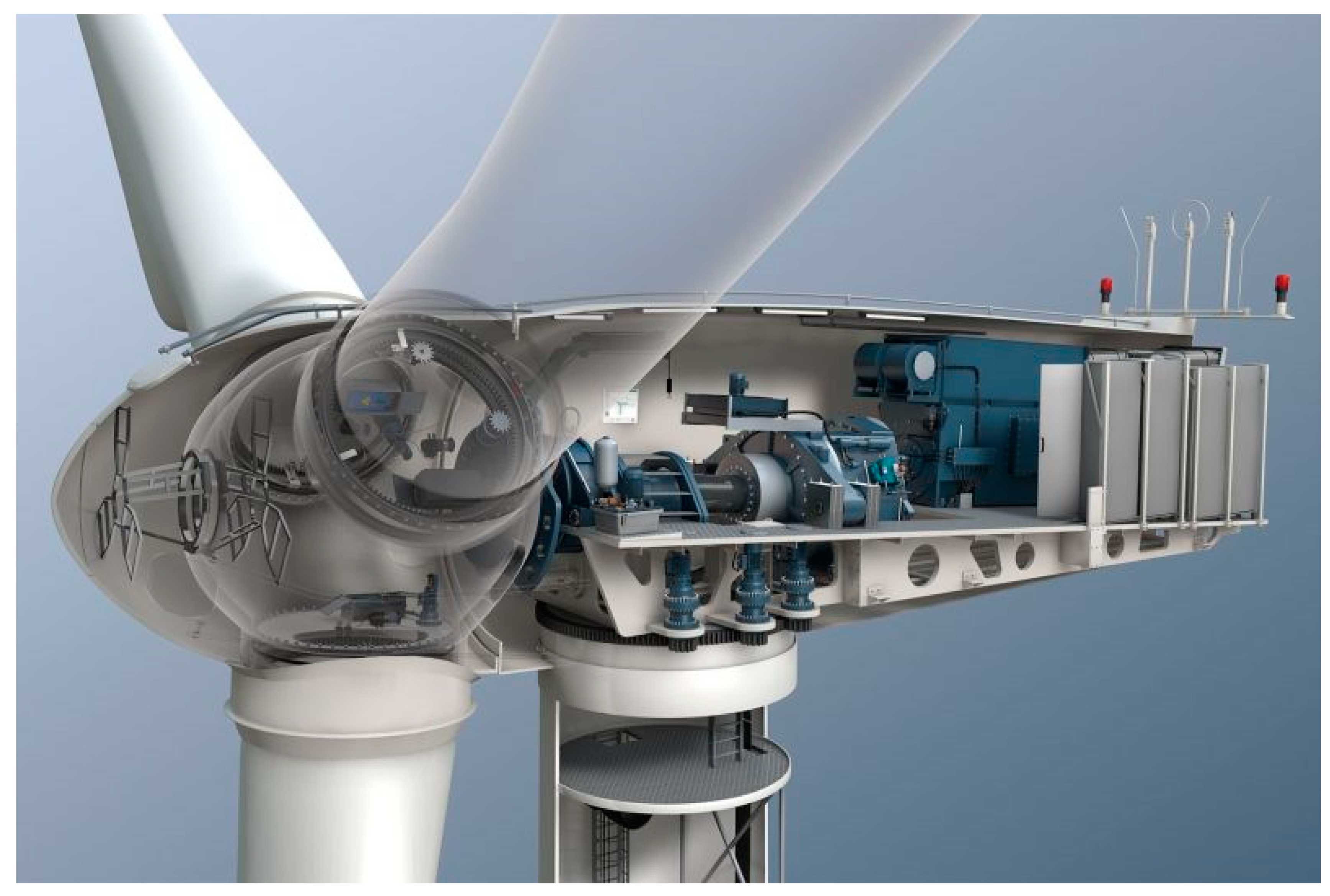
:1. Introduction
2. Development Trends in Wind Turbine Construction Elements
- Reduction of the turbine structure/weight;
- New drivetrain to eliminate or reduce the size of gearboxes;
- Turbine load analysis and mitigation, considering the dynamic coupling between translational (surge, sway, and heave), rotational (roll, pitch, and yaw) loading and turbine motions, as well as the dynamic characteristics of mooring lines for floating systems;
- Turbine and rotor designs to increase the efficiency and reliability and reduce weight;
- New generators and power electronics to increase the efficiency and reliability;
- Improving wind farm performance, considering interactions between wind turbines and also wind farms (e.g., improved wake models);
- Advanced maintenance strategies, remote monitoring, diagnostics, prognosis and health-monitoring systems, for improving reliability, reducing turbine down time, and operation and maintenance costs;
- Economic modelling and optimization of the overall wind farm system.
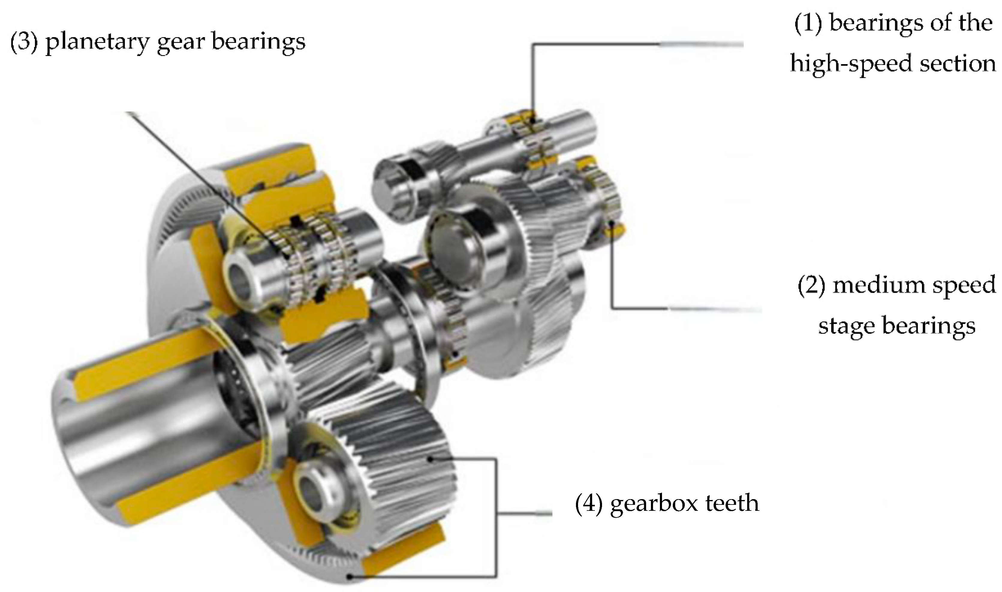
3. Operational Problems of Selected Wind Turbine Modules (Mechanisms Causing Damage to Toothed Wheels in Gearbox)
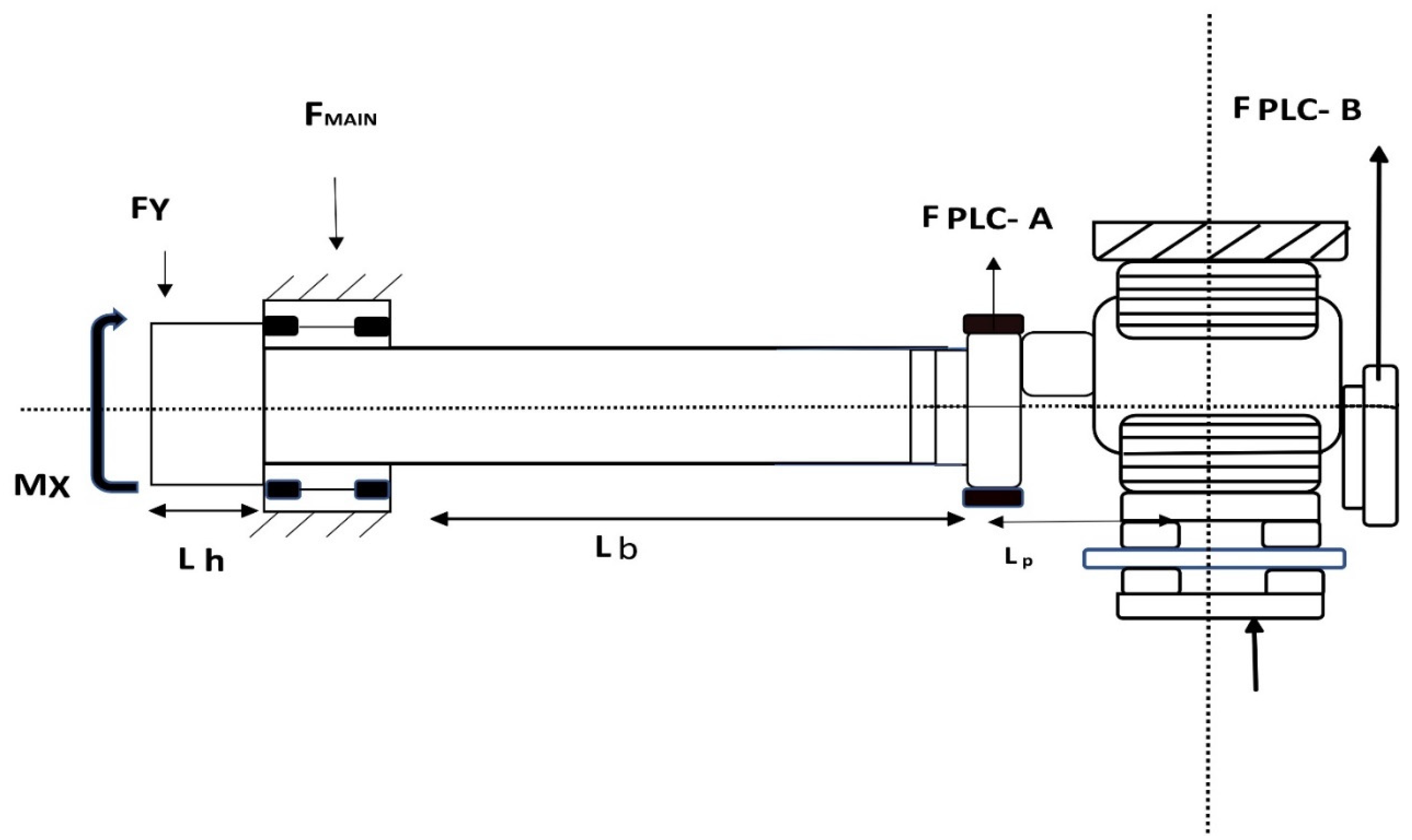
3.1. The Forces Acting on the Gear Wheels of the Planetary Gear
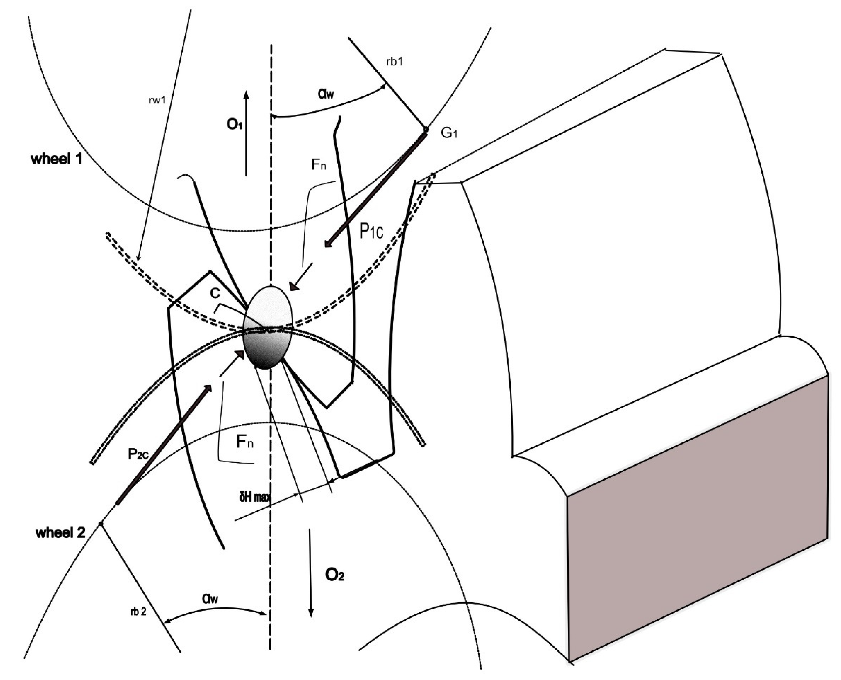
3.2. The Distribution of Forces Acting in the Mating Gear Wheels System
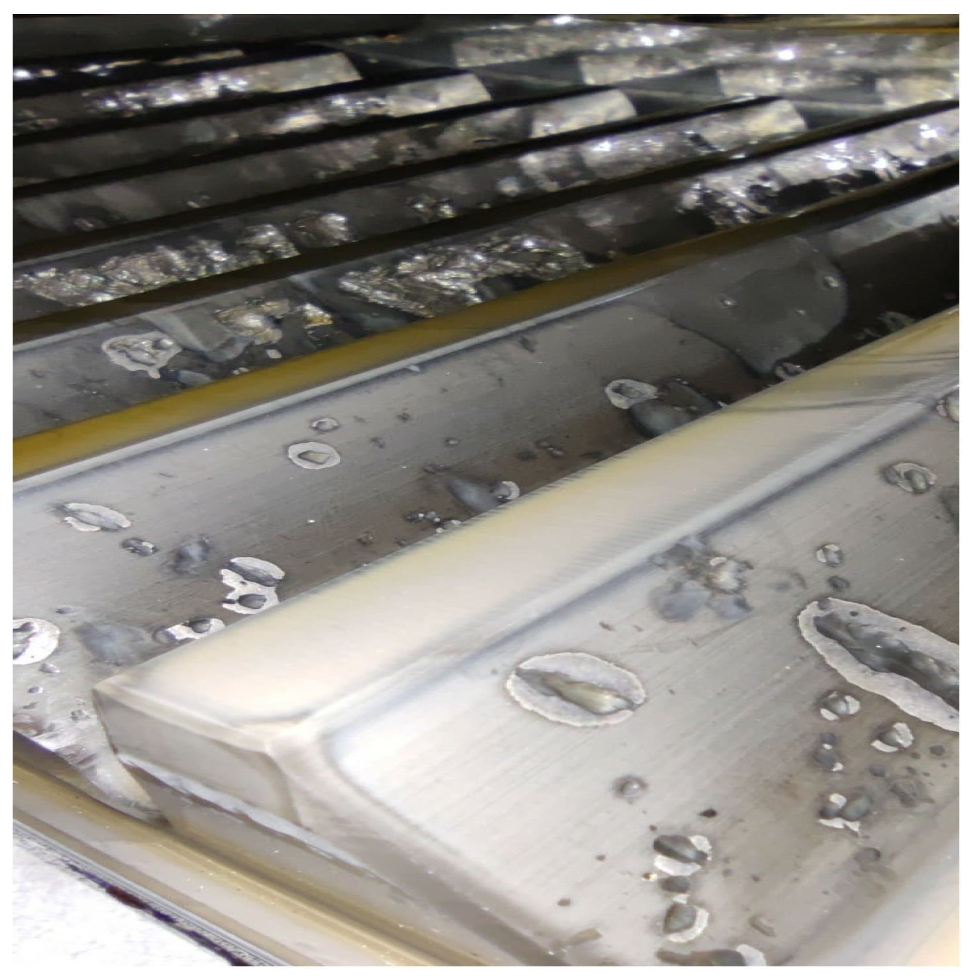
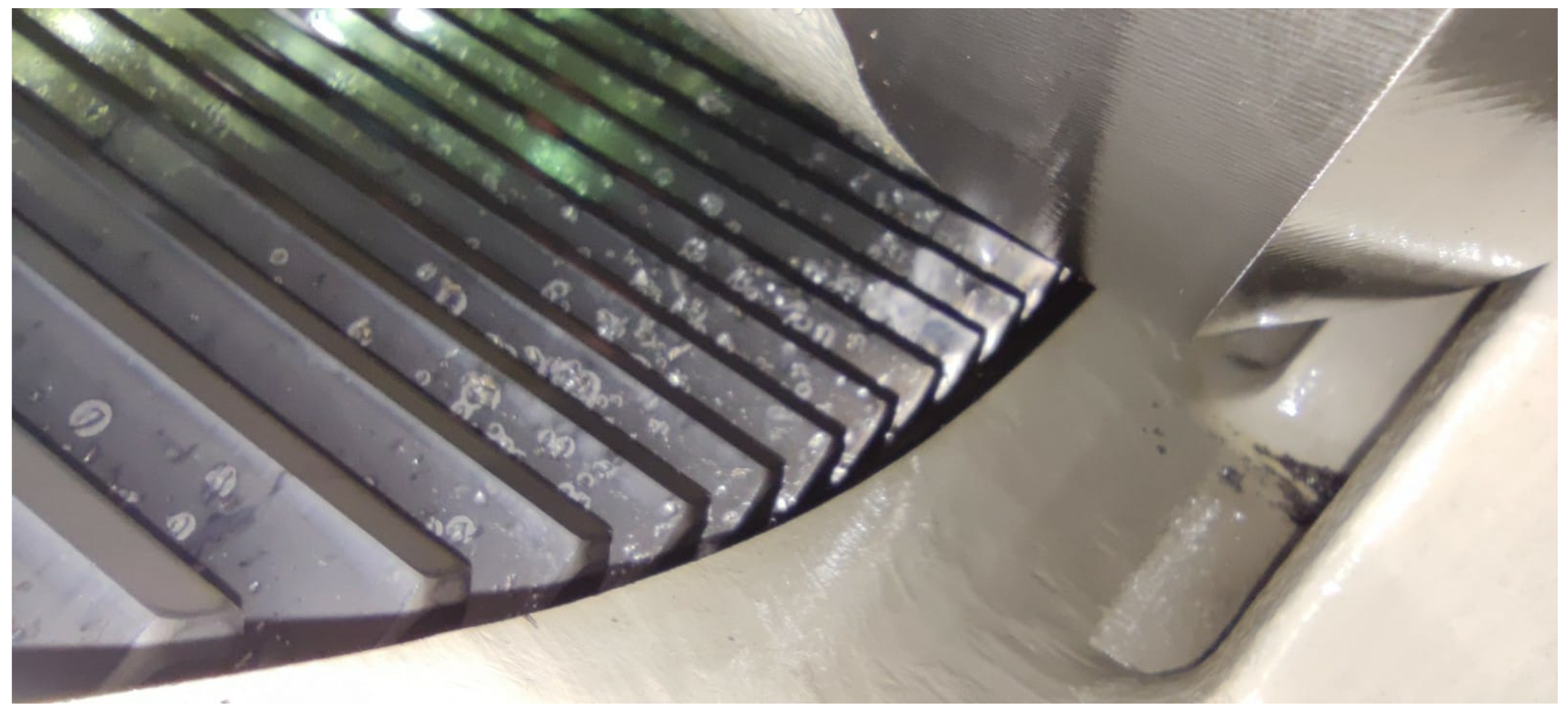
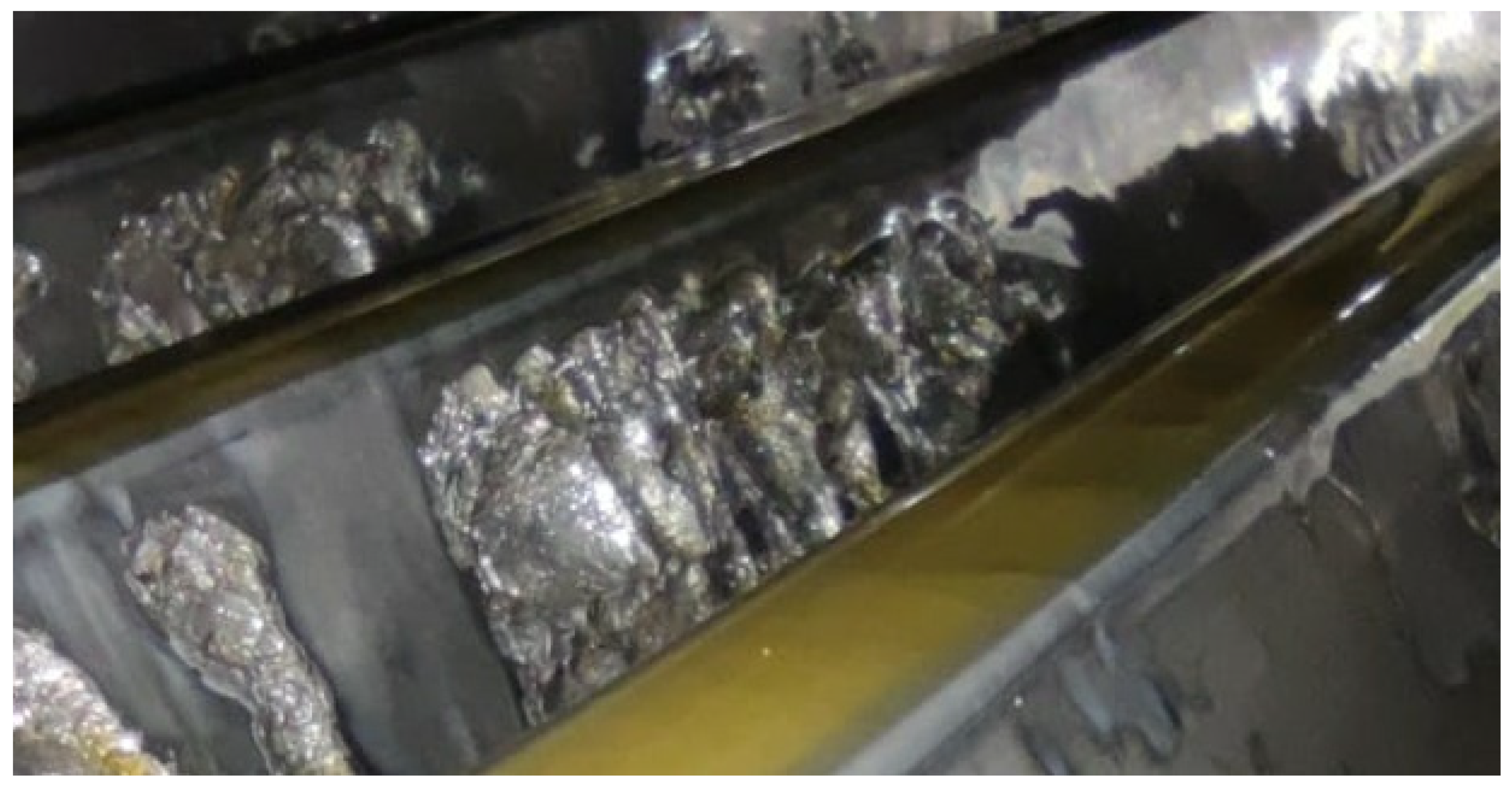
3.3. Fatigue Wear Mechanism in Gear Wheels
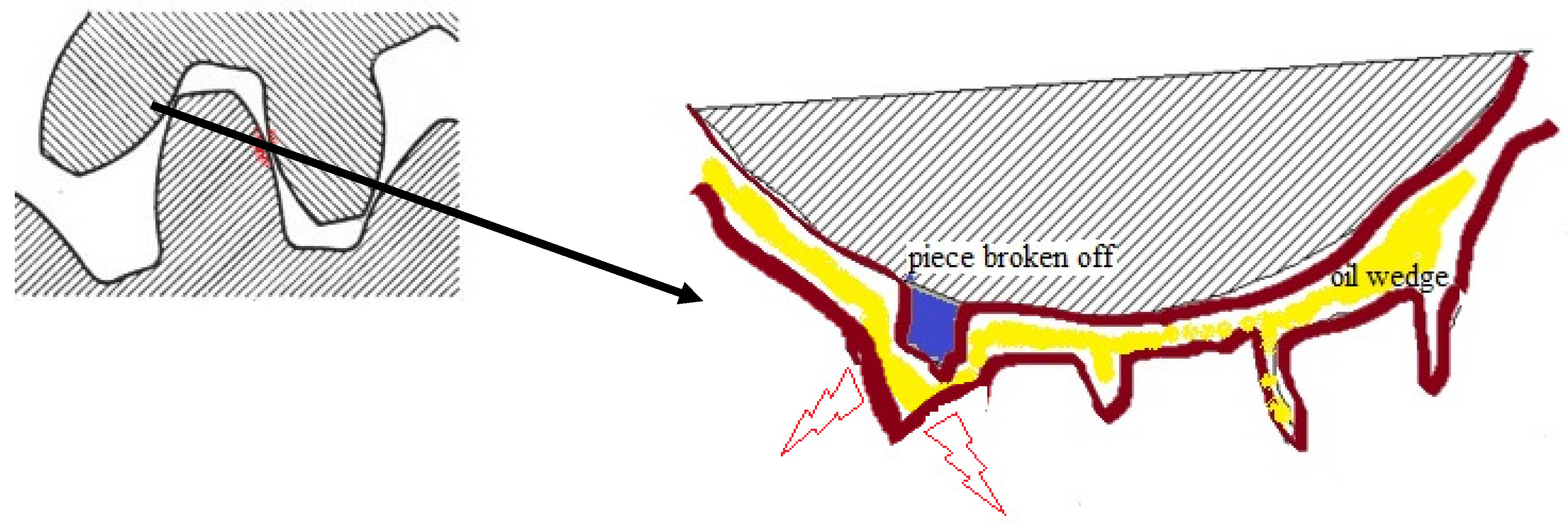
- Creation of microgaps due to fatigue of the material and propagation of cracks;
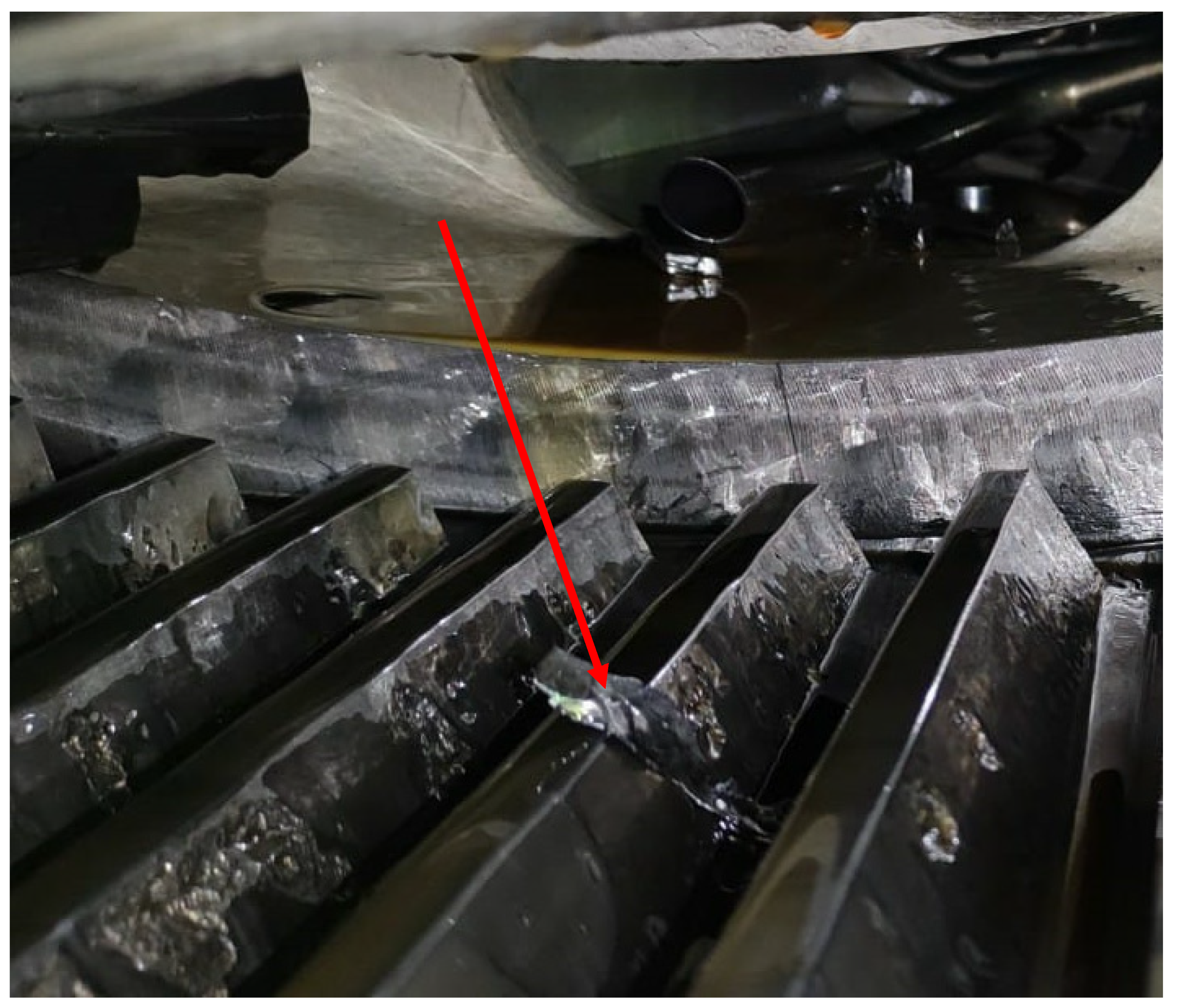
- Splitting microgaps by pressed-in lubricant during the rolling contact of teeth (growth and propagation of cracks is due to the oil wedge effect)—Figure 8;
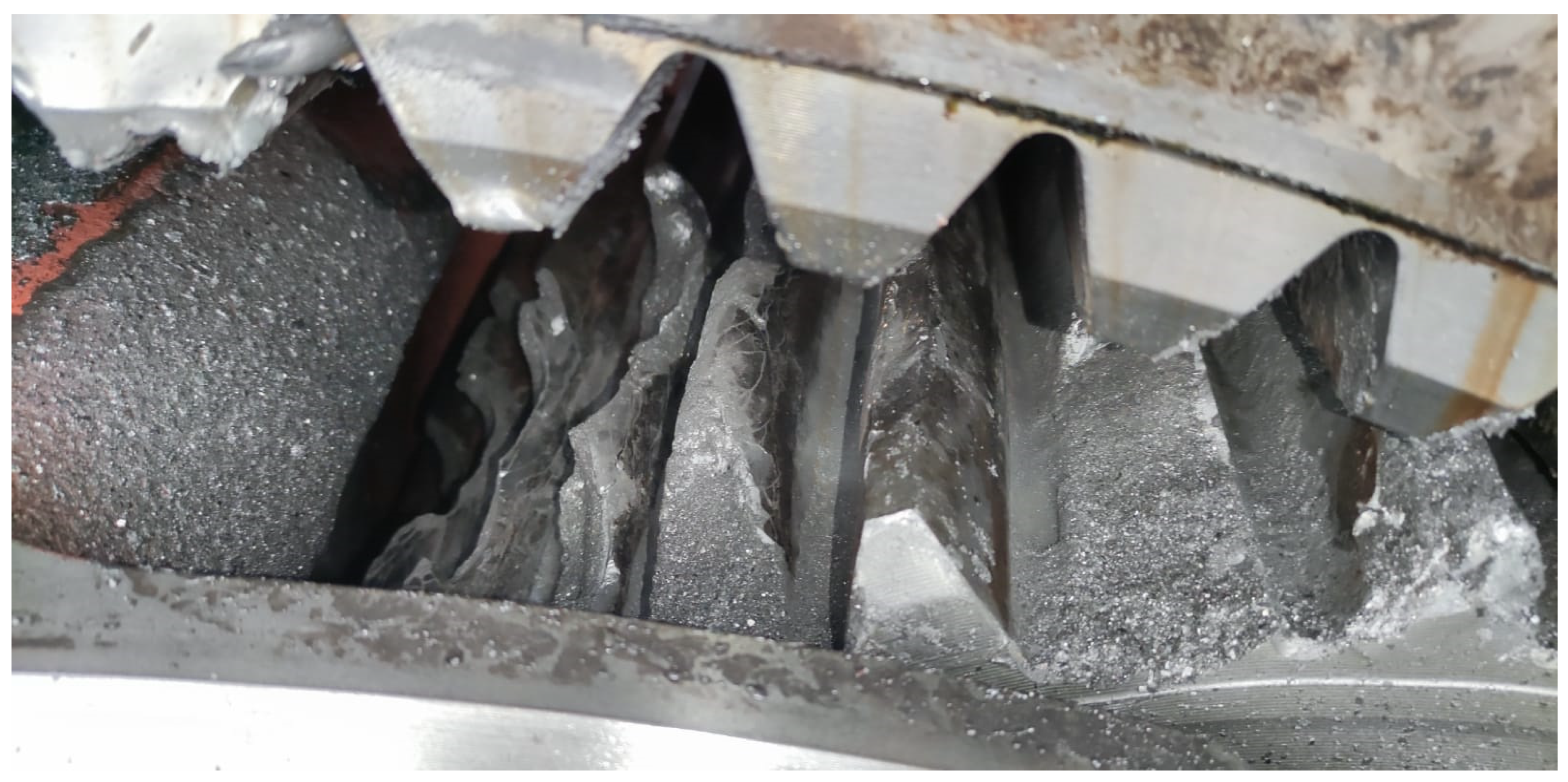
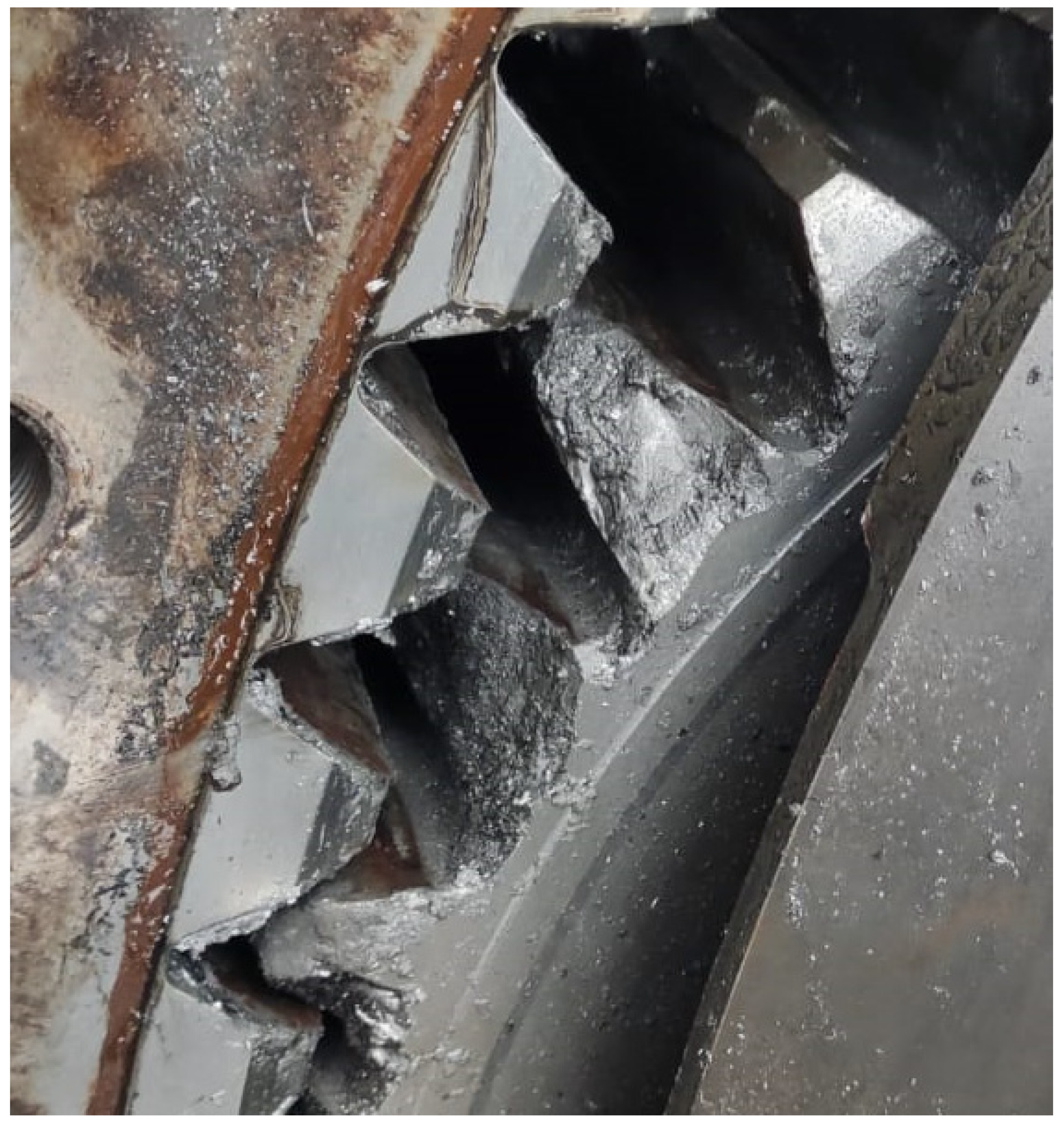
- Breaking off material particles from the surface layer (oil breaks off particles of metal which weakened or lost cohesion with the native material)—Figure 9.
4. Conclusions
Highlights
- Observations of actual gear damage allow us to conclude that there is no single rule determining the probability of gear wear rate;
- The authors indicate that it is necessary to identify the sources and analyze the gases emitted in the gear wheels region;
- Oxygen depolarization may occur on the surface of mating gears in a wind turbine, which is the cause of corrosion “foci”;
- If we assume that the first symptoms of gear wear appear under the influence of environmental and corrosive factors, and that they reveal themselves particularly early in the presence of current flow (corrosion cell), it is likely that the time of their occurrence depends on the frequency and value of stray currents in the gearbox;
- The occurrence of stray currents does not directly lead to electrical failures, but can have a significant impact on accelerating the wear process of wind turbine gearboxes—they are the cause of fatigue corrosion.
Author Contributions
Funding
Institutional Review Board Statement
Informed Consent Statement
Data Availability Statement
Conflicts of Interest
Abbreviations
| PLC-A and PLC-B | the radial forces of the main bearing |
| PL-A and PL-B | the radial forces of the planetary bearings |
| σ | stress |
| ρ | radiuses of the curvature |
| αw | angle of the contour |
| εα | transverse contact ratio |
| Fn | peripheral force |
| ZE | material coefficient accounting for the properties of the mating wheels materials |
| v | Poisson number |
| E | Young modulus |
| ZB and ZD | coefficients of one-pair tooth point pressure at the inner point B of the one-pair pinion tooth pressure or the inner point D of the one-pair wheel tooth pressure, respectively |
| ZH | the coefficient of the contact zone |
References
- Santoso, S.; Wayne Beaty, H. Standard Handbook for Electrical Engineers, 17th ed.; McGraw-Hill Education: New York, NY, USA, 2018. [Google Scholar]
- Santos, F.P.; Teixeira, A.P.; Guedes Soares, C. Review of wind turbine accident and failure data. In Renewable Energies Offshore; Guedes Soares, C., Ed.; Taylor & Francis Group: London, UK, 2015; pp. 953–959. [Google Scholar]
- Reder, M.D.; Gonzalez, E.; Melero, J.J. Wind turbine failure, tackling critical problems in failure data analysis. J. Phys. Conf. Ser. 2016, 753, 072027. [Google Scholar] [CrossRef]
- Spinato, F.; Tavner, P.J.; van Bussel, G.J.W.; Koutoulakos, E. Reliability of wind turbine subassemblies. IET Renew. Power Gener. 2009, 3, 387–401. [Google Scholar] [CrossRef] [Green Version]
- Sheng, S. Report on Wind Turbine Subsystem Reliability–A Survey of Various Databases; National Renewable Energy Laboratory (NREL): Golden, CO, USA, 2013.
- Liu, J. Research on Fault Diagnosis System of Gearbox in Large Wind Turbines. Master’s Thesis, University of Technology of Guangdong, Guangzhou, China, 2013. [Google Scholar]
- Bhardwaj, U.; Teixeira, A.P.; Guests, C. Reliability prediction of an offshore wind turbine gearbox. Renew. Energy 2019, 141, 693–706. [Google Scholar] [CrossRef]
- Dąbrowski, D.; Natarajan, A. Assessment of Gearbox Operational Loads and Reliability under High Mean Wind Speeds. Energy Procedia 2015, 80, 28–46. [Google Scholar] [CrossRef] [Green Version]
- Yan, X.; Liu, Y.; Xu, Y.; Jia, M. Multichannel failure of wind turbine driving a system using multivariate special component design and implemented Kolmogorov complex. Renew. Energy 2021, 170, 724–748. [Google Scholar] [CrossRef]
- Schubel, P.J.; Crossley, R.J.; Boateng, E.K.G.; Hutchinson, J.R. Review of structural health and spare monitoring technique for larges wind turbine blends. Renew. Energy 2013, 51, 113–123. [Google Scholar] [CrossRef]
- Huang, S.; Qi, Q.; Zhai, S.; Liu, W.; Liu, J. Seismic behavior analysis of a wind turbine supply has been verified by a sea by a series on a amplified model. Lat. USA J. Solids Struct. 2020, 17, e294. [Google Scholar] [CrossRef]
- Wang, T.; Han, Q.; Chu, F.; Feng, Z. Vibration based condition monitoring and fault diagnosis of wind turbine planetary gearbox: A review. Mech. Syst. Signal Process. 2019, 126, 662–685. [Google Scholar] [CrossRef]
- Sawant, M.; Thakare, S.; Rao, A.P.; Feijóo-Lorenzo, A.E.; Bokde, N.D. A Review on State-of-the-Art Reviews in Wind-Turbine- and Wind-Farm-Related Topics. Energies 2021, 14, 2041. [Google Scholar] [CrossRef]
- Mandal, S.K. Selection and Application of Steel: Role of Quality, Cost and Failure Analysis. In Steel Metallurgy: Properties, Specifications and Applications; McGraw-Hill Education: New York, NY, USA, 2015. [Google Scholar]
- Through Wind Energy to Energy Transformation. Available online: https://www.ifm.com/pl/pl/applications/060/poprzez-energetyk%C4%99-wiatrow%C4%85-do-transformacji-energetycznej.html#!/content/documents/pl/shared/applications/060/1020/turbina-wiatrowa-z-przek%C5%82adni%C4%85 (accessed on 1 October 2021). (In Polish).
- Bejger, A.; Gawdzinska, K. An attempt to use the coherence function for testing the structure of saturated composite castings. Metalurgija 2015, 54, 361–364. [Google Scholar]
- Qian, Y.; Yan, R. Gearbox Fault Diagnosis in a Wind Turbine Using Single Sensor Based Blind Source Separation. J. Sens. 2016, 2016, 6971952. [Google Scholar] [CrossRef] [Green Version]
- Lei, Y.; Lin, J.; Zuo, M.J.; He, Z. Condition monitoring and fault diagnosis of planetary gearboxes: A review. Measurement 2014, 48, 292–305. [Google Scholar] [CrossRef]
- Inspection of Gears in Wind Turbines. Available online: https://www.olympus-ims.com/pl/applications/rvi-wind-turbine/ (accessed on 1 October 2021). (In Polish).
- Zhang, C.; Wei, J.; Wang, F.; Hou, S.; Zhang, A.; Lim, T.C. Dynamic model and load sharing performance of planetary gear system with journal bearing. Mech. Mach. Theory 2020, 151, 103898. [Google Scholar] [CrossRef]
- Wang, C.; Parker, R.G. Modal properties and parametrically excited vibrations of spinning epicyclic/planetary gears with a deformable ring. J. Sound Vib. 2021, 494, 115828. [Google Scholar] [CrossRef]
- Kahnamouei, J.T.; Yang, J. Development and verification of a computationally efficient stochastically linearized planetary gear train model with ring elasticity. Mech. Mach. Theory 2021, 155, 104061. [Google Scholar] [CrossRef]


Publisher’s Note: MDPI stays neutral with regard to jurisdictional claims in published maps and institutional affiliations. |
© 2021 by the authors. Licensee MDPI, Basel, Switzerland. This article is an open access article distributed under the terms and conditions of the Creative Commons Attribution (CC BY) license (https://creativecommons.org/licenses/by/4.0/).
Share and Cite
Bejger, A.; Frank, E.; Bartoszko, P. Failure Analysis of Wind Turbine Planetary Gear. Energies 2021, 14, 6768. https://doi.org/10.3390/en14206768
Bejger A, Frank E, Bartoszko P. Failure Analysis of Wind Turbine Planetary Gear. Energies. 2021; 14(20):6768. https://doi.org/10.3390/en14206768
Chicago/Turabian StyleBejger, Artur, Ewelina Frank, and Przemysław Bartoszko. 2021. "Failure Analysis of Wind Turbine Planetary Gear" Energies 14, no. 20: 6768. https://doi.org/10.3390/en14206768
APA StyleBejger, A., Frank, E., & Bartoszko, P. (2021). Failure Analysis of Wind Turbine Planetary Gear. Energies, 14(20), 6768. https://doi.org/10.3390/en14206768