1. Introduction
The driver-operated steering system is the basic equipment of the modern car and will remain so for a long time, despite the introduction of autonomous vehicle technology. According to the SAE classification (level of steering automation [
1]), from L1 to L3 or even partially L4, the steering system will remain an element used by drivers. Persons with reduced mobility require a special adjustment of this system to the individual characteristics of their disability. This adjustment often requires additional, very expensive mechanical systems, thus cannot be considered for mass production. In addition, adjusting the parameters of the steering system to the individual characteristics of a fully able-bodied driver in modern cars is very limited and comes down to the tilt of the steering wheel or, by adjusting the seat, to changing the driver’s distance from the steering wheel. The approach presented by the authors is based on universal design but complemented with additional individual adjustment of the steering system to specific users. The definition of “universal design” is included in the Convention on the Rights of Persons with Disabilities [
2]: “Universal design” means the design of products, environments, programs, and services to be usable by all people, to the greatest extent possible, without the need for adaptation or specialized design. “Universal design” shall not exclude assistive devices for particular groups of persons with disabilities where this is needed. This additional help is implemented using the “custom design” methodology. If something is custom designed, it is made according to someone’s special requirements. This approach also applies to people with special needs who, depending on their limitations, have individual needs, the fulfilment of which ensures their greater independence and the ability to function in society.
A detailed analysis of the division into a group of able-bodied and disabled people does not give a clear answer as to the border between these groups. This border is blurred. Do we, for example, include the elderly with a number of age-related ailments in the group of disabled or nondisabled people? Failure to answer this question requires a special approach to the design of control devices used in vehicles. Speaking about universal design of the steering system, the authors require one basic condition to be met at the beginning, namely equipping the vehicle with a “steer by wire” system, i.e., the one that does not have a mechanical position between the steering wheel and the steering system [
3]. The “steer by wire” technology was initially introduced in aviation (in particular when piloting large passenger jets), due to the high physical effort required from pilots using classic solutions of control devices. In the automotive industry, according to the authors, it is an indispensable solution in the universal design methodology. The elements of the steering system that should be subject to universal design and elements that should be additionally adapted to the individual characteristics of the driver with the use of “custom design” are defined below. They are divided into parametric and structural factors. In addition to classic adjustments (e.g., tilting the steering wheel, adjusting the driver’s position in relation to the steering system by changing the position of the seat), the following can be mentioned:
- (a)
Parametric factors
Gear ratio of the steering system:
The resistance of the steering element (steering wheel or, e.g., joystick lever) during the maneuver (so-called “force feedback” [
4]).
The parameters of the damping filter, e.g., vibrations of the driver’s hands.
Geometric dimensions of the steering element.
- (b)
Structural factors
Constructional solution for the steering system (steering wheel, multifunction steering wheel, joystick, sensor) for cooperation with bionic systems (e.g., bionic prosthesis after limb amputation).
The abovementioned systems must be consistent in the IT sense, e.g., integrated in the CAN bus. The steering system control calculations in the “steer by wire” technology should be performed by the host computer. The cost of adjusting the parametric and structural factors is relatively low. The question arises of how to verify the correct functioning of individual factors, and how to take into account the preferences of drivers. Correctness is understood as safety and comfort (as defined by drivers) in performing individual maneuvers. In the article, the authors do not analyze the problem of the reliability of operation of individual systems. It is a separate problem playing an important role in the “steer by wire” solutions, in particular in the automotive industry [
5]. A separate problem, discussed in the article, is the training of drivers and verification of their skills. The article proposes a methodology for evaluating the functionality of new solutions consisting, inter alia, in:
Use of dynamic vehicle simulators for conducting research.
Analysis of the correctness of performing maneuvers.
Performing an EMG measurement (surface electromyography) to analyze muscle activity and possible fatigue).
Drivers’ surveys.
The implementation of automated driving as well as of new interface solutions requires adequate training and, before that, an appropriate choice adequate to the driver’s needs. A consequence of the changes in interface design will be the need for a selection and certification procedure for new equipment. The increasing level of automation in transport also foresees additional training for drivers to verify their, sometimes completely new, skills necessary when using nonstandard solutions. The authors propose their vision of a procedure for implementing new steering system designs, which defines the necessary conditions that must be met before a given solution is implemented in individual vehicles.
2. Materials and Methods
The main aim of the experiment was an attempt to introduce correctness measures for maneuvers performed with the use of a multifunction steering wheel and to propose an evaluation of the biomechanical factors of the driver through the use of the electromyography (EMG) [
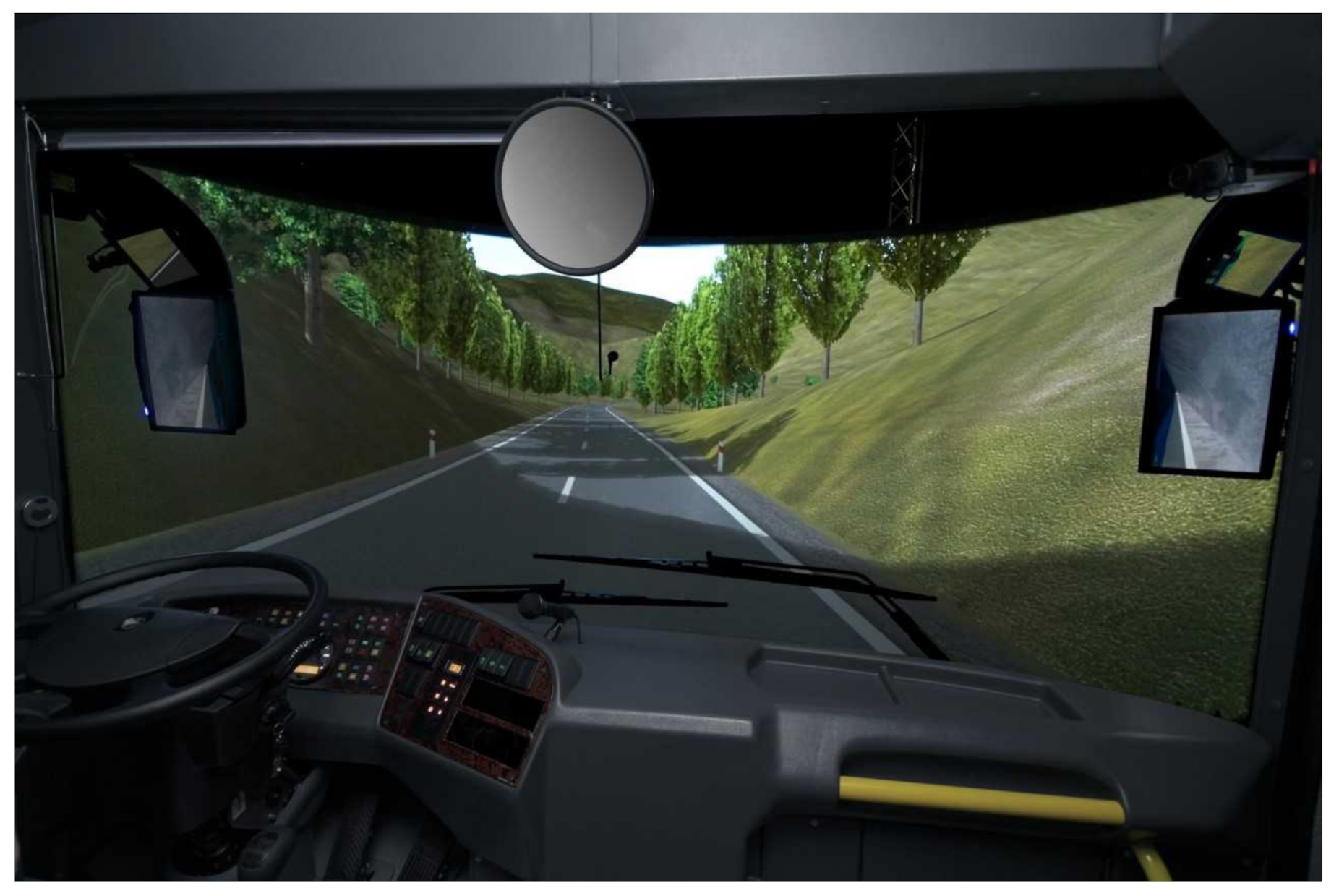
6] measurement. The tests were carried out in a dynamic physical simulator by Aerospace Industries (
Figure 1). Partial results of these studies have been published in previous papers [
7,
8,
9].
The description of the experiment conducted by the authors includes:
2.1. Research Sample
At this stage of the research, the group of participants in the experiment was limited to able-bodied drivers. The participation of disabled drivers required the adaptation of the dynamic simulator to enable the driver’s cabin on a wheelchair to enter and exit the simulator. The study of this group of people is planned in the next stage. The research group consisted of 30 men aged 20–23. All drivers had a driving license. The second important limitation was the assumed number of test runs. Each driver performed two road tests, driving the vehicle using three steering wheels consecutively. In each test, the driver made three runs: with the classic steering system, and the ECO steering wheel with two gear ratios. In order to simplify the descriptions, in the tests in question, the following symbols were introduced: NOR (max rotation ±720°) standard steering wheel, ECO 180 steering wheel, for which the max rotation was ± 180°, and ECO 120, for which the max rotation was ±120°. The maximum turn of each steering wheel corresponded to a steering angle of the front wheels of ±35°. The participants of the experiment did not constitute a representative sample for adult Polish citizens. It was a rather simple sample. With such a small sample, striving for a high “representativeness” of the sample would be even a methodological error. The dispersion of the results would probably render the obtained results worthless (they would be characterized by a very large dispersion).
2.2. Research Object
The tests were carried out in a simulator but were related to a specific vehicle solution. The mentioned solution is an “eco-car” developed under the [
11] project (this car is shown in
Figure 2a). The design of the vehicle was based on the principles of universal design, i.e., it was assumed that it will be an electric vehicle intended for rental by drivers of various abilities, including drivers using active (hand-powered) wheelchairs. The implementation of the universal design postulated required the design of a number of solutions ensuring the required functionality of the eco-car, such as:
Lowered car floor/air suspension.
Front seat folding and sliding system.
Active wheelchair fixing system in the case of a driver with reduced mobility.
Handles facilitating entry of the wheelchair from the side.
Fold-out side steps to facilitate the entry of the wheelchair.
Driver interface–remote control + touch screen + multifunction steering wheel.
Adjustable control panel/with steering wheel and driver interface/–horizontal and vertical adjustment.
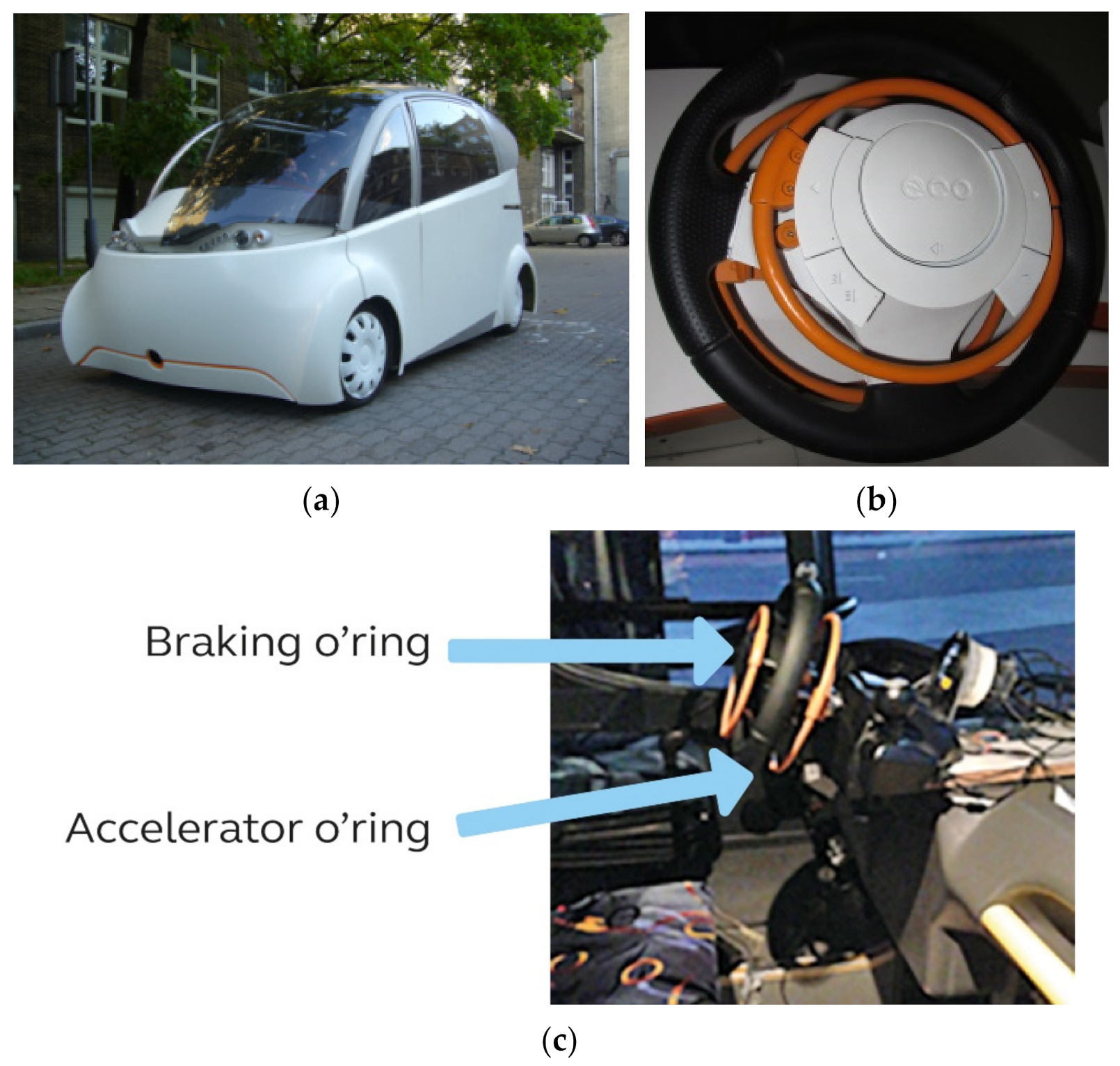
The car tested in the simulator was equipped with a designed multifunction steering wheel (see
Figure 2b) to test its functionality. The versatility of the multifunctional steering wheel consists of the fact that, although it is aimed to be used by people with limited or complete lack of lower mobility, it does not exclude the possibility of steering the vehicle by able-bodied people. The tested eco-steering prototype is characterized by the fact that the main steering activities are performed only through the upper limbs, which is possible thanks to the steer-by-wire system of the designed eco-car. Two additional rings (hereinafter the “O-rings”) that the steering wheel is equipped with are used for braking (smaller ring) and acceleration/maintaining a constant speed (larger ring). The orange color of both O-rings allows for their faster identification during use. In the case of this solution, the angle of rotation of the steering wheel was limited. People with paresis of the lower limbs often also have manual limitations of the upper limbs, in particular the hands, so in their case, limiting the range of steering wheel rotation may facilitate steering. Taking this into account, the steering gear ratio has been programmatically limited to a rotation angle of 180 or 120 degrees per full turn of the car’s front wheels. In addition to O-rings, the steering wheel is equipped with function buttons located on its rim, which are operated without taking hands off the steering wheel. The vehicle with the said steering wheel was recreated in a dynamic simulator of motor vehicles.
2.3. Research Methodology
2.3.1. Simulator Research
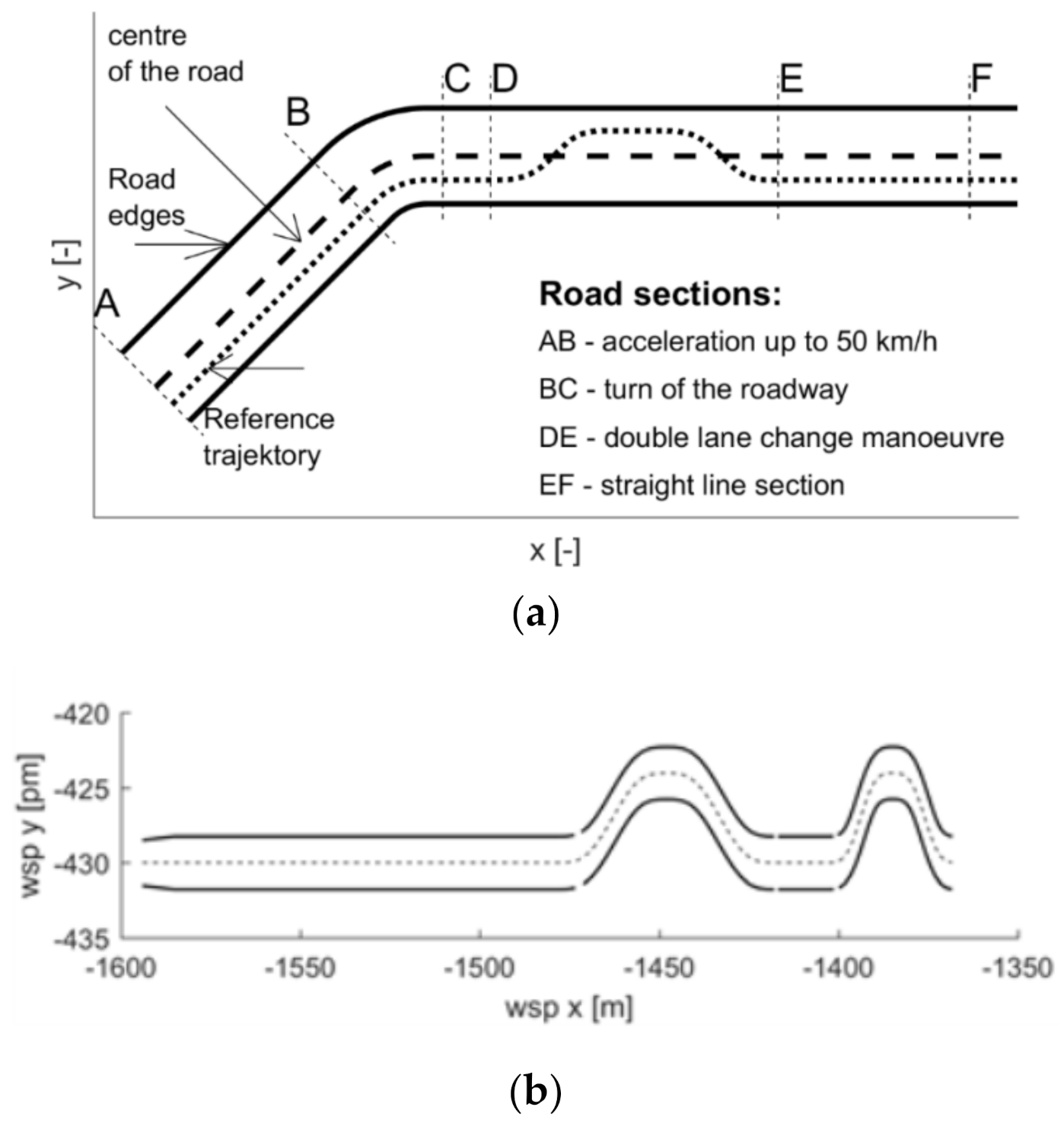
The simulator tests concerned the analysis of two cases: the “route” type ride, shown in
Figure 3a [
7], and the “slalom” type ride, shown in
Figure 3b [
8].
The “route” type ride consisted of straight sections connected by a circular curve (
Figure 3a). The recording of the experiment began after reaching the speed of 50 km/h. In the second straight section, the driver had to maneuver around the obstacle (typical for the “moose” test). The “slalom” ride required a simultaneous change in speed and direction of driving, as shown in
Figure 3b. In the first case, the driver’s task was to follow the centerline of the lane; in the second, to follow the reference space-time line, i.e., the driver had to change speed in line with the reference space–time line (this required intensive use of acceleration and braking O-rings). Each of the tested drivers performed four runs: one training run and three runs with a steering wheel of the NOR type (the gear ratio in a typical car: two and a half turns of the steering wheel correspond to a turn of the wheels by approx. ±35 degrees), one with an ECO 180 steering wheel (the ratio of 180 degrees of the steering wheel rotation corresponds to approx. ±35 degrees of the wheels rotation), and the ECO 120 steering wheel (the ratio of 120 degrees of steering wheel rotation–approx. ±35 degrees of the wheels’ rotation). The influence of the gear ratio on the “driving accuracy” was analyzed. The simulator screen is shown in
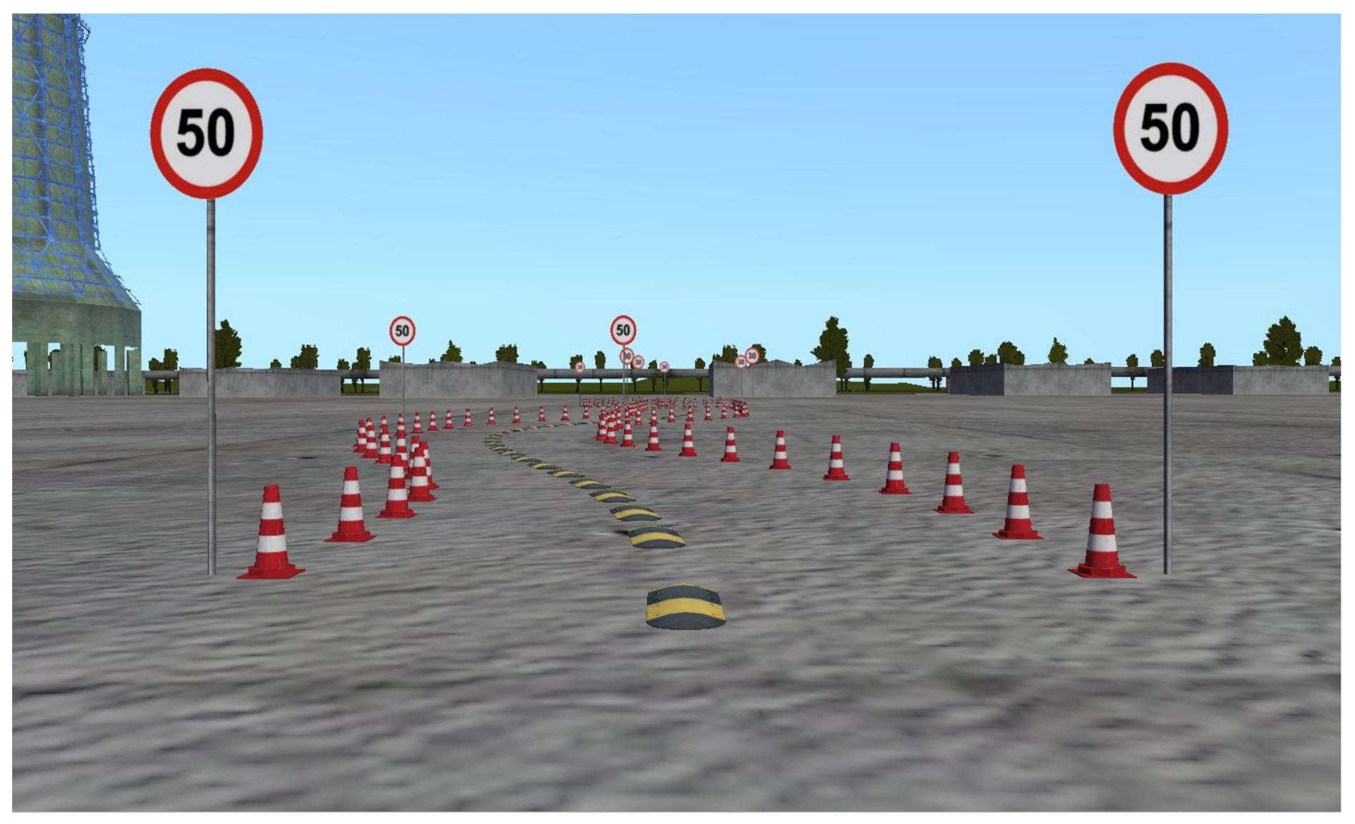
Figure 4.
Defining the driving evaluation criteria was essential. Three criteria (measures) were used here: the first: the technical one, the second: the biomedical nature one based on the EMG measurement, and the third: based on the assessment of the experiment participants’ survey.
The measurements for a maneuver’s correctness were:
where
T is the duration of the experiment, 5000 (s);
Λ is route length;
s is deviation from the lane centerline measured along the normal to the curve.
where T is the duration of the experiment, 5000 (s); deltaV is deviation from the set speed.
The EMG analysis procedure was based on the signal obtained as a result of the applied surface electromyography.
2.3.2. Upper Limb Muscle Load Tests (EMG)
Noraxon [
12] apparatus was used to measure the electromyography signal. The EMG signal was recorded with the use of surface electrodes. This signal, which gives a picture of muscle activity, is strongly dependent on internal (individual factors) and external [
13] factors. So, it is not a signal with constant parameters (such as body temperature). Internal factors include conduction velocity of muscle fibers, thickness of the subcutaneous layer (fat content), and the proportions of a specific type of muscle fibers. External factors are related to the type of measuring electrodes used and the electrical resistance between the electrode and the skin. Moreover, the EMG signal depends on the geometric factors influencing the change in the length of the muscle (here: resulting from the change of body position and the technique of driving on the tested device). Among the factors influencing the EMG signal, the physical activity of the tested persons should also be specified. The analysis of the results of the experimental tests was carried out based on the most frequently used parameters of the EMG signal. These parameters are determined with respect to time (RMS amplitude) and frequency (MPF average frequency, determined following the Fourier transform).
The first type of analysis was used in the study because the EMG signal amplitude is an important indicator of muscle activity. The analysis of the EMG signal amplitude can be performed based on the root mean square (RMS) amplitude. The method of determining the RMS parameter is described in Relation (4). The RMS parameter is determined from signal fragments (so-called windows) of a specific length.
where
n is the number of samples to be analyzed (window length);
Xi is the value of the
i-th sample.
The basic parameters of the experiment are defined below.
Duration of the experiment: about 5000 (s).
Sampling frequency: 1500 (Hz) (more than twice the Nyquist frequency).
Transfer frequency of Noraxon apparatus equipped with an anti-aliasing filter: it is in the range of 10–500 (Hz).
Duration of the experiment was divided into one-second time intervals, i.e., 1500 samples were obtained for one interval.
In order to avoid errors, e.g., spectrum blur, the Hanning window was used for each interval.
The division into time intervals significantly influences the conditions of the analysis. In general, an EMG signal is not a stationary signal. It may show changes over the course of the experiment (e.g., a downward trend which is a measure of fatigue). It is assumed that the signal is locally stationary in the analyzed time intervals. The time intervals “overlap”, which means that the obtained parameters (in this case, RMS) in adjacent intervals are strongly correlated with each other.
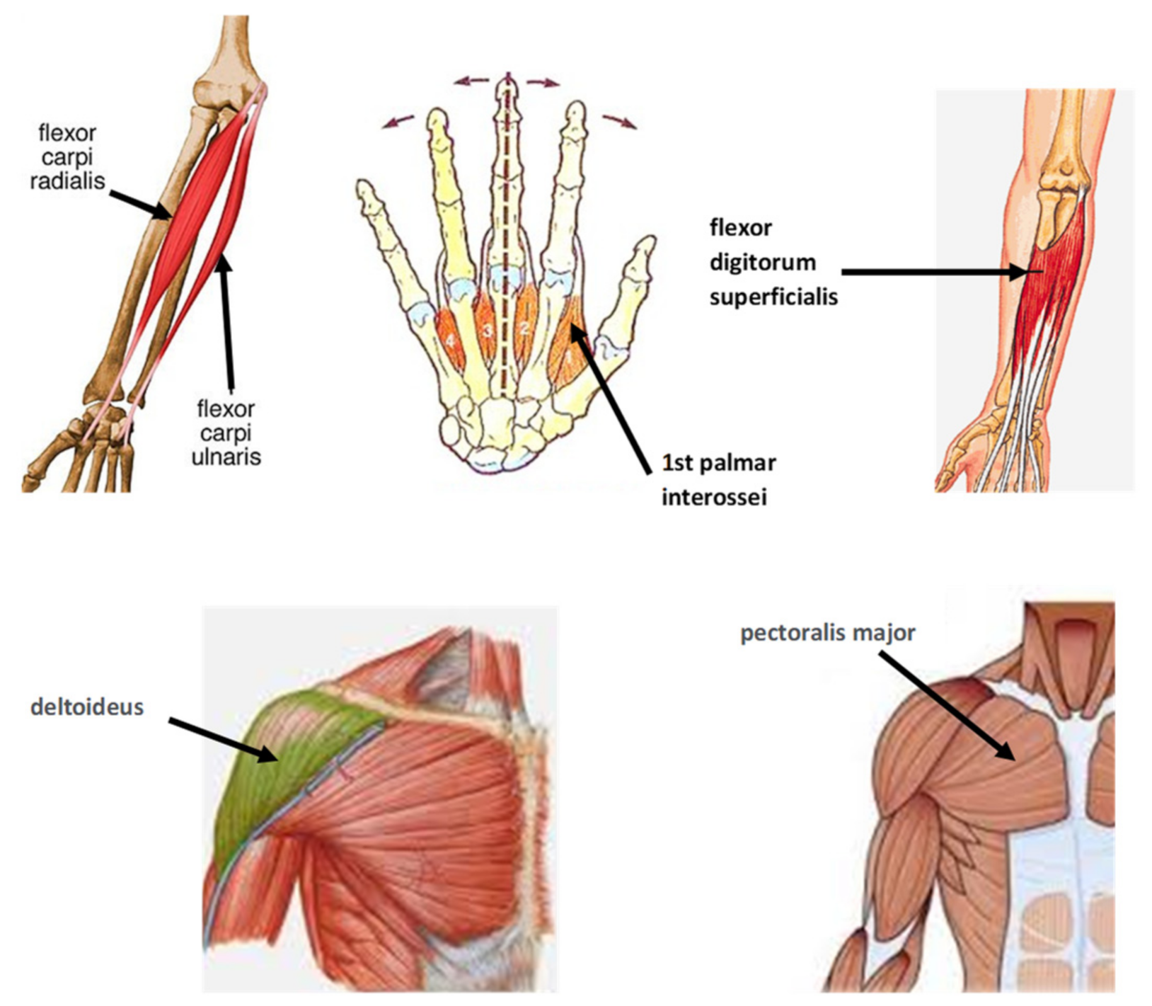
The subject of the analysis was six muscles from
Table 1. The selection of muscles was made based on the literature analysis [
14,
15,
16,
17,
18,
19,
20,
21] as well as consultations with a physiotherapist [
21].
Figure 5 shows the visualization of the muscles selected for the study.
EMG signals were measured using surface electrodes placed on the right limb of each participant, as shown in
Figure 6. The signals were recorded while performing the assumed rides (“route”, “slalom”).
The obtained “raw” EMG results needed to be normalized. The most common method, known as MVC normalization, refers to the maximum voluntary contraction (Xmax; shown in
Table 1) prior to starting the test measurements. Typically, MVC contractions are performed against static resistance. Ordinary (untrained) participants in the experiment may have difficulty reaching the MVC level as they are not used to such an effort. For patients who cannot, and should not, perform MVC due to damaged muscle structures, other methods of processing and analysis should be considered. Ultimately, the subject of the analysis in the experiment was the signal determined by the formula:
where:
Xminimum represents EMG signal emitted at no load.
2.3.3. Evaluation of the Steering Wheel’s Functionality
At this stage of research, it was necessary to consider how to verify the functionality of the universal steering wheel. In this case, the functionality of the steering wheel is understood as its influence on driving correctness and level of muscle load. This problem should be worked out using methods of statistical analysis based on the methods of experimental research. The properties of correctness of driving with a standard steering wheel with pedals were adopted as a reference level of the functionality. It was so because this type of steering wheel is a long-time, well-established solution. However, it needs to be remembered that the standard steering wheel does not make it possible to drive a vehicle for people with disabilities of the lower limbs. Thus, it will not find its application in the eco-car. Thus, the aim was to find an answer to the question of whether the newly designed ECO steering wheels (intended for use in the eco-car) are better or worse than the standard steering wheel, in terms of the analyzed test drive quality indicators. In order to achieve this goal, the following evaluation algorithm was adopted:
Rides with the use of the defined types of steering wheels create the category of a priori event type (events determined before the measurement).
The ride quality indicators characterizing the ride quality and muscle fatigue are dependent random events (events obtained from the experiment).
The working hypothesis is the null hypothesis on the lack of dependence of the ride quality on the steering wheel type and the alternative hypothesis that such a relationship exists.
Applying the confirmatory—confirming procedure to confirm the credibility of the null hypothesis (at the assumed level of significance) or the confirmatory—rejecting procedure to establish the credibility of the alternative hypothesis (at the assumed test power).
Post hoc analysis (after the fact) to determine the value of the registered dependence (if any).
This algorithm, sketched very generally, required the use of a variety of statistical tests such as, for example, the Shapiro–Wilk test for normality, the Friedman’s test of concordance (substitute for the ANOVA test for nonparametric hypotheses), and the Wilcoxon test for the relationship of paired observations. In the case of variables dependence confirmation, a simple post hoc analysis was performed, consisting of the classification of differences in the quality indicators of paired observations.
3. The Results of the Experiment
The following graphs show the results for one tested driver. As mentioned earlier, the sample included similar people, of similar age, skills, and one gender. This was reflected in relatively small differences in the obtained results, at the level of 10%. The presented results for a specific driver are therefore representative for the entire analyzed sample.
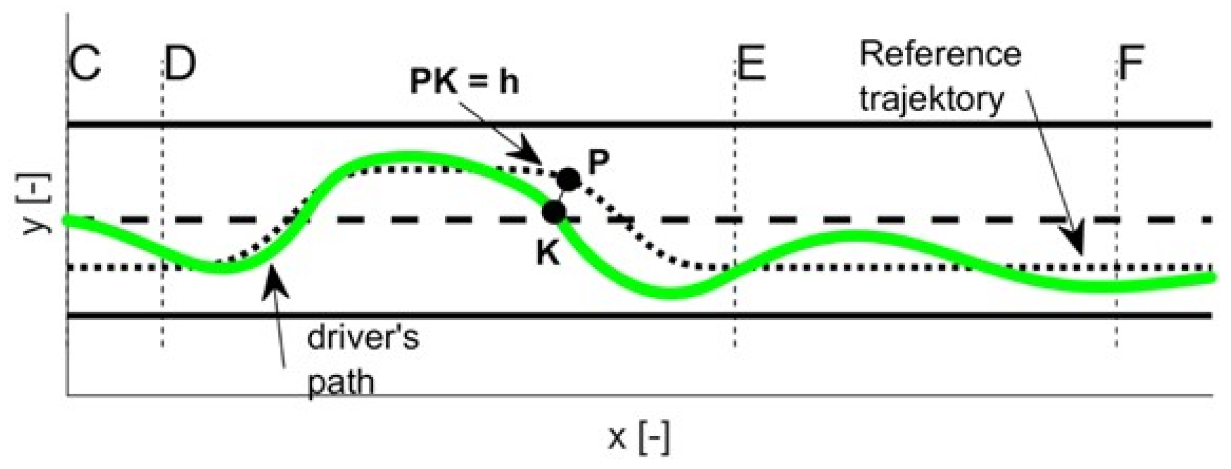
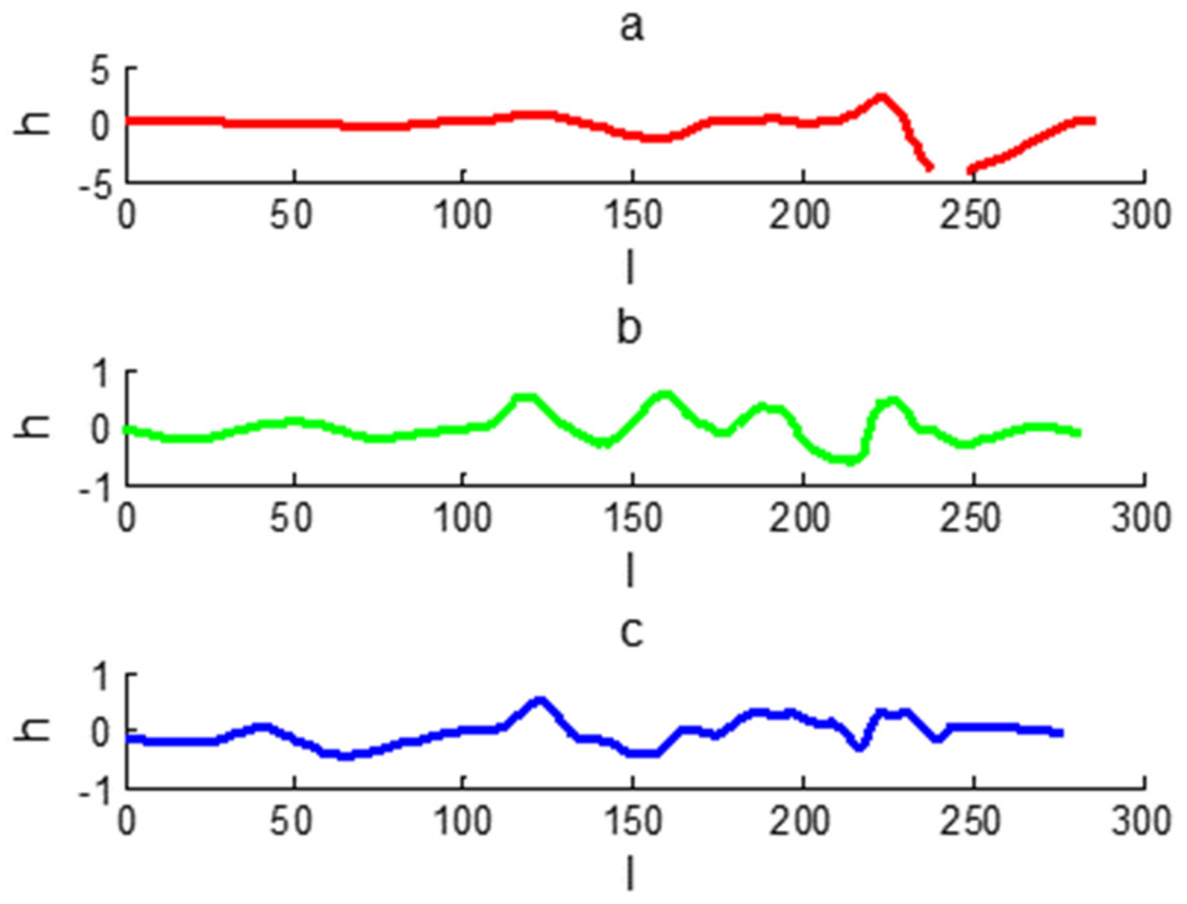
The h parameter is the RMS value calculated for time intervals (not for the entire duration of the experiment T). The physical interpretation of the h parameter is shown in
Figure 7.
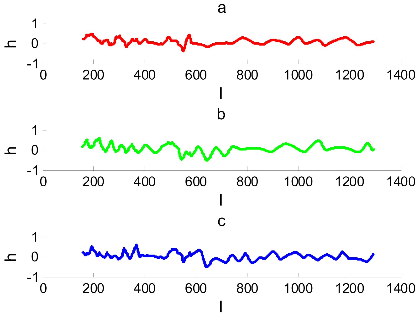
Figure 8,
Figure 9 and
Figure 10 show the course of the h parameter as a function of time for different types of steering wheels and the “route” type ride.
3.1. Analysis of the Correctness of Performing Maneuvers
The necessary condition for the ride to be considered correct (along with the maneuvers that everyone had to perform) is that the car does not leave the lane boundaries (one lane), and in the case of the moose test (“slalom” type ride), it does not leave the road (two lanes). This condition was met by all participants of the experiment. Then, the subject of detailed analysis was to determine the h deviation from the reference line.
The subject of comparative analyses in the group unit is the parameters of the characteristics of the runs made for three types of steering wheels: NOR, ECO 180, and ECO 120.
The charts relating to the “route” type ride show no particular differences. However, driving with a standard ratio steering wheel gives the smoothest ride. More sensitive steering wheels (ECO 180 and ECO 120) show a much greater “yawing” effect. The driver has more difficulty keeping the rectilinear motion. This effect is very clear and as expected. A similar effect also occurs during the “slalom” test ride. This situation is even more surprising since for more sensitive steering wheels it is reasonable to expect an increase in precision of performing a turning maneuver. However, also in this case, a deterioration of the values of the quality indicators describing the ability to follow the reference trajectory was observed. This effect may be related to the acquired habits of drivers resulting from the practice of driving cars with the standard steering wheel. It is difficult for the driver to adapt the correct angle of steering wheel rotation to the roadway’s turn (curve) and speed of the car. This effect might not have been observed if drivers had received additional training with more responsive steering wheels.
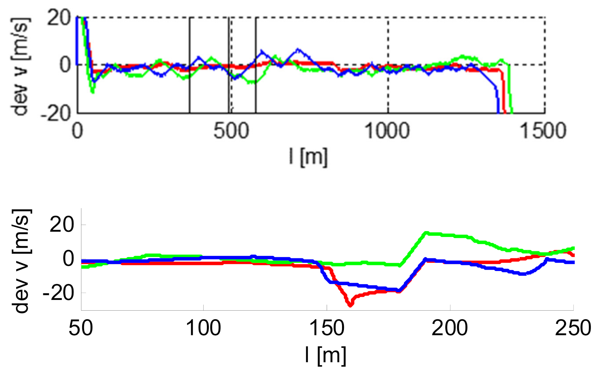
Figure 10 shows the course of the deviation of the speed from the set speed (changed while driving) for the “slalom” ride. For the “route” type ride, the entire ride was performed at a constant speed of V = 50 km/h. For the “slalom” ride, the driver had to follow the speed value displayed on the screen, varying in the range of 20–50 km/h.
While analyzing the obtained experimental waveforms of the lateral deviation from the track axis and deviations from the required driving speed of one of the drivers, a preliminary assessment was made. However, an unequivocal answer can only be obtained from the results of statistical analyses of experimental studies with the use of appropriate confirmatory—confirming or confirmatory—rejecting procedures described in our algorithm. So, having conducted the said analyses, it was found that eco steering wheels in the “route” test have poorer quality indicators than the standard steering wheel: they increase the yawing effect, the effect of uneven driving speed, and the effect of lateral distance from the designated drive line. However, no case of falling out of the permitted lane was registered for any of the steering wheels.
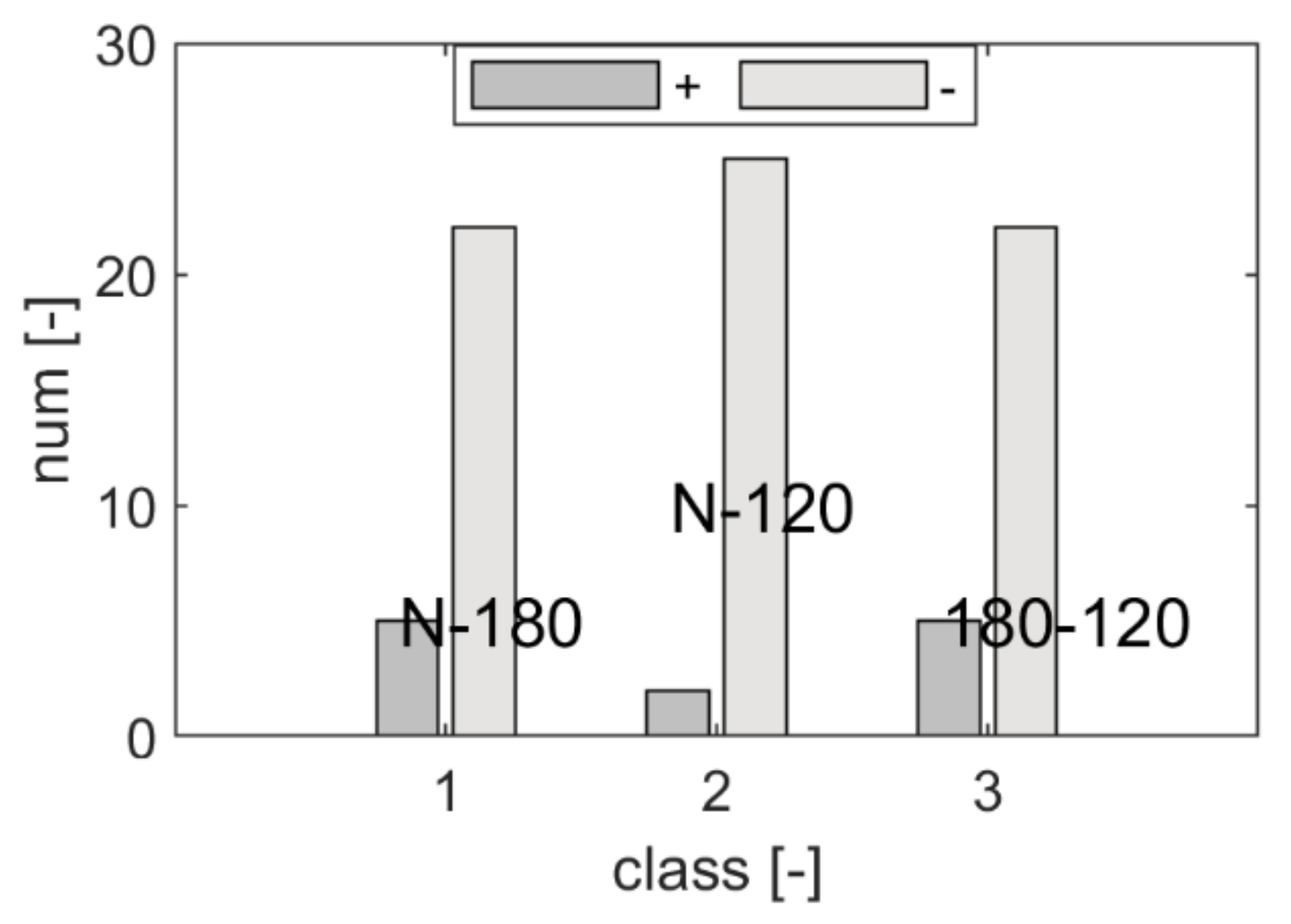
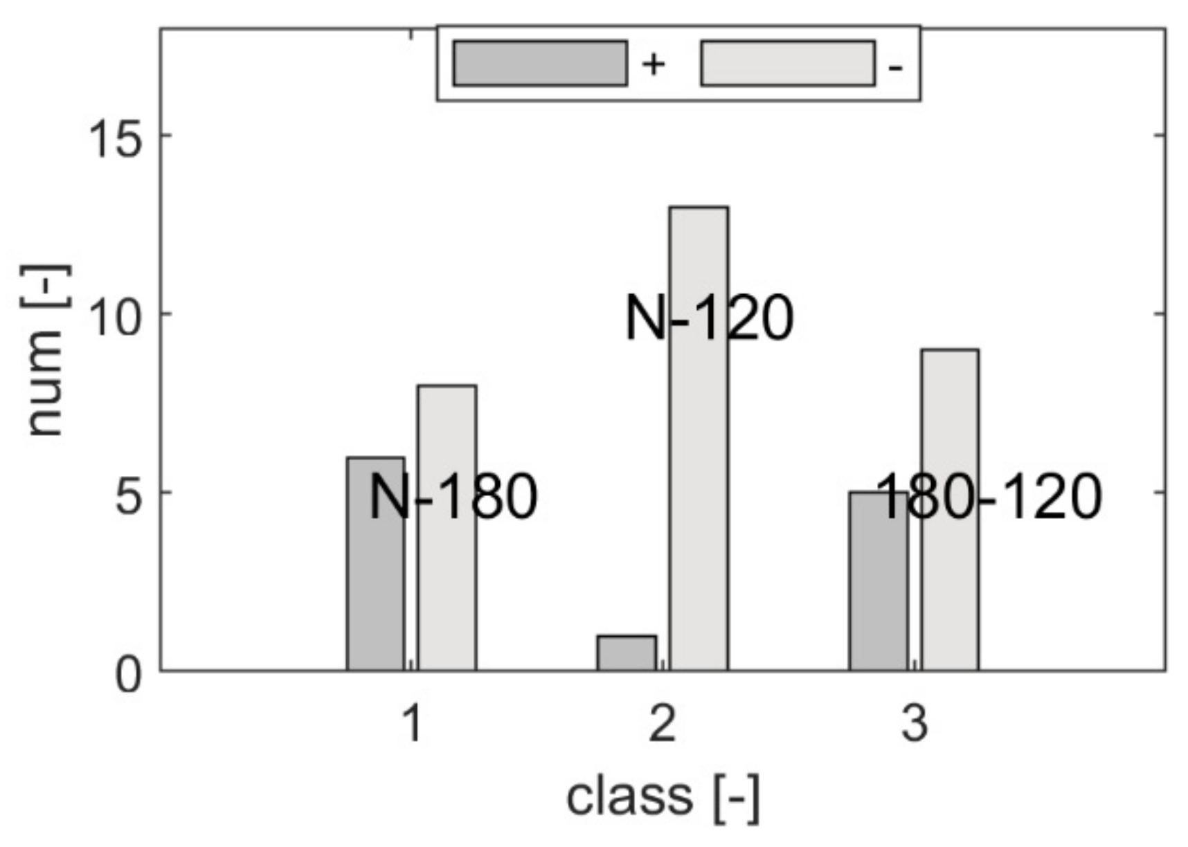
Figure 11 shows the results of post hoc analysis for the value of the lateral deviation from the designated drive line. The differences in the number of paired observations are presented. The results are marked as follows: N: observations assigned to the standard steering wheel, 120: observations assigned to the ECO 120 steering wheel, 180: observations assigned to the ECO 180 steering wheel, 1: difference class N-120, 2: difference class N-180, 3: difference class 120–180. Dark bars indicate a positive result, and lighter ones a negative result. Since the higher value of the indicator constituting the observations determines the deterioration of the ride quality, the obtained result confirms a significantly lower functionality of the ECO steering wheels as compared to the standard steering wheel (for the indicator in question).
In the case of the “slalom” test, no statistically significant differences were found between the distributions of random variables of the paired observations. This result means that there is no reason to reject the hypothesis that the steering wheel functionality is identical.
3.2. Analysis of the Results Obtained from EMG Measurements
As before, the results for one tested driver are presented.
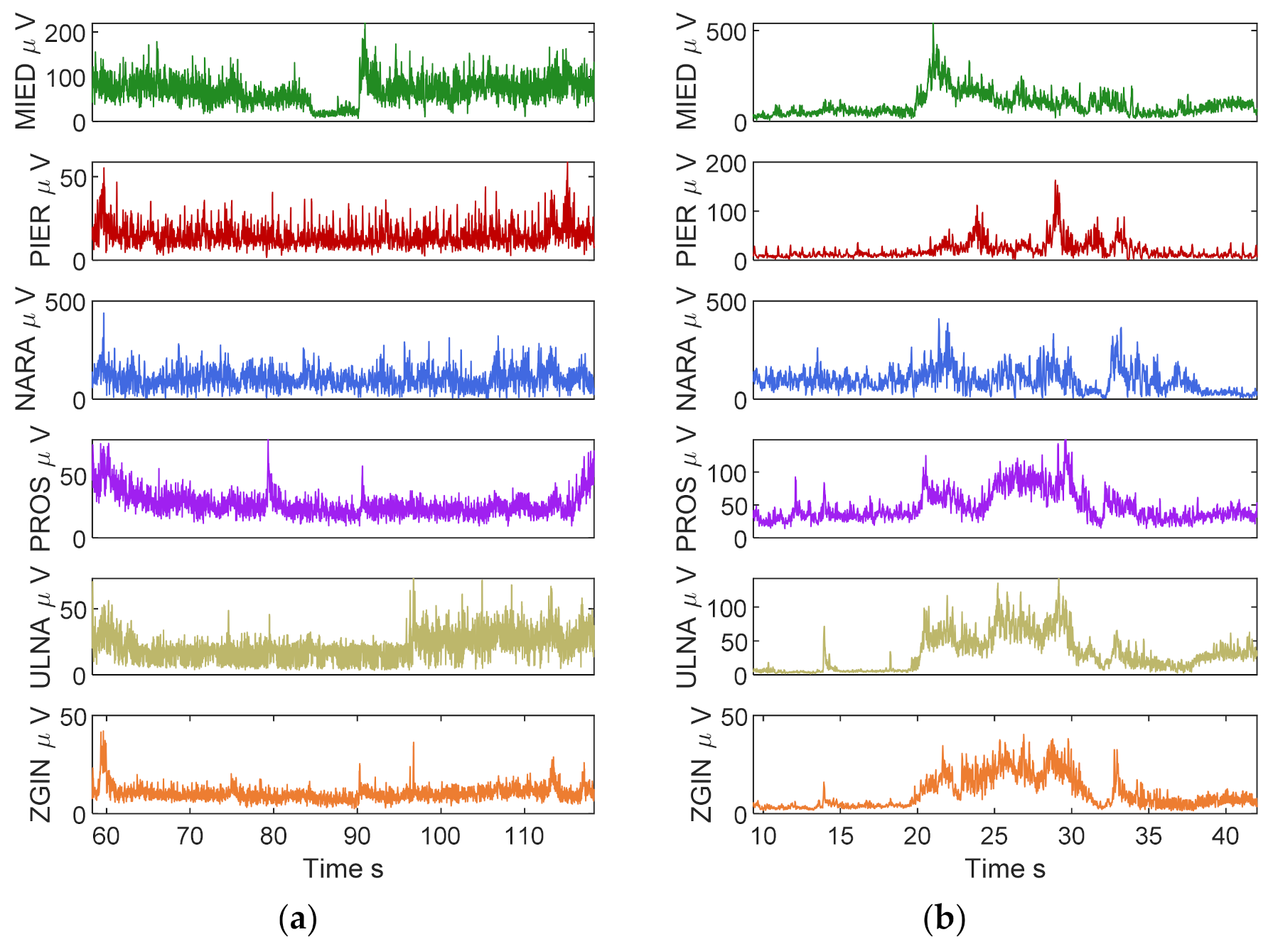
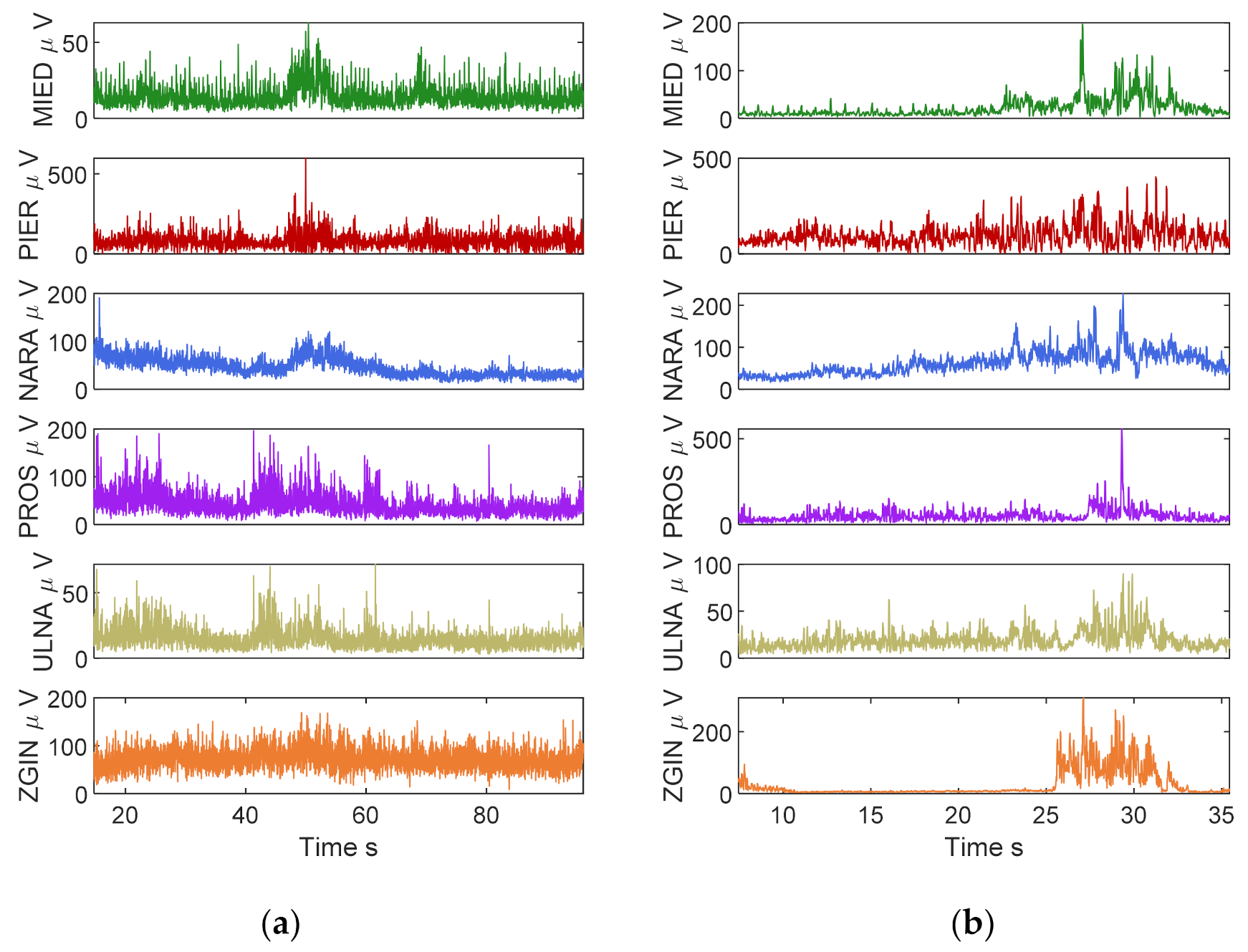
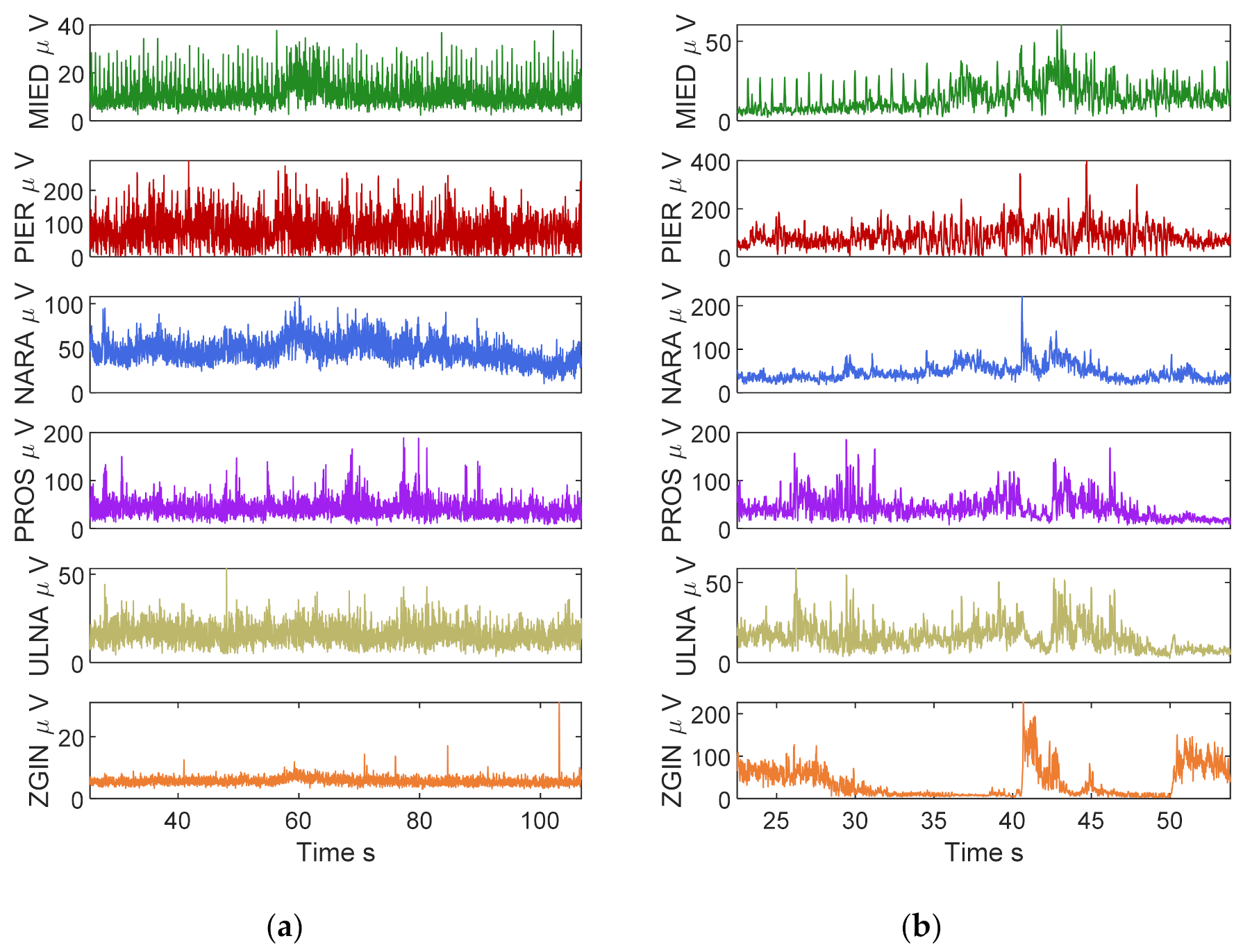
Figure 12 shows the graphs of the EMG RMS signal for the NOR steering wheel,
Figure 13 for the ECO 120 steering wheel, and
Figure 14 for the ECO 180.
In the case of the standard NOR steering wheel, the most active muscles are PROS and ZGIN, i.e., the extensor and flexor of the fingers. Their activity is related to gripping the steering wheel.
The results presented in
Figure 12,
Figure 13 and
Figure 14 show, first of all, differences in the muscle load for particular types of steering wheels. For the standard steering wheel, for example, a smaller load on the first interosseous muscle can be observed, as compared to other types of steering wheels. In the case of ECO 120, we observe a statistically reliable increased activity of the flexor muscle of the fingers (in relation to the standard steering wheel). The greatest load on the wrist flexor is for the ECO 120 steering wheel, which is probably due to the so-called phenomenon of “yawing”, i.e., the need to correct the vehicle movement due to excessive sensitivity of the steering system. A similar conclusion can be drawn for the pectoralis major muscle. The described conclusions were repeatable for approx. 80% of the analyzed sample of drivers. In the case of 20%, there were differences, which, however, did not have a constant trend. No physical fatigue of the muscles was observed in any of the cases, which would be reflected in the RMS signal trend. Perhaps it was also due to the relatively short duration of the experiment. The subjective assessment of the comfort of using a given type of steering wheel was assessed with the use of questionnaire surveys. The participants of the experiment had to indicate which steering wheel suited them best. The results were quite interesting: 57% of the participants indicated a steering wheel with a standard gear ratio, 23% a steering wheel with an ECO 120 gear ratio, and 20% a steering wheel with an ECO 180 gear ratio. In the case of people with disabilities, other results can be expected due to the frequent correlations between the impairment of the lower locomotor system and the partial impairment of the upper locomotor system, which prevent the use of a standard steering wheel (with pedals). Different preferences of the respondents in the choice of steering wheel prove that there is a need to adjust steering wheel parameters to the individual expectations of drivers.
However, a complete answer to the question about the possible change in muscle loads during the use of different types of steering wheels can only be obtained from a statistical analysis. In this case, its limitations should be described. First of all, the number of drivers for whom EMG tests were performed is much smaller than the number of drivers who performed simulator rides. This fact translates into a significant reduction in the test power in the case of the application of the confirmatory—rejecting procedure. In addition, the rides made were short (a few minutes), which turned out to be too short for the rides to generate significant muscle fatigue. For this reason, the collected data turned out to be insufficient to perform a full analysis. Only in the case of the study of the differences in the EMG RMS trend of the pectoral muscle (pectoralis) was there a statistically reliable result, confirming greater muscle effort when driving the car with ECO steering wheels. This situation is illustrated in
Figure 15.
4. Critical Analysis of the Results
Based on the results of the experiment, it was possible to demonstrate that in terms of quality indicators, such as the criterion of deviation from the route line and “yawing”, ECO steering wheels are less functional both in the “route” and “slalom” test. It was also possible to demonstrate (however, for only one muscle group) that the use of this steering wheel causes greater muscle fatigue. The authors of the experiment are aware of the need to conduct research that will enable them to broaden their knowledge on this subject, i.e.:
The ECO steering wheel is intended to be used by both able-bodied and disabled people. For this reason, its design differs from the standard solutions of the normal steering wheel. On the other hand, the research was carried out on a group of able-bodied drivers accustomed to using standard steering wheels. It should be repeated in the group of drivers with reduced mobility.
In addition, it should also be verified whether prior training could improve the experiment results for ECO steering wheels.
If the functionality of ECO steering wheels was to be compared with other solutions (e.g., joystick) in the future, it would be worth knowing which of the factors (removing the pedals or reducing the sensitivity of the steering gear system (gear ratio)) has a greater impact on reducing its functionality in relation to the normal steering wheel. However, the search for answers to the last question would require a significant extension of the scope of research by two new types of steering wheels: 1) normal gear without pedals, and 2) pedals and reduced gear ratio.
5. Nonstandard Steering System Designs and Related Certification and Driving License Examination Issues
Universal design and “custom design” necessarily require a re-evaluation of many issues related to the certification of new solutions and obtaining driving licenses. The problem becomes particularly complex when we consider that there is a breakthrough in road vehicle technology. It is primarily about introducing vehicles with various levels of automation (according to the SAE classification), including vehicles at various levels of autonomy. According to the authors, the issues analyzed in this paper can be of great help here. Below is an outline of the solutions based on three-layer diagrams. The basic assumptions for their creation can be formulated in the following points:
New solutions, in a technical sense, should be subject to detailed reliability testing, e.g., steer by wire systems or technical solutions, such as a multifunction steering wheel.
The proposal of new solutions should be subject to preliminary tests mainly through testing in dynamic simulators or biomechanical tests with the use of EMG, and in natural conditions on roads or closed tracks, to determine, inter alia, the scope of changes in the “feedback force” and gear ratios in the steering system.
Trainings and examinations for persons with reduced mobility should, in some cases, be carried out in dynamic simulators.
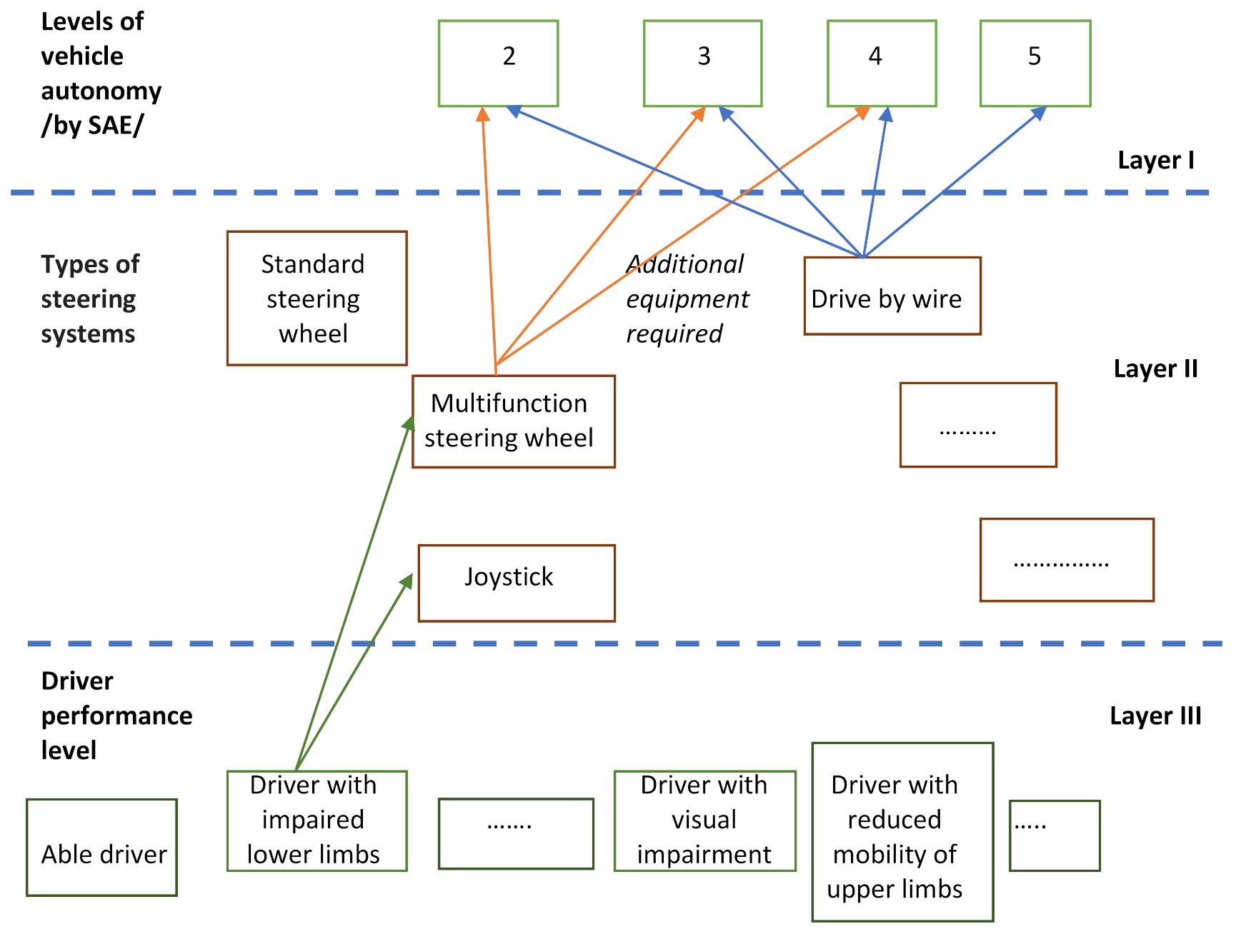
Custom steering system designs increase the number of active users by adapting interface devices to the needs and limitations of drivers who are not fully able-bodied. This is possible if the vehicle is equipped with additional systems, such as drive by wire. The purpose of integrated design is, on the one hand, to provide a custom solution that is so intuitive and simple that it can be used by people with different constraints, while at the same time, there is some scope for individual customization. However, this requires close cooperation of designers with the vehicle end users in the design process. The next necessary stage is training with the use of the proposed interface solutions. Each driver would be given a diagram that defines the driver’s rights. It would also be the same as the exam that was conducted. An example diagram is shown in
Figure 16.
Layer I in the case given in
Figure 16 concerns the SAE classification. It can be seen how important it is to adopt the same (common on a global scale) classification. The work carried out, for example, under the UNECE World Forum for Harmonization of Vehicle Regulations (WP.29) on the regulation and harmonization of road regulations is of paramount importance here. Layer II, which will be developed along with the enhancement of new techniques, should include, among others, the type of steering system and additional equipment required. For example, in the case of steering the vehicle with brain waves, it is necessary to equip the cabin with screens that separate the driver’s cabin from external electromagnetic interference. Layer III, on the other hand, contains a description of the disability. This list can be expanded and supervised by legal regulations.
Figure 16 illustrates the following case:
The diagram concerns a person with a disability of the lower limbs (layer III). The driver can use a multifunction steering wheel or joystick. Additionally, the vehicle must be equipped with a drive by wire system. The driver is authorized to drive automation level 2, 3, or 4 according to the SAE classification. Level 5 means complete autonomy and will not have an interface (steering wheel) that would allow the driver to interfere with driving the car. The vehicle can only accept the trip’s destination.
The above proposal should be considered as initially outlined. A number of additional problems should be taken into account when introducing it, e.g., how to eliminate the impact of the so-called simulator disease for research carried out on dynamic car simulators.
6. Conclusions
Providing people with various motor or sensory limitations with the possibility to drive vehicles will allow them to be more active in their social life and more independent. The current practice consists of adapting the vehicle to the needs of a given person, using solutions available on the market that best suit the driver with a given disability. Nevertheless, the choice of the device does not always allow for efficient and easy steering. There is a need to search for solutions that are universal on the one hand and, on the other hand, still have a certain range of possibilities for individual adjustment. As part of the Eco-Mobility project, when designing a universal eco-car, it was equipped with a multifunctional steering wheel, which was anthropometrically verified, i.e., dimensioned to 95% of users. Only in experimental tests in a car simulator was it possible to evaluate the functionality of the new solution. The research was carried out on a sample of 30 men who did not have any motor limitations and who use standard steering wheels on a daily basis. The planned further tests will concern people using active wheelchairs, but as mentioned, it will require radical changes to the simulator’s cabin in order to locate the wheelchair in it. Healthy drivers have specific driving habits and the short time spent on familiarizing themselves with the new steering wheel was not enough for them to feel its “sensitivity/responsiveness”. In the case of people with disabilities of the lower limbs, there are usually also motor limitations of the upper limbs and, above all, the fingers. A smaller range of rotation of the ECO steering wheel and, at the same time, less movement of the limbs, in their case, may be an advantage and a positive feature of this solution.
The analysis of the test results showed the influence of the multifunction steering wheel parameters on the quality of maneuvers and the load on the driver’s muscles. The obtained values of the adopted indicators confirmed a significantly lower functionality of ECO steering wheels in relation to the standard steering wheel in the “route” test. In the case of the “slalom” test, no statistically significant differences were found between the distributions of random variables of the paired observations. It can be assumed that the proposed solution of the multifunction steering wheel was not suited to the group of able-bodied drivers. Therefore, it seems that the thesis about the necessity to adapt the steering system to the individual characteristics of the driver is correct, in particular when it concerns people with reduced mobility. It can be obtained by integrating universal design and “custom design”. This direction in the design process seems to be the only right one, as drivers with disabilities cannot use the standard steering system in most cases. On the other hand, the proposed solutions, apart from their reliability and safety, should minimize the stigmatization of users, i.e., they should be intended for all drivers with the possibility of minor improvements in special cases.
The development of the automotive industry, including the introduction of drive by wire technology, and the progressive automation of vehicles (partial autonomy) create completely new perspectives. In this case, the problem is also testing new solutions and granting permits to drive vehicles (in particular in relation to people with reduced mobility). Therefore, measures are taken to develop new rules for training drivers depending on the level of automation in the driven car. The three-layer diagrams proposed by the authors seem to be one of the interesting proposals defining the configuration of the steering system and the required skills obtained, for example, during training courses allowing driving at a specific level of automation and with an adapted steering system.
Author Contributions
Conceptualization, I.G., M.K., and W.C.; data curation, I.G.; formal analysis, M.K.; funding acquisition, W.C.; investigation, I.G., M.K., and W.C.; methodology, I.G., M.K., and W.C.; project administration, W.C.; resources, I.G. and W.C.; software, M.K. and W.C.; supervision, W.C.; validation, I.G., M.K., and W.C.; visualization, I.G. and M.K.; writing—original draft, I.G., M.K., and W.C.; writing—review and editing, I.G. and M.K. All authors have read and agreed to the published version of the manuscript.
Funding
European Regional Development Fund: Eco Mobility Project (UND-POIG.01.03.01-14-154).
Institutional Review Board Statement
The study was conducted according to the guidelines of the Declaration of Helsinki, and approved by the Ethics and Bioethics Committee Cardinal Stefan Wyszyński University in Warsaw (KEiB–6/2015).
Informed Consent Statement
Informed consent was obtained from all subjects involved in the study.
Data Availability Statement
The data presented in this study are available on request from the corresponding author.
Conflicts of Interest
The authors declare no conflict of interest.
References
- SAE International Releases Updated Visual Chart for Its “Levels of Driving Automation” Standard for Self-Driving Vehicles. Available online: https://www.sae.org/news/press-room/2018/12/sae-international-releases-updated-visual-chart-for-its-%E2%80%9Clevels-of-driving-automation%E2%80%9D-standard-for-self-driving-vehicles (accessed on 16 August 2021).
- Convention on the Rights of Persons with Disabilities. Available online: https://www.un.org/disabilities/documents/COP/crpd_csp_2017_4.pdf (accessed on 16 January 2021).
- Polmans, K. Steer-By-Wire Systems—Safety, Comfort & Individuality, Auto Tech Review, Digital Edition. Available online: https://autotechreview.com/technology/steer-by-wire-systems-safety-comfort-individuality (accessed on 16 January 2021).
- Mortazavizadeh, A.A.; Ghaderi, A.; Ebrahimi, M.; Hajian, M. Recent Developments in the Vehicle Steer-by-Wire System. IEEE Trans. Transp. Electrif. 2020, 6, 1226–1235. [Google Scholar] [CrossRef]
- Fahami, H.; Zamzuri, H.; Mazlan, S. Development of Estimation Force Feedback Torque Control Algorithm for Driver Steering Feel in Vehicle Steer by Wire System: Hardware in the Loop. Int. J. Veh. Technol. 2015, 2015, 314597. [Google Scholar] [CrossRef] [Green Version]
- Basmajian, J.V.; De Luca, C.J. Muscles Alive Their Function Revealed by Electromyograph; Williams Wilkins: Baltimore, MD, USA, 1985. [Google Scholar]
- Choromański, W.; Grabarek, I.; Kozłowski, M. Research on an innovative multifunction steering wheel for individuals with reduced mobility. Transp. Res. Part F Traffic Psychol. Behav. 2019, 2019, 178–187. [Google Scholar] [CrossRef]
- Kozłowski, M. Assessment of safety and ride quality based on comparative studies of a new type of universal steering wheel in 3D simulators. Eksploat. I Niezawodn. 2016, 18, 481–487. [Google Scholar] [CrossRef]
- Grabarek, I.; Kozłowski, M.; Fiok, K.; Choromański, W. Zagadnienie oceny aktywności mięśni podczas kierowania nowym typem wielofunkcyjnej kierownicy w samochodzie elektrycznym. Pr. Nauk. Politech. Warszawskiej. Transp. 2017, 119, 137–148. [Google Scholar]
- Aerospace Industries, sp. z o. o. Available online: https://www.ai.com.pl/ (accessed on 16 January 2021).
- Eco-Mobilność. Available online: http://www.eco-mobilnosc.pw.edu.pl/ (accessed on 16 January 2021).
- Konrad, P. The ABC of EMG. In A Practical Introduction to Kinesiological Electromyography; Noraxon Inc.: Scottsdale, AR, USA, 2005. [Google Scholar]
- Balasubramanian, V.; Adalarasu, K. EMG-based analysis of change in muscle activity during simulated driving. J. Bodyw. Mov. Ther. 2007, 11, 151–158. [Google Scholar] [CrossRef]
- Carrino, F.; Carrino, S.; Caon, M.; Angelini, L.; Khaled, O.A.; Mugellini, E. In-vehicle natural interaction based on electromyography. Proc. Automot. UI 2012, 2012, 12. [Google Scholar]
- Nakamura, H.; David, A.; Mark, M. Is grip strength related to neuromuscular admittance during steering wheel control? In Proceedings of the 2011 IEEE International Conference on Systems, Man, and Cybernetics (SMC), Anchorage, AK, USA, 9–12 October 2011. [Google Scholar]
- Park, J.; Shinsuk, P. Reduction of arm fatigue and discomfort using a novel steering wheel design. Int. J. Precis. Eng. Manuf. 2014, 15, 803–810. [Google Scholar] [CrossRef]
- Pick, A.J.; Cole, D.J. Neuromuscular dynamics in the driver–vehicle system. Veh. Syst. Dyn. 2006, 44, 624–631. [Google Scholar] [CrossRef]
- Abbink, D.A.; Mulder, M.; Van Paassen, M.M. Measurements of muscle use during steering wheel manipulation. In Proceedings of the 2011 IEEE International Conference on Systems, Man, and Cybernetics (SMC), Anchorage, AK, USA, 9–12 October 2011. [Google Scholar]
- Hostens, I.; Herman, R. Assessment of muscle fatigue in low level monotonous task performance during car driving. J. Electromyogr. Kinesiol. 2005, 15, 266–274. [Google Scholar] [CrossRef] [PubMed]
- Pick, A.J.; David, J.C. Measurement of driver steering torque using electromyography. J. Dyn. Syst. Meas. Control 2006, 128, 960–968. [Google Scholar] [CrossRef]
- Wiszomirska, I. Vivo Consultation of Muscle Selection and Electrode Placement; Józef Piłsudski University of Physical Education in Warsaw: Warsaw, Poland, 2015. [Google Scholar]
Figure 1.
Car driving simulator of ETC PZL Aerospace Industries. Source: ETC PZL [
10].
Figure 1.
Car driving simulator of ETC PZL Aerospace Industries. Source: ETC PZL [
10].
Figure 2.
(
a) Eco-car created within the [
11] project, (
b) multifunctional steering wheel the car is equipped with, (
c) tested steering wheel installed in the simulator.
Figure 2.
(
a) Eco-car created within the [
11] project, (
b) multifunctional steering wheel the car is equipped with, (
c) tested steering wheel installed in the simulator.
Figure 3.
(
a) “Route” type adapted from [
7], (
b) “slalom” type adapted from [
8].
Figure 3.
(
a) “Route” type adapted from [
7], (
b) “slalom” type adapted from [
8].
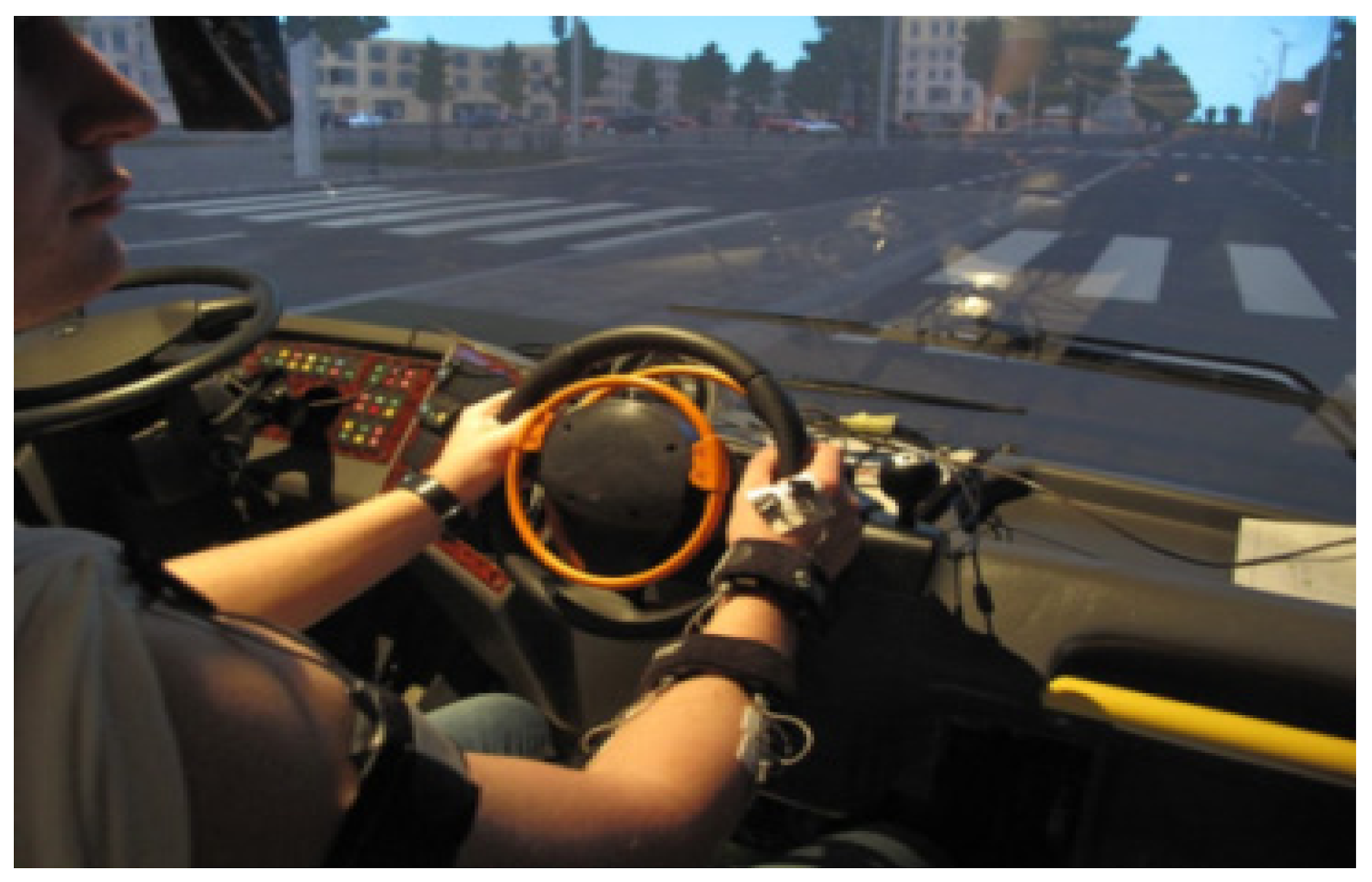
Figure 4.
Simulator screen image: reference trajectory.
Figure 4.
Simulator screen image: reference trajectory.
Figure 5.
Visualization of the examined muscles/own work based on anatomical atlases.
Figure 5.
Visualization of the examined muscles/own work based on anatomical atlases.
Figure 6.
Location of electrodes for surface EMG measurement used in the experiment.
Figure 6.
Location of electrodes for surface EMG measurement used in the experiment.
Figure 7.
Interpretation of the h parameter. The parameter is measured in the radial direction to the reference trajectory and concerns the geometric center of the vehicle.
Figure 7.
Interpretation of the h parameter. The parameter is measured in the radial direction to the reference trajectory and concerns the geometric center of the vehicle.
Figure 8.
Values of the h parameter for the “route” type ride: (a) NOR steering wheel: red, (b) ECO 180 steering wheel: green, (c) ECO 120 steering wheel: blue.
Figure 8.
Values of the h parameter for the “route” type ride: (a) NOR steering wheel: red, (b) ECO 180 steering wheel: green, (c) ECO 120 steering wheel: blue.
Figure 9.
Values of the h parameter for the “slalom” ride: (a) NOR steering wheel: red, (b) ECO 180 steering wheel: green, (c) ECO 120 steering wheel: blue.
Figure 9.
Values of the h parameter for the “slalom” ride: (a) NOR steering wheel: red, (b) ECO 180 steering wheel: green, (c) ECO 120 steering wheel: blue.
Figure 10.
Graphs of deviations of the driving speed from the set value for three steering wheels and two types of rides: “route” and “slalom”. The graphs are color-coded: red: NOR steering wheel, green: ECO 180 steering wheel, blue: ECO 120 steering wheel.
Figure 10.
Graphs of deviations of the driving speed from the set value for three steering wheels and two types of rides: “route” and “slalom”. The graphs are color-coded: red: NOR steering wheel, green: ECO 180 steering wheel, blue: ECO 120 steering wheel.
Figure 11.
Graph of the number of observation classes for paired values of the effective transverse distance from the designated route line.
Figure 11.
Graph of the number of observation classes for paired values of the effective transverse distance from the designated route line.
Figure 12.
Graphs of the EMG RMS signal for the NOR steering wheel: (a) “route” type ride, (b) “slalom” type ride. The order of the graphs corresponds to the following muscles: MIE: “interosseous”, PIER: “pectoralis”, NARA: “deltoideus”, PROS: “extensor”, ULNA: “ulnaris”, ZGIN: “flexor”.
Figure 12.
Graphs of the EMG RMS signal for the NOR steering wheel: (a) “route” type ride, (b) “slalom” type ride. The order of the graphs corresponds to the following muscles: MIE: “interosseous”, PIER: “pectoralis”, NARA: “deltoideus”, PROS: “extensor”, ULNA: “ulnaris”, ZGIN: “flexor”.
Figure 13.
Graphs of the EMG RMS signal for the ECO180 steering wheel: (a) “route” type ride, (b) “slalom” type ride. The order of the graphs corresponds to the following muscles: MIE: “interosseous”, PIER: “pectoralis”, NARA: “deltoideus”, PROS: “extensor”, ULNA: “ulnaris”, ZGIN: “flexor”.
Figure 13.
Graphs of the EMG RMS signal for the ECO180 steering wheel: (a) “route” type ride, (b) “slalom” type ride. The order of the graphs corresponds to the following muscles: MIE: “interosseous”, PIER: “pectoralis”, NARA: “deltoideus”, PROS: “extensor”, ULNA: “ulnaris”, ZGIN: “flexor”.
Figure 14.
Graphs of the EMG RMS signal for the ECO120 steering wheel: (a) “route” type ride, (b) “slalom” type ride. The order of the graphs corresponds to the following muscles: MIE: “interosseous”, PIER: “pectoralis”, NARA: “deltoideus”, PROS: “extensor”, ULNA: “ulnaris”, ZGIN: “flexor”.
Figure 14.
Graphs of the EMG RMS signal for the ECO120 steering wheel: (a) “route” type ride, (b) “slalom” type ride. The order of the graphs corresponds to the following muscles: MIE: “interosseous”, PIER: “pectoralis”, NARA: “deltoideus”, PROS: “extensor”, ULNA: “ulnaris”, ZGIN: “flexor”.
Figure 15.
Number of observation classes of paired EMG RMS trend values of the pectoral muscle in the “route” test.
Figure 15.
Number of observation classes of paired EMG RMS trend values of the pectoral muscle in the “route” test.
Figure 16.
The concept of three-layer diagrams defining the driving license for a road vehicle.
Figure 16.
The concept of three-layer diagrams defining the driving license for a road vehicle.
Table 1.
Analyzed muscles.
Table 1.
Analyzed muscles.
| Muscles | Reference Level (µV) (the Highest RMS Value with a Time Window of 500 (ms))/Xmax/ |
|---|
| 1491 |
- 2.
Anterior part of the deltoid muscle (deltoideus), NARA
| 867 |
- 3.
Pectoralis major, PIER
| 271 |
- 4.
Surface finger flexor/flexor digitorum superficialis (“finger extensor”), PROS
| 806 |
- 5.
Wrist elbow flexor/flexor carpi ulnaris (“ulnaris flexor”), ULNA
| 308 |
- 6.
Radial wrist flexor/flexor carpi radialis (“finger flexor”)/flexor carpi radialis, ZGIN
| 756 |
| Publisher’s Note: MDPI stays neutral with regard to jurisdictional claims in published maps and institutional affiliations. |
© 2021 by the authors. Licensee MDPI, Basel, Switzerland. This article is an open access article distributed under the terms and conditions of the Creative Commons Attribution (CC BY) license (https://creativecommons.org/licenses/by/4.0/).


