Abstract
Impingement heat transfer is considered one of the most effective cooling technologies that yield high localized convective heat transfer coefficients. This paper studies different configurable parameters involved in jet impingement cooling such as, exit orifice shape, crossflow regulation, target surface modification, spent air reuse, impingement channel modification, jet pulsation, and other techniques to understand which of them are critical and how these heat-transfer-enhancement concepts work. The aim of this paper is to excite the thermal sciences community of this efficient cooling technique and instill some thoughts for future innovations. New orifice shapes are becoming feasible due to innovative 3D printing technologies. However, the orifice shape variations show that it is hard to beat a sharp-edged round orifice in heat transfer coefficient, but it comes with a higher pressure drop across the orifice. Any attempt to streamline the hole shape indicated a drop in the Nusselt number, thus giving the designer some control over thermal budgeting of a component. Reduction in crossflow has been attempted with channel modifications. The use of high-porosity conductive foam in the impingement space has shown marked improvement in heat transfer performance. A list of possible research topics based on this discussion is provided in the conclusion.
1. Introduction
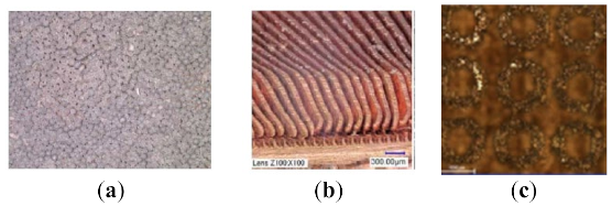
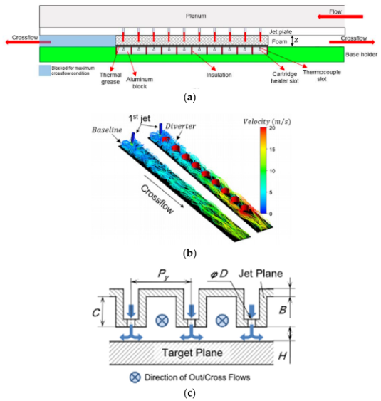
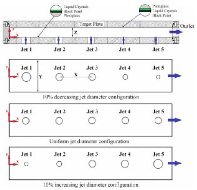
The topic of jet impingement heat transfer has been widely researched, and details of such investigations can be found in [1,2,3]. Common parameters such as jet Reynolds numbers, jet-to-jet, and jet-to-target spacings have been discussed in numerous publications and are not repeated here. The interested reader can get the details from Han et al. [1] and from Figure 1 on the classic and new parameters on impingement cooling. In a recent investigative work, Dutta and Singh [4] discussed the effects of geometrical features on impingement and indicated opportunities in the research and exploration on impingement heat transfer. There are many configurational variables that have been explored in detail in the past, e.g., single jet [5] or array of jets [6], as shown in Figure 1 [7,8]. Fundamental studies include a free jet directed to target surface (Figure 1), a confined jet [9], a slot jet [10], a single jet subjected to initial crossflow [11], a crossflow scheme [6] (Figure 1), an angled jet [12], jet-to-jet spacing (x/d) [13], jet-to-target spacing (z/d) [13], relative arrangement of jets (inline or staggered) [13], impingement channel modification [14], crossflow regulation through variable diameter jets [15], nozzle shape [16], nozzle aspect ratio [17], target surface modification [18], and many more. Some common examples of orifice shape modification are triangular, racetrack, and notched or lobed, in contrast to the conventional circular orifice, which is a preferred choice from a fabrication perspective. Impingement channel modification includes converging or diverging channels, anti-crossflow configurations, whereas target surface modifications include dimples, pins, ribs, and special shapes. Representative examples on the above aspects of jet impingement heat transfer are pictorially presented in Table 1.
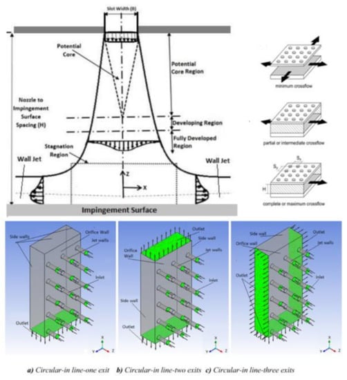
Figure 1.
Different channel flow configurations used in jet-array impingement heat transfer [7,8] (courtesy: open access and ASME) [4].

Table 1.
Representative concepts and factors affecting overall jet impingement heat transfer.
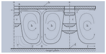
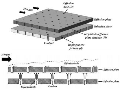
Figure 1 shows a schematic of single and multiple jet configurations used in impingement heat transfer. The spent jet creates a channel flow known as crossflow that deflects downstream jets, causing a reduction in impingement effectiveness. Usually, impingement heat transfer studies involve a small orifice or narrow slot jet. Slot jets can also be used in an array with uniform or non-uniform spacings. The impingement channel passage can have different shapes such as convergent, divergent, or channel-like formations to disengage the crossflow from jet deflection. Jets can be at an angle to the target surface and can be oriented to counter the crossflow deflection.
In this paper, we present the above efforts with our views on the areas of further improvement, and we highlight areas that have not received much attention; we also identify a few topics that can be further explored. With the advancements in metal additive manufacturing, this article may serve as a reference tool for advancements in jet impingement systems to obtain significantly higher performance. First, we present some benchmark studies in the introduction to provide the foundation of any future investigations, and then we present different configurational parameters’ effects on impingement performance and discuss the scope for innovation.
Hollworth and Wilson [31] experimentally studied the flow and thermal field to characterize the entrainment effects for a single jet (working fluid: air) without backplate, which is also known as an orifice plate or insert in a turbine component. The difference between jet and ambient temperatures was varied between 30 °C and 60 °C. The flow and pressure were also measured when the jet was discharged at ambient temperature to calculate the discharge coefficients. In a follow-up work, Hollworth and Gero [32] presented the heat transfer characteristics. The entrainment effects were identified on a free jet, and it was observed that local jet recovery temperature provided a better nondimensional profile of heat transfer. However, the use of local jet recovery temperature is not practical, and therefore current design procedures and correlations use jet exit temperature as the basis of correlations. However, their work indicated that the Nusselt number (Nu) depended on jet exit temperature only if the entrainment temperature was significantly different. Therefore, there is room for research to identify the contribution of entrainment temperature on the spent jet region. The results presented in the current literature use crossflow developed by spent jet and that crossflow also has higher temperature assuming the target surface is hotter. Experimental work with unheated crossflow can identify the effects of jet deflection and temperature entrainment separately.
Baughn et al. [33] experimentally studied the effects of entrainment on a heated circular jet. The jet was issued from a pipe with a different nozzle length-to-diameter ratio (L/D) and not from an orifice; it was a free jet without a backplate. This work showed the effect of L/D on the jet performance, where a smaller L/D had higher heat transfer. An abrupt pipe exit showed higher heat transfer at the stagnation region than a streamlined nozzle. This work also used adiabatic wall temperature with heated jets. These entrainment studies indicated that the heat transfer was affected by the surrounding air temperature and should be considered in the analysis and thermal correlations.
Impingement cooling in stationary turbine components is usually coupled with film cooling. Spent jets exit the component through well-placed film holes to protect the component from the hot gas path’s hostile environment. Immarigeon and Hassan [34] numerically studied the coupling of impingement and film cooling in gas turbines. They developed a new impingement structure with a film exit. Three round jets impinged and then dispersed through the film hole. The film effectiveness was predicted to be lower than a regular film hole, but the impingement on the film lip helped to cool the boundary layer and therefore argued to help with keeping the film itself cooler than the normal injection. Another work on impingement and film cooling was experimentally analyzed by Mensch and Thole [35]. They systematically evaluated the cooling effectiveness of film and impingement separately and then used both internal and external cooling schemes to illustrate that the best performance was obtained when both cooling schemes were used. Only film cooling was more effective near the hole exit, and only impingement provided a better-distributed effectiveness but with lower magnitude. The combination of film and impingement as used in the industry provided the best cooling arrangement in the airfoil platform area. Optimization of impingement along with film cooling is an active research area. Mousavi and Rahnama [36] carried out detailed CFD analysis to optimize jet and film holes with artificial neural networks and genetic algorithms. They showed improvement but also illustrated that the computation demand is significant before any optimized results can be obtained. A correlation-based model with reduced computational requirements has been used by Dutta and Smith [37,38,39].
Impingement heat transfer simulation is an active area of thermal research, and researchers are exploring performance and quality improvements by different mathematical models even on simple round jets with smooth target surfaces. Issac et al. [40] compared different numerical models to predict heat transfer with a single free round jet on a smooth surface. As discussed in this paper, the study of free jets is perhaps not the most useful as the recirculation caused in the presence of a backplate is very important and can alter the heat transfer pattern significantly. Katti et al. [41] provided experimental measurement of single free jet heat transfer, and Jeffers et al. [42] studied the stagnation zone with a single confined and submerged jet. They used a long tube to develop flow at the jet exit. They observed that stagnation pressure can migrate towards the jet exit and alter the velocity profile coming out of the jet in the proximity of the jet with the target surface.
Li et al. [43] experimentally measured perpendicular and inclined jets and found that inclined holes do not significantly alter heat transfer patterns. It is possible that the short orifices used were not long enough to provide a direction for the exiting jets. Ekkad and Han [44] illustrated the transient liquid crystal thermography technique on impingement and other gas-turbine cooling technologies. Their work revealed important details on two-dimensional (2D) heat transfer distribution that were not available before without a messy Naphthalene sublimation technique. The benefits of obtaining a 2D heat transfer distribution on the design of impingement configurations are discussed in a later section of this paper.
Routine numerical simulation of impingement heat transfer has been done by Kacar et al. [45] to show that the parameter variation effects can be successfully captured with numerical models. More detailed work was performed by Zuckerman and Lior [46] to illustrate the physics of the flow. The stagnation region was modelled in detail by Zu et al. [47] with seven different turbulence models. These were essentially numerical model calibration works and did not add much to the thermal domain knowledge. In some turbine components, impingement and film cooling are tied together. In that scenario, a better impingement may be detrimental to film cooling as film coolant is nothing but the spent jets. A better impingement scheme increases spent jet temperature and that increases the film temperature. Relative interactions are discussed in detail by Williams et al. [48]. They found an overall cooling effectiveness and it was biased towards better impingement cooling.
2. Benchmark Studies on Impingement Heat Transfer
This section highlights a collection of publications that a beginner researcher may browse to understand established parameters affecting impingement cooling. The Heat Transfer Laboratories led by Prof. R.J. Goldstein of the University of Minnesota, and the late Prof. D. E. Metzger of Arizona State University published many detailed works on impingement heat transfer in the late 1970s and early 1980s. Behbahani and Goldstein [49] developed local heat transfer from a flat target plate with a staggered array of circular impingement jets. They varied the jet-to-jet and jet-to-target plate distances and jet Reynolds numbers. They realized the importance of L/D (L is orifice length) and used a short orifice of L/D = 1, where two orifices—5 mm and 10 mm were used. One end of the chamber was closed, and the other end was open. The results set the benchmark in impingement heat transfer; however, the effect of exit length (distance between the last jet row (closest to exit plane) and the exit) effect was not studied. Exit lengths can have a significant effect on the heat transfer pattern since it affects the pressure distribution in the impingement channel, which in turn can modify the jet mass flux; and hence the interaction between emanating jets and distribution of accumulated crossflow discharge can be dependent on the exit length. A short exit length can arguably strengthen the jets nearer to the exit and can create stronger heat transfer near the exit than the closed end.
There is a room for optimization of the hole spacings based on exit length restriction. The real engine impingement hole sizes are smaller than those investigated experimentally and the scaling of Nusselt number with Reynolds number from laboratory testing to engine condition is a topic to be considered for further investigation. Florschuetz et al. [50] provided another benchmark experimental paper on jet arrays with crossflow from the late Prof. Metzger’s laboratory. Array jet impingement was studied for inline and staggered configurations under maximum crossflow condition, where correlations were provided for jet mass flux distribution, crossflow mass flux distribution in impingement channel, and row-wise averaged Nusselt number in reference to the row closest to the blocked end. These empirical correlations are now widely accepted in industries and used as validation data for many numerical investigations on impingement heat transfer as well as benchmarking jet impingement experimental facilities. Another notable work was carried out by Kercher’s group as in Kercher and Tabakoff [51], who in the 1970s identified the effect of spent jets on impingement heat transfer.
3. Key Aspects of Impingement Heat Transfer Related to Gas-Turbine Technologies
In this section, we have covered different factors involved in jet impingement system that influence the resultant convective heat transfer coefficients on the target wall, and we reviewed some cooling strategies that designers can consider for advancing this efficient cooling technology. Many of the traditional impingement aspects are discussed in the introduction section and are not repeated here. To maintain a balance between these two sections of this paper (1 and 3), we have divided references and understand that some publications could have been discussed in both. However, due to space limitations, we have tried to keep the discussion short and concise.
Figure 2 shows the turbine schematic and the components that use impingement cooling. These sketches are taken from different sources and more details on cooling configurations of these turbine components can be found in these references [52,53,54,55,56]. The combustor liner and shroud use arrays of jet holes that are usually customized for those individual components. The rotor blade has cast or in-built impingement structures and the stationary vane customarily has sheet metal inserts with different impingement hole patterns.
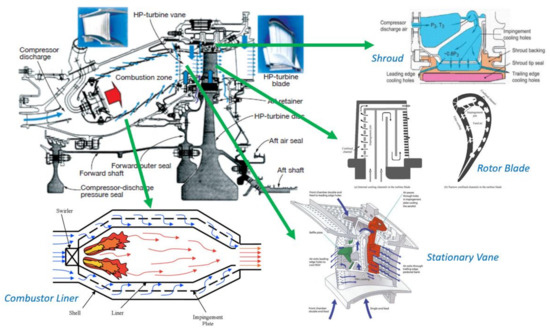
Figure 2.
Use of impingement cooling in different components of gas turbine. Image courtesy: Overall turbine assembly from ccj-online [52], Combustor Liner [53], Shroud [54], Rotor Blade [55], Stationary Vane [56].
Several configurational aspects have been considered here like entrainment caused by the presence of a backplate. Following discussions are about the use of modified backplates, jet nozzle shapes, and target surface modifictions to alter impingement heat transfer. The modifications in the nozzle geometry may not necessarily improve the convective heat transfer coefficient (h) when compared with simple round orifices, which are easily manufacturable, but may provide better pressure drop performance. Target surface modifications, on the other hand, can be efficient when roughened by micro-scale features in terms of fin effectiveness and net heat dissipation (hA: where A is the wetted surface area) with respect to required pumping power in reference to relatively smooth targets. The following sub-sections are aimed towards not simply presenting some selected articles addressing the above areas, but are intended to stimulate thoughts on how one can further enhance jet impingement performance, given that we now have significantly more freedom in the design space due to the advancement in the materials and additive manufacturing.
3.1. Jet Entrainment
Jet entrainment studies by Hollworth and Wilson [31], Hollworth and Gero [32], and Baughn et al. [33] have been discussed above. These entrainment studies indicated that the heat transfer was affected by the surrounding air temperature and should be considered in the analysis. Such studies have become popular lately. Typically, we see the supply plenum temperature used as the reference fluid temperature for jet impingement heat transfer in both single and array jet impingement. The entrainment effects are even stronger in array jet impingement, which has a confined impingement channel. The closely spaced jets result in a counter-rotating vortex pair, and it is possible that the usage of plenum temperature as the reference may be suitable for the stagnation region and the jet footprint, but regions between adjacent jets may have a different reference temperature. This entrainment effect will also depend on the jet-to-target spacing and jet-to-jet spacing, as well as whether the jets were arranged inline or staggered and the subsequent crossflow exit schemes. To address this problem, we believe that computational studies can play an important role in predicting the local fluid temperature in the impingement channel where these predictions can complement the experimental measurements. Note that the adiabatic wall temperature usage as the fluid reference temperature may still be the best choice, which can be easily obtained in a typical steady-state experiment. Transient experiments, on the other hand, with time-varying plenum temperature have limitations in this regard, and hence the plenum temperature continues to be used as the reference fluid temperature.
3.2. Impingement-Effusion Cooling
The cooling design of gas-turbine blades involves both internal and external cooling, where internally routed coolant is bled off through strategically placed effusion holes (or film holes). The coolant extraction can happen in the serpentine passages featuring rib turbulators [57] and through adjacent holes placed between impinging jets’ footprints in leading-edge and mid-chord sections of gas-turbine blades. Impingement-effusion cooling scheme can also be found in the combustor liner wall cooling [58]. Ekkad et al. [57] presented detailed heat transfer coefficient for impingement-effusion system. Kim et al. [59] carried out an optimization study for cooling while also considering the important issue of thermal stress. Zhou et al. [60] published a numerical study for blade leading edges, where a single row of impinging jets was studied for different effusion schemes. Crossflow effects were found to be an important factor influencing the resultant heat transfer on the internal side of the curved leading edge. Singh and Ekkad [61] experimentally studied target wall heat transfer characteristics of an impingement-effusion system at low jet-to-target spacing (z/d = 1) using liquid crystal thermography. The authors concluded that impingement with effusion had higher thermal-hydraulic performance compared to three other crossflow exit schemes, indicating that effusion holes efficiently remove the spent air from the impingement channel when effusion holes were arranged in a staggered form relative to the jet footprint.
3.3. Jet Orifice
Haneda et al. [62] observed that two parallel confining plates around a rectangular nozzle exit increased heat transfer. It was a single-jet study. The jet nozzle was streamlined, which made it hard to implement in a gas-turbine component. Interestingly, fluidic oscillation was observed in the confinement and more than 50% improvement in Nu was observed at certain conditions. Fluidic oscillation was dependent on the post-impingement feedback flow. Therefore, a cylindrical jacket around a circular hole would not work, as that prevents the feedback loop to the orifice.
Orifice shape itself influences the heat transfer pattern, and this topic is getting more attention due to the feasibility of printing complex shapes with additive manufacturing. Singh et al. [63] experimentally investigated racetrack and V-shaped holes and compared the results with a baseline of conventional round holes. A square array of 7-by-7 holes was tested with one end open channel to have the crossflow effects. V-shaped holes showed the best performance among the group. The Cd (discharge coefficient, ratio of actual to ideal mass flux) of V-shaped holes was lower, and therefore a designer can use larger V-shaped holes with the same coolant throughput with a given pressure difference. A larger hole with the same z-gap increases heat transfer performance because the z/D ratio gets smaller. In another instance, Etemoglu et al. [64] studied the effect of nozzle shape on Cd and heat transfer characteristics. As we know now that a sharp-edged orifice performs better than a streamlined nozzle in the z/D range of 3–5, this configuration is commonly used in gas turbines. We could not deduce from their paper if a backplate was present or not; a backplate can have a significant effect on target wall heat transfer. In addition, Etemoglu and Can [65] carried out an analytical study to optimize the thermal performance of single and multiple slot nozzles. The application was targeted for the drying industry, and as a result, the impingement chambers were open on all sides. The analysis included instances with and without exhaust ports and calculated the operating drying cost with different systems. The target surface area coverage for multi-slot nozzles varied from 0.5% to 6.7% and the best average heat transfer coefficient was achieved at 3% coverage with 315 W/m2K at jet Reynolds number of 10,000.
Goodro et al. [66] studied the effect of Mach number (Ma) on impingement while keeping the Reynolds number the same. The Mach number was varied from 0.1 to 0.45 with a Reynolds number range of 17,300 to 60,000. The concept was interesting; however, there were limitations on the orifice sizes as hole diameters were varied from 3.5–15 mm. Industrial turbine applications typically use smaller 2–4 mm holes, and therefore boundary layer development for holes of such varying diameters is questionable. It was observed that an increase in the exit Mach number while keeping the Reynolds number the same improved the heat transfer coefficient. The dependence on Ma was negligible for Ma < 0.2. The spacings were maintained at a ratio of the hole size; that is, smaller holes with higher Ma had denser holes. One can argue about the compaction factor influencing heat transfer enhancement—was it Ma or denser holes with jet expansion? The authors mentioned compressibility effects in high Ma but could not perform detailed analysis on that with the instrumentation used. This topic of high-Ma compressible flow impingement can be further explored, along with the recovery factor, as discussed later.
In another hole shape study, McInturff et al. [67] compared three hole shapes: round, racetrack, and triangular. The racetrack performed best, and the triangle and round holes were comparable with each other. The benefits of racetrack shape have been observed by others as well. Unfortunately, the discharge coefficient was not given, but others have noted a lower discharge coefficient (Cd) with racetrack holes [16,63]. It can be argued that lower Cd is good for heat transfer performance. Singh et al.’s [63] V-shaped hole is similar to a bent racetrack but provided more distinct chambers to oscillate on the left side or right side of the V. We will continue to analyze this point this and hopefully have a more detailed explanation later.
The hypothesis of flow oscillation with sharp-edged orifice is supported by pulsed jet impingement heat transfer. Hsu et al. [68] experimentally observed pulsed jet heat transfer with a single streamlined jet. The Re was small, but the heat transfer could be enhanced with excitation characteristics. Note that this oscillation was aligned with the axis of the jet and not perpendicular to it. The heat transfer enhancing oscillations in the sharp-edged round jets are perhaps perpendicular to the jet axis and are different in nature from this axial pulsating jet. Figure 3 illustrates the oscillation mechanism in a sharp-edged orifice. To explain jet oscillation, a fluidic circuit is used here. This fluidic circuit has two secondary paths that can divert the jet from one direction to the other. In a freely issued jet with a backplate, this fluid circuit can be from any direction and randomly change from one direction to the other. In a sharp-edged orifice, the large vena-contracta provides a natural spring-like fluid structure magnifying the jet deflection as compared to the better-streamlined orifice hugging configurations. It can be argued that this jet oscillation in the presence of vena-contracta can be further enhanced by designing orifices that provide lower Cd (coefficient of discharge). So far, fluid sciences have tried to increase the Cd by streamlining the flow. Unfortunately, this caused a detrimental effect in impingement heat transfer, and perhaps the argument provided here provides a scientific justification on why the heat transfer gets worse with better Cd.
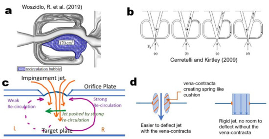
Figure 3.
Presence of backplate (orifice plate) creates asymmetric oscillating fluidic circuits [69,70] like (a) sweeping jet, (b) an array of oscillating jets, (c) jet oscillation due to re-circulation, and (d) spring-like cushion for the jet by vena-contracta [4] (courtesy: open access and ASME).
Among other things, researchers have tested inserts in jets as well. Ikhlaq et al. [71] numerically investigated a swirl insert inside the impingement orifice. This paper had an exhaustive list of papers related to swirl jets. The swirl jet performed worse with higher h/D = 6 as compared to a non-swirl jet with similar parameters, but the Nu increased with swirl at h/D = 2 and 4. The pressure and flow characteristics in a swirl jet were experimentally measured by Ahmed et al. [72], but no heat transfer measurements were reported. Markal [73] tried to create a swirling free jet with a spiral path around a round jet. It is doubtful that a swirl would persist after it was discharged from the spiral path. Most likely, the discharged jet had a dominant tangential velocity component rather than a rotating vortex. The swirl jet showed a wider radially affected region but did not improve the overall heat transfer coefficient. Markal et al. [74] studied a free concentric cone jet with a round jet in the middle. The performance dropped at 30° cone angle but showed better results with 20° when the jet was almost touching the target surface. It is not clear if the cone jet combination worked better as no direct comparison with the same mass flow and pressure drop were presented. A better swirl jet design was used by Ahmed et al. [72] by letting the flow enter the orifice from a side hole. They provided flow measurements, but no heat or mass transfer studies were conducted.
Limaye et al. [75] compared the impingement heat transfer from an orifice and convergent nozzle. The orifice showed better heat transfer and showed the lack of flow separation at the wall jet formation, as seen in a nozzle. This supports the hypothesis that the jet from an orifice is not steady due to the freedom provided by the vena contracta and that is better for the heat transfer enhancement. Muvvala et al. [76] experimentally studied a single square jet and cluster of square jets replacing the single-jet exit. The cluster of jets had higher exit velocity for the same mass flow rate and showed better heat transfer at the expense of a significant pressure drop. Notched orifice results with both flow visualization and heat transfer were presented by Shakouchi and Kito [77]. They observed higher turbulence on jet edges, more instability with small notches and lower pressure drop, most likely due to reduction in vena-contracta, and an increase in flow area as the notches were cut on top of the base circular orifice. The heat transfer improved by 2–3% for the same mass flow, and as a result, it would be very difficult to verify with experiments that have an uncertainty of 7% or higher. Since impingement has a high heat transfer coefficient, a small percentage improvement results in a large gain in the heat transfer coefficient. We had a similar experience with a star-notched orifice.
Heat transfer and fluid flow measurements on an unconfined jet were carried out by Ozmen and Baydar [78]. Ozmen and Ipek [79] studied an array of four slot jets with both numerical and experimental techniques with and without crossflow effects. Sodjavi et al. [80] experimentally observed that a hemispherical cross-shaped nozzle performed much better than a regular orifice jet. They had a single free jet configuration. The average improvement was more than 20% compared to a converging nozzle jet. Miller et al. [81] numerically studied the jet exit shapes: round, oval, square, rectangular, and triangular. Their work was aimed at combustion, and the jet flow had a co-flow from the surroundings. The jet diameter was also large at 2 cm. This detailed study on unsteady jet structures showed that jet spread was maximum with triangular exit, whereas the circular exit showed maximum core fluctuation, which is beneficial to heat transfer enhancement. Figure 4 shows the centerline velocity and jet velocity fluctuations with different orifice shapes. The round jet provided the best combination of jet velocity preservation with higher fluctuation levels. These characteristics are observed in heat transfer experiments, where round orifice usually outperforms other shapes due to better core velocity and higher core turbulence levels. A wide triangle shape shows the highest core velocity fluctuations, but it caused a faster decay in jet core velocity magnitude.
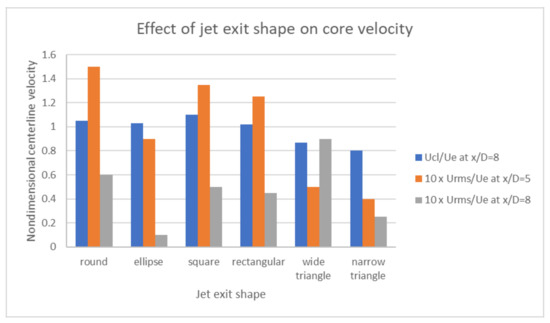
Figure 4.
Effect of six different jet exits on velocity distribution (data from [81]) [4].
Impingement is used in electronics cooling, and a review of microjet applications for smaller devices are available in Wei et al. [82]. They discussed micrometer hole sizes and complex structures with a spent jet collection system in the insert. A 4-by-4 nozzle array with 0.5 mm diameter holes with a jet-to-wall spacing of 0.4 mm created a heat transfer coefficient of 62.5 kW/m2K with a pumping power of 0.3 W. If clogging is not an issue or can be mitigated with occasional reverse flows, microjets can be an effective way to achieve very high heat transfer coefficients in an integrated structure without conventional impingement inserts. Dutta and Maldonado [83,84] created a scheme to clean the small cooling passages with occasional reverse flows through the passages. The reverse flow scheme is shown in Figure 5, where three-way valves were used to pressurize and de-pressurize the cooling channels with reverse flow. The clogged holes can be re-opened with the reverse flow, and some engines use water to clean the channels as well. Clogging of impingement holes can be a problem for large power generation turbines, and there is a system-level research opportunity on these heavy-duty turbines.

Figure 5.
Engine cleaning with reverse flow effect (comparable to sneezing) [83,84].
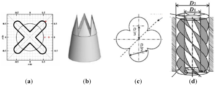
There have been several other investigations on jet impingement holes shapes. Figure 6 shows Nusselt number contours/flow visualization for different jet hole shapes. Unfortunately, these hole-shaped jets lose their shape and become round as the target distance is increased from the orifice plate. Published hole-shape based results are usually for orifices that are very close to the target plate and are not usable in a real engine situation. However, the racetrack shape provided beneficial improvement at a usable distance. Thin holes tend to clog easily and are avoided in real engine design.
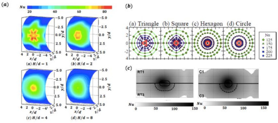
Figure 6.
Jet footprint with (a) chevron [85], (b) shaped jets [86], (c) racetrack, and cylindrical jet [16]. (courtesy: open access and ASME) [4].
3.3.1. Thermal-Hydraulic Performance of Shaped Jets
Heat exchanger designers strive for enhancement in thermal-hydraulic performance, i.e., enhancement in heat transfer is always viewed against the pumping power required to sustain such cooling levels. Thermal hydraulic performance (THP) is commonly used to rank cooling configurations for duct-type flows and is given by , where and are baseline Nusselt numbers and friction factors usually taken as the ones for smooth channels without any heat transfer enhancement features. However, in the case of impingement systems, such an analysis is usually rarely seen. To this end, in this paper, we suggest presenting the heat transfer coefficient with respect to the pumping power to rank the thermal-hydraulic performance for jet impingement concepts. Through this analysis, different jet hole shapes can be compared with respect to each other for their thermal-hydraulic performance. In most papers, the discharge coefficient () is provided, and with the additional knowledge of perimeter of jet () and physical area of jet (), the pumping power () can be calculated with Equation (1). As most of the past heat transfer data were focused on , this crucial pumping power information may not be available in some studies.
Heat transfer coefficient determination is rather simple, . The above analysis was carried out on the work of Singh et al. [63], and it was found that the heat transfer coefficient for V-shaped jets was 1.81 times that of round shaped jets; however, this gain in heat transfer was achieved at 2.58 times the pumping power cost compared to the round jets. This information was missing from their paper, which presented heat transfer and pumping power in normalized forms, which often masks the critical information required for the cost–benefit analysis. From the above analysis, one can argue that possibly the round shape impingement jets are better when all factors are accounted for—a conclusion that could not have been arrived at, through the discrete presentation of Cd and Nuj variation with Rej. Similarly, Jordan et al. [16] carried out an experimental investigation on heat transfer characteristics of racetrack and cylindrical jets where nozzle contouring effects were also explored. From the above analysis, the racetrack-shaped hole had ~48% higher convective heat transfer coefficient at ~37% increment in the pumping power requirement for the square orifice shape. Note that Jordan et al.’s test was carried out on a single jet and that Singh et al. used multiple jets for maximum crossflow condition with plenum chamber effect. There have been many other investigations on some exotic jet impingement hole shapes, e.g., chevron [23] and lobe [87], where the above analysis could not be carried out due to the absence of pressure drop or discharge coefficient data.
A summary of discharge coefficient and average Nusselt number from [16] is presented in Table 2.

Table 2.
Effect of orifice shape with the inclusion of pressure drop [16].
A similar analysis could be carried out on a series of sweeping jet impingement work, where the cooling performance is compared with a geometrically similar circular jet. Hossain et al. [88] investigated sweeping jets under different configurations using Infrared thermography and computational fluid dynamics to understand the heat transfer and fluid flow characteristics. The authors employed the sweeping jet under both flat and concave [89] targets applicable to the context of a turbine vane [90]. In general, it was found that the sweeping jets underperform compared to the circular jet.
3.3.2. Design Equivalency of Shaped Jets
Several investigations on orifice shapes have presented the heat transfer coefficient (or Nusselt number) versus Reynolds number. Unfortunately, Reynolds number is not a design parameter for a gas-turbine cooling engineer, whereas pressure drop (or pumping power) is the parameter of interest. For example, if we re-analyze the circular orifice jet’s heat transfer from a full fillet configuration to sharp-edged (data from Table 2), the final design outcome comes out to be more than the tabulated Nusselt number of 77. The actual design value is more like 82 and is explained in Figure 7.
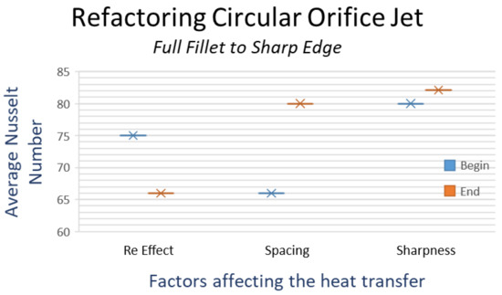
Figure 7.
Estimating the average Nu change to sharp-edged circular orifice based on full fillet circular orifice data.
Figure 7 shows the step-by-step accounting such as changes in heat transfer due to different configuration effects with given pressure drop. The first consideration is given to the Reynolds number. To keep the same flow rate with the same pressure drop, the jet diameter for a sharp-edged orifice will be larger, thus decreasing the average exit flow velocity and decreasing the Reynolds number for the sharp-edged orifice. The accounting plot is shown with the beginning as the full fillet Nusselt number from Table 2 and the drop accommodating in Nu from the Re effect. Since the throughput is the same and the hole configurations are maintained to be the same, with larger-diameter holes, the nondimensional spacings become smaller and that increases the average Nu as shown by the spacing adjustment step. For the same Reynolds number, the sharpness of the orifice influences the Nu, and that is applied on the third accounting step. This type of debit–credit analysis shows the effect of different components on the overall heat transfer, and the net result is that if the designer replaces full fillet circular orifices with flow-adjusted circular orifices with larger diameters, the new Nusselt number is 82 and not 77, as shown in the table. The results in the table are correct for the experimental conditions (which matched hydraulic diameters instead of pressure drop) and need to be adjusted for the actual design as explained here. The Nusselt number does not give the correct picture in this scenario. To a less attentive designer, a higher Nu implies higher heat flux removed for a given temperature boundary condition, but one should remember that it is the heat transfer coefficient and not the Nusselt number that determines the heat flux. Since the sharp-edged orifice is bigger with a larger hydraulic diameter, the heat transfer coefficient is lower, even if the Nu is higher as indicated in Figure 7. For this given configuration, the heat transfer coefficient with fillet is actually 11% higher than the sharp-edged hole, even if the Nu is higher for the sharp-edged holes. Additionally, this is caused by the diameter adjustments to maintain the same coolant flow with the same pressure differences.
Figure 7 showed the increase in Nu by changing the edge sharpness, and Figure 8 shows the reverse journey on how the roundness of edges should be accounted for. Figure 7 shows the journey from the given full fillet circular orifice to the estimate of a sharp circular orifice jet, whereas Figure 8 starts with a sharp-edged racetrack orifice to estimate the equivalent full fillet racetrack orifice. Since Nusselt number based on correlations varies proportionally to jet Re2/3 and s/D (s is jet-to-jet spacing and D is jet-orifice hydraulic diameter) independently, the inclusion of these two parameters is separated in two steps as indicated in these figures. Contributions from the sharpness effect are obtained with similar configurations as presented in Table 2. The refactoring plots show the relative effects of different parameters on the average Nu. First is the change in Re effect to keep the same mass flow rate but different jet hydraulic diameter. The second is the change in s/D by keeping a fixed spacing “s” and changing the hydraulic diameter. The last effect is from the orifice sharpness as measured with similar configurations. When the hole shape is changed from sharp to full fillet with the same pressure drop and the same mass flow by changing the hydraulic diameter, the full fillet Nu for the racetrack-shaped hole comes out to be 72 as opposed to 75 when the same Reynolds number is maintained. The difference in Nu in these two configurations is deceptive, as discussed before. When the hydraulic diameters are used to back-calculate the heat transfer coefficients, the sharp-edged racetrack is only 6% better in terms of heat transfer with the same coolant flow and the same pressure drop. When the accuracy of prediction desired is of the order of 5 °C in a thousand-degree C environment, all aspects of corrective actions should be addressed properly in the design process.
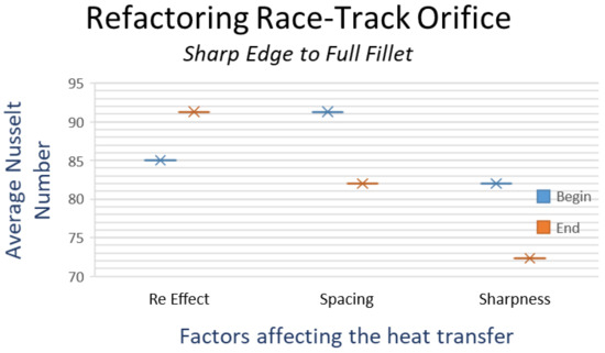
Figure 8.
Estimating the average Nu change from given sharp-edged racetrack orifice to rounded-edged racetrack orifice.
3.4. Backplate Modifications
The jet environment can be open or enclosed in a chamber. Baydar and Ozmen [91] observed flow characteristics of confined and unconfined air jets. The confinement was created with a backplate. Unfortunately, the jet setup had a streamline-tube-like exit, and therefore, the key flow observations that are argued in our paper were not produced. The streamlined jet fills the jet exit, and there is no large vena contracta. As a result, the jet does not move much with the recirculating air. Their paper did not give many new details but provided an important list of references.
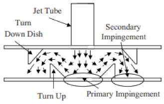
The backplate creates a return jet structure like a fluidic device. Bobusch et al. [92] studied the internal flow structure of a fluidic oscillator. This oscillator structure can be formed in a confined jet. The jet impinges on the target surface and then circulates back to the jet origination point in the presence of a backplate. As a result, the jet can be pushed to oscillate, and that increases heat transfer over a wider area as compared to a stable jet. Oscillation is stronger with a sharp-edged orifice because the jet is detached from the orifice surface due to vena contracta. A larger vena contracta provides more room for jet movement, and higher flow oscillations are expected. Jeffers et al. [25] proposed a turn-down dish = type modification for the backplate, which pushed the spent coolant towards the target wall. However, they used water as the working fluid, which has much more heat capacity to absorb thermal energy without significant changes in temperature. In air impingement, heat pickup of the spent jet is significant, and reuse of a spent jet may not be as effective.
The secondary vortex created by impingement with a backplate is argued to create three-dimensional unsteady fluidic-oscillation-like behavior. This can be a topic of exploration in flow visualization for oscillations in sharp-edged orifice discharge. Cerretelli and Kirtley [70] illustrated the use of fluidic oscillation in boundary-layer separation control. Their device fixed the diffuser boundary layer separation. This fluidic device worked without any moving parts and used a feedback flow from downstream of a jet to the origin of the jet. It caused jet oscillation that significantly disturbed the boundary layer where it was implemented. The same oscillation technique is perhaps inherently present in sharp-edged orifice with low Cd, which is created by vena-contracta, and that allowed the jet to move from one side to the other with a feedback push caused by secondary flow in a backplate confined impingement chamber.
The backplate causes entrainment of freestream fluid in the jet. Striegl and Diller [93] analytically observed the entrainment effect on a single jet. They observed that when thermal entrainment is included, a single jet model can be extended to widely spaced multiple jet observations. Figure 9 illustrates the insert surface modifications as proposed by the patents developed at GE. These 3D fin structures do not disturb the jet recirculation structure, yet cool the spent jet with a finned surface, enhancing the cooling performance of the mixed flow caused by entrainment.

Figure 9.
3D printing of inserts with fins [94,95] (courtesy: open access).
A review paper by Jambunathan et al. [96] illustrated the changes made to the entrainment by the backplate. They collected data published on 5000–124,000 jet Reynolds number and nozzle to plate gap of 1.2–16D. They suggested that correlations should include this jet-to-target plate spacing and not only depend on the exit Reynolds number. Figure 10 shows the tentative effect of heat transfer on the backplate, where Tf is post-impingement temperature and Ts is the target temperature which is estimated with Equations (2) and (3). The simple heat balance equations used for these temperature plots are:

Figure 10.
Jet and post-impingement temperatures as defined in the schematic [4].
The backplate was in contact with the spent jet, as illustrated in Figure 10, and can facilitate heat transfer from the spent jet to the incoming fresh coolant supply. At a low flow rate, calculations can wrongly predict the spent jet to be higher than the target surface temperature. This faulty estimate has been observed in industrial calculations, and can be easily overlooked by the designer. That is because the way these correlations are developed and proposed to be implemented, errors can creep in. This is especially noticeable where the spent jet flow is already hot and then the impingement correlation assumes heat transfer is with cold jet and thus feed more energy to the already hot crossflow raising its temperature beyond feasible limits. With higher insert heat transfer, the incoming jet can be preheated while the spent jet cools down. The net result indicated to be beneficial with enhanced heat transfer, but those data are proprietary and cannot be disclosed here. Unfortunately, prior experiments did not pay much attention to the insert heat transfer, and there is a need for such efforts to understand the itemized heat transfer. The overall heat transfer coefficient available from correlations do not pay much attention to the orifice plate itself, and we recognize this as an area of improvement.
Temperature increase calculated with conventional Nusselt numbers can provide an unreasonable outcome as the temperature difference used is that of the target surface and jet temperature. The actual cool jet comes in contact with the target in a small area. and most of the impingement area is actually cooled by the entrained jet flow. Figure 11 shows how the spent jet temperature increases rapidly with a single jet impingement. Presented calculations use Equations (2) and (3) to find post-impingement spent jet temperature. The target surface temperature is set at 1000 °C for illustration and the coolant erroneously went above the target surface temperature for some configurations. This has been observed in real engine design and the designer needs to check the spent jet temperature before using these calculations blindly on a component. The correlations used are taken from Martin’s single jet analysis [97,98]. The equations used are given in Equations (4) and (5). The Reynolds number is based on jet diameter, and the target surface area is defined by a limited radius. Results indicate a significant heat pickup by the cooling jet, and that hot spent jet becomes crossflow for the next impinging jet. Since there is a mixing of jet and spent jet, the mixed temperature of the next jet is significantly higher. If the spent jet is cooled by the backplate, the cooling performance increases. However, the current jet temperature will increase due to that backplate heat transfer. This interplay of the current jet and next crossflow affected jet are under investigation, and results will be provided when available.
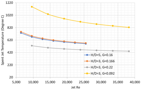
Figure 11.
Temperature increase in spent jet with target surface at 1000 °C and jet temperature at 300 °C.
3.5. Target Surface Modification
Experimental investigations on target surface modification have increased in the past decade. Takeishi et al. [99] used a circular rib in the wall jet region to enhance heat transfer. This location of the rib increased local heat transfer, but when averaged over the impingement surface, it provided mixed results. Rib location at R/D = 2.5 provided a 50% boost in the average heat transfer, but a location closer or further to rings decreased overall heat transfer. It is hard to position a jet with respect to features made on the target surface. Impingement inserts in stationary components are usually made out of sheet metal and then welded on the target surface, which is usually cast separately. An additive-manufacturing-based approach will potentially be able to integrate the insert with the target surface, but at the current state of technology, the precise location of ribs with respect to the jet location is hard to achieve.
Industrial designs use surface modifications on the impinged surfaces [100]. With the development of 2D heat transfer measurements, several studies were published on target surface modifications. There are too many surface modifications studies available than can be satisfactorily discussed in this paper, and hopefully, there are enough pointers provided here for further studies.
McInturff et al. [67] tested triangular surface roughness with different orifice shapes. Small triangles on the target surface increased heat transfer for round and racetrack holes. Surprisingly, the triangular holes showed better performance near stagnation but reduced heat transfer coefficient between jets with triangular surface roughness. Our experience with non-circular holes also indicated a drop in the heat transfer coefficient, and we hypothesize that the jet stability was the reason behind this observation. Triangular or deviation from sharp-edged orifice restricts the flexibility of the jet due to higher turbulence at the corners, and that made the jet stiffer to get affected by the recirculating flow and less fluidic oscillation. It is possible that the triangular orifice jet is stable but wider due to higher turbulence at the edges, which creates a thicker turbulent boundary layer on the target surface that submerged the triangular surface roughness. Flow visualization may help to answer this anomaly.
Figure 12 shows the target surface roughness used in real gas-turbine engines. These figures are extracted from a patent issued to GE and Rolls-Royce. There are micro and macro levels of surface modification, and these are usually formed while casting the component shell. The casting of surface bumps has its own issues, and some of the mitigation techniques are discussed in the GE Patent [101]. These surface modifications are applied in the real-world components, but maintenance and inspection of the quality of these castings can be difficult. Feedback from solid model designers developing the CAD models with these surface modifications indicates that it can be challenging to view and edit these solid models with thousands of bumps as these files become large, becoming unyielding and not suitable for design edits. If the design requires proper alignment of the hole with the surface modification, then it has additional uncertainty as the impingement sleeve and the cast surface are manufactured separately and alignment is not guaranteed during assembly or after several hot hours of operation.

Figure 12.
Target surface micro-bump and macro-contour [100,102] (courtesy: open access).
3.6. Impingement Channel Modification
High-porosity metal foams offer an exclusive advantage of near-zero jet-to-target spacing, which results in significantly higher heat transfer due to the combined action of jet impingement and extended surfaces. Singh et al. [103,104,105] carried out a series of investigations on the above topic. Experimental work used thin foams mounted onto the substrate. Several other investigations followed on this concept, where high-porosity and high pore-density thin aluminum and copper foams were used for jet impingement heat transfer enhancement [28,106,107]. One potential extension of this work can be the fouling of metal foams and its effect on the heat transfer especially for land-based large-scale turbines, that can have a significant amount of corrosion and oxidation (presence of oxidized powders) that foul film holes and impingement holes.
Madhavan et al. [106] used metal foam between the jet and the target plate to enhance impingement heat transfer. A marked increase in heat transfer coefficient was noted with a fully packed chamber. The heat transfer enhancement was nearly three times at an Re of 4000 in the given configuration. Thin strips of foam also enhanced heat transfer, but fully packed foam performed the best. Singh et al. [108] proposed a concept for enhancing channel flow heat transfer through a combined action of an array of jets introduced flushed with a metal foam block installed on the substrate subjected to heat load.
Jia et al. [109] numerically studied the effect of a rib-roughened surface in an impingement chamber with crossflow and found the ribs to be mostly ineffective. The ribs were placed directly under the slot jets or staggered from the jet. The presence of large ribs interfered with the impingement process and reduced the heat transfer compared to impingement on a smooth surface. Rao [110] used pin fin with jets on a target surface and experimentally studied the performance of full-length and miniature pins. The full-length pins increased heat transfer uniformity and performance by more than 30% with additional pressure loss, whereas miniature pins increased heat transfer rate by nearly 75% with low impact on the pressure drop. Unfortunately, pins mounted on a conductive backplate were not tested.
Surface modification and channel modification can overlap to some extent. If the surface modification is comparable to the impingement orifice size scale, the channel flow is affected by those surface modifications. Readers can look at liquid-crystal-based papers on dimpled, pin fin, mixed dimple, and pins to get more information. Transient heat transfer techniques are useful as they provide local details at a faster rate than steady-state tests [44]. Most two-dimensional heat transfer measurements assume the surface transient behavior is one-dimensional perpendicular to the surface direction. Ahmed et al. [111] found that for accurate measurement of transient heat transfer in impingement, a three-dimensional transient conduction analysis was necessary. They post-processed previously published observations and noted an increase in the peak heat transfer with multiple jet impingement. In general, heat transfer was enhanced by target surface modifications, but there are some configurations that showed a decrease in heat transfer with surface modifications, and users should keep that in mind. For example, Kanokjaruvijit and Marinez-Botas [112] found that a dimpled surface had worse performance than a smooth target when the jet to plate gap was small (h/D = 2). For higher gaps, the dimpled surface performed better than the smooth surface. The crossflow in that work was controlled by adjusting the number of surrounding walls in the impingement chamber.
3.7. Crossflow Regulation
Crossflow developed by spent jets is detrimental to impingement heat transfer because strong crossflow perpendicular to jets can deflect the impinging jets away from the target surface, reducing their effectiveness in cooling. Kercher and Tabakoff [51] tried to separate the single jet and multiple jet effects with two factors as shown in Figure 13. It looked logical, but a clear correlation cannot be achieved as of today. There is room for improvement on these composite or superposition effects.
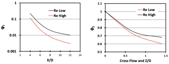
Figure 13.
Schematic of the two factors used by Kercher and Tabakoff [51].
Katti and Prabhu [113] repeated the configuration used by Florschuetz et al. [13]. The exit of their test setup was too close to the impingement chamber, and a bias towards a higher Nusselt number near the exit was observed. The spanwise distribution of 4d performed better than 2d and 6d.
Miao et al. [114] numerically investigated multiple jet impingement with different crossflow orientation. They studied both-sides-open (named as hybrid), and one-side-open channels as parallel and counter flow orientations relative to the supply chamber and impingement chamber. Hybrid channel configuration showed better performance with an inline jet arrangement. The peak difference was in the order of 20%. Ji et al. [115] varied jet diameters to compensate for the degradation caused by crossflow. Their numerical work used a 3 × 9 array of jets with five different hole size configurations. Gradually increasing jet diameter towards the crossflow exit showed a more uniform heat transfer coefficient.
Al-Hadhrami et al. [116,117] experimentally studied a 1.5° divergent channel to accommodate the spent jet and to reduce the crossflow effects. Both parallel and counter flow exits were considered. An impingement chamber with both ends open was also studied. The exit was too close to the impingement holes, and that affected the results—heat transfer was lower near the exits because the coolant escaped to the exit instead of impinging. Future experiment designers should pay attention to the exit length and the entry length of the impingement setup. The jet Re was varied from 9300 to 18,800, and in this range, the divergent channel did not show much improvement or mitigated the crossflow effects. The short exit lowered the heat transfer near the exit, and this is a lesson learned, because in a turbine component, at times, both the inlet and exit lengths are short or non-existent. In that scenario, it can be argued that a tube hole instead of an orifice hole will perform better to give impinging jets a direction towards the target plate near the inlet and exit.
An inclined wall seems to be an attractive option for researchers to test the reduced crossflow effects, as presented by Hebert et al. [118], but results were not conclusive and we do not recommend taking this approach. Both converging and diverging channels were tested and compared with parallel chambers. No clear winner was detected in these configurations. A recent development in the impingement is a pulsating jet. There is no guidance on how to create those pulses yet, but commercial fluidic applications such as garden blowers are developing technologies to pulsate the flow without moving parts. Tang et al. [119] and Lyu et al. [120] performed an experimental and numerical investigation of pulsating jets. They used frequencies between 5 to 40 Hz with a speaker and observed a higher heat transfer coefficient near the stagnation region. The affected zone with this pulsation was about 2 jet-diameters wide from the stagnation point. They used a single jet, but it seems that, by synchronizing the waves in different jet rows, a reduction in crossflow can be achieved. However, how difficult is that to implement is yet to be seen.
4. Forgotten Recovery Factor in Impingement
The recovery factor, r, is defined as [121]:
In compressible flow, the kinetic energy lost in the boundary layer is absorbed by the fluid, and as a result, the local fluid temperature increases [122]. In the ideal situation r = 1, all the lost kinetic energy is observed in the rise in local adiabatic wall temperature. In impingement, this can be measured for high flowrates near the target stagnation point. In an impingement, a recovery factor greater than 1 can be obtained at larger L/D (larger gap) due to entrainment of the surrounding hotter fluid. Explanation of values of r < 1 is more complex and is associated with high curvature flow cooling. Cooling by highspeed vortex is successfully implemented in commercial products such as vortex tubes [123]. This aspect of jet swirl cooling cannot be observed in the low-speed low-pressure test facilities. Imagine the hot gas outside of the airfoil is at 1000 °C and the coolant is supplied at 300 °C. As a simple thermal analysis, we can assume that the temperature range will be limited between 300 °C and 1000 °C. However, a high impact of the jet can create locally hotter air, as implied by Figure 14, effectively increasing the lower bound from 300 °C. The study by Goldstein et al. [121] showed that the compressibility effect of the jet increases the near-wall coolant temperature, and the heat transfer surface effectively never sees the 300 °C coolant; instead, the coolant temperature is higher, and that higher temperature is dependent on how fast the jet is moving. Usually, a higher jet velocity implies a higher near-wall coolant temperature, but the swirl cooling like in a vortex tube mechanism can drop the temperature as well. This recovery factor is more important in the second and later stages of gas turbines, where the pressure drop available between the supply side and dump side are high, thus causing higher flow velocities. In the first stage, the pressure difference between the supply and dump is low and becomes lower as the combustor design aims for a lower pressure drop. With a lower pressure difference across the orifice, the jet velocity is also low in stage-one stator components. Since adiabatic wall temperature does not change much from the jet temperature in low-speed, low-pressure plexiglass setups, experimentalists do not present this aspect of heat transfer in their correlations. The gas-turbine designer needs to keep this recovery factor in their calculations; otherwise, there is a possibility to overestimate the cooling capacity with neglected recovery temperature rise.
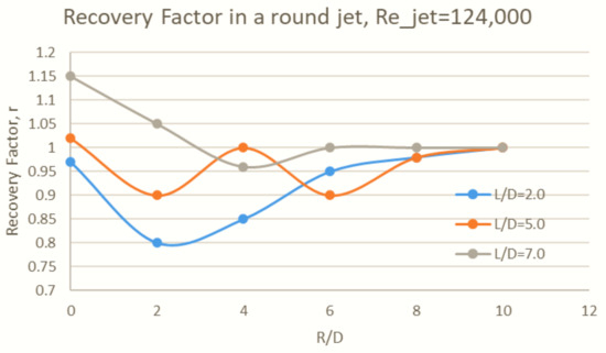
Figure 14.
Recovery factors as measured by Goldstein et al. [121].
5. Detailed Two-Dimensional Thermal Measurements
The above sections present various factors and concepts involved in jet impingement heat transfer with emphasis on some less explored ideas with some recommendations for novel concepts that could potentially yield an improved heat transfer performance. We also presented some views on how to analyze the obtained heat transfer results, along with the incurred concomitant pressure drop to determine the actual performance of a concept or design modification. In this section, we present another factor that plays a vital role in impingement heat transfer design, i.e., the adopted heat transfer measurement technique. Conventionally, the older impingement studies were primarily based on heated metal stripes where a known heat flux was applied and resultant wall temperature and fluid temperature were measured to obtain a regionally averaged value of convective heat transfer, e.g., [124]. This experimental method is robust in nature with a very small level of uncertainties (typically < 5%) and had a high degree of repeatability. However, this technique did not provide the information on local heat transfer characteristics of the impinging jets and the physics-based explanations were mostly limited to classical boundary layer flow analysis. Jet impingement heat transfer is typically associated with regions of very high and very low heat transfer, which also leads to high thermal stress on the target walls to be cooled, and this is an undesirable phenomenon for hot gas path component lifetime. Further, much of the research carried out on jet hole shape modification and plenum chamber modification requires the knowledge of resultant local changes in the heat transfer characteristics on the target wall, which could drive the design iterations. To this end, detailed two-dimensional measurements are imperative to enhance our understanding of local heat transfer. Two popular thermal diagnostic techniques, viz., liquid-crystal and infrared thermography are widely employed by the turbine heat transfer community. These techniques, however, may vary based on the nature of heat transfer experiments, whether they are transient or steady-state in nature. The transient experiments are typically conducted by allowing heated or cooled air on a solid surface made from low thermal conductivity and low thermal diffusivity material, which can be treated as a semi-infinite transient medium during the short duration test runs and the heat diffusion into the solid is assumed to be perpendicular and one-dimensional. These techniques yield high-resolution and sharp two-dimensional contours of convective heat transfer coefficients, which designers can use to design the placement of jets and locally vary jet sizes for different spent air exit schemes. A sample image for a moderate crossflow scheme is shown in Figure 15.

Figure 15.
Local map of convective heat transfer coefficient for moderate crossflow scheme [61], with permission to reuse from Elsevier.
It can be observed from Figure 15 that there exists a strong gradient in convective heat transfer coefficient from the jet stagnation, and the space between two adjacent jets can have low heat transfer zones. Such a distribution can potentially lead to large variations in local temperatures, which in turn lead to high levels of thermal stresses. The authors in [61] also investigated heat transfer characteristics when effusion holes were placed in the low-heat-transfer regions, with an intention to encourage coolant flow to the low-heat-transfer regions, and moreover to provide an exit path for the spent jet air. Extraction of spent jets through effusion holes led to a reduced effect of crossflow on the jet rows placed near the channel exits. The addition of surface microchannels can reduce the thermal stresses in combination with impingement and effusion cooling.
6. Conclusions
This review article on impingement cooling technology is aimed towards identifying future growth areas in impingement heat transfer analysis. Some of the existing data are re-analyzed and presented with a different viewpoint. Based on the observations and extrapolated analyses, we have explained a few interesting phenomena that have not been reported before. The following research opportunities for future work are identified from our analysis:
- Separation of crossflow and entrainment effects: Simulate crossflow at room temperature at the entrance of the impingement chamber with forced channel flow; this will have the jet deflection effect but will not have the entrainment of spent jet temperatures. After that, vary the starting crossflow temperature to study the entrainment effects in multiple or single rows of jets. Does it match post-impingement crossflow thermal data? If not, something more than just the flow and temperature needs to be added such as skewness in the flow field and turbulence.
- Evaluate high-performance orifices at a fixed pumping power: Compare data in terms of raw heat transfer coefficient for a given flow rate at a given pressure drop, and not in terms of Nusselt number as nondimensional information masks the true enhancement levels. Prior investigations in this area have not looked at the heat transfer with the concomitant pressure drop. We understand the use of Nu and Re for extrapolating the usable range of experimental data, but to compare the real impact with the same design constraints, raw heat transfer coefficient with a matched pressure drop provides a better understanding.
- Identification of more suitable nondimensional test parameters: Include hole discharge effect along with the hole size. There is perhaps a different nondimensional parameter than the current Reynolds number because Re defined with hole diameter does not include the Cd effect, which effectively reduces the exit diameter of a jet. This new form of jet Reynolds number, when proposed, should be easy enough to be applied in commercial design. Furthermore, the definition of heat transfer coefficient involving a far-field reference temperature should be revisited. The adiabatic wall temperature is perhaps a more suitable option; however, it is not directly measured in transient heat transfer experiments.
- Fluidic oscillation in low Cd orifice flows with backplate: Add flow oscillations (not axial pulsation) with fluidic devices. The trend in published literature shows that lower Cd is better for impingement heat transfer, but no explanation on the cause has been found yet. A possible explanation of jet oscillation with low Cd orifice is illustrated in this work and perhaps can be verified with detailed experimental unsteady measurements. Fast-changing unsteady heat transfer experiments are difficult to design, which is perhaps why this aspect has not yet been tested. Can the orifice jet heat transfer pattern be reproduced by mechanically oscillating a tube jet? If so, what is the frequency and amplitude of the oscillation?
- Mach number, swirl, and recovery effects on impingement: Use high-velocity compressible flow tests. The high Mach flow with compressibility effects needs to be investigated to simulate real engine conditions as those data are not available in the public literature. Most of the benchmark work done in the 1970s and 1980s was performed in near-atmospheric conditions. Since the experimental facilities and numerical tools have improved significantly, it will be interesting to observe jet impingement with compressibility effects. Impingement tests in low-pressure, low-flow environments cannot simulate recovery factor effects, but real engine operating conditions are extreme. Recovery heating and swirl cooling can play significant roles in engine condition heat transfer performance.
- Local tube jet instead of orifice jet when inlet or exit is close to the impingement chamber: Use tubes instead of orifices where the jet direction is important. The proximity of the channel exit with respect to the last row of jets affects the flow but has not been studied in detail. The proximity of the spent jet that exits near the last row of holes can facilitate additional discharge by suction from the holes near the exit and cause non-uniform jet distribution. It is also noticed that tube jets would have more directionality to penetrate the crossflow than orifice jets. Moreover, the tube length can be controlled to match the pressure losses created by non-uniform flow distribution and perhaps can be optimized. However, the region with lower crossflow should have sharp-edged orifices as they perform better than tube jets in that flow domain.
- Surface microchannels, heat pipes, and effusion cooling: Use surface microchannels with effusion cooling to reduce temperature gradients and cracking. Impingement cooling creates high temperature gradients and can cause cracking in components. To smoothen the thermal gradients, surface microchannels can be adopted along with effusion cooling. Back in 1995 [125], there were discussions on applying heat pipe in turbine structures by a division of DOE to help with the thermal loads, but it has not received a warm welcome from the turbine community. Maybe it is time to revisit that concept as well.
Author Contributions
Both authors have contributed equally to write, prepare, and develop this paper. The conceptual structure was primarily initiated by Dutta from his industrial experiences. Whereas, Singh took the lead on elaboration of ideas based on his experimental and analytical work. Singh collected most of the supporting materials. All authors have read and agreed to the published version of the manuscript.
Funding
This research received no external funding.
Institutional Review Board Statement
Not applicable.
Informed Consent Statement
Not applicable.
Data Availability Statement
Not applicable.
Acknowledgments
This work is a followup of our publication at the ASME Turbo Expo 2021: Paper No. GT2021-59394. Permission from ASME to use partial text and some figures is gratefully acknowledged.
Conflicts of Interest
The authors declare no conflict of interest.
References
- Han, J.-C.; Dutta, S.; Ekkad, S. Gas Turbine Heat Transfer and Cooling Technology, 2nd ed.; CRC Press: New York, NY, USA, 2012. [Google Scholar] [CrossRef]
- Bunker, R.S.; Dees, J.E.; Palafox, P. Impingement cooling in gas turbines: Design, applications, and limitations. In Flow Phenomena in Nature; WIT Press: Southampton, UK, 2014; Volume 2, pp. 1–32. [Google Scholar]
- Amano, R.S.; Sunden, B. Impingement Jet Cooling in Gas Turbines; WIT Press: Southampton, UK, 2014. [Google Scholar]
- Dutta, S.; Singh, P. Impingement heat transfer innovations and enhancements: A Discussion on selected geometrical features. In Proceedings of the ASME Conference, Online, 11–17 June 2021. [Google Scholar]
- Han, B.; Goldstein, R.J. Jet-impingement heat transfer in gas turbine systems. Ann. N. Y. Acad. Sci. 2006, 934, 147–161. [Google Scholar] [CrossRef]
- Obot, N.T.; Trabold, T. Impingement heat transfer within arrays of circular jets: Part 1—Effects of minimum, intermediate, and complete crossflow for small and large spacings. J. Heat Transf. 1987, 109, 872–879. [Google Scholar] [CrossRef]
- Shukla, A.; Dewan, A. Flow and thermal characteristics of jet impingement: Comprehensive review. Int. J. Heat Technol. 2017, 35, 153–166. [Google Scholar] [CrossRef]
- Culun, P.; Celik, N.; Pihtili, K. Effects of design parameters on a multi jet impinging heat transfer. Alex. Eng. J. 2018, 57, 4255–4266. [Google Scholar] [CrossRef]
- Baydar, E. Confined impinging air jet at low Reynolds numbers. Exp. Therm. Fluid Sci. 1999, 19, 27–33. [Google Scholar] [CrossRef]
- Zukowski, M. Heat transfer performance of a confined single slot jet of air impinging on a flat surface. Int. J. Heat Mass Transf. 2013, 57, 484–490. [Google Scholar] [CrossRef]
- Florschuetz, L.W.; Metzger, D.E.; Su, C.C. Heat transfer characteristics for jet array impingement with initial crossflow. J. Heat Transf. 1984, 106, 34–41. [Google Scholar] [CrossRef]
- Tong, A.Y. On the impingement heat transfer of an oblique free surface plane jet. Int. J. Heat Mass Transf. 2003, 46, 2077–2085. [Google Scholar] [CrossRef]
- Florschuetz, L.W.; Metzger, D.E.; Takeuchi, D.I.; Berry, R.A. Multiple Jet Impingement Heat Transfer Characteristic—Experimental Investigation of In-Line and Staggered Arrays with Crossflow; Contractor Report #3217; NASA Lewis Research Center: Cleveland, OH, USA, 1980. [Google Scholar]
- Esposito, E.I.; Ekkad, S.V.; Kim, Y.; Dutta, P. Novel jet impingement cooling geometry for combustor liner backside cooling. J. Therm. Sci. Eng. Appl. 2009, 1, 021001. [Google Scholar] [CrossRef]
- Terzis, A.; Ott, P.; Cochet, M.; Von Wolfersdorf, J.; Weigand, B. Effect of varying jet diameter on the heat transfer distributions of narrow impingement channels. J. Turbomach. 2014, 137, 021004. [Google Scholar] [CrossRef]
- Jordan, C.N.; Wright, L.M.; Crites, D.C. Impingement heat transfer on a cylindrical, concave surface with varying jet geometries. ASME J. Heat Transf. 2016, 138. [Google Scholar] [CrossRef]
- Lee, J.; Lee, S.-J. The effect of nozzle aspect ratio on stagnation region heat transfer characteristics of elliptic impinging jet. Int. J. Heat Mass Transf. 2000, 43, 555–575. [Google Scholar] [CrossRef]
- Singh, P.; Zhang, M.; Ahmed, S.; Ramakrishnan, K.R.; Ekkad, S. Effect of micro-roughness shapes on jet impingement heat transfer and fin-effectiveness. Int. J. Heat Mass Transf. 2019, 132, 80–95. [Google Scholar] [CrossRef]
- Weigand, B.; Spring, S. Multiple jet impingement—A review. Proc. Int. Symp. Heat Transf. Gas Turbine Syst. 2009, 42, 1–36. [Google Scholar] [CrossRef][Green Version]
- Cho, H.H.; Kim, B.S. Impingement/effusion cooling methods in gas turbine. Flow Phenom. Nat. 2014, 76, 125–155. [Google Scholar] [CrossRef]
- Yamane, Y.; Yamamoto, M.; Motosuke, M.; Honami, S. Effect of jet shape of square array of multi-impinging jets on heat transfer. In Proceedings of the ASME GT2013-94452, San Antonio, TX, USA, 3–7 June 2013. [Google Scholar]
- Kristiawan, M.; Meslem, A.; Nastase, I.; Sobolik, V. Wall shear rates and mass transfer in impinging jets: Comparison of circular convergent and cross-shaped orifice nozzles. Int. J. Heat Mass Transf. 2012, 55, 282–293. [Google Scholar] [CrossRef]
- Violato, D.; Ianiro, A.; Cardone, G.; Scarano, F. Three-dimensional vortex dynamics and convective heat transfer in circular and chevron impinging jets. Int. J. Heat Fluid Flow 2012, 37, 22–36. [Google Scholar] [CrossRef]
- Yang, H.; Kim, T.; Lu, T.; Ichimiya, K. Flow structure, wall pressure and heat transfer characteristics of impinging annular jet with/without steady swirling. Int. J. Heat Mass Transf. 2010, 53, 4092–4100. [Google Scholar] [CrossRef]
- Jeffers, N.M.R.; Punch, J.; Walsh, E.J.; McLean, M. Heat transfer from novel target surface structures to a normally impinging, submerged and confined water jet. J. Therm. Sci. Eng. Appl. 2009, 1, 031001. [Google Scholar] [CrossRef]
- El-Gabry, L.A.; Kaminski, D.A. Experimental investigation of local heat transfer distribution on smooth and roughened surfaces under an array of angled impinging jets. J. Turbomach. 2004, 127, 532–544. [Google Scholar] [CrossRef]
- Moreno, G.; Narumanchi, S.; Venson, T.; Bennion, K. Microstructured surfaces for single-phase jet impingement heat transfer enhancement. J. Therm. Sci. Eng. Appl. 2013, 5, 031004. [Google Scholar] [CrossRef]
- Sambamurthy, V.S.; Madhavan, S.; Singh, P.; Ekkad, S.V. Array jet impingement on high porosity thin metal foams: Effect of foam height, pore-density and spent air crossflow scheme on flow distribution and heat transfer. ASME J. Heat Transf. 2020, 142. [Google Scholar] [CrossRef]
- Madhavan, S.; Ramakrishnan, K.R.; Singh, P.; Ekkad, S.V. Jet impingement heat transfer enhancement by u-shaped crossflow diverters. J. Therm. Sci. Eng. Appl. 2019, 12, 1–15. [Google Scholar] [CrossRef]
- Chi, Z.; Liu, H.; Zang, S. Geometrical optimization of nonuniform impingement cooling structure with variable-diameter jet holes. Int. J. Heat Mass Transf. 2017, 108, 549–560. [Google Scholar] [CrossRef]
- Hollworth, B.R.; Wilson, S.I. Entrainment effects on impingement heat transfer: Part I—Measurements of heated jet velocity and temperature distributions and recovery temperatures on target surface. J. Heat Transf. 1984, 106, 797–803. [Google Scholar] [CrossRef]
- Hollworth, B.R.; Gero, L.R. Entrainment effects on impingement heat transfer: Part II—Local heat transfer measurements. J. Heat Transf. 1985, 107, 910–915. [Google Scholar] [CrossRef]
- Baughn, J.W.; Hechanova, A.E.; Yan, X. An experimental study of entrainment effects on the heat transfer from a flat surface to a heated circular impinging Jet. J. Heat Transf. 1991, 113, 1023–1025. [Google Scholar] [CrossRef]
- Immarigeon, A.; Hassan, I. An advanced impingement/film cooling scheme for gas turbines—Numerical study. Int. J. Numer. Methods Heat Fluid Flow 2006, 16, 470–493. [Google Scholar] [CrossRef]
- Mensch, A.; Thole, K.A. Overall effectiveness of a blade endwall with jet impingement and film cooling. J. Eng. Gas Turbines Power 2013, 136, 031901. [Google Scholar] [CrossRef]
- Mousavi, S.M.; Rahnama, S.M. Shape optimization of impingement and film cooling holes on a flat plate using a feedfor-ward ANN and GA. Energy Equip. Sys. 2018, 6, 247–259. [Google Scholar]
- Dutta, S.; Smith, R. Transfer function based optimization of film hole sizes with conjugate heat transfer analysis. In Proceedings of the ASME Turbo-Expo GT2020-14137, Virtual On-Line, 21–25 September 2020. [Google Scholar] [CrossRef]
- Dutta, S.; Smith, R. Nonlinear optimization of turbine conjugate heat transfer with iterative machine learning and training sample replacement. Energies 2020, 13, 4587. [Google Scholar] [CrossRef]
- Smith, R.; Dutta, S. Conjugate thermal optimization with unsupervised machine learning. J. Heat Transf. 2021, 143, 052901. [Google Scholar] [CrossRef]
- Issac, J.; Singh, D.; Kango, S. Experimental and numerical investigation of heat transfer characteristics of jet impingement on a flat plate. Heat Mass Transf. 2020, 56, 531–546. [Google Scholar] [CrossRef]
- Katti, V.V.; Yasaswy, S.N.; Prabhu, S.V. Local heat transfer distribution between smooth flat surface and impinging air jet from a circular nozzle at low Reynolds numbers. Heat Mass Transf. 2011, 47, 237–244. [Google Scholar] [CrossRef]
- Jeffers, N.; Stafford, J.; Conway, C.; Punch, J.; Walsh, E. The influence of the stagnation zone on the fluid dynamics at the nozzle exit of a confined and submerged impinging jet. Exp. Fluids 2016, 57, 1–15. [Google Scholar] [CrossRef]
- Li, W.; Xu, M.; Ren, J.; Jiang, H. Experimental investigation of local and average heat transfer coefficients under an inline impinging jet array, including jets with low impingement distance and inclined angle. J. Heat Transf. 2016, 139, 012201. [Google Scholar] [CrossRef]
- Ekkad, S.V.; Han, J.-C. A transient liquid crystal thermography technique for gas turbine heat transfer measurements. Meas. Sci. Technol. 2000, 11, 957–968. [Google Scholar] [CrossRef]
- Kaçar, E.N.; Erbay, L.B. Numerical Characterization of a Jet Impingement Cooling System Using Coupled Heat Transfer Analysis, ASME Turbo-Expo GT2015-43371. Montreal, QC, Canada, 15–19 June 2015.
- Zuckerman, N.; Lior, N. Jet impingement heat transfer: Physics, correlations, and numerical modeling. Adv. Heat Transf. 2006, 39, 565–631. [Google Scholar] [CrossRef]
- Zu, Y.Q.; Yan, Y.Y.; Maltson, J. Numerical study on stagnation point heat transfer by jet impingement in a confined narrow gap. J. Heat Transf. 2009, 131. [Google Scholar] [CrossRef]
- Williams, R.P.; Dyson, T.E.; Bogard, D.G.; Bradshaw, S.D. Sensitivity of the overall effectiveness to film cooling and internal cooling on a turbine vane suction side. J. Turbomach. 2013, 136, 031006. [Google Scholar] [CrossRef]
- Behbahani, A.I.; Goldstein, R.J. Local heat transfer to staggered arrays of impinging circular air jets. J. Eng. Power 1983, 105, 354–360. [Google Scholar] [CrossRef]
- Florschuetz, L.W.; Truman, C.R.; Metzger, D.E. Streamwise flow and heat transfer distributions for jet array impingement with crossflow. J. Heat Transf. 1981, 103, 337–342. [Google Scholar] [CrossRef]
- Kercher, D.M.; Tabakoff, W. Heat Transfer by a square array of round air jets impinging perpendicular to a flat surface including the effect of spent air. J. Eng. Power 1970, 73–82. [Google Scholar] [CrossRef]
- Team CCJ. Turbine Blade, Vane Cooling—A Primer. 2018. Available online: https://www.ccj-online.com/turbine-blade-vane-cooling-a-primer/ (accessed on 18 September 2021).
- Esposito, E. Jet impingement cooling configurations for gas turbine combustion. Master Thesis, Louisiana State University, Baton Rouge, LA, USA, 2006. [Google Scholar]
- Kratz, J.L.; Chapman, J.W.; Guo, T.-H. A Parametric Study of Actuator Requirements for Active Turbine Tip Clearance Control of a Modern High Bypass Turbofan Engine. In Proceedings of the ASME Turbo Expo, Charlotte, NC, USA, 26–30 June 2017. [Google Scholar]
- Liu, H.; Liu, C.; Wu, W. Numerical investigation on the flow structures in a narrow confined channel with staggered jet array arrangement. Chin. J. Aeronaut. 2015, 28, 1616–1628. [Google Scholar] [CrossRef]
- Oxford Thermofluid Institute, Turbine Cooling Group. Available online: https://oti.eng.ox.ac.uk/research-groups/turbine-cooling-group/ (accessed on 18 September 2021).
- Ekkad, S.V.; Huang, Y.; Han, J.-C. Detailed heat transfer distributions in two-pass square channels with rib turbulators and bleed holes. Int. J. Heat Mass Transf. 1998, 41, 3781–3791. [Google Scholar] [CrossRef]
- Wei-Hua, Y.; Jun, C.; Rui, S.; Xu-Sheng, H.; Shuang-Wen, S. Experimental investigation on impingement-effusion film-cooling behaviors in curve section. Acta Astronaut. 2011, 68, 1782–1789. [Google Scholar] [CrossRef]
- Kim, K.M.; Moon, H.; Park, J.S.; Cho, H.H. Optimal design of impinging jets in an impingement/effusion cooling system. Energy 2014, 66, 839–848. [Google Scholar] [CrossRef]
- Zhou, J.; Wang, X.; Li, J.; Li, Y. Effects of film cooling hole locations on flow and heat transfer characteristics of impingement/effusion cooling at turbine blade leading edge. Int. J. Heat Mass 2018, 126, 192–205. [Google Scholar] [CrossRef]
- Singh, P.; Ekkad, S.V. Effects of spent air removal scheme on internal-side heat transfer in an impingement-effusion system at low jet-to-target plate spacing. Int. J. Heat Mass Transf. 2017, 108, 998–1010. [Google Scholar] [CrossRef]
- Haneda, Y.; Souma, A.; Kurasawa, H.; Iio, S.; Ikeda, T. Enhancement of impinging jet heat transfer using two parallel confining plates mounted near rectangular nozzle exit. J. Fluids 2014, 2014, 1–11. [Google Scholar] [CrossRef]
- Singh, P.; Ravi, B.V.; Ekkad, S. Experimental investigation of heat transfer augmentation by different jet impingement hole shapes under maximum crossflow. In Proceedings of the ASME Turbo Expo, Seoul, Korea, 13–17 June 2016. [Google Scholar]
- Etemoglu, A.B.; Isman, M.K.; Can, M. Investigation into the effect of nozzle shape on the nozzle discharge coefficient and heat and mass transfer characteristics of impinging air jets. Heat Mass Transf. 2010, 46, 1395–1410. [Google Scholar] [CrossRef]
- Etemoglu, A.B.; Can, M. Performance studies of energy consumption for single and multiple nozzle systems under impinging air jets. Heat Mass Transf. 2013, 49, 1057–1070. [Google Scholar] [CrossRef]
- Goodro, M.; Ligrani, P.; Fox, M.; Moon, H.-K. Mach Number, Reynolds Number, Jet Spacing Variations: Full Array of Im-pinging jets. J. Thermophys. Heat Transf. 2010, 24, 133–144. [Google Scholar] [CrossRef]
- McInturff, P.; Suzuki, M.; Ligrani, P.; Nakamata, C.; Lee, D.H. Effects of hole shape on impingement jet array heat transfer with small-scale, target surface triangle roughness. Int. J. Heat Mass Transf. 2018, 127, 585–597. [Google Scholar] [CrossRef]
- Hsu, C.M.; Jhan, W.C.; Chang, Y.Y. Flow and heat transfer characteristics of a pulsed jet impinging on a flat plate. Heat Mass Transf. 2020, 56, 143–160. [Google Scholar] [CrossRef]
- Woszidlo, R.; Ostermann, F.; Schmidt, H.-J. Fundamental properties of fluidic oscillators for flow control applications. AIAA J. 2019, 57, 978–992. [Google Scholar] [CrossRef]
- Cerretelli, C.; Kirtley, K. Boundary layer separation control with fluidic oscillators. J. Turbomach. 2009, 131, 041001. [Google Scholar] [CrossRef]
- Ikhlaq, M.; Al-abdeli, Y.M.; Khiadani, M. Nozzle exit conditions and the heat transfer in non-swirling and weakly swirling turbulent impinging jets. Heat Mass Transf. 2020, 56, 269–290. [Google Scholar] [CrossRef]
- Ahmed, Z.U.; Al-abdeli, Y.; Guzzomi, F.G. Impingement pressure characteristics of swirling and non-swirling turbulent jets. Exp. Therm. Fluid Sci. 2015, 68, 722–732. [Google Scholar] [CrossRef]
- Markal, B. The effect of total flowrate on the cooling performance of swirling coaxial impinging jets. Heat Mass Transf. 2019, 55, 3275–3288. [Google Scholar] [CrossRef]
- Markal, B.; Avci, M.; Aydin, O. Conical coaxial impinging air jets: Angle effect on the heat transfer performance. Heat Mass Transf. 2020, 56, 3135–3146. [Google Scholar] [CrossRef]
- Limaye, M.D.; Vedula, R.P.; Prabhu, S.V. Comparison of heat transfer distributions on a flat plate impinged by under-expanded jets from a convergent nozzle and a circular orifice. Heat Mass Transf. 2012, 49, 309–326. [Google Scholar] [CrossRef]
- Muvvala, P.; Balaji, C.; Venkateshan, S.P. Experimental investigation on heat transfer from square jets issuing from perforated nozzles. Heat Mass Transf. 2017, 53, 2363–2375. [Google Scholar] [CrossRef]
- Shakouchi, T.; Kito, M. Heat transfer enhancement of impinging jet by notched—Orifice nozzle. In An Overview of Heat Transfer Phenomena; InTech: London, UK, 2012. [Google Scholar]
- Ozmen, Y.; Baydar, E. Flow structure and heat transfer characteristics of an unconfined impinging air jet at high jet Reynolds numbers. Heat Mass Transf. 2008, 44, 1315–1322. [Google Scholar] [CrossRef]
- Ozmen, Y.; Ipek, G. Investigation of flow structure and heat transfer characteristics in an array of impinging slot jets. Heat Mass Transf. 2016, 52, 773–787. [Google Scholar] [CrossRef]
- Sodjavi, K.; Montagné, B.; Bragança, P.; Meslem, A.; Bode, F.; Kristiawan, M. Impinging cross-shaped submerged jet on a flat plate: A comparison of plane and hemispherical orifice nozzles. Meccanica 2015, 50, 2927–2947. [Google Scholar] [CrossRef]
- Miller, R.; Madnia, C.; Givi, P. Numerical simulation of non-circular jets. Comput. Fluids 1995, 24, 1–25. [Google Scholar] [CrossRef]
- Wei, T.; Oprins, H.; Cherman, V.; Qian, J.; De Wolf, I.; Beyne, E.; Baelmans, M. High-efficiency polymer-based direct multi-jet impingement cooling solution for high-power devices. IEEE Trans. Power Electron. 2018, 34, 6601–6612. [Google Scholar] [CrossRef]
- Maldonado, J.J.; Dutta, S. System and Method for Operating a Gas Turbine Engine. U.S. Patent 9,206,744 B2, 8 December 2015. [Google Scholar]
- Dutta, S. Maldonado, J.J. Systems and Methods for Reconditioning Turbine Engines in Power Generation Systems. U.S. Patent 9,260,968 B2, 16 February 2016. [Google Scholar]
- Lyu, Y.; Zhang, J.; Liu, X.; Shan, Y. Experimental study of single-row chevron-jet impingement heat transfer on concave surfaces with different curvatures. Chin. J. Aeronaut. 2019, 32, 2275–2285. [Google Scholar] [CrossRef]
- Kanamori, A.; Hiwada, M.; Oyakawa, K.; Senaha, I. Effect of orifice shape on flow behavior and impingement heat transfer. Open Transp. Phenom. J. 2011, 3. [Google Scholar] [CrossRef]
- Martin, R.H.; Buchlin, J. Jet impingement heat transfer from lobed nozzles. Int. J. Therm. Sci. 2011, 50, 1199–1206. [Google Scholar] [CrossRef]
- Agricola, L.; Prenter, R.; Lundgreen, R.; Hossain, M.; Ameri, A.; Gregory, J.; Bons, J. Impinging sweeping jet heat transfer. In Proceedings of the 53rd AIAA/SAE/ASEE Joint Propulsion Conference; American Institute of Aeronautics and Astronautics, Atlanta, GA, USA, 10–12 July 2017. [Google Scholar]
- Hossain, M.A.; Agricola, L.; Ameri, A.; Gregory, J.W.; Bons, J.P. Effects of curvature on the performance of sweeping jet impingement heat transfer. In Proceedings of the 2018 AIAA Aerospace Sciences Meeting, Kissimmee, FL, USA, 8–12 January 2018. [Google Scholar]
- Hossain, M.A.; Agricola, L.; Ameri, A.; Gregory, J.W.; Bons, J.P. Sweeping jet impingement heat transfer on a simulated turbine vane leading edge. J. Glob. Power Propuls. Soc. 2018, 2, 5A7OAZ. [Google Scholar] [CrossRef]
- Baydar, E.; Ozmen, Y. An experimental investigation on flow structures of confined and unconfined impinging air jets. Heat Mass Transf. 2006, 42, 338–346. [Google Scholar] [CrossRef]
- Bobusch, B.C.; Woszidlo, R.; Bergada, J.M.; Nayeri, C.N.; Paschereit, C.O. Experimental study of the internal flow structures inside a fluidic oscillator. Exp. Fluids 2013, 54, 1–12. [Google Scholar] [CrossRef]
- Striegl, S.A.; Diller, T.E. An analysis of the effect of entrainment temperature on jet impingement heat transfer. J. Heat Transf. 1984, 106, 804–810. [Google Scholar] [CrossRef]
- Dutta, S.; Weber, J.A.; Lacy, B.P. Impingement Insert. U.S. Patent 10,494,948 B2, 3 December 2019. Available online: https://patents.google.com/patent/US10494948B2/en (accessed on 8 March 2020).
- Dutta, S.; Lacy, B.P.; Itzel, G.M.; Snider, Z.J. Impingement Insert for a Gas Turbine Engine. U.S. Patent 20, 180, 149,028 A1, 31 May 2018. Available online: https://patents.google.com/patent/US20180149028A1/en (accessed on 8 March 2020).
- Jambunathan, K.; Lai, E.; Moss, M.; Button, B. A review of heat transfer data for single circular jet impingement. Int. J. Heat Fluid Flow 1992, 13, 106–115. [Google Scholar] [CrossRef]
- Martin, H. Heat and mass transfer between impinging gas jets and solid surfaces. Adv. Heat Transf. 1977, 13, 1–60. [Google Scholar] [CrossRef]
- Bergman, T.; Lavine, A.S. Fundamentals of Heat and Mass Transfer, 8th ed.; John Wiley and Sons, Inc.: Hoboken, NJ, USA, 2017. [Google Scholar]
- Takeishi, K.-I.; Krewinkel, R.; Oda, Y.; Ichikawa, Y. Heat transfer enhancement of impingement cooling by adopting circular-ribs or vortex generators in the wall jet region of a round impingement jet. Int. J. Turbomach. Propuls. Power 2020, 5, 17. [Google Scholar] [CrossRef]
- Chiu, R.-S.P.; Hasz, W.C.; Johnson, R.A.; Lee, C.-P.; Abuaf, N. Enhanced Heat Transfer Surface for Cast-in-Bump-Covered Cooling Surfaces and Methods of Enhancing Heat Transfer. U.S. Patent 6,402,464 B1, 1 January 2002. Available online: https://www.osti.gov/servlets/purl/874499 (accessed on 9 October 2021).
- Johnson, R.A.; Schaeffer, J.C.; Lee, C.-P.; Abuaf, N. Method of Salvaging Castings with Defective Cast Cooling Bumps. U.S. Patent 2002/0,150,672 A1, 1 January 2002. [Google Scholar]
- Dailey, G.M.; Son, C.S. Air Impingement Cooling System. U.S. Patent 6,688,110 B2, 10 February 2004. [Google Scholar]
- Singh, P.; Nithyanandam, K.; Zhang, M.; Mahajan, R.L. The effect of metal foam thickness on jet array impingement heat transfer in high-porosity aluminum foams. J. Heat Transf. 2020, 142. [Google Scholar] [CrossRef]
- Singh, P.; Zhang, M.; Mahajan, R.L. Effect of metal foam thickness and pore density on array jet impingement heat transfer. In Proceedings of the ASME International Mechanical Engineering Congress and Exposition, Salt Lake City, UT, USA, 11–14 November 2019; Volume 8. [Google Scholar]
- Singh, P.; Zhang, M.; Pandit, J.; Mahajan, R.L. Array jet impingement onto high porosity thin metal foams at zero jet-to-foam spacing. ASME International Mechanical Engineering Congress and Exposition, Pittsburgh, PA, USA, 9–15 November 2018. [Google Scholar] [CrossRef]
- Madhavan, S.; Singh, P.; Ekkad, S.V. Jet impingement heat transfer enhancement by packing high-porosity thin metal foams between jet exit plane and target surface. J. Therm. Sci. Eng. Appl. 2019, 11, 1–22. [Google Scholar] [CrossRef]
- Andreozzi, A.; Bianco, N.; Lasiello, M.; Naso, V. Numerical Study of Metal Foam Heat Sinks Under Uniform Impinging Flow. J. Phys. Conf. Ser. 2017, 796. [Google Scholar] [CrossRef]
- Singh, P.; Nithyanandam, K.; Mahajan, R.L. An experimental and numerical investigation of forced convection in high porosity aluminum foams subjected to jet array impingement in channel-flow. Int. J. Heat Mass Transf. 2020, 149, 119107. [Google Scholar] [CrossRef]
- Jia, R.; Rokni, M.; Sunden, B. Impingement cooling in a rib-roughened channel with cross-flow. Int. J. Numer. Methods Heat Fluid Flow 2001, 11, 642–662. [Google Scholar] [CrossRef]
- Rao, Y. Jet Impingement heat transfer in narrow channels with different pin fin configurations on target surfaces. J. Heat Transf. 2018, 140. [Google Scholar] [CrossRef]
- Ahmed, S.; Singh, P.; Ekkad, S.V. Three-dimensional transient heat conduction equation solution for accurate determination of heat transfer coefficient. ASME J. Heat Transf. 2020, 142. [Google Scholar] [CrossRef]
- Kanokjaruvijit, K.; Martinez-Botas, R.F. Jet impingement on a dimpled surface with different crossflow schemes. Int. J. Heat Mass Transf. 2005, 48, 161–170. [Google Scholar] [CrossRef]
- Katti, V.V.; Prabhu, S.V. Influence of spanwise pitch on local heat transfer for multiple jets with crossflow. J. Thermophys. Heat Transf. 2008, 22. [Google Scholar] [CrossRef]
- Miao, J.-M.; Wu, C.-Y.; Chen, P.-H. Numerical investigation of confined multiple-jet impingement cooling over a flat plate at different crossflow orientaions. Numer. Heat Transf. Part A Appl. 2009, 55, 1019–1050. [Google Scholar] [CrossRef]
- Ji, Y.; Singh, P.; Ekkad, S.V.; Zang, S. Effect of crossflow regulation by varying jet diameters in streamwise direction on jet impingement heat transfer under maximum crossflow condition. Numer. Heat Transf. Part A Appl. 2017, 72, 579–599. [Google Scholar] [CrossRef]
- Al-Hadhrami, L.M.; Shaahid, S.; Al-Mubarak, A.A. Jet impingement cooling in gas turbines for improving thermal efficiency and power density. In Advances in Gas Turbine Technology; InTech: London, UK, 2011. [Google Scholar]
- Al-Hadhrami, L.M. Study of heat transfer distribution in a channel with inclined target surface cooled by a single array of staggered impinging jets. Heat Transf. Eng. 2010, 31, 234–242. [Google Scholar] [CrossRef]
- Hebert, R.T.; Ekkad, S.V.; Gao, L.; Bunker, R.S. Impingement heat transfer, Part II: Effect of streamwise pressure gradient. J. Thermophys. Heat Transf. 2005, 19, 66–71. [Google Scholar] [CrossRef]
- Tang, C.; Zhang, J.-Z.; Lyu, Y.-W.; Tan, X.-M. Convective heat transfer on a flat target surface impinged by pulsating jet with an additional transmission chamber. Heat Mass Transf. 2020, 56, 183–205. [Google Scholar] [CrossRef]
- Lyu, Y.-W.; Zhang, J.-Z.; Shan, Y.; Tan, X.-M. The Experimental Investigation of Impinging Heat Transfer of Pulsation Jet on the Flat Plate. J. Heat Transf. 2018, 140. [Google Scholar] [CrossRef]
- Goldstein, R.; Behbahani, A.; Heppelmann, K. Streamwise distribution of the recovery factor and the local heat transfer coefficient to an impinging circular air jet. Int. J. Heat Mass Transf. 1986, 29, 1227–1235. [Google Scholar] [CrossRef]
- Dewey, C. A correlation of convective heat transfer and recovery temperature data for cylinders in compressible flow. Int. J. Heat Mass Transf. 1965, 8, 245–252. [Google Scholar] [CrossRef]
- Vortec. Vortex Tubes: Product Overview, (n.d.). Available online: https://www.vortec.com/vortex-tubes-1/overview (accessed on 2 June 2021).
- Goldstein, R.J.; Sobolik, K.A.; Seol, W.S. Effect of entrainment on the heat transfer to a heated circular air jet impinging on a flat surface. J. Heat Transf. 1990, 112, 608–611. [Google Scholar] [CrossRef]
- Zuo, Z.J.; Faghri, A.; Langston, L. Numerical analysis of heat pipe turbine vane cooling. J. Eng. Gas Turbines Power 1998, 120, 735–743. [Google Scholar] [CrossRef]
Publisher’s Note: MDPI stays neutral with regard to jurisdictional claims in published maps and institutional affiliations. |
© 2021 by the authors. Licensee MDPI, Basel, Switzerland. This article is an open access article distributed under the terms and conditions of the Creative Commons Attribution (CC BY) license (https://creativecommons.org/licenses/by/4.0/).
