Article

Potential for the Integrated Production of Biojet Fuel in Swedish Plant Infrastructures

Environmental and Energy Systems Studies, Lund University, Box 118, 221 00 Lund, Sweden
Energies 2021, 14(20), 6531; https://doi.org/10.3390/en14206531
Submission received: 8 September 2021 / Revised: 5 October 2021 / Accepted: 8 October 2021 / Published: 12 October 2021
(This article belongs to the Section A4: Bio-Energy)

Abstract

:
Replacing fossil jet fuel with biojet fuel is an important step towards reducing greenhouse gas (GHG) emissions from aviation. To this end, Sweden has adopted a GHG mandate on jet fuel, complementing those on petrol and diesel. The GHG mandate on jet fuel requires a gradual reduction in the fuel’s GHG emissions to up to 27% by 2030. This paper estimates the potential production of biojet fuel in Sweden for six integrated production pathways and analyzes what they entail with regard to net biomass input and the amount of hydrogen required for upgrading to fuel quality. Integrated production of biofuel intermediates from forestry residues and by-products at combined heat and power plants as well as at the forest industry, followed by upgrading to biojet fuel and other transportation fuels at a petroleum refinery, was assumed in all the pathways. The potential output of bio-based transportation fuels was estimated to 90 PJ/y, including 22 PJ/y of biojet fuel. The results indicate that it will be possible to meet the Swedish GHG mandate for jet fuel for 2030, although it will be difficult to simultaneously achieve the GHG mandates for road transportation fuels. This highlights the importance of pursuing complementary strategies for bio-based fuels.

1. Introduction

Carbon dioxide (CO2) emissions from aviation have grown steadily over the past decades and in 2019, they amounted to nearly 1 Gt CO2 globally [1]. This corresponds to about 2–3% of global CO2 emissions [1]. Although levels have been reduced in 2020–2021 due to the COVID-19 pandemic, they are expected to increase again. Replacing fossil jet fuels with sustainable aviation fuels (SAF) will be important in reducing CO2 emissions from the aviation industry [2,3]. In the short and medium-term perspectives, such a fuel shift is generally assumed to require a drop-in fuel, i.e., a biojet or electrofuel, that has the same chemical and physical properties as fossil jet fuel and thus is compatible with existing aircraft engines and fuel distribution systems [4]. Liquid hydrogen may serve as fuel in the long term, while electric aircrafts powered by batteries are mainly seen as an option for short-haul flights [5,6]. So far, the consumption of SAF is marginal, accounting for less than 0.1% of the global consumption of jet fuel [1], most of which is synthetic paraffinic kerosene from hydroprocessed esters and fatty acids (HEFA-SPK) [1].
To increase the use of SAF, the European commission has proposed imposing a blend-in mandate that obliges fuel suppliers to supply a minimum share of SAF to the airports in the EU [7]. Such a regulation is already in place in Norway and was recently introduced in Sweden. In Sweden, the regulation is designed as a GHG reduction mandate on all jet fuel sold in the country, thus taking the climate impact of SAF into account. The required emission reduction starts at 0.8% for 2021 and will gradually increase to 27% in 2030 [8]. Emissions will be calculated based on the life-cycle perspective in accordance with the guidelines in the EU Renewable Energy Directive. These guidelines stipulate that the GHG emissions should be allocated between the co-products (e.g., between the biojet fuel and other bio-based transportation fuels that are produced together) according to their energy content; furthermore, no emissions should be allocated to by-products and residues, and this concerns outputs (e.g., heat) as well as inputs (e.g., sawdust, waste lipids, and forestry residues). GHG emission reduction mandates have been applied to road transportation fuels in Sweden since 2018, where they have resulted in a successively larger blend-in of especially hydrogenated vegetable oil (HVO) in diesel, but also of ethanol in petrol. In road transportation, renewable energy and primarily biofuels accounted for about 21% of the energy use in 2018 [9].
The production of HEFA-SPK and HVO is based on the hydro-processing of lipid feedstocks, i.e., vegetable oil, animal fat, and used waste oil and fat, and is a relatively uncomplicated process. HEFA-SPK is expected to continue to dominate the supply of SAF in the near future. Its relative importance, however, is likely to decrease over time as the demand for SAF increases considering that major scale-up of this production route is constrained by the limited availability of used waste oil and fat, and by sustainability concerns related to land use for dedicated oil crops [10,11,12]. The development of alternative production pathways based on lignocellulosic biomass, including, for example, forestry and agricultural residues, is thus necessary in this regard [13]. Sweden has large forest resources and an important forest industry; thus, forest industry by-products and residues are especially interesting as feedstock. To date, lignocellulosic biomass can be used as feedstock in two certified pathways for jet fuels: the alcohol-to-jet (AtJ) pathway, based on either ethanol or isobutanol, and the Fischer–Tropsch (FT) pathway [14]. Fuels from these pathways, as well as HEFA-SPK, are certified for up to 50% blend-in in fossil jet fuels [14]. Economic analyses of biojet fuel pathways have shown that HEFA-SPK is the most feasible option in the short-term, followed by biojet fuels produced via fast pyrolysis and hydrothermal liquefaction (HTL), including upgrading [15]. The latter pathways are expected to be certified in the future [4]. Environmental assessments of biojet fuel pathways show that the use of by-products and residues as feedstock has a positive impact on the climate performance; however, they also show that the performance of pathways that require large amounts of hydrogen for upgrading is greatly influenced by the means of hydrogen production [16].
Previous research on the production of various biofuels from lignocellulosic biomass has shown that integration into existing plant infrastructures saves resources due to the integration of heat and residue flows, and leads to synergies in biomass logistics and/or in fuel refining and distribution. In addition, such integration benefits from the sharing of land, yard work, service facilities, wastewater treatment facilities, personal resources, and know-how [15,17,18,19]. A number of studies have modelled and evaluated the integrated production of fast pyrolysis oil at CHP plants [18,20,21] and that of FT crude at CHP plants [22,23]. The technical potential for the integrated production of biofuels in Swedish CHP plants has been estimated to about 72 PJ/y of fast pyrolysis oil or 36 PJ/y of FT crude based on the installed capacity of fluidised bed (FB) boilers [24,25]. Jafri et al. [26] evaluated different pathways for the integrated production of bio-based petrol and diesel in pulp mills and refineries in Sweden, and estimated the total production potential to 14–97 PJ/y [27]. So far, few or no studies have addressed opportunities for the integrated production of biojet fuel in Sweden in a comprehensive way.
The objective of this paper is thus to explore the opportunities for the integrated production of biojet fuel in existing plant infrastructures in Sweden and in relation to the Swedish GHG mandate on jet fuel. To that end, this paper estimates the potential production of biojet fuel in Sweden via six different integrated production pathways, analyzes the system effects for these pathways in terms of net biomass input and hydrogen requirements, and discusses the degree to which the estimated potentials could provide the volumes required for meeting the Swedish GHG mandates for jet fuel and road transportation fuels. The paper focuses on the use of forestry residues and forest industry by-products as feedstock. The pathways involve the production of biofuel intermediates at sawmills, kraft pulp mills, and CHP plants in the district heating system, followed by upgrading to jet fuel and other products at an existing refinery.

2. Overview of Pathways, Technologies, Infrastructures, and Biomass Resources

This section describes the six integrated production pathways studied (Section 2.1) and presents the biomass conversion technologies considered (Section 2.2) as well as the subsequent upgrading requirements for the biofuel intermediates (Section 2.3). This section also presents an overview of the Swedish plant infrastructures that can serve as host industries (Section 2.4) and the potential supply of both forestry residues and forest industry by-products (Section 2.5).

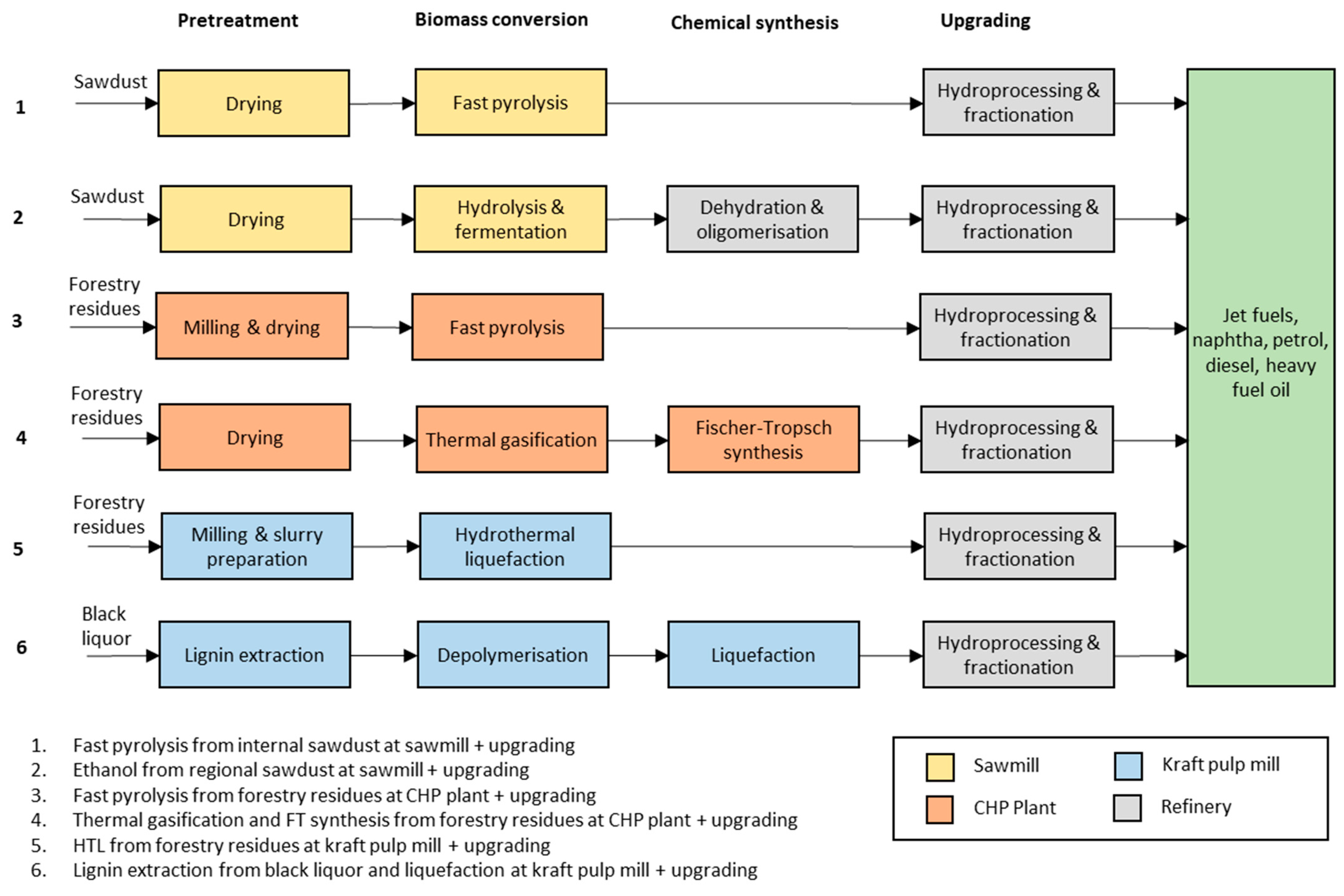
2.1. The Integrated Production Pathways Studied

Six production pathways that include the integrated production of different biofuel intermediates in existing bio-based plants, followed by upgrading at an existing refinery, were considered in this study, as outlined in Figure 1. These production pathways represent technically feasible options but do not cover all possible conversion technologies or combinations of technology and host industry. The bio-based host industries considered were sawmills, kraft pulp mills, and biomass-based CHP plants in the district heating system. These kinds of plants offer synergies in biomass logistics and know-how; furthermore, the by-products of sawmills and kraft pulp mills can be used as feedstock. Mechanical pulp mills also offer synergies in biomass logistics but were not included since they produce relatively low amounts of by-products that could be used as feedstock. Each of these three types of host industries was matched with two biomass conversion technologies. In total, five conversion technologies were selected: fast pyrolysis (included in two pathways), ethanol production via enzymatic hydrolysis and fermentation, gasification and FT synthesis, HTL, and kraft lignin extraction and liquefaction. These technologies represent a range of key technologies for producing biojet fuel from forest-based biomass and reflect ongoing entrepreneurial activities within the forest industry and oil companies in Sweden [28,29]. It was assumed that upgrading to fuel quality would take place at an existing refinery (although not necessarily via co-processing). This offers synergies in the hydrogen supply, fuel blending and distribution, as well as in various process units. Ethanol conversion to bio-oil in the AtJ pathway was also assumed to take place at a refinery and is thus regarded as part of the upgrading process.

2.2. Biomass Conversion Technologies

The characteristics of the biomass conversion technologies and biofuel intermediates, as well as the key upgrading requirements for producing biojet fuel, are summarised in Table 1.

2.2.1. Fast Pyrolysis

Fast pyrolysis involves the thermal decomposition of biomass in the absence of oxygen into pyrolysis vapours, also yielding the energy-rich by-products char and non-condensable gases. For maximal oil yield (up to about 65% on an energy basis), dried biomass should be rapidly heated to about 500 °C, followed by rapid cooling of the pyrolysis vapours into pyrolysis oil [31]. Fast pyrolysis oil typically contains about 35–40 wt% (dry oil) oxygen and 25 wt% water, and is prone to ageing [32]. To enable storage and transportation of the bio-oil, the addition of solvents such as methanol may be necessary, as well as certain physical upgrading, including, e.g., filtration to remove char and particulates [32]. Fast pyrolysis is a mature technology for the production of bio-oil that is used in stationary engines and boilers, while the upgrading to transportation fuel is under development [20,33].

2.2.2. Hydrothermal Liquefaction

HTL involves the thermal decomposition of biomass particles in a water slurry into a biocrude. The biocrude contains a complex mixture of organic compounds and has an oxygen content of 5–15 wt% [34]. HTL is an emerging process that is operated under high pressure (70–350 bar) and moderate temperatures (250–450 °C) in the presence of added alkali components that serve as a buffer and catalyst [35]. Apart from biocrude, the process generates energy-rich by-products including off-gas, solids (biochar and ashes), and an aqueous phase consisting of water-soluble organics. Most of the aqueous phase and a small fraction of the biocrude should be recycled in order to increase the biocrude yield, which can be as high as 85% on energy basis [36]. The removal of particulates may be necessary to enable storage and transportation.

2.2.3. Kraft Lignin Extraction and Liquefaction

Kraft pulping generates a residue stream called black liquor, which is rich in lignin. A proportion of the lignin can be extracted for use as feedstock in biofuel or chemical production. This reduces the load on the recovery boiler, which is often a bottleneck in pulp production [37]. Lignin extraction is possible via acid precipitation with CO2 (LignoBoost process), membrane separation, or electrolysis. In a process under development by SunCarbon, lignin is extracted via membrane separation, followed by depolymerisation in the presence of steam and alkali catalysts, and is finally suspended in gas oil or tall oil pitch. The energy yield of liquefied lignin (referred to as lignin oil) for this process has been estimated to about 70% [38]. Other options for liquefying the extracted lignin include fast pyrolysis and HTL [39].

2.2.4. Gasification and FT Synthesis

Biomass gasification involves the thermal decomposition of biomass at high temperatures (800–1100 °C) in the presence of steam and/or oxygen. This yields a raw synthesis gas that consists mainly of carbon monoxide and hydrogen, but also, e.g., methane, CO2, and tars. To enable downstream chemical synthesis, the synthesis gas must be cleaned and conditioned, which typically includes the reforming of tars and methane, a water–gas shift to adjust the H2/CO ratio, and CO2 removal. The synthesis gas then undergoes a catalysed polymerisation reaction that yields a range of hydrocarbons. By operating the reactors at low temperatures (200–240 °C), the output is optimised towards long-chain paraffins that are suitable for diesel and jet fuel production [40]. The FT reaction is highly exothermic and generates high-temperature waste heat. The yield of FT crude from solid biomass (wood) is in the range of 35–50% on an energy basis, assuming the recirculation of tail gases (unreacted gases and light hydrocarbons) from the FT reactor [40]. There is considerable experience of FT synthesis via gasification of fossil fuels, while experience related to biomass is limited to the demonstration scale [41].

2.2.5. Enzymatic Hydrolysis and Fermentation

The most common biochemical route for the production of ethanol from cellulosic biomass is enzymatic hydrolysis and fermentation [42]. The biomass must first undergo acid-catalysed steam pretreatment to break it down into a solid fraction consisting of cellulose and lignin, and a liquid fraction of hemicellulosic sugars. The cellulose is then enzymatically hydrolysed into monomeric sugars that are fermented into ethanol using yeast. The ethanol is recovered through distillation, which leaves an energy-rich residue, specifically stillage. The stillage contains a solid fraction of lignin that can be used as fuel, while the liquid fraction can be anaerobically digested to produce biogas. The ethanol yield is influenced by the feedstock but is typically about 35% on an energy basis [43]. Ethanol production from sugar and starch-rich crops is a mature and widely used process, while production based on forestry biomass such as wood chips has been demonstrated, but so far has not been undertaken on the industrial scale [44].
Table 1. Characteristics of the biomass conversion technologies and biofuel intermediates, and the key upgrading requirements for producing biojet fuel [4,26,31,34,39,43,45].
Biomass Conversion TechnologyBiofuel Intermediate
TechnologyCharacteristicsIntermediateCharacteristicsUpgrading Requirements
Fast pyrolysisThermal decomposition in the absence of oxygen. Up to 65% oil yield plus char and non-condensable gases. Mature technology for stationary applications. Small-scale is possible.Fast pyrolysis oilComplex mixture of organic compounds, including high amounts of aromatics and high acid content, and relatively unstable. Includes ~40 wt% (dry) oxygen and 25–35 wt% water.Oxygen removal, thermal/catalytic cracking of large molecules, and potential hydrocracking of aromatics and fractionation
Hydrothermal liquefactionThermal decomposition in a water slurry with alkali under high pressure. Up to 85% crude yield and possibly biogas from wastewater. Pilot/demonstration stage. HTL crudeComplex mixture of organic compounds, including high amounts of aromatics. Includes 5–15 wt% (dry) oxygen and 5–10% water.Oxygen removal, cracking of larger molecules, hydrocracking of aromatics, and fractionation.
Kraft lignin extraction and liquefactionExtraction of lignin from black liquor via membrane separation, depolymerisation using steam and alkali, and suspension in oil. Up 70% oil yield. Naturally integrated at kraft pulp mill. Lab-pilot stage.Lignin oilHigh amounts of aromatic hydrocarbons and phenols. Includes ~30 wt% oxygen.Oxygen removal, cracking of larger molecules and hydrocracking of aromatics, and fractionation.
Gasification and FT synthesisThermal decomposition in steam/oxygen at high temperatures to synthesis gas, gas cleaning, and polymerisation (FT synthesis). Yields 35–50% crude plus excess heat. Large-scale. Demonstration/commercial stage. FT crudeLong straight-chained hydrocarbons in the diesel/kerosene range (low-temp; FT process); very little oxygen and aromatics.Hydrocracking of heavier hydrocarbons, including waxes, and fractionation. May require isomerisation (transformation of straight-chained hydrocarbons to branched).
Enzymatic hydrolysis and fermentationAcid-catalysed steam pre-treatment, enzymatic hydrolysis of cellulose, and fermentation using yeast. Yields ~35% ethanol plus lignin and possibly biogas from wastewater. Fairly large-scale. Demonstration stage.Ethanol Ethanol: 47 wt% oxygen(Bio-oil: olefins (unsaturated hydrocarbons) of C9–C16). Dehydration, oligomerisation (polymerisation), hydrogenation, and fractionation

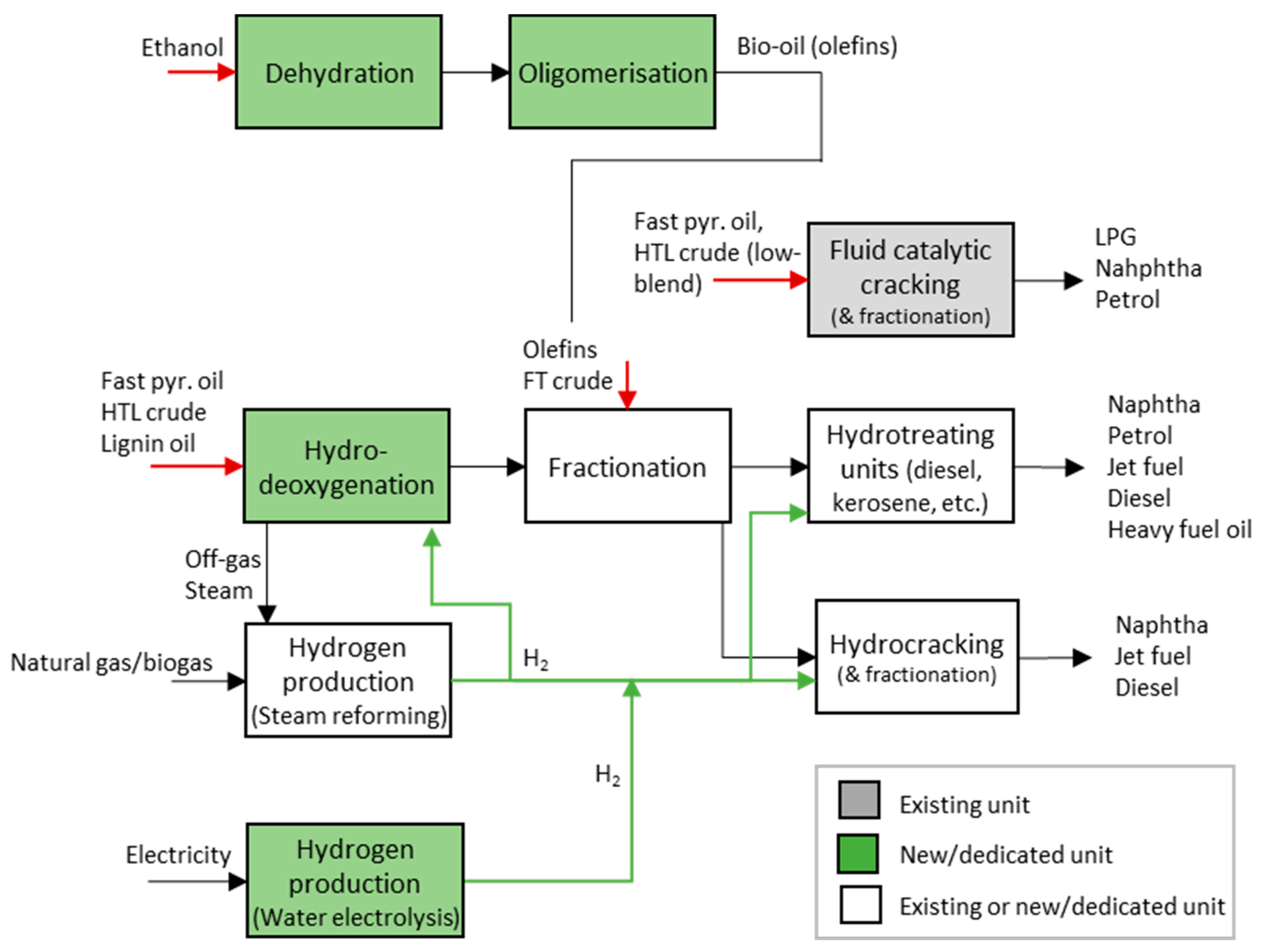
2.3. Upgrading of Biofuel Intermediates

The required upgrading to drop-in fuel quality differs between the biofuel intermediates depending on their characteristics (Table 1) but typically includes: (i) oxygen removal, (ii) cracking of large molecules, and (iii) fractionation into different products. There is industrial experience regarding upgrading FT crude (from fossil fuels) to fuel quality, while the upgrading of fast pyrolysis oil and HTL crude is limited to the laboratory and pilot scale [34], and is probably the least developed for lignin oil.
Oxygen removal is the main challenge in upgrading oxygen-rich bio-oils and can take place via different chemical processes. Hydrodeoxygenation (HDO) using hydrotreaters is generally the preferred process since it involves the lowest carbon yield losses. HDO involves exposing the bio-oil to hydrogen at elevated temperatures and pressures in the presence of a metal catalyst [46]. The process is highly exothermic and yields deoxygenated oil, wastewater, and off-gas that contains light hydrocarbons, CO, and CO2. Excess hydrogen from HDO is typically recycled. For lipid feedstocks (~10% oxygen content) used in the production of HVO and HEFA-SPK, it is possible to use modified hydrotreaters, which were originally designed for desulphurisation [33]. However, more oxygen-rich bio-oils require the design of dedicated hydrotreaters, which are not yet available on the industrial scale [47]. It has been proposed that HDO of oxygen-rich bio-oils be carried out in two steps: first under mild conditions and then under severe conditions at a hydrogen pressure of up to 140 bar [46].
The hydrogen requirement for HDO could partly be met by steam reforming of the off-gas from HDO. Other options for meeting the hydrogen requirement are steam reforming of natural gas or biogas and water electrolysis. Steam reforming is a two-step process in which the feedstock is catalytically reacted with steam to produce hydrogen and CO2 (by-product). Large-scale steam reformers have an average natural gas input of 1.3 MJ/MJ of hydrogen [48]. In water electrolysis, water is split into hydrogen and oxygen by applying electricity. Alkaline and polymer electrolyte membrane electrolysers are available at the industrial scale. They are operated at low temperatures (below 100 °C) and have efficiencies of 65–82% [48].
In the AtJ pathway, ethanol is “upgraded” via dehydration and oligomerisation, which are well-established processes in the petrochemical industry, followed by hydrogenation and fractionation [45]. Ethanol is dehydrated to ethylene by heating with sulphuric acid and then polymerised in a reactor that is operated at 250 bar and 200 °C. This yields a bio-oil consisting of olefins, primarily in the range of C12–C16, assuming the recirculation of C4–C8 components [49].
Cracking of large molecules (with or without hydrogen) can be applied to increase the yield of petrol, jet fuel, and diesel. Furthermore, hydrocracking may be necessary in order to reduce the aromatic content, which is high in HTL biocrude (~60%) and pyrolysis oil (~40%) [34], and is likely to be even higher in lignin oil. The permissible aromatic content in fuel is considerably lower for diesel (<8 vol%), jet fuel (8–25 vol% after blending), and petrol (<35 vol%) [50].
Fractionation of the bio-oil via distillation yields a range of products consisting mainly of naphtha, petrol, kerosene (jet fuel), diesel, and heavy fuel oil. Jet fuel is characterised by a chain length (C7–C17) and boiling range between as well as overlapping those of petrol (C4–C12) and diesel (C12–C20) [11]. The extraction of kerosene is thus optional in designing the fractionation and is conducted at the expense of the yields of diesel and petrol.

2.4. Existing Plant Infrastructures

2.4.1. CHP Plants in District Heating Systems

Swedish district heating systems supply approximately 200 PJ of heat per year [9]. About 80 biomass-fired CHP plants supply these systems and, in 2018, used a total of about 71 PJ of wood fuels [51,52]. Biomass logistics and storage are already in place for these plants. Furthermore, the majority of these plants utilise FB boilers [24], which can be retrofitted and combined with a pyrolysis or gasification reactor for the operation of dual FB technology [25,53]. Due to seasonal variations in heat demand, the CHP plants are typically operated 4000–5000 h per year (with less full-load hours), while industrial waste heat and heat from waste incineration plants often meet the baseload in the district heating systems.

2.4.2. Sawmills

There are approximately 140 sawmills in Sweden, which produced 18.6 Mm3 of sawn wood in 2019 [54]. About half of the saw logs eventually become wood chips, bark, and sawdust, of which sawdust is an especially interesting feedstock for biofuel production. Sawdust is currently used as fuel directly or is refined into wood pellets, the production of which amounted to 27 PJ in 2019 [55]. High-quality wood chips are sold as raw material for pulp production, while those of low quality, as well as bark, are used as fuel internally or externally. Most of the sawmills are stand-alone facilities with their own heat-only boiler that provides heat for drying of the sawn wood. Some of the larger sawmills are co-located with a pulp and paper mill, and receive heat from a shared/external CHP plant.

2.4.3. Kraft Pulp Mills

There are 17 kraft pulp mills in Sweden that produced a total of 5.62 Mdt of pulp in 2018 [56]. Most of the kraft pulp mills are integrated with paper production plants but not all. Modern non-integrated kraft pulp mills are self-sufficient in energy and are sometimes net exporters of electricity and bark. The kraft pulp mills generate large amounts of by-products that can be used as feedstock in biofuel production. In kraft pulping, about half of the wood (primarily cellulose) is converted into pulp, while the lignin and hemicelluloses eventually are combined into the black liquor. Furthermore, kraft pulp mills have a recovery boiler for burning black liquor, a bark boiler and turbine for the production of process heat and electricity, and a wastewater treatment plant. A small number of pulp mills also have a biogas plant for anaerobic digestion of the fibrous sludge from wastewater treatment [57].

2.4.4. Crude Oil Refineries

There are three crude oil refineries in Sweden along the west coast, two of which are located in Gothenburg and one, just north, in Lysekil. They annually refine about 21 Mt of crude oil to various transportation fuels and chemical feedstocks. The Preem refinery in Gothenburg also processes about 200,000 m3 of lipid feedstock for HVO in a separate hydrotreating unit [58]. The St1 refinery in Gothenburg is planning to start processing lipid feedstock for the production of 200,000 ton HVO and/or HEFA-SPK in 2022 [28]. None of the refineries process bio-oils from forest biomass apart from tall oil (lipid feedstock), a relatively low-volume by-product of chemical pulping.
The crude oil refineries differ in their configurations but typically host infrastructures for hydrogen, fuel blending and distribution, and wastewater treatment, and have process units for fractionation (of crude oil as well as downstream) and hydrotreating (for the removal of sulphur and other impurities). The refinery in Lysekil also hosts a fluid catalytic cracker (FCC) that increases the yield of petrol and chemical feedstocks, and a hydrocracker that increases the yield of diesel [58]. Jet fuel is currently produced in the two refineries in Gothenburg. Production is based on the kerosene stream directly from the crude oil distillation tower, which is the main route for jet fuel. It is, however, also possible to extract kerosene from the hydrocracker for jet fuel production.
The hydrogen requirement for hydrotreating various product streams is mainly met by the hydrogen that is formed in the catalytic reformation of the petrol stream. Additional hydrogen for hydrocracking (Preem refinery: Lysekil, Sweden) or hydrotreating of vegetable oils (Preem refinery: Gothenburg, Sweden) is produced by steam reforming of natural gas. At the steam reformer in Lysekil, Preem is currently operating a test facility for carbon capture and aims to develop this to full-scale carbon capture and storage (CCS) for the capture of 500,000 tCO2/y before 2025 [29].

2.5. Forestry Residues and By-Products

Table 2 presents data on the potential supply of forestry residues and the annual generation of forest industry by-products in Sweden. The extraction of forestry residues amounted to 32 PJ in 2019 [59], which indicates an untapped potential in mainly inland or northern regions. Forest industry by-products are currently used as fuel either internally in the forest industry, in the district heating sector, or for pellet production. The table also includes waste wood, which is used as fuel but is less suited as feedstock. Bark is also used as fuel but its relatively high ash content makes it less attractive as a feedstock, especially in ethanol production [43].

3. Methodological Approach

The approach used to estimate the technical potentials and system effects for each production pathway (as outlined in Figure 1) consisted of a number of steps, in which the value chain was divided into the production of biofuel intermediates and upgrading, which were addressed separately. The estimates of the production potentials were restricted by the potential for the integrated production of biofuel intermediates. The potential for upgrading at existing refineries was assumed to be unlimited since it does not necessarily involve co-processing.
The first step was to design a representative case for each production pathway for the integrated production of biofuel intermediates. The cases were designed based on data from the literature (sometimes with the author’s own adaptations) and are presented in Section 4.1, Section 4.2, Section 4.3, Section 4.4, Section 4.5 and Section 4.6. The production of sawn wood, district heat, and kraft pulp at the host industry was assumed to remain constant in the cases, while the net input of biomass and electricity changed. Regarding upgrading, data on the hydrogen requirement and the distribution of refined products were collected from the literature for each biofuel intermediate.
The second step was to identify eligible host industries for the integrated production of biofuel intermediates. This was conducted by mapping sawmills, kraft pulp mills, and CHP plants in district heating systems, and by applying criteria pertaining to each production pathway (Table 3). The criteria define the minimum size of the eligible host industries for each pathway, leading to the exclusion of some small host industries. The criteria were formulated based on qualified judgement and with consideration to the economy of scale of the conversion technologies. The plant size was defined by the production volumes of kraft pulp and sawn wood at kraft pulp mills and sawmills, respectively, and by the biomass input for the CHP plants, using data for 2018/19. Other site-specific characteristics were not taken into account.
The third step was to first estimate the potential production of biofuel intermediates for each pathway. This was done by scaling up the data from each case (which concerns integrated production at a host industry of a certain size) to the total size of the identified eligible host industries (Table S1 in Supplementary Materials). The production potentials for the biofuel intermediates were then combined with data on upgrading in order to estimate the potential production of biojet fuel and other refinery products, and the hydrogen requirement for each pathway. The total production potential and system effects in Sweden were then estimated for two combinations of complementary pathways, i.e., pathways that do not overlap in their use of plant facilities or on-site by-products (sawdust and black liquor). Combination A included production pathways 1, 3, 5, and 6, while Combination B included production pathways 2, 4, 5, and 6. Combination A is characterised by production pathways that involve fast pyrolysis (1 and 3), which is feasible on a relatively small scale but generates a bio-oil with high upgrading requirements. Combination B is characterised by production pathways that involve the production of cellulosic ethanol and FT crude (2 and 4). These technologies require relatively large plants, due to the economies of scale, and produce biofuel intermediates that require little hydrogen for upgrading. Both combinations include the two production pathways that involve integration at a kraft pulp mill (5 and 6).

4. Integrated Production Pathways: Cases and Upgrading Routes

Section 4.1, Section 4.2, Section 4.3, Section 4.4, Section 4.5 and Section 4.6 present the six cases that represent the first part of the production pathways, i.e., the production of biofuel intermediates at different bio-based plants. Section 4.7 presents possible upgrading routes for the different biofuel intermediates, the hydrogen required for upgrading, and the distribution of refined products.

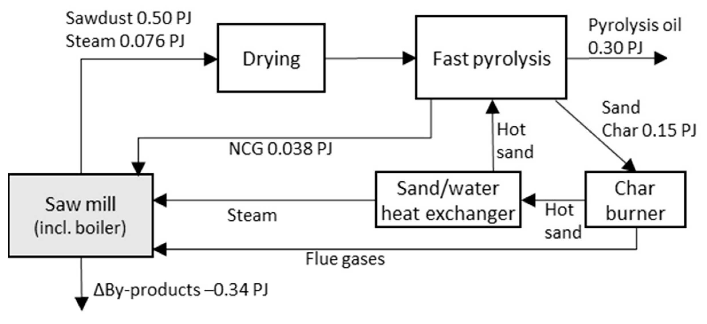
4.1. Sawmill: Fast Pyrolysis Oil from Sawdust

This case represents the integrated production of fast pyrolysis oil from on-site sawdust at a sawmill. The energy flows (Figure 2) have been adapted from Benjaminsson et al. [20]. The pyrolysis plant incorporates a separate char burner and heat exchanger, a concept that is applied at fairly small modular systems. Non-condensable gases from the pyrolysis reactor and hot flue gases from the char burner are sent to the steam production unit at the sawmill, which provides steam for drying the sawn wood and sawdust. A pyrolysis plant of this design is currently being built by Pyrocell, which is jointly owned by Setra and Preem at Setra’s sawmill in Gävle, Sweden, and is planned to start operation in late 2021 [62]. This case illustrates that a sawmill (producing 250,000 m3 sawn wood per year) could integrate the production of 0.30 PJ/y of pyrolysis oil from on-site sawdust. This would lead to a reduction in the net biomass exports of 0.34 PJ/y.

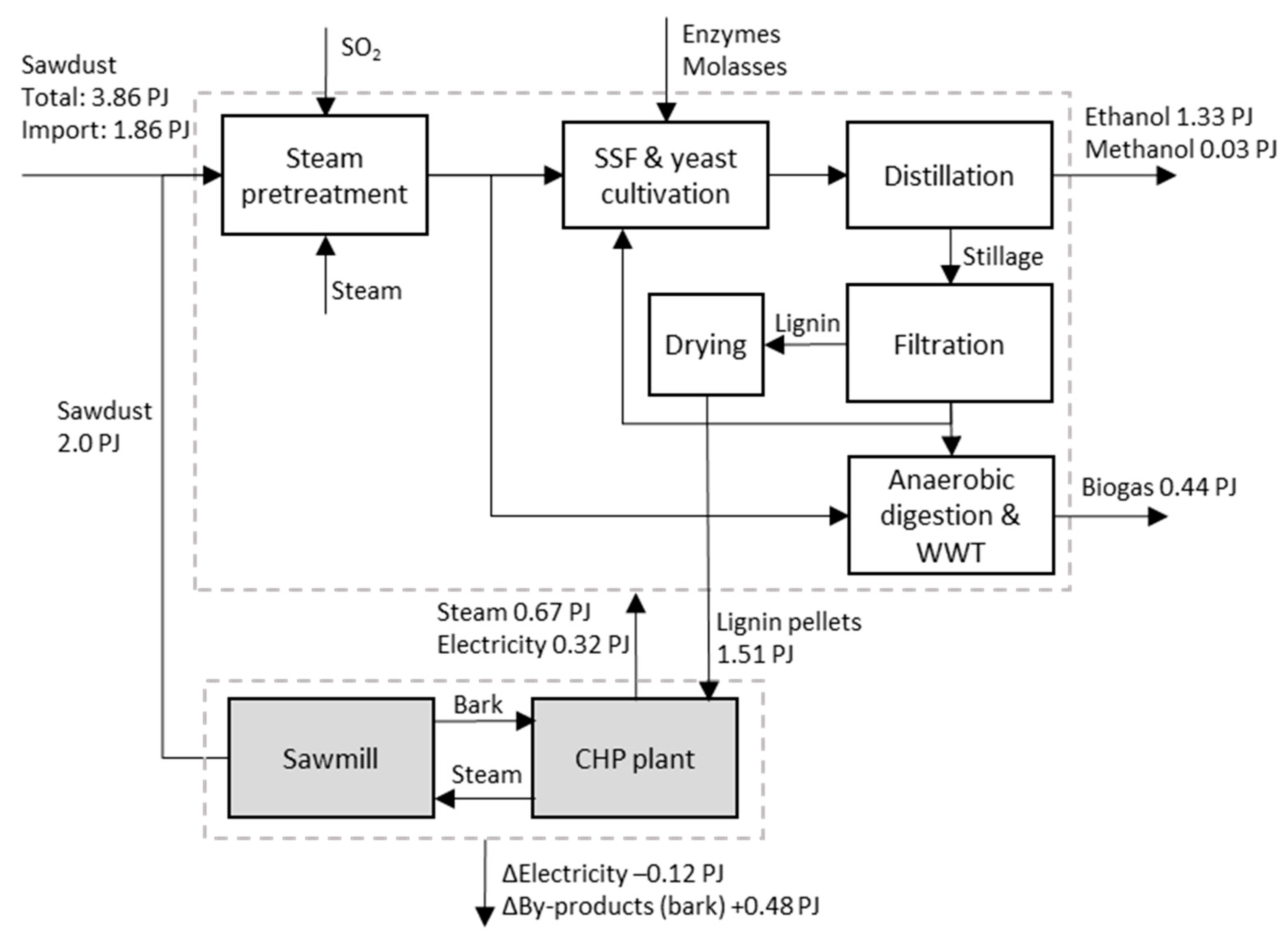
4.2. Sawmill: Ethanol from Sawdust

This case represents the integrated production of ethanol (and biogas) from sawdust at a sawmill. The energy flows (Figure 3) have been adapted from Haus et al. [63]. The ethanol plant is scaled to an annual sawdust input of 200,000 ton ds and is integrated with a large sawmill (producing 500,000 m3 sawn wood per year) that also imports sawdust from other sawmills in the region. The sawmill has access to a CHP plant that supplies steam to the sawmill and to the ethanol plant. The sawdust is first pretreated with acid-catalysed steam explosion, after which the solid fraction is fed to the simultaneous saccharification and fermentation reactor to produce ethanol. Yeast for the fermentation process is cultivated on site utilising molasses and liquid from the pretreated slurry. Ethanol and a small volume of methanol are recovered via distillation. The remaining stillage contains lignin that is filtered out, dried, and used as fuel in the CHP plant. The lignin (low-quality) could alternatively be used as feedstock for biofuel production via thermal gasification. The thin stillage and the liquid phase from steam pretreatment (containing hemicelluloses) are anaerobically digested for the production of biogas. This case illustrates the integrated production of 1.33 PJ/y of ethanol and 0.44 PJ/y of biogas at a large sawmill. This would entail an increase in the net biomass input of 1.38 PJ/y and a reduction in the net electricity output of 0.12 PJ/y.

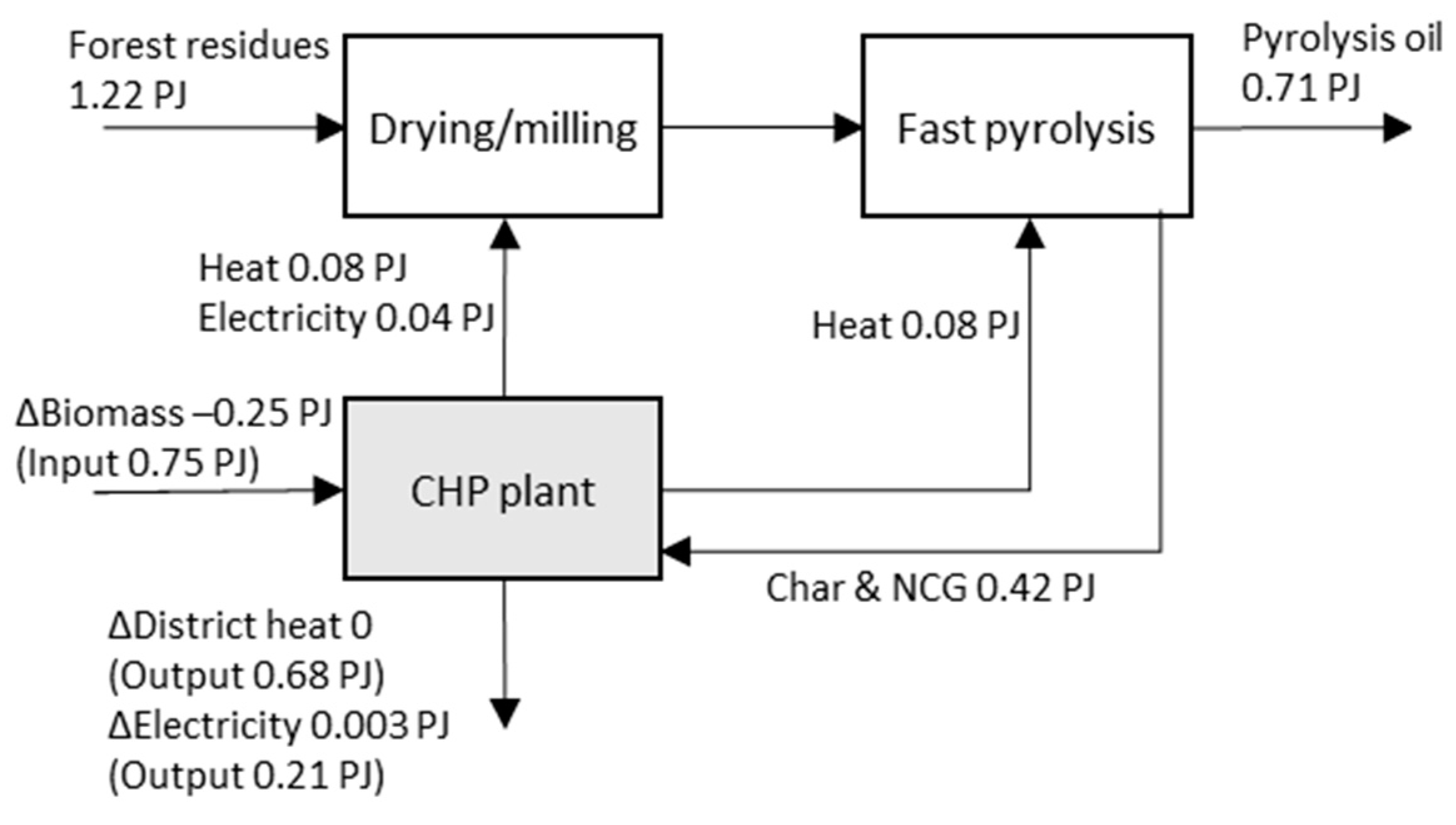
4.3. CHP Plant in District Heating Systems: Fast Pyrolysis Oil from Forestry Residues

This case represents the integrated production of fast pyrolysis oil from forestry residues via dual FB technology at a biomass-fired CHP plant. The retrofitted boiler receives both char and non-condensable gases from the pyrolysis reactor, and supplies heat to the reactor. The energy flows (Figure 4) have been adapted from Björnsson et al. [64] and assume operation during the heating season only (to maximise the overall energy efficiency), utilise flue-gas condensation, and maintain the production of district heat. This case shows that a CHP plant (with a previous biomass input of 1 PJ/y) could integrate the production of 0.71 PJ/y of pyrolysis oil. This would entail an increase in the net biomass input of 0.97 PJ/y.

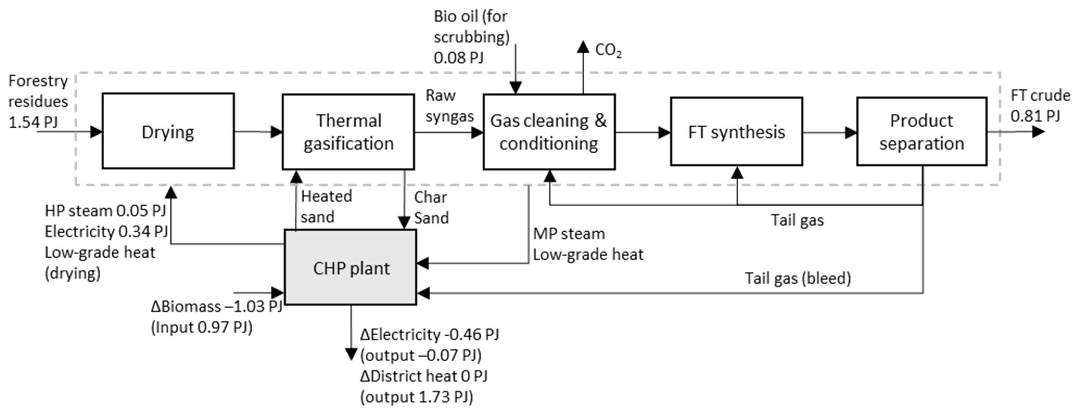
4.4. CHP Plant in District Heating System: FT Crude from Forest Residues

This case represents the integrated production of FT crude from forestry residues via dual FB technology at a biomass-fired CHP plant (with production of district heat). The retrofitted FB boiler supplies steam and heated sand to the FB gasifier. This type of indirect gasification in an FB gasifier has been demonstrated at the GoBiGas demonstration plant in Gothenburg, Sweden, although that plant involved downstream synthesis of biomethane instead of FT crude [53]. Tail gases from the FT reactors are recirculated to an electrically heated reformer (gas conditioning) in order to maximise the FT crude yield. The reformer consumes considerable amounts of electricity and could alternatively be heated by some of the tail gases but this would reduce the FT crude yield. The energy flows (Figure 5) have been adapted from Larsson et al. [22]. Additionally, it is assumed that the CHP plant utilises flue gas condensation and is operated at a 50%/50% mix of high and low load during the heating season only, and with a full energy recovery of process heat, tail gases, and char. The energy flows show that a considerable proportion of the district heat is produced from energy recovered from the FT process.
This case shows that a CHP plant (with a previous biomass input of 2 PJ/y) could integrate the production of 0.81 PJ/y of FT crude and that this would entail an increase in the net biomass input (including bio-oil for scrubbing) of 0.58 PJ/y. Moreover, the retrofitted CHP plant would become a net importer of electricity due not only to the high electricity consumption but also due to the reduction in electricity production resulting from high-pressure steam being diverted to gasification and gas conditioning.

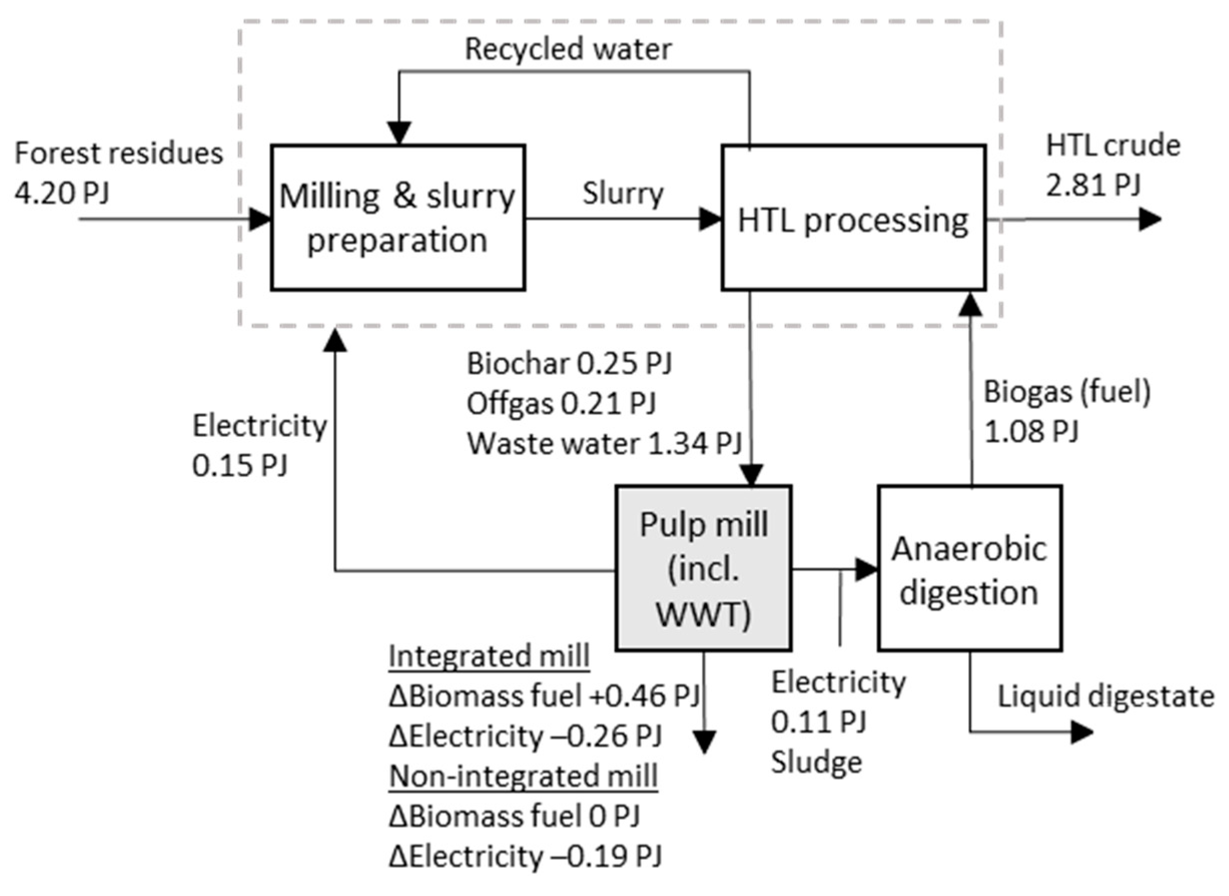
4.5. Kraft Pulp Mill: HTL Crude from Forest Residues

This case represents the integrated production of HTL crude from forestry residues at a kraft pulp mill. The energy flows (Figure 6) have been adapted from Nie and Bi [65] and Tews et al. [46]. The forestry residues are milled and mixed with hot water recycled from the HTL reactor to form a biomass–water slurry. The slurry also contains added alkalis that serve as buffer and catalyst. The slurry is pressurised and sent to the HTL reactor in which biocrude, off-gas, biochar, and wastewater are produced. The off-gas and char are burnt in the recovery boiler, while the wastewater (bled from the recycled water) is treated in the pulp mill’s wastewater treatment plant. The sludge from the wastewater treatment plant is anaerobically digested for the production of biogas, which is used as fuel in the HTL process. The digester is heated with waste heat from the pulp mill. The HTL process was scaled to ensure that the off-gas and biochar corresponded to 5% of the energy input to the recovery boiler.
This case illustrates that a kraft pulp mill (producing 400 kdt/y) could integrate the production of 2.81 PJ/y of HTL crude. This would entail an increase in the net biomass input of 3.74 PJ/y for an integrated pulp and paper mill. For a non-integrated pulp mill, an alternative configuration, in which the HTL process is heated by steam from the pulp mill, appears more attractive. This would enable the upgrade of the biogas for external use.

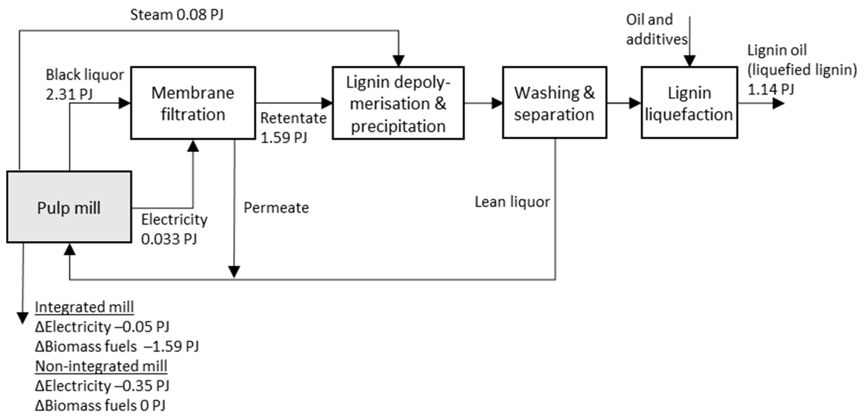
4.6. Kraft Pulp Mill: Lignin Oil

This case represents the integrated production of kraft lignin oil at a kraft pulp mill. The energy flows (Figure 7) have been adapted from Jafri et al. [26]. A fraction of the weak (non-evaporated) black liquor (25%) is extracted for membrane filtration. The lignin-rich retentate stream is mixed with steam and fed to a depolymerisation reactor, in which the alkali components in the retentate stream serve as catalysts. The depolymerised lignin is then precipitated with low-purity CO2, washed, and liquefied by suspension in fuel oil or tall oil pitch. The alkali-rich permeate and lean liquor from washing are recycled back to the evaporation unit of the pulp mill.
This case shows that a kraft pulp mill (producing 400 kdt/y) could integrate the production of 1.14 PJ/y lignin oil, assuming the extraction of a maximum of 25% of the black liquor. This would entail either an increase in the net biomass input of up to 1.59 PJ/y (integrated pulp and paper mill) or a reduction in the net electricity production of 0.35 PJ/y (non-integrated pulp mill).

4.7. Refinery: Upgrading of Biofuel Intermediates

Biofuel intermediates can be upgraded at an existing refinery through co-processing in existing refinery units directly or after HDO, or by processing in a dedicated co-located facility that benefits from existing infrastructures. It should be noted that to date, the certification of jet fuels only allows small volumes (~5 vol%) of lipid feedstock or FT crude to be co-processed with fossil feedstock [11]. Figure 8 illustrates possible upgrading routes for different biofuel intermediates at a crude oil refinery. It is highly uncertain how oxygen-rich bio-oils will be handled in the future but there seems to be a consensus that some degree of HDO of the bio-oil is preferable before insertion into existing processes [4]. Hydrotreaters and hydrocrackers are especially sensitive to oxygen, while the FCC is more tolerant [4]. Complete oxygen removal is, however, probably not required and could be unnecessarily costly since the last remaining oxygenated compounds are usually more difficult to break [66]. After HDO, the deoxygenated oil can be fractionated into different product streams that are sent to their respective final hydrotreating units or hydrocrackers (heavy fractions). These units can be dedicated to bio-oils or shared with petroleum streams. FT crude and bio-oil from ethanol do not require HDO. The “upgrading” of ethanol, however, requires dedicated units for dehydration and oligomerisation.
The HDO of oxygen-rich bio-oils requires a large amount of hydrogen that is largely proportional to the oxygen content (Table 4). The hydrogen consumption in hydrocracking could potentially also be substantial for certain bio-oils depending on their chemical composition (the content of aromatics and long molecules) and on the desired product mix. HDO and hydrocracking require the use of hydrogen at elevated pressures (possibly up to 140 bar in the second step of HDO) [46]. Some of this hydrogen could be produced via steam reforming of the off-gas from the HDO. The material and energy flows in Tews et al. [46] suggest that up to 80% of the hydrogen required for HDO of fast pyrolysis oil could be produced from the off-gas from HDO. In that study, all the required hydrogen was produced from the off-gas (from hydro-processing) and the non-condensable gases (from the pyrolysis reactor), where the off-gas accounted for 80% of the mass flow of hydrocarbons. It is, however, not certain that this can be achieved in practice. The remaining hydrogen requirement must be obtained from external sources such as natural gas or biogas (via steam reforming), or electricity (via water electrolysis).
The distribution of refined products depends on the composition of the biofuel intermediates and on the configuration of the upgrading process. The distributions presented in Table 4 reflect configurations that benefit jet fuel over petrol and diesel. The biojet fraction in the fuel mix is highest for the upgrading of ethanol at about 70% [45], up to 50% for FT crude, and 20–30% for both HTL crude and fast pyrolysis oil (this could possibly be increased by hydrocracking of the heavy fuel oil) [34]. For comparison, the jet fuel fraction at existing crude oil refineries is typically around 10% [4].
An alternative process to HDO is the co-processing of untreated or partly deoxygenated bio-oil/crude in an existing FCC together with vacuum gas oil, which is the heaviest petroleum fraction from the crude distillation tower [4]. The main products of the FCC are liquefied petroleum gas, naphtha, and petrol [4]. No hydrogen is added to the FCC; instead the oxygen in the bio-oil is removed via hydrogen transfer from compounds in the vacuum gas oil and via forming CO2 and CO. Studies have shown that it is possible to co-process up to 10 wt% of untreated fast pyrolysis oil in an FCC after minor modifications of the feeding system [67].

5. Results and Discussion: Technical Potentials and System Effects

This section presents and discusses the estimated technical potential and system effects for the six production pathways. The results for each pathway are presented in Table 5. The results for the two alternative combinations of complementary pathways (denoted Combination A and B) are presented in Figure 9. Combination A is the combined results of the complementary pathways 1, 3, 5 and 6 and Combination B of 2, 4, 5 and 6.

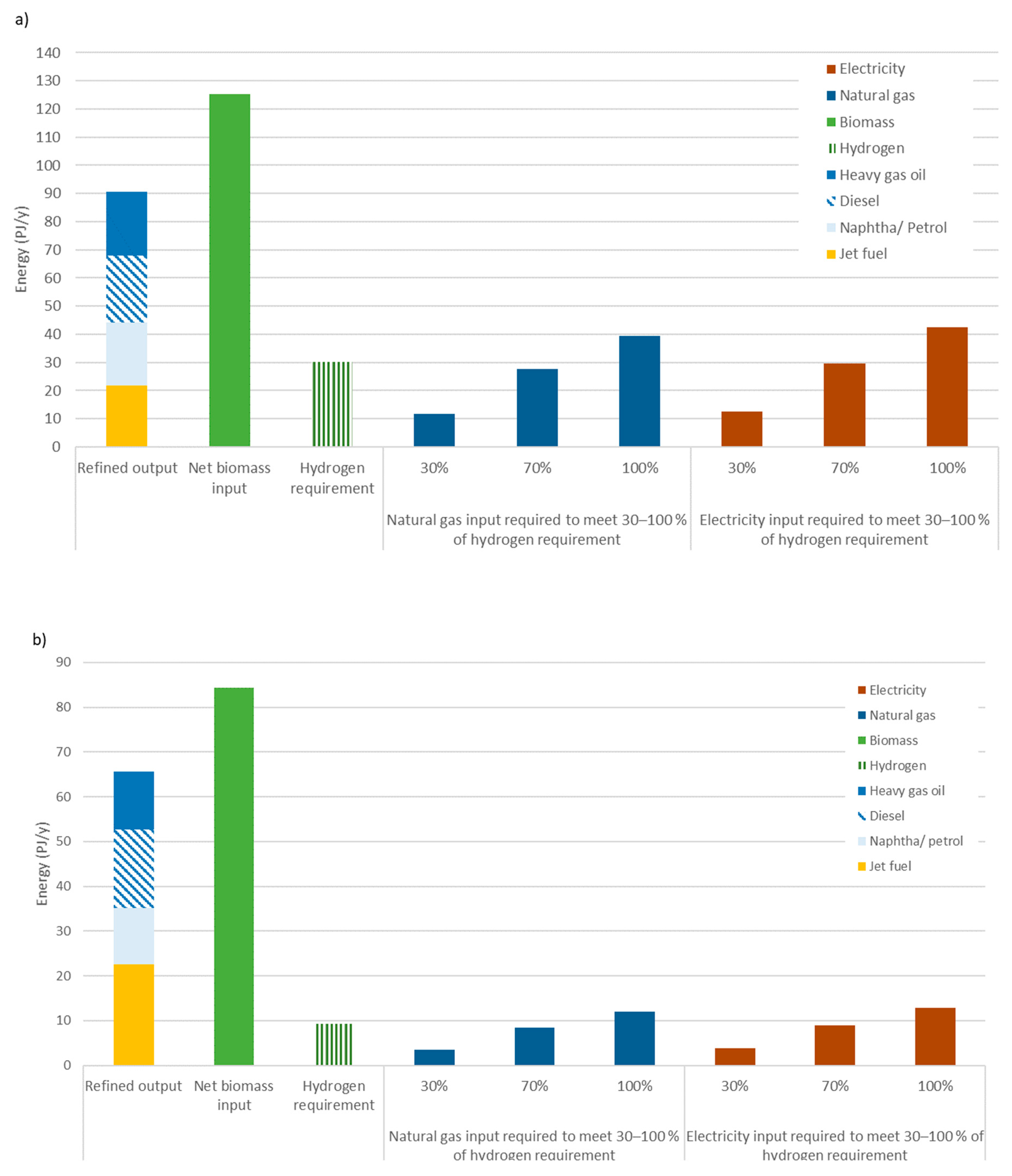
5.1. Integrated Production of Biofuel Intermediates and Net Biomass Input

The results of this study show that biomass-fired CHP plants and kraft pulp mills have the greatest potential for the integrated production of biofuel intermediates. The CHP plants could integrate the production of 42 PJ/y of pyrolysis oil (retrofitting of CHP plants >1 PJ/y of biomass input) or alternatively up to 15 PJ/y of FT crude (CHP plants >2 PJ/y of biomass; this could be combined with the co-production of pyrolysis oil in CHP plants with biomass input <2 PJ/y). The kraft pulp mills could integrate the production of 33 PJ/y of HTL and 13 PJ/y of lignin oil. The sawmills could integrate the production of up to 13 PJ/y of fast pyrolysis oil from on-site sawdust or alternatively up to 8 PJ/y of ethanol and 2.6 PJ/y of biogas, assuming a regional supply of sawdust provided to large sawmills.
The estimated potentials should be regarded as upper-end values of the production potential of each pathway since no site-specific factors, apart from plant size, were considered when identifying eligible host industries. Important site-specific factors to consider include, for example, the availability of forestry residues in the region or access to a harbour (especially for CHP plants); the available capacity of the recovery boiler and wastewater treatment plant at kraft pulp mills; and recent investments in wood pellet production at sawmills.
The net biomass inputs for Combinations A and B were estimated to be 125 and 84 PJ/y, respectively (Figure 9). This amount of biomass, i.e., up to 125 PJ/y, could be met by Swedish forestry residues and by-products (see Section 2.5) but would require that some of their current use as fuel be gradually reduced. This could be achieved by continuous efforts towards improved energy efficiency in the forest industry, in combination with the electrification of certain processes [68].
The technical potentials were calculated based on current conditions in the bio-based plants, although the production pathways studied have not yet been adopted on a large scale and thus can only reach wide implementation in 10–20 years. Until then, the plant infrastructure is likely to change. Two possible developments include a continued consolidation of the forest industry into larger units and a moderate decrease in the demand for district heat due to more energy efficient buildings and warmer climate [69]. Larger units in the forest industry could potentially facilitate the integration of biofuel production, especially at sawmills, while the development in the district heating sector could reduce the opportunity for integrated biofuel production at CHP plants.

5.2. Refined Output in Relation to GHG Mandates and Goals

The total annual output of refined bio-based products was estimated to be 90 PJ for Combination A and 65 PJ for Combination B (Figure 9). This includes: 22 PJ (A) and 23 PJ (B) of biojet fuel; 24 PJ (A) and 18 PJ (B) of biodiesel; 22 PJ (A) and 13 PJ (B) of bio-based naphtha/petrol; and 23 PJ (A) and 13 PJ (B) of bio-based marine fuel (heavy fuel oil). The output of bio-based jet fuel, diesel, petrol and naphtha could probably be increased somewhat at the expense of heavy fuel oil and total yield. The results indicate that it could be possible to produce the volumes that are expected to be required to meet the Swedish GHG mandates for 2030 for jet fuel (~15 PJ) and petrol (~18–21 PJ), but not for diesel (~115–170 PJ; see Table 6). The volumes expected to be required for meeting the mandates are based on underlying scenarios of future use of jet fuel, diesel, and petrol, and on assumptions concerning the GHG emissions of the bio-based fuels. The intervals for diesel and petrol reflects different assumptions concerning, e.g., the rate of electrification of the vehicle fleet. The pathways studied in this paper have the potential to provide biojet fuel with low GHG emissions due to the use of residues and by-products as feedstock, and assuming the use of low-carbon hydrogen for upgrading. In the short-term, HVO and HEFA-SPK will be necessary to meet the GHG mandates for diesel and jet fuel since the production pathways studied have not yet been adopted at scale.
There are currently no binding GHG mandates or similar climate policy instruments that target marine fuels or feedstock for chemicals and plastics. Nearly all the marine fuels bunkered in Sweden are used for international shipping, which is regulated by the International Maritime Organization (IMO). The IMO has adopted a target of reducing GHG emissions from international shipping by at least 50% by 2050 [70] but it is unclear how this will be enforced. Sweden and many other countries aim to have no net emissions of GHG by mid-century (2045 in Sweden). This will necessitate a radical reduction in the use of fossil fuels and feedstock over the coming decades, and will likely increase the demand for biojet fuel and other bio-based transportation fuels and chemical feedstock.
Table 6. The use of liquid transportation fuels and petroleum-based feedstock for chemicals and plastics in 2018 in Sweden and the GHG mandates for 2030 [9,71].
Type of Transportation Fuel/FeedstockUse in 2018 (PJ)GHG Mandate for 2030
Fossil ComponentBio-Based ComponentStipulated Emission Reduction for 2030 (%)Expected Required Volume of Bio-Based Component in 2030 (PJ/y)
Jet fuel47~02715 c
Diesel13253 a66~115–170 e
Petrol (including ethanol)854 b28~18–21 f
Marine fuels111 d~0--
Petroleum-based feedstock (excluding natural gas) for chemicals and plastics, e.g., naphtha and propane76 g~0--
a HVO and fatty acid methyl esters, most of which are blended with fossil diesel. b Ethanol, most of which is blended with petrol. c This is based on the assumption of a blend-in of 30 vol% of a biojet fuel that has 90% lower GHG emissions than fossil jet fuel [72]. d About 95% is used in international shipping and about 5% in the domestic maritime sector [9]. e The interval reflects different assumptions underlying the scenarios, e.g., the shift to electric vehicles [71]. f Roughly half of this amount is assumed to be ethanol (which is restricted to low-blend) and half to bio-petrol [71]. g [73].

5.3. Hydrogen Requirements and External Inputs

The annual hydrogen requirement was estimated to be 30 PJ for Combination A and 4 PJ for Combination B. It is unclear how much of this hydrogen can be produced from internal off-gases and thus the amount of external input required is unclear as well. For Combination A, the use of external inputs was estimated to be 13–42 PJ/y of electricity or 12–40 PJ/y of natural gas/biogas, assuming they account for 30–100% of the hydrogen requirement (Figure 9). For comparison, the Swedish production of biogas in 2018 amounted to 7.4 PJ and the use of natural gas to 41 PJ, 14 PJ of which was used as feedstock [9]. Swedish electricity production amounted to 160 TWh (580 PJ) in 2018.
The pathways that involve fast pyrolysis, HTL, and lignin oil production require substantial amounts of hydrogen for upgrading, while those that involve FT synthesis and ethanol production as well as conversion require little hydrogen (Table 5). However, large amounts of hydrogen could be used in the FT pathway if the biomass conversion to FT crude is boosted with hydrogen in order to improve the relatively low carbon efficiency [74,75]. It should also be noted that the pathways that require large amounts of hydrogen for upgrading may be advantageous in other respects, such as regarding high biomass conversion efficiency and greater ease of application on fairly small scales (fast pyrolysis).
Hydrogen production with low carbon intensity will be of key importance for achieving good climate performance of the production pathways that require large volumes of hydrogen. The climate performance influences the volumes required to meet the GHG mandate and thus the willingness to pay for the fuels. For pathways that require large volumes of hydrogen, natural gas is unlikely to be a viable option for hydrogen production unless it is combined with CCS, while electrolysis appears attractive in Sweden and other countries with low-carbon electricity supplies.
A potential short-term upgrading strategy would be to co-process the bio-oil/crude in the FCC, as this reduces the hydrogen requirement. However, this upgrading route is not ideal for the production of jet fuel or diesel. Furthermore, the carbon efficiency and thus the environmental performance of the process is unclear. The current FCC capacity in Sweden (the Preem refinery in Lysekil) is about 1.8 Mton of vacuum gas oil/year [76], which could allow for the co-processing of up to about 180,000 t bio-oil (10 wt%). This corresponds to about 2 PJ, assuming 17 MJ/kg dry pyrolysis oil and 30% water content.

6. Conclusions and Final Remarks

The potential production of biojet fuel in Sweden has been estimated using six integrated production pathways and both the net biomass input and hydrogen requirements for upgrading have been analysed. The results thus reflect the production pathways selected and the ways in which they were configured, as well as provide an indication of how much biojet fuel can be produced within existing plant infrastructures in Sweden.
The total potential production of bio-based transportation fuels was estimated to be 90 PJ/y when combining four complementary production pathways (Combination A). The related net biomass input was estimated to be 125 PJ/y. This amount of biomass can be obtained from Swedish forestry residues and by-products, assuming that some of their current use as fuel is gradually reduced. The potential for the production of biojet fuel and biodiesel was estimated to be 22 PJ/y and 24 PJ/y, respectively, for Combination A. The estimated production potential for biojet fuel is higher than that expected to be required to meet the Swedish GHG mandate for 2030, while that for biodiesel is considerably lower. It is unclear to what extent the GHG mandate for jet fuel will spur investments in Sweden in the production pathways studied here, as the mandates can also be met by importing HEFA-SPK or lipid feedstock, as has largely been the case for road transportation fuels. HEFA-SPK and HVO will be necessary to meet the GHG mandates for jet fuel and diesel in the short term. Competition for these fuels and lipid feedstock is, however, likely to increase as more countries adopt policies that force airlines to use SAF. This highlights the challenge in meeting future GHG mandates for both diesel and jet fuel.
The hydrogen requirement for upgrading differs markedly between the pathways, being highest for those that involve fast pyrolysis and lowest for those that involve FT synthesis as well as ethanol production and conversion. The hydrogen requirement for Combination A (involving fast pyrolysis) was estimated to be 30 PJ/y. The extent to which off-gas from HDO can contribute to the hydrogen supply is uncertain and this has a considerable impact on the demand for external resources such as electricity, biogas, and natural gas.
The results of this study show that there is considerable potential for the integrated production of biofuel intermediates in existing Swedish plants, especially CHP plants and kraft pulp mills. Sweden is rich in forestry residues and by-products but will nevertheless face biomass resource constraints in the climate transition that will require a gradual phase-out of fossil fuels across sectors. The biomass constraints are likely to be more evident in a European and global context. Complementary strategies to biojet fuels and biofuels should therefore also be pursued.

Supplementary Materials

The following are available online at https://www.mdpi.com/article/10.3390/en14206531/s1, Table S1: Summary of data for the cases and the estimated production potentials of biofuel intermediates and its system effects national level. The estimates were made scaling up the data for the cases to the total size of the identified eligible host industries. Table S2: Data behind Figure 9.

Funding

This research was funded by the Swedish Energy Agency, 48429-1, and the APC was jointly funded by the Swedish Energy Agency and Lund University.

Institutional Review Board Statement

Not applicable.

Informed Consent Statement

Not applicable.

Data Availability Statement

Not applicable.

Acknowledgments

This work was funded by the Swedish Energy Agency (project number 48429-1). The study has benefited from fruitful discussions with my colleagues in the project group: Lovisa Björnsson, Pål Börjesson, and Mikael Lantz. I am also grateful to my colleagues Bengt Johansson and Fredric Bauer for their valuable comments on an earlier draft of this paper.

Conflicts of Interest

The author declares no conflict of interest.

References

  1. IEA. Aviation; Tracking Report; IEA: Paris, France, 2020. [Google Scholar]
  2. Larsson, J.; Elofsson, A.; Sterner, T.; Åkerman, J. International and national climate policies for aviation: A review. Clim. Policy 2019, 19, 787–799. [Google Scholar] [CrossRef] [Green Version]
  3. Transport & Environment. Roadmap to Decarbonising European Aviation; Transport & Environment: Brussels, Belgium, 2018. [Google Scholar]
  4. van Dyk, S.; Su, J.; Mcmillan, J.D.; Saddler, J. Potential synergies of drop-in biofuel production with further co-processing at oil refineries. Biofuels Bioprod. Biorefining 2019, 13, 760–775. [Google Scholar] [CrossRef] [Green Version]
  5. IRENA. Biofuels for Aviation: Technology Brief; International Renewable Energy Agency: Abu Dhabi, United Arab Emirates, 2017. [Google Scholar]
  6. Ydesbond, I.M.; Kristensen, N.B.; Thune-Larsen, H. Nordic Sustainable Aviation; TemaNord 2020:536; Nordic Council of Ministers: Copenhagen, Denmark, 2020.
  7. European Commission. Proposal for a Regulation of the European Parliament and of the Council on Ensuring a Level Playing Field for Sustainable Air Transport; COM(2021) 561 Final; European Commission: Brussels, Belgium, 2021. [Google Scholar]
  8. SFS 2021:412. Lag om Reduktion av Växthusgasutsläpp från Vissa Fossila Drivmedel [Law on the Reduction of Greenhouse Gas Emissions from Certain Fossil Fuels]; Swedish Government: Stockholm, Sweden, 2021.
  9. SEA. Facts and Figures-Energy in Sweden 2020; Swedish Energy Agency: Eskilstuna, Sweden, 2020. [Google Scholar]
  10. Doliente, S.S.; Narayan, A.; Tapia, J.F.D.; Samsatli, N.J.; Zhao, Y.; Samsatli, S. Bio-aviation Fuel: A Comprehensive Review and Analysis of the Supply Chain Components. Front. Energy Res. 2020, 8, 110. [Google Scholar] [CrossRef]
  11. van Dyk, S.; Saddler, J. Progress in Commercialization of Biojet/Sustainable Aviation Fuels (SAF): Technologies, Potential and Challenges; IEA Bioenergy Task 39; IEA Bioenergy: Ottawa, ON, Canada, 2021. [Google Scholar]
  12. IRENA. Reaching Zero with Renewables: Biojet Fuels; International Renewable Energy Agency: Abu Dhabi, United Arab Emirates, 2021. [Google Scholar]
  13. Gutiérrez-Antonio, C.; Gómez-Castro, F.I.; de Lira-Flores, J.A.; Hernández, S. A review on the production processes of renewable jet fuel. Renew. Sustain. Energy Rev. 2017, 79, 709–729. [Google Scholar] [CrossRef]
  14. IATA Sustainable Aviation Fuel: Technical Certification (Facts Sheet). Available online: https://www.iata.org/contentassets/d13875e9ed784f75bac90f000760e998/saf-technical-certifications.pdf (accessed on 24 May 2021).
  15. de Jong, S.; Hoefnagels, R.; Faaij, A.; Slade, R.; Mawhood, R.; Junginger, M. The feasibility of short-term production strategies for renewable jet fuels—A comprehensive techno-economic comparison. Biofuels Bioprod. Biorefining 2015, 9, 778–800. [Google Scholar] [CrossRef]
  16. de Jong, S.; Antonissen, K.; Hoefnagels, R.; Lonza, L.; Wang, M.; Faaij, A.; Junginger, M. Life-cycle analysis of greenhouse gas emissions from renewable jet fuel production. Biotechnol. Biofuels 2017, 10, 64. [Google Scholar] [CrossRef] [PubMed] [Green Version]
  17. de Jong, S.; Hoefnagels, R.; Wetterlund, E.; Pettersson, K.; Faaij, A.; Junginger, M. Cost optimization of biofuel production—The impact of scale, integration, transport and supply chain configurations. Appl. Energy 2017, 195, 1055–1070. [Google Scholar] [CrossRef] [Green Version]
  18. Karvonen, J.; Kunttu, J.; Suominen, T.; Kangas, J.; Leskinen, P.; Judl, J. Integrating fast pyrolysis reactor with combined heat and power plant improves environmental and energy efficiency in bio-oil production. J. Clean. Prod. 2018, 183, 143–152. [Google Scholar] [CrossRef]
  19. Börjesson Hagberg, M.; Pettersson, K.; Ahlgren, E.O. Bioenergy futures in Sweden—Modeling integration scenarios for biofuel production. Energy 2016, 109, 1026–1039. [Google Scholar] [CrossRef] [Green Version]
  20. Benjaminsson, G.; Benjaminsson, J.; Bengtsson, N. Decentraliserad Produktion av Pyrolysolja för Transport till Storskaliga Kraftvärmeverk och Förgasningsanläggningar; Gasefuels AB: Gothenburg, Sweden, 2013. [Google Scholar]
  21. Gustavsson, C.; Nilsson, L. Co-production of Pyrolysis Oil in District Heating Plants: Systems Analysis of Dual Fluidized-Bed Pyrolysis with Sequential Vapor Condensation. Energy Fuels 2013, 27, 5313–5319. [Google Scholar] [CrossRef]
  22. Larsson, A.; Gustafsson, G.; Gustavsson, C. Cogeneration of Biojet in CHP Plants; Report 2020:664; Energiforsk: Stockholm, Sweden, 2020. [Google Scholar]
  23. Ekbom, T.; Hjerpe, C.; Hagström, M.; Herman, F. Pilot Study of Bio-jet A-1 Fuel Production for Stockholm-Arlanda Airport; Värmeforsk: Stockholm, Sweden, 2009. [Google Scholar]
  24. Gustavsson, C. Added Value from Biomass by Broader Utilization of Fuels and CHP Plants. Ph.D. Thesis, Karlstads Universitet, Karlstad, Sweden, 2016. [Google Scholar]
  25. Gustavsson, C.; Hulteberg, C. Co-production of gasification based biofuels in existing combined heat and power plants—Analysis of production capacity and integration potential. Energy 2016, 111, 830–840. [Google Scholar] [CrossRef]
  26. Jafri, Y.; Wetterlund, E.; Anheden, M.; Kulander, I.; Håkansson, Å.; Furusjö, E. Multi-aspect evaluation of integrated forest-based biofuel production pathways: Part 1. Product yields & energetic performance. Energy 2019, 166, 401–413. [Google Scholar] [CrossRef]
  27. Jafri, Y.; Wetterlund, E.; Anheden, M.; Kulander, I.; Håkansson, Å.; Furusjö, E. Multi-aspect evaluation of integrated forest-based biofuel production pathways: Part 2, economics, GHG emissions, technology maturity and production potentials. Energy 2019, 172, 1312–1328. [Google Scholar] [CrossRef]
  28. St1. Game Changer—St1 Nordic Oy Integrated Annual Report 2019; St1: Helsinki, Finland, 2020. [Google Scholar]
  29. Preem. Sustainability Report 2019; The Target Is Set: Climate Neutral by 2045; Preem: Stockholm, Sweden, 2020. [Google Scholar]
  30. de Jong, S. Green Horizons—On the Production Costs Climate Impacts and Future Supply of Renewable Jet Fuels. Ph.D. Thesis, Utrecht University, Utrecht, The Netherlands, 2018. [Google Scholar]
  31. Bridgwater, T. Challenges and Opportunities in Fast Pyrolysis of Biomass: Part I. Johns. Matthey Technol. Rev. 2018, 62, 118–130. [Google Scholar] [CrossRef]
  32. Gollakota, A.R.K.; Reddy, M.; Subramanyam, M.D.; Kishore, N. A review on the upgradation techniques of pyrolysis oil. Renew. Sustain. Energy Rev. 2016, 58, 1543–1568. [Google Scholar] [CrossRef]
  33. von Schenck, A.; Berglin, N. Pyros-Roadmap for Realisation of a Value Chain from Forest to Biofuels Via Bio-Oil; Report 2018:550; Energiforsk: Stockholm, Sweden, 2018. [Google Scholar]
  34. van Dyk, S.; Su, J.; Ebadian, M.; O’Connor, D.; Lakeman, M.; Saddler, J. Potential yields and emission reductions of biojet fuels produced via hydrotreatment of biocrudes produced through direct thermochemical liquefaction. Biotechnol. Biofuels 2019, 12, 281. [Google Scholar] [CrossRef] [PubMed] [Green Version]
  35. Perkins, G.; Batalha, N.; Kumar, A.; Bhaskar, T.; Konarova, M. Recent advances in liquefaction technologies for production of liquid hydrocarbon fuels from biomass and carbonaceous wastes. Renew. Sustain. Energy Rev. 2019, 115, 109400. [Google Scholar] [CrossRef]
  36. Jensen, C.U.; Guerrero, J.K.R.; Karatzos, S.; Olofsson, G.; Iversen, S.B. 10-Hydrofaction™ of forestry residues to drop-in renewable transportation fuels. In Direct Thermochemical Liquefaction for Energy Applications; Rosendahl, L., Ed.; Woodhead Publishing: Sawston, UK, 2018; pp. 319–345. [Google Scholar]
  37. Moshkelani, M.; Marinova, M.; Perrier, M.; Paris, J. The forest biorefinery and its implementation in the pulp and paper industry: Energy overview. Appl. Therm. Eng. 2013, 50, 1427–1436. [Google Scholar] [CrossRef]
  38. Anheden, M.; Kulander, I.; Pettersson, K.; Wallinder, J.; Vamling, L.; Hjerpe, C.J.; Fuglesang, M.; Håkansson, Å. Determination of Potential Improvements in Bio Oil Production: Production of Transportation Fuel Components in Value Chains Integrating Pulp & Paper and Oil Refinery Industry; f3 Report 2017:16; f3 the Swedish Knowledge Centre for Renewable Transportation Fuels: Gothenburg, Sweden, 2017. [Google Scholar]
  39. Cheng, F.; Brewer, C.E. Producing jet fuel from biomass lignin: Potential pathways to alkyl-benzenes and cycloalkanes. Renew. Sustain. Energy Rev. 2017, 72, 673–722. [Google Scholar] [CrossRef]
  40. Tijmensen, M.J.A.; Faaij, A.P.C.; Hamelinck, C.N.; van Hardeveld, M.R.M. Exploration of the possibilities for production of Fischer Tropsch liquids and power via biomass gasification. Biomass Bioenergy 2002, 23, 129–152. [Google Scholar] [CrossRef]
  41. Ail, S.S.; Dasappa, S. Biomass to liquid transportation fuel via Fischer Tropsch synthesis—Technology review and current scenario. Renew. Sustain. Energy Rev. 2016, 58, 267–286. [Google Scholar] [CrossRef]
  42. Aui, A.; Wang, Y.; Mba-Wright, M. Evaluating the economic feasibility of cellulosic ethanol: A meta-analysis of techno-economic analysis studies. Renew. Sustain. Energy Rev. 2021, 145, 111098. [Google Scholar] [CrossRef]
  43. Frankó, B.; Galbe, M.; Wallberg, O. Bioethanol production from forestry residues: A comparative techno-economic analysis. Appl. Energy 2016, 184, 727–736. [Google Scholar] [CrossRef]
  44. Padella, M.; O’Connell, A.; Prussi, M. What is still Limiting the Deployment of Cellulosic Ethanol? Analysis of the Current Status of the Sector. Appl. Sci. 2019, 9, 4523. [Google Scholar] [CrossRef] [Green Version]
  45. Geleynse, S.; Brandt, K.; Garcia-Perez, M.; Wolcott, M.; Zhang, X. The Alcohol-to-Jet Conversion Pathway for Drop-In Biofuels: Techno-Economic Evaluation. ChemSusChem 2018, 11, 3728–3741. [Google Scholar] [CrossRef] [PubMed]
  46. Tews, I.; Zhu, Y.; Drennan, C.; Elliott, D.; Snowden-Swan, L.; Onarheim, K.; Solantausta, Y.; Beckman, D. Biomass Direct Liquefaction Options: Techno Economic and Life-Cycle Assessment; PNNL-23579; Pacific Northwest National Laboratory: Richland, WA, USA, 2014.
  47. Sorunmu, Y.; Billen, P.; Spatari, S. A review of thermochemical upgrading of pyrolysis bio-oil: Techno-economic analysis, life cycle assessment, and technology readiness. GCB Bioenergy 2020, 12, 4–18. [Google Scholar] [CrossRef] [Green Version]
  48. Rödl, A.; Wulf, C.; Kaltschmitt, M. Chapter 3—Assessment of Selected Hydrogen Supply Chains—Factors Determining the Overall GHG Emissions. In Hydrogen Supply Chains; Azzaro-Pantel, C., Ed.; Academic Press: Cambridge, MA, USA, 2018; pp. 81–109. [Google Scholar]
  49. Han, B.G.B.; Jang, J.H.; Ahn, M.H.; Jung, B.H. Recent Application of Bio-Alcohol: Bio-Jet Fuel. In Alcohol Fuels—Current Technologies and Future Prospect; Yun, Y., Ed.; IntechOpen: London, UK, 2019. [Google Scholar]
  50. TransportPolicy.net EU: Diesel and Gasoline. Available online: https://www.transportpolicy.net/standard/eu-fuels-diesel-and-gasoline/ (accessed on 28 December 2020).
  51. Energiföretagen. Tillförd Energi till Fjärrvärme och Kraftvärme 2018 [Energy Supply to District Heat and Combined Heat and Power in 2018]; Energiföretagen: Stockholm, Sweden, 2019. [Google Scholar]
  52. SCB. Electricity Supply, District Heating and Supply of Natural Gas 2018. Final Statistics; EN 11 SM 1901; Swedish Statistics: Stockholm, Sweden, 2019.
  53. Thunman, H.; Seemann, M.; Berdugo Vilches, T.; Maric, J.; Pallares, D.; Ström, H.; Berndes, G.; Knutsson, P.; Larsson, A.; Breitholtz, C.; et al. Advanced biofuel production via gasification—Lessons learned from 200 man-years of research activity with Chalmers’ research gasifier and the GoBiGas demonstration plant. Energy Sci. Eng. 2018, 6, 6–34. [Google Scholar] [CrossRef]
  54. SFI Sågade Trävaror—Produktion och Handel. Available online: https://www.skogsindustrierna.se/om-skogsindustrin/branschstatistik/sagade-travaror-produktion-och-handel/ (accessed on 28 December 2020).
  55. Pelletsförbundet Leveransvolymer. Available online: https://pelletsforbundet.se/om-pellets/statistik/leveransvolymer/ (accessed on 21 April 2021).
  56. SFI. Environmental Database; Swedish Forest Industries: Stockholm, Sweden, 2020. (In Swedish) [Google Scholar]
  57. Mäki, E.; Saastamoinen, H.; Melin, K.; Matschegg, D.; Pihkola, H. Drivers and barriers in retrofitting pulp and paper industry with bioenergy for more efficient production of liquid, solid and gaseous biofuels: A review. Biomass Bioenergy 2021, 148, 106036. [Google Scholar] [CrossRef]
  58. Preem Raffinaderier. Available online: https://www.preem.se/om-preem/om-oss/vad-vi-gor/raff/ (accessed on 28 December 2020).
  59. SEA Statistics Database. Production of Unprocessed Primary Forest Fuels of Domestic Origin by Fuel Type, GWh. 2013. Available online: https://pxexternal.energimyndigheten.se/pxweb/en/ (accessed on 15 December 2020).
  60. Börjesson, P. Länsvis Tillgång på Skogsbiomassa för Svensk Biodrivmedels- och Bioflygbränsleproduktion [Regional Supply of Forest Biomass for Swedish Biofuel and Biojet Production]; IMES/EESS report no. 122; Miljö- och Energisystem, Lunds Universitet: Lund, Sweden, 2021. [Google Scholar]
  61. Vakkilainen, E.K. Kraft Recovery Boilers-Principles and Practice; Suomen Soodakattilayhdistys r.y.: Helsinki, Finland, 2005. [Google Scholar]
  62. Setra Kastet Pyrolysis Plant. Available online: https://www.setragroup.com/en/pyrocell/kastet-pyrolysis-plant/ (accessed on 14 April 2021).
  63. Haus, S.; Björnsson, L.; Börjesson, P. Lignocellulosic Ethanol in a Greenhouse Gas Emission Reduction Obligation System—A Case Study of Swedish Sawdust Based-Ethanol Production. Energies 2020, 13, 1048. [Google Scholar] [CrossRef] [Green Version]
  64. Björnsson, L.; Pettersson, M.; Börjesson, P.; Ottosson, P.; Gustavsson, C. Integrating bio-oil production from wood fuels to an existing heat and power plant-evaluation of energy and greenhouse gas performance in a Swedish case study. Energy Technol. Assess. Unpublished work. [CrossRef]
  65. Nie, Y.; Bi, X.T. Techno-economic assessment of transportation biofuels from hydrothermal liquefaction of forest residues in British Columbia. Energy 2018, 153, 464–475. [Google Scholar] [CrossRef]
  66. Castello, D.; Rosendahl, L. 9—Coprocessing of pyrolysis oil in refineries. In Direct Thermochemical Liquefaction for Energy Applications; Rosendahl, L., Ed.; Woodhead Publishing: Sawston, UK, 2018; pp. 293–317. [Google Scholar]
  67. Pinho, A.d.R.; de Almeida, M.B.B.; Mendes, F.L.; Casavechia, L.C.; Talmadge, M.S.; Kinchin, C.M.; Chum, H.L. Fast pyrolysis oil from pinewood chips co-processing with vacuum gas oil in an FCC unit for second generation fuel production. Fuel 2017, 188, 462–473. [Google Scholar] [CrossRef] [Green Version]
  68. Ericsson, K.; Nilsson Lars, J. Climate Innovations in the Paper Industry: Prospects for Decarbonisation; IMES/EESS report no. 110; Environmental and Energy System Studies, Lund University: Lund, Sweden, 2018. [Google Scholar]
  69. Ericsson, K.; Werner, S. The introduction and expansion of biomass use in Swedish district heating systems. Biomass Bioenergy 2016, 94, 57–65. [Google Scholar] [CrossRef] [Green Version]
  70. IMO. Adoption of the Initial IMO Strategy on Reduction of GHG Emissions from Ships and Existing IMO Activity Related to Reducing GHG Emissions in the Shipping Sector; International Maritime Organisation: London, UK, 2018. [Google Scholar]
  71. SEA. Komplettering Till Kontrollstation 2019 för Reduktionsplikten; Memo 2019-10-23; Swedish Energy Agency: Eskilstuna, Sweden, 2019. [Google Scholar]
  72. SOU 2019:11. Biojet för Flyget; Government Official Report; Elanders Sweden AB: Stockholm, Sweden, 2019. [Google Scholar]
  73. SEA Statistics Database. Energy Balances. 2005. Available online: https://pxexternal.energimyndigheten.se/ (accessed on 15 December 2020).
  74. Ostadi, M.; Rytter, E.; Hillestad, M. Boosting carbon efficiency of the biomass to liquid process with hydrogen from power: The effect of H2/CO ratio to the Fischer-Tropsch reactors on the production and power consumption. Biomass Bioenergy 2019, 127, 105282. [Google Scholar] [CrossRef]
  75. Dietrich, R.-U.; Albrecht, F.G.; Maier, S.; König, D.H.; Estelmann, S.; Adelung, S.; Bealu, Z.; Seitz, A. Cost calculations for three different approaches of biofuel production using biomass, electricity and CO2. Biomass Bioenergy 2018, 111, 165–173. [Google Scholar] [CrossRef]
  76. Preem. Preemraffs Verksamhetshandbok: Preems Anläggningar i Lysekil; Preem: Stockholm, Sweden, 2016. [Google Scholar]
Figure 1. Overview of the six integrated production pathways studied. The figure was inspired and adapted from de Jong [30].
Energies 14 06531 g001
Figure 2. Simplified process layout for the integrated production of pyrolysis oil from on-site sawdust at a sawmill with an annual production of 250,000 m3 of sawn wood. The energy flows are based on data from Benjaminsson et al. [20]. NCG = non-condensable gases.
Energies 14 06531 g002
Figure 3. Simplified process layout for the integrated production of ethanol (and biogas) from sawdust via simultaneous saccharification and fermentation (SSF) at a sawmill (with a CHP plant) which produces 500,000 m3 sawn wood/y. WWT = wastewater treatment. The energy flows have been adapted from Haus et al. [63].
Energies 14 06531 g003
Figure 4. Simplified process layout for the integrated production of pyrolysis oil from forestry residues via dual FB technology at a CHP plant (with a biomass input of 1 PJ/y before retrofitting) that is operated during the heating season only. The energy flows are based on data from Björnsson et al. [64]. NCG = non-condensable gases.
Energies 14 06531 g004
Figure 5. Simplified process layout for the integrated production of FT crude via dual FB technology at a CHP plant (with a biomass input of 2 PJ/y before retrofitting). The energy flows are adapted from Larsson et al. [22].
Energies 14 06531 g005
Figure 6. Simplified process layout for the integrated production of HTL crude at a kraft pulp mill (400 kdt/y). The energy flows are based on Nie and Bi, and Tews et al. [46,65], with the author’s own adaptations related to pulp mill integration.
Energies 14 06531 g006
Figure 7. Simplified process layout for the integrated production of lignin oil at a kraft pulp mill (400 kdt pulp/y) via membrane filtration of black liquor, depolymerisation, and liquefaction (SunCarbon process). The energy flows have been adapted from Jafri et al. [26].
Energies 14 06531 g007
Figure 8. Overview of possible upgrading routes for different biofuel intermediates at a petroleum refinery via direct co-processing in existing units or via prior HDO or ethanol conversion to bio-oil (olefins).
Energies 14 06531 g008
Figure 9. The results for Combination A (a) and B (b), and the input of natural gas/biogas or electricity required to meet the hydrogen requirement, assuming that steam reforming of off-gas contributes 70%, 30%, or 0% to the hydrogen supply. The energy input for hydrogen production is 1.4 MJ of electricity/MJ H2 and 1.3 MJ of natural gas/MJ H2. Data behind figures (a,b) are presented in Table S2 in Supplementary Materials.
Energies 14 06531 g009
Table 2. The potential annual supply of forest industry residues and forestry by-products based on the harvesting and production levels in 2018/19, as well as on the forestry practices with ecological restrictions. The table also includes the use of waste wood in 2019.
BiomassAmount (PJ/y)
Forest residues115 a
Sawdust—sawmill37 b
Bark—sawmill22 b
Bark—pulp and paper mill23 b
Pulping liquors—pulp mill (black liquor—kraft pulp mill)161 c (130) d
Waste wood (recycled wood)19 e
a Based on Börjesson [60] who included logging residues from final felling and assumed forestry management practices with current restrictions. b Based on [60]. Sawdust: 0.104 t ds/m3 sawn wood and 19.3 GJ/t ds. ds = dry substance. c Based on [9]. d Based on a kraft pulp production of 5.62 Mdt/y in 2018 [56] and assuming the generation of black liquor of 1.78 t ds/t of kraft pulp and 13 GJ/t ds [61]. dt = dry tonne. e Based on [59].
Table 3. Identified eligible host industries for the integrated production of biofuel intermediates in the six pathways studied and the criteria used to identify them.
Integrated Production Pathway: Production of Biofuel IntermediateIdentified Eligible Host IndustriesCriteria for Eligibility
1Sawmill—fast pyrolysis oil from on-site sawdust32 sawmills which in total generate 11.0 Mm3 of sawn wood aSawmills producing >200,000 m3 of sawn wood/y
2Sawmill—ethanol from sawdust Six sawmills (400–600,000 m3) with a total production of 3.0 Mm3 and average transportation distances of 49–83 km bSawmills producing >400,000 m3 sawn wood/y and with 0.2 Mt/y of sawdust available at an average transportation distance <100 km
3CHP—fast pyrolysis oil from forestry residuesIn total, ~29 CHP plants with a total biomass input of 59 PJ/y cCHP plants with biomass input > 1 PJ/y
4CHP—FT crude from forestry residuesIn total, ~14 CHP plants with a total biomass input of 37 PJ/y cCHP plants with biomass input > 2 PJ/y
5Kraft pulp mill—HTL crude from forestry residuesTen kraft pulp mills with a total production of 4.7 Mdt/yKraft pulp mills producing > 200,000 dt pulp/y
6Kraft pulp mill—lignin oil Ten kraft pulp mills with a total production of 4.7 Mdt/y dKraft pulp mills producing > 200,000 dt/y
a Based on Börjesson [60]. b Based on Börjesson [60] who presented a survey of sawmills and the estimated average transportation distances for a biofuel plant (200,000 ton ds sawdust input) located at the largest sawmill in each region. Internally available sawdust is included in the average transportation distance (0 km). c Estimated based on statistics that detail the energy supply for the production of district heat and co-generated electricity for each district heating system [51]. In this data source, it is not possible to separate the use of biomass for heat production in CHP plants from that in heat-only boilers. The biomass input to the identified CHP plants is therefore somewhat overestimated. d Based on [56].
Table 4. Hydrogen requirements for hydro-processing of 1 MJ of biofuel intermediate to very low oxygen content (<1%), as well as the output and distribution of refined products from 1 MJ of biofuel intermediate.
Biofuel IntermediateHydro-ProcessingHydrogen Requirement
(MJ H2)
Refined Oil Products (MJ)Distribution of Refined Oil Products
Fast pyrolysis oilTwo-step HDO, hydrocracking, and hydrotreating0.39 a0.86 aNaphtha/petrol 30% b, jet fuel 25%, diesel 24%, and heavy fuel oil 21%
HTL crudeHDO, hydrocracking, and hydrotreating0.13 c0.92 cNaphtha/petrol 19% b, jet fuel 23%, diesel 29%, and heavy fuel oil 30%
Lignin oilHDO, hydrocracking, and hydrotreating0.33 d0.92 dN.A.; the values for HTL crude can be used as an approximation
FT crude Hydrocracking (waxes) and hydrotreating0.02 e0.98 eNaphtha 25% e, jet fuel 50%, and diesel 25%
Ethanol Hydrotreating (of olefins)0.027 f0.98 fNaphtha/petrol 10% f, jet fuel 70%, and diesel 20%
a Based on [46]. b Upgrading via PNNL’s method and data reported in [34]. c Based on [46,65]. d Based on [26]. e Based on [40] and assuming the hydrocracker is optimised for jet fuel production. f Based on [45].
Table 5. The estimated technical potential and system effects for the six integrated production pathways, assuming the integrated production of biofuel intermediates in existing plant infrastructures (identified in Table 3) and centralised upgrading based on data in Table 4. The potential production of biofuel intermediates for each pathway was calculated based on the cases and identified infrastructure (see Table S1 in Supplementary Materials).
Integrated Production Pathway
(Combination A or B)
Production of Biofuel Intermediate (PJ/y)Upgrading (PJ/y)
Output Biofuel Inter-MediateFeed-StockNet Biomass Input aNet Electricity Input hRefined Output (Total)Jet FuelNaphtha/PetrolDieselHeavy Fuel OilH2
Req. (Total)
1Sawmill—Fast pyrolysis oil from sawdust (A)13.422.214.9011.52.93.52.82.45.2
2Sawmill—Ethanol from sawdust (B)8.0 b23.120.30.77.85.50.81.60.00.2
3CHP—Fast pyrolysis oil from forestry residues (A)41.971.857.2−0.236.09.010.88.67.616.3
4CHP—FT crude from forestry residues (B)14.928.510.8 c8.5 d14.67.33.73.70.00.3
5Kraft pulp mill—HTL crude from forestry residues (A, B)33.049.3 e43.9 e3.130.47.05.88.89.14.3
6Kraft pulp mill—Lignin oil from black liquor (A, B)13.418.6 f9.3 g2.1 g12.32.82.33.63.74.4
a Including the feedstock input for the production of biofuel intermediates, in addition to changes in biomass input/output at the host industry. b Other outputs: 2.6 PJ/y of biogas and 0.2 PJ/y of methanol. c Includes 1.4 PJ/y of bio-oil for scrubbing. d The configuration includes an electrically heated reformer. e Based on the values for an integrated pulp and paper mill. 12.6 PJ/y of biogas is produced and used internally. f The feedstock consists of retentate obtained after membrane separation of the black liquor. g Based on the assumption that half of the production of lignin oil takes place in kraft pulp mills (with surplus steam), where it reduces electricity production, and the other half is in integrated pulp and paper mills, where the lignin removal must be compensated for by other biomass fuels. h Including the electricity input for the production of biofuel intermediates, in addition to changes in the electricity input/output at the host industry.
Publisher’s Note: MDPI stays neutral with regard to jurisdictional claims in published maps and institutional affiliations.

