
Heat Transfer and Bearing Characteristics of Energy Piles: Review


Abstract
:1. Introduction
2. Factors Influencing Heat Transfer Performance
2.1. Heat Transfer between Fluid and Tubes
2.2. Effects of Materials and Geometry on Heat Transfer
2.3. Heat Transfer Performance of Soils
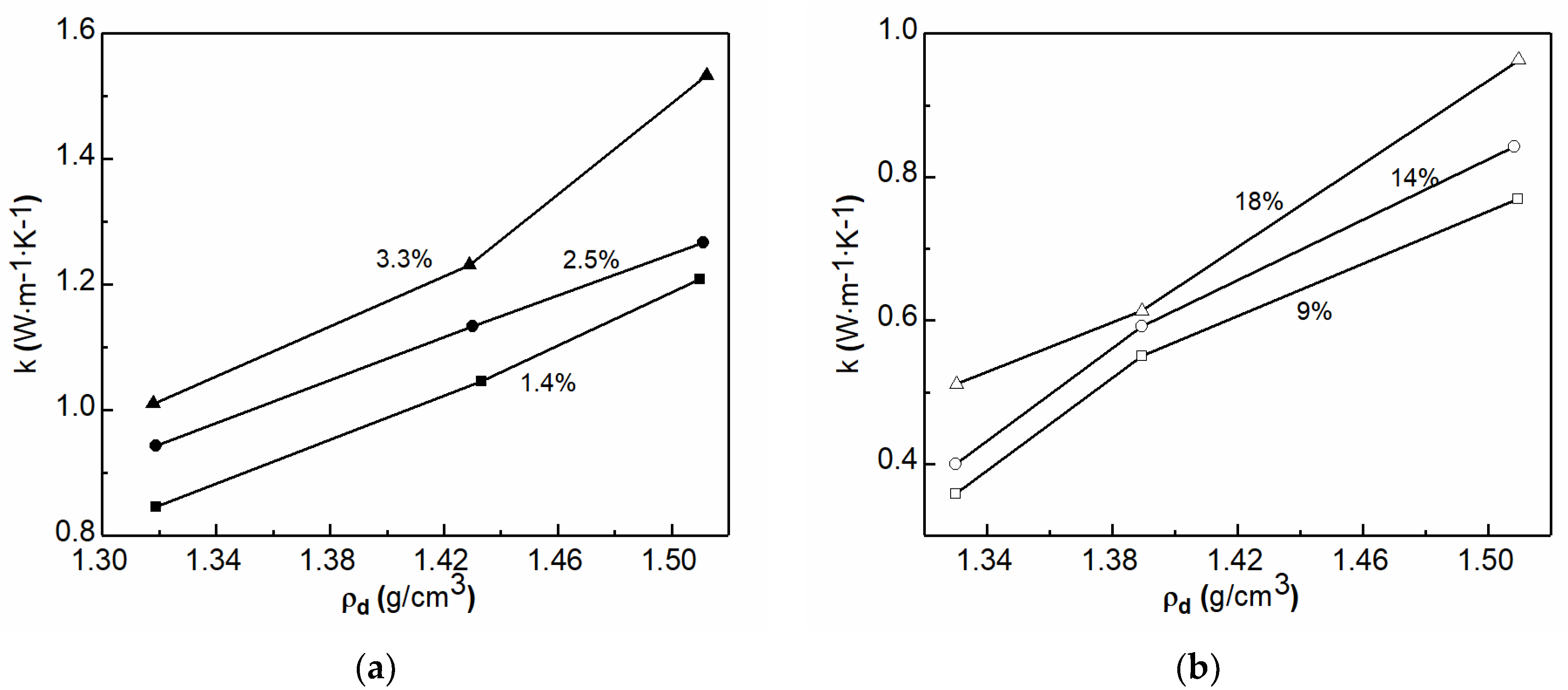
2.3.1. Water Content
2.3.2. Mineral Composition and Dry Density
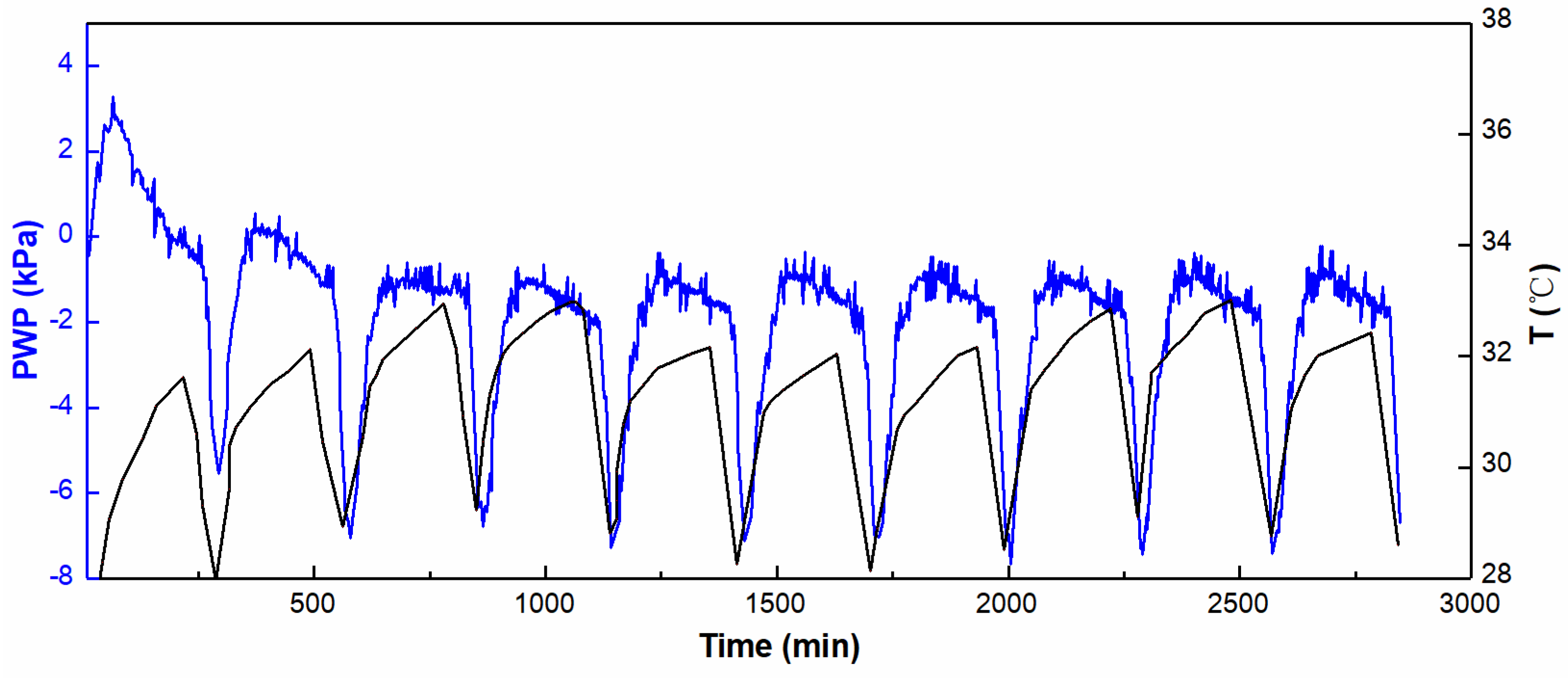
2.4. Long-Term Service
3. Numerical Simulations of GSHP Heat Transfer
4. Response under Thermo-Mechanical Coupling
4.1. Pile-Soil Interaction Mechanism
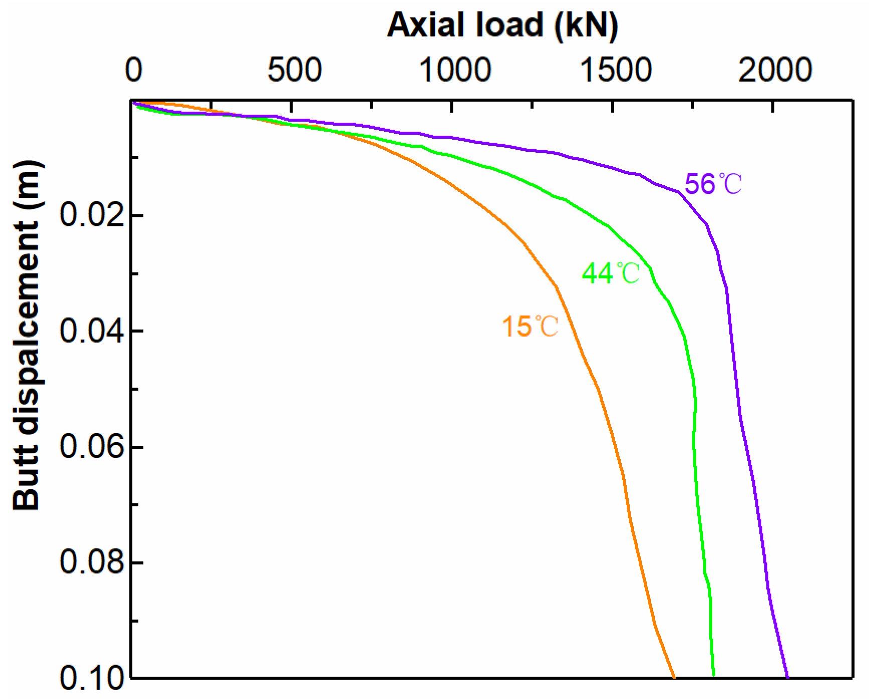
4.2. Bearing Characteristics of Energy Pile Groups
4.3. Simulations
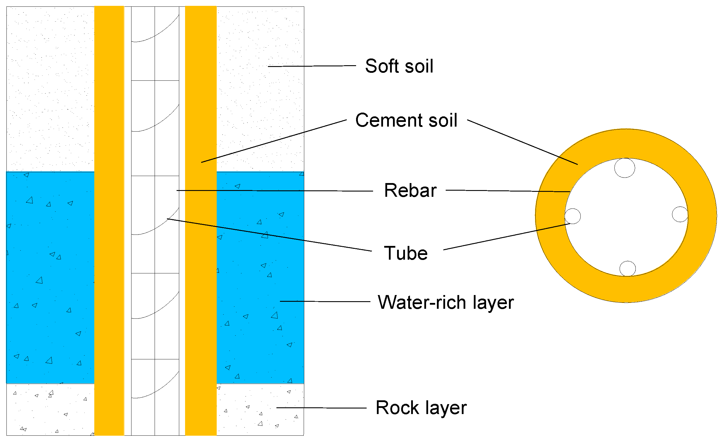
5. Applicability of Composite Energy Piles in Water-Rich Areas
6. Conclusions and Prospects
Author Contributions
Funding
Institutional Review Board Statement
Informed Consent Statement
Data Availability Statement
Conflicts of Interest
Appendix A

| Models | Mathematical Expression |
|---|---|
| Infinite line heat source [43] | |
| Finite line heat source [43] | |
| Hollow cylindrical heat source [44,45] | |
| 1-D heat source [44] | |
| 1-D heat source [44] |
| Nomenclature | |||
|---|---|---|---|
| heat capacity, J/(kg·K) | flow rate, kg/s | ||
| length of the tubes, m | thermal resistance, (m·K)/W | ||
| different of fluid temperature, °C | Euler’s constant | ||
| power per unit length, W/m | H | depth, m | |
| k | thermal conductivity, W/(m·K) | z | dimensionless axial coordinate |
| diameter, m | r | radial coordinate (m) | |
| Time, s | r0 | cylinder radius (m) | |
| thermal diffusivity, | |||
| R | |||
References
- Loveridge, F.; Mccartney, J.S.; Narsilio, G.A.; Sanchez, M. Energy geostructures: A review of analysis approaches, in situ testing and model scale experiments. Geomech. Energy Environ. 2020, 22, 100173. [Google Scholar] [CrossRef] [Green Version]
- Hamada, Y.; Saitoh, H.; Nakamura, M.; Kubota, H.; Ochifuji, K. Field performance of an energy pile system for space heating. Energy Build. 2006, 39, 517–524. [Google Scholar] [CrossRef]
- Liu, H.; Maghoul, P.; Bahari, A.; Kavgic, M. Feasibility study of snow melting system for bridge decks using geothermal energy piles integrated with heat pump in Canada. Renew. Energy. 2019, 136, 1266–1280. [Google Scholar] [CrossRef]
- Bidarmaghz, A.; Narsilio, G.A. Heat exchange mechanisms in energy tunnel systems. Géoméch. Energy Environ. 2018, 16, 83–95. [Google Scholar] [CrossRef]
- Kong, G.; Wu, D.; Liu, H.; Laloui, L.; Cheng, X.; Zhu, X. Performance of a geothermal energy deicing system for bridge deck using a pile heat exchanger. Int. J. Energy Res. 2018, 43, 596–603. [Google Scholar] [CrossRef] [Green Version]
- Buhmann, P.; Moormann, C.; Westrich, B.; Pralle, N.; Friedemann, W. Tunnel geothermics—A German experience with renewable energy concepts in tunnel projects. Géoméch. Energy Environ. 2016, 8, 1–7. [Google Scholar] [CrossRef]
- Lai, J.; Wang, X.; Qiu, J.; Zhang, G.; Chen, J.; Xie, Y.; Luo, Y. A state-of-the-art review of sustainable energy based freeze proof technology for cold-region tunnels in China. Renew. Sustain. Energy Rev. 2018, 82, 3554–3569. [Google Scholar] [CrossRef]
- Preene, M.; Powrie, W. Ground energy systems: From analysis to geotechnical design. Géotechnique 2009, 59, 261–271. [Google Scholar] [CrossRef]
- Noorollahi, Y.; Saeidi, R.; Mohammadi, M.; Amiri, A.; Hosseinzadeh, M. The effects of ground heat exchanger parameters changes on geothermal heat pump performance—A review. Appl. Therm. Eng. 2018, 129, 1645–1658. [Google Scholar] [CrossRef]
- Abuel-Naga, H.; Raouf, M.I.N.; Raouf, A.M.I.; Nasser, A.G. Energy piles: Current state of knowledge and design challenges. Environ. Geotech. 2015, 2, 195–210. [Google Scholar] [CrossRef]
- Fadejev, J.; Simson, R.; Kurnitski, J.; Haghighat, F. A review on energy piles design, sizing and modelling. Energy 2017, 122, 390–407. [Google Scholar] [CrossRef]
- Mohamad, Z.; Fardoun, F.; Meftah, F. A review on energy piles design, evaluation, and optimization. J. Clean. Prod. 2021, 292, 125802. [Google Scholar] [CrossRef]
- Yoon, S.; Lee, S.-R.; Xue, J.; Zosseder, K.; Go, G.-H.; Park, H. Evaluation of the thermal efficiency and a cost analysis of different types of ground heat exchangers in energy piles. Energy Convers. Manag. 2015, 105, 393–402. [Google Scholar] [CrossRef]
- Miyara, A.; Tsubaki, K.; Inoue, S.; Yoshida, K. Experimental study of several types of ground heat exchanger using a steel pile foundation. Renew. Energy 2011, 36, 764–771. [Google Scholar]
- Florides, G.; Christodoulides, P.; Pouloupatis, P. An analysis of heat flow through a borehole heat exchanger validated model. Appl. Energy 2012, 92, 523–533. [Google Scholar] [CrossRef]
- Florides, G.A.; Christodoulides, P.; Pouloupatis, P. Single and double U-tube ground heat exchangers in multiple-layer substrates. Appl. Energy 2013, 102, 364–373. [Google Scholar] [CrossRef]
- Gao, J.; Zhang, X.; Liu, J.; Li, K.; Yang, J. Numerical and experimental assessment of thermal performance of vertical energy piles: An application. Appl. Energy 2008, 85, 901–910. [Google Scholar] [CrossRef]
- Gao, J.; Zhang, X.; Liu, J.; Li, K.S.; Yang, J. Thermal performance and ground temperature of vertical pile-foundation heat exchangers: A case study. Appl. Therm. Eng. 2008, 28, 2295–2304. [Google Scholar] [CrossRef]
- Zarrella, A.; De Carli, M.; Galgaro, A. Thermal performance of two types of energy foundation pile: Helical pipe and triple U-tube. Appl. Therm. Eng. 2013, 61, 301–310. [Google Scholar] [CrossRef]
- Zarrella, A.; Capozza, A.; Carli, M.D. Analysis of short helical and double U-tube borehole heat exchangers: A simulation-based comparison. Appl. Energy 2013, 112, 358–370. [Google Scholar] [CrossRef]
- Luo, J.; Zhao, H.; Gui, S.; Xiang, W.; Rohn, J.; Blum, P. Thermo-economic analysis of four different types of ground heat exchangers in energy piles. Appl. Therm. Eng. 2016, 108, 11–19. [Google Scholar] [CrossRef]
- Park, S.; Lee, D.; Choi, H.-J.; Jung, K.; Choi, H. Relative constructability and thermal performance of cast-in-place concrete energy pile: Coil-type GHEX (ground heat exchanger). Energy 2015, 81, 56–66. [Google Scholar] [CrossRef]
- Yang, W.; Lu, P.; Chen, Y. Laboratory investigations of the thermal performance of an energy pile with spiral coil ground heat exchanger. Energy Build. 2016, 128, 491–502. [Google Scholar] [CrossRef]
- You, T.; Li, X.; Cao, S.; Yang, H. Soil thermal imbalance of ground source heat pump systems with spiral-coil energy pile groups under seepage conditions and various influential factors. Energy Convers. Manag. 2018, 178, 123–136. [Google Scholar] [CrossRef]
- Li, X.-Y.; Li, T.-Y.; Qu, D.-Q.; Yu, J.-W. A new solution for thermal interference of vertical U-tube ground heat exchanger for cold area in China. Geothermics 2017, 65, 72–80. [Google Scholar] [CrossRef]
- Cecinato, F.; Loveridge, F. Influences on the thermal efficiency of energy piles. Energy 2015, 82, 1021–1033. [Google Scholar] [CrossRef]
- Carotenuto, A.; Marotta, P.; Massarotti, N.; Mauro, A.; Normino, G. Energy piles for ground source heat pump applications: Comparison of heat transfer performance for different design and operating parameters. Appl. Therm. Eng. 2017, 124, 1492–1504. [Google Scholar] [CrossRef]
- Su, T.; Liu., T.; Li., X.; Yu, J.; Xiao, L. Test and analysis of thermal properties of soil in Nanjing district. Chin. J. Rock Mech. Eng. 2006, 25, 1278–1283. [Google Scholar]
- Leong, W.H.; Tarnawski, V.R.; Aittomäki, A. Effect of soil type and moisture content on ground heat pump performance. Int. J. Refrig. 1998, 21, 595–606. [Google Scholar] [CrossRef]
- Liu, C.; Zhou, D.; Wu, H. Measurement and prediction of temperature effects of thermal conductivity of soils. Chin. J. Geotech. Eng. 2011, 33, 1877–1886. [Google Scholar]
- Barry-Macaulay, D.; Bouazza, A.; Singh, R.M.; Wang, B.; Ranjith, P. Thermal conductivity of soils and rocks from the Melbourne (Australia) region. Eng. Geol. 2013, 164, 131–138. [Google Scholar] [CrossRef] [Green Version]
- Zhang, N.; Xia, S.; Hou, X.; Wang, Z. Review on soil thermal conductivity and prediction model. Rock Soil Mech. 2016, 37, 1550–1562. [Google Scholar]
- Cai, S.; Zhang, B.; Cui, T.; Guo, H.; Huxford, J. Mesoscopic study of the effective thermal conductivity of dry and moist soil. Int. J. Refrig. 2018, 98, 171–181. [Google Scholar] [CrossRef]
- Smits, K.M.; Sakaki, T.; Limsuwat, A.; Illangasekare, T. Thermal Conductivity of Sands under Varying Moisture and Porosity in Drainage–Wetting Cycles. Vadose Zone J. 2010, 9, 172–180. [Google Scholar] [CrossRef]
- Abu-Hamdeh, N.H.; Reeder, R.C. Soil Thermal Conductivity: Effects of Density, Moisture, Salt Concentration, and Organic Matter. Soil Sci. Soc. Am. J. 2000, 64, 1285–1290. [Google Scholar] [CrossRef]
- Becker, B.R.; Misra, A.; Fricke, B. Development of correlations for soil thermal conductivity. Int. Commun. Heat Mass Transf. 1992, 19, 59–68. [Google Scholar] [CrossRef] [Green Version]
- Angelotti, A.; Alberti, L.; La Licata, I.; Antelmi, M. Energy performance and thermal impact of a Borehole Heat Exchanger in a sandy aquifer: Influence of the groundwater velocity. Energy Convers. Manag. 2013, 77, 700–708. [Google Scholar] [CrossRef]
- Zhang, Y.-J.; Yu, Z.-W.; Huang, R.; Wu, G.; Hu, J.-H. Measurement of thermal conductivity and temperature effect of geotechnical materials. Chin. J. Geotech. Eng. 2009, 31, 213–217. [Google Scholar]
- Florides, G.A.; Kalogirou, S.A. Annual ground temperature measurements at various depths. In Proceedings of the CLIMA 2005, Lausanne, Switzerland, 9–12 October 2005. [Google Scholar]
- Bidarmaghz, A.; Narsilio, G.A.; Johnston, I.W.; Colls, S. The importance of surface air temperature fluctuations on long-term performance of vertical ground heat exchangers. Géoméch. Energy Environ. 2016, 6, 35–44. [Google Scholar] [CrossRef]
- Faizal, M.; Bouazza, A.; Wuttke, F.; Bauer, S.; Sanchez, M. Effect of forced thermal recharging on the thermal behaviour of a field scale geothermal energy pile. In Proceedings of the International Conference on Energy Geotechnics (ICEGT 2016), Kiel, Germany, 29–31 August 2016; Wuttke, F., Bauer, S., Sánchez, M., Eds.; CRC Press: Boca Rotan, FL, USA; pp. 557–568. [Google Scholar]
- Park, S.; Lee, S.; Oh, K.; Kim, D.; Choi, H. Engineering chart for thermal performance of cast-in-place energy pile considering thermal resistance. Appl. Therm. Eng. 2018, 130, 899–921. [Google Scholar] [CrossRef]
- Zeng, H.Y.; Diao, N.R.; Fang, Z.H. A finite line-source model for boreholes in geothermal heat exchangers. Heat Transfer-Asian Res. 2002, 31, 558–567. [Google Scholar] [CrossRef]
- Man, Y.; Yang, H.; Diao, N.; Liu, J.; Fang, Z. A new model and analytical solutions for borehole and pile ground heat exchangers. Int. J. Heat Mass Transf. 2010, 53, 2593–2601. [Google Scholar] [CrossRef]
- Wang, Z.; Shao, W.; Zhang, Y. Cylindrical surface model of ground source heat pump considering soil stratification. J. Zhejiang Univ. (Eng. Sci.) 2013, 47, 1338–1345. [Google Scholar]
- Adinolfi, M.; Maiorano, R.M.S.; Mauro, A.; Massarotti, N.; Aversa, S. On the influence of thermal cycles on the yearly performance of an energy pile. Géoméch. Energy Environ. 2018, 16, 32–44. [Google Scholar] [CrossRef]
- Diao, N.; Li, Q.; Fang, Z. Heat transfer in ground heat exchangers with groundwater advection. Int. J. Therm. Sci. 2004, 43, 1203–1211. [Google Scholar] [CrossRef]
- Fan, R.; Jiang, Y.; Yao, Y.; Shiming, D.; Ma, Z. A study on the performance of a geothermal heat exchanger under coupled heat conduction and groundwater advection. Energy 2007, 32, 2199–2209. [Google Scholar] [CrossRef]
- Molina-Giraldo, N.; Blum, P.; Zhu, K.; Bayer, P.; Fang, Z. A moving finite line source model to simulate borehole heat exchangers with groundwater advection. Int. J. Therm. Sci. 2011, 50, 2506–2513. [Google Scholar] [CrossRef]
- Lee, C.K.; Lam, H. A modified multi-ground-layer model for borehole ground heat exchangers with an inhomogeneous groundwater flow. Energy 2012, 47, 378–387. [Google Scholar] [CrossRef]
- Rivera, J.A.; Blum, P.; Bayer, P. Analytical simulation of groundwater flow and land surface effects on thermal plumes of borehole heat exchangers. Appl. Energy 2015, 146, 421–433. [Google Scholar] [CrossRef]
- Hu, J. An improved analytical model for vertical borehole ground heat exchanger with multiple-layer substrates and groundwater flow. Appl. Energy 2017, 202, 537–549. [Google Scholar] [CrossRef]
- Zhang, W.; Zhang, L.; Cui, P.; Gao, Y.; Liu, J.; Yu, M. The influence of groundwater seepage on the performance of ground source heat pump system with energy pile. Appl. Therm. Eng. 2019, 162, 114217. [Google Scholar] [CrossRef]
- Amatya, B.L.; Soga, K.; Bourne-Webb, P.J.; Amis, T.; Laloui, L. Thermo-mechanical behaviour of energy piles. Géotechnique 2012, 62, 503–519. [Google Scholar] [CrossRef]
- McCartney, J.S.; Murphy, K.D. Strain Distributions in Full-Scale Energy Foundations (DFI Young Professor Paper Competition 2012). DFI J. 2012, 6, 26–38. [Google Scholar] [CrossRef]
- Gashti, E.H.N.; Malaska, M.; Kujala, K. Evaluation of thermo-mechanical behaviour of composite energy piles during heating/cooling operations. Eng. Struct. 2014, 75, 363–373. [Google Scholar] [CrossRef]
- Bourne-Webb, P.J.; Amatya, B.; Soga, K.; Amis, T.; Davidson, C.; Payne, C. Energy pile test at Lambeth College, London: Geotechnical and thermodynamic aspects of pile response to heat cycles. Géotechnique 2009, 59, 237–248. [Google Scholar] [CrossRef]
- Laloui, L.; Nuth, M.; Vulliet, L. Experimental and numerical investigations of the behaviour of a heat exchanger pile. Int. J. Numer. Anal. Methods Géoméch. 2006, 30, 763–781. [Google Scholar] [CrossRef]
- Wang, C.-L.; Liu, H.-L.; Kong, G.-Q.; Wu, D. Model tests on thermal mechanical behavior of energy piles influenced with heat exchangers types. Eng. Mech. 2017, 34, 85–91. [Google Scholar]
- Wang, C.; Liu, H.; Kong, G. Influence of different stiffness constraints on stress and displacement of energy piles. Rock Soil Mech. 2018, 39, 4261–4268. [Google Scholar]
- Zhou, Y.; Zhao, D.; Li, B.; Tang, Q.; Zhang, Z. Fatigue Damage Mechanism and Deformation Behavior of Granite under Ultrahigh-Frequency Cyclic Loading Conditions. Rock Mech Rock Eng. 2021, 54, 4723–4739. [Google Scholar] [CrossRef]
- Laloui, L. Thermo-mechanical behaviour of soils. Rev. Franaise De Génie Civ. 2001, 5, 809–843. [Google Scholar] [CrossRef]
- Vardoulakis, I. Dynamic thermo-poro-mechanical analysis of catastrophic landslides. Géotechnique 2002, 52, 157–171. [Google Scholar] [CrossRef]
- Zhang, Y.G.; Xie, Y.L.; Zhang, Y.; Qiu, J.B.; Wu, S.X. The adoption of deep neural network (DNN) to the prediction of soil liquefaction based on shear wave velocity. Bull. Eng. Geol. Environ. 2021, 80, 5053–5060. [Google Scholar] [CrossRef]
- Yavari, N.; Tang, A.M.; Pereira, J.-M.; Hassen, G. Effect of temperature on the shear strength of soils and the soil–structure interface. Can. Geotech. J. 2016, 53, 1186–1194. [Google Scholar] [CrossRef]
- Akrouch, G.A.; Sánchez, M.; Briaud, J.-L. Thermo-mechanical behavior of energy piles in high plasticity clays. Acta Geotech. 2014, 9, 399–412. [Google Scholar] [CrossRef]
- Donna, A.D.; Ferrari, A.; Laloui, L. Experimental investigations of the soil–concrete interface: Physical mechanisms, cyclic mobilization, and behaviour at different temperatures. Can. Geotech. J. 2016, 53, 659–672. [Google Scholar] [CrossRef]
- Zeng, Z.; Lu, H.; Zhao, Y.; Qin, Y. Analysis of the Mineral Compositions of Swell-Shrink Clays from Guangxi Province, China. Clays Clay Miner. 2020, 68, 161–174. [Google Scholar] [CrossRef]
- Goode, J.C.; John, S.M. Centrifuge Modeling of End-Restraint Effects in Energy Foundations. J. Geotech. Geoenviron. Eng. 2015, 141, 04015034. [Google Scholar] [CrossRef] [Green Version]
- Kong, L.; Yao, Y. Thermo-visco-elastoplastic constitutive relation for overconsolidated clay. Rock Soil Mech. 2015, 36, 1–8. [Google Scholar]
- Hueckel, T.; Borsetto, M. Thermoplasticity of Saturated Soils and Shales: Constitutive Equations. J. Geotech. Eng. 1990, 116, 1765–1777. [Google Scholar] [CrossRef]
- Modaressi, H.; Laloui, L. A Thermo-Viscoplastic Constitutive Model for Clays. Int. J. Numer. Anal. Methods Geomech. 1997, 21, 313–335. [Google Scholar] [CrossRef]
- Cui, Y.; Sultan, N.; Delage, P. A thermomechanical model for saturated clays. Can. Geotech. J. 2011, 37, 607–620. [Google Scholar] [CrossRef]
- Yazdani, S.; Helwany, S.; Olgun, G. Investigation of Thermal Loading Effects on Shaft Resistance of Energy Pile Using Laboratory-Scale Model. J. Geotech. Geoenviron. Eng. 2019, 145, 04019043. [Google Scholar] [CrossRef]
- Fuentes, R.; Pinyol, N.; Alonso, E. Effect of temperature induced excess porewater pressures on the shaft bearing capacity of geothermal piles. Géoméch. Energy Environ. 2016, 8, 30–37. [Google Scholar] [CrossRef]
- Demars, K.R.; Charles, R.D. Soil volume changes induced by temperature cycling. Can. Geotech. J. 1982, 19, 188–194. [Google Scholar] [CrossRef]
- Krämer, C.; Basu, P. Performance of a model geothermal pile in sand. In Proceedings of the 8th International Conference on Physical Modelling in Geotechnics, Perth, Australia, 14–17 January 2014; Gaudin, C., White, D., Eds.; CRC Press: Boca Raton, FL, USA, 2014. [Google Scholar]
- Olgun, C.G.; Arson, C.F.; Ozudogru, T.Y. Thermo-mechanical radial expansion of heat exchanger piles and possible effects on contact pressures at pile–soil interface. Géotechn. Lett. 2014, 4, 170–178. [Google Scholar] [CrossRef] [Green Version]
- Liu, H.-L.; Wang, C.-L.; Kong, G.-Q.; Bouazza, A. Ultimate bearing capacity of energy piles in dry and saturated sand. Acta Geotech. 2018, 14, 869–879. [Google Scholar] [CrossRef]
- McCartney, J.S.; Rosenberg, J.E. Impact of Heat Exchange on Side Shear in Thermo-Active Foundations. In Proceedings of the Geo-Frontiers 2011: Advances in Geotechnical Engineering, Dallas, TX, USA, 13–16 March 2011. [Google Scholar]
- Loria, A.F.R.; Laloui, L. Thermally induced group effects among energy piles. Géotechnique 2017, 67, 374–393. [Google Scholar] [CrossRef] [Green Version]
- Murphy, K.D.; McCartney, J.S. Seasonal Response of Energy Foundations During Building Operation. Geotech. Geol. Eng. 2014, 33, 343–356. [Google Scholar] [CrossRef]
- Loria, A.F.R.; Laloui, L. The equivalent pier method for energy pile groups. Géotechnique 2017, 67, 691–702. [Google Scholar] [CrossRef] [Green Version]
- Salciarini, D.; Ronchi, F.; Cattoni, E.; Tamagnini, C. Thermomechanical Effects Induced by Energy Piles Operation in a Small Piled Raft. Int. J. Géoméch. 2015, 15, 04014042. [Google Scholar] [CrossRef]
- Sanner, B.; Mands, E.; Sauer, M.K. Larger geothermal heat pump plants in the central region of Germany. Geothermics 2003, 32, 589–602. [Google Scholar] [CrossRef]
- Ng, C.W.W.; Farivar, A.; Gomaa, S.M.M.H.; Shakeel, M.; Jafarzadeh, F. Performance of elevated energy pile groups with different pile spacing in clay subjected to cyclic non-symmetrical thermal loading. Renew. Energy. 2021, 172, 998–1012. [Google Scholar] [CrossRef]
- Saggu, R.; Chakraborty, T. Thermomechanical Response of Geothermal Energy Pile Groups in Sand. Int. J. Géoméch. 2016, 16, 04015100. [Google Scholar] [CrossRef]
- Wu, D.; Liu, H.-L.; Kong, G.-Q.; Waing, C.W.; Cheng, X.-H. Displacement response of an energy pile in saturated clay. Proc. Inst. Civ. Eng. Geotech. Eng. 2018, 171, 285–294. [Google Scholar] [CrossRef]
- Peng, H.-F.; Kong, G.-Q.; Liu, H.-L.; Abuel-Naga, H.; Hao, Y.-H. Thermo-mechanical behaviour of floating energy pile groups in sand. J. Zhejiang Univ. A 2018, 19, 638–649. [Google Scholar] [CrossRef]
- Loria, A.F.R.; Gunawan, A.; Shi, C.; Laloui, L.; Ng, C.W. Numerical modelling of energy piles in saturated sand subjected to thermo-mechanical loads. Géoméch. Energy Environ. 2015, 1, 1–15. [Google Scholar]
- Di Donna, A.; Laloui, L. Numerical analysis of the geotechnical behaviour of energy piles. Int. J. Numer. Anal. Methods Geomech. 2015, 39, 861–888. [Google Scholar] [CrossRef]
- Wuttke, F.; Bauer, S.; Sanchez, M. Energy Geotechnics||Numerical investigation of the mechanical behaviour of single energy piles and energy pile groups. In Proceedings of the International Conference on Energy Geotechnics, Kiel, Germany, 29–31 August 2016. [Google Scholar]
- Sarma, K.; Saggu, R. Implications of Thermal Cyclic Loading on Pile Group Behavior. J. Geotech. Geoenvironmental Eng. 2020, 146, 0420114. [Google Scholar] [CrossRef]
- Wonglert, A.; Jongpradist, P. Impact of reinforced core on performance and failure behavior of stiffened deep cement mixing piles. Comput. Geotech. 2015, 69, 93–104. [Google Scholar] [CrossRef]
- Voottipruex, P.; Suksawat, T.; Bergado, D.; Jamsawang, P. Numerical simulations and parametric study of SDCM and DCM piles under full scale axial and lateral loads. Comput. Geotech. 2011, 38, 318–329. [Google Scholar] [CrossRef]
- Tan, K.; Qin, Y.; Du, T.; Li, L.; Zhang, L.; Wang, J. Biochar from waste biomass as hygroscopic filler for pervious concrete to improve evaporative cooling performance. Constr. Build. Mater. 2021, 287, 123078. [Google Scholar] [CrossRef]
- Zhang, L.; Gustavsen, A.; Jelle, B.P.; Yang, L.; Gao, T.; Wang, Y. Thermal conductivity of cement stabilized earth blocks. Constr. Build. Mater. 2017, 151, 504–511. [Google Scholar] [CrossRef]
- Ashour, T.; Korjenic, A.; Korjenic, S.; Wu, W. Thermal conductivity of unfired earth bricks reinforced by agricultural wastes with cement and gypsum. Energy Build. 2015, 104, 139–146. [Google Scholar] [CrossRef]


| Reference | Tube Shape | Consideration | Methods | Performance Comparison |
|---|---|---|---|---|
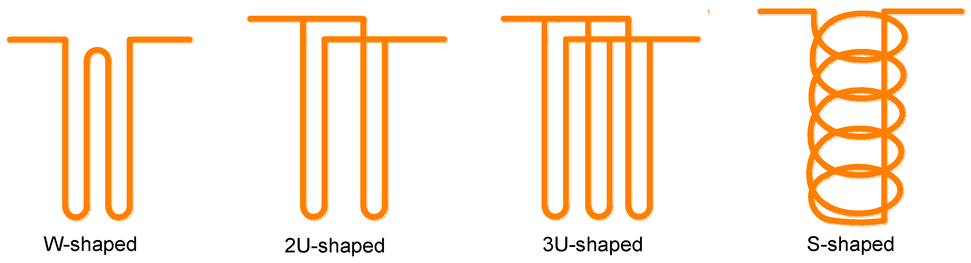
| Jalaluddin [14] | U-shaped, 2U-shaped, 3U-shaped | Ground temperature, wall temperature, velocity of fluid | Thermal response experiment | 2U-shaped > 3U-shaped > U-shaped |
| Florides [15,16] | U-shaped, 2U-shaped | Pipe size, soil thermal conductivity, soil stratification, cost | Numerical Simulation | 2U-shaped > U-shaped |
| Gao [17,18] | U-shaped, 2U-shaped, 3U-shaped, W-shaped | Circulating medium flow, inlet temperature, the unbalanced load of cold and heat, ground temperature | Thermal response experiment and numerical simulation | High flow: 2U-shaped > W-shaped > 3U-shaped > U-shaped Low flow: W-shaped > 2U-shaped > 3U-shaped > U-shaped |
| Zarrella [19] | 3U-shaped, S- shaped | helical pitch | Equivalent Circuit | S-shaped > 3U-shaped |
| Zarrella [20] | 2U-shaped, S-shaped | Axial heat conduction, drilling length, long-term and short-term heat transfer performance | Equivalent Circuit | S-shaped > 2U-shaped |
| Yoon [13] | W-shaped, S-shaped | The intermittent operation, cost, number of piles | Thermal response test and numerical simulation | S-shaped > W-shaped |
| Luo [21] | 2U-shaped, 3U-shaped, 2W-shaped, S-shaped | The intermittent operation, pipe size, cost | Thermal response test and numerical simulation | 3U-shaped > 2W-shaped, S-shaped > 2U-shaped |
| Model | Consideration | Inconsideration | Condition |
|---|---|---|---|
| line heat source model | Radial heat transfer | Geometry, internal heat transfer, tube shape | Constant heat flow, steady state |
| Hollow cylindrical heat source model | Geometry, thermal resistance | Geometry, thermal interference between tubes | Small diameter of piles, steady state |
| Solid cylindrical heat source model | The transient heat transfer | Thermal properties of concrete and soils | S-shaped tubes |
Publisher’s Note: MDPI stays neutral with regard to jurisdictional claims in published maps and institutional affiliations. |
© 2021 by the authors. Licensee MDPI, Basel, Switzerland. This article is an open access article distributed under the terms and conditions of the Creative Commons Attribution (CC BY) license (https://creativecommons.org/licenses/by/4.0/).
Share and Cite
Xie, J.; Qin, Y. Heat Transfer and Bearing Characteristics of Energy Piles: Review. Energies 2021, 14, 6483. https://doi.org/10.3390/en14206483
Xie J, Qin Y. Heat Transfer and Bearing Characteristics of Energy Piles: Review. Energies. 2021; 14(20):6483. https://doi.org/10.3390/en14206483
Chicago/Turabian StyleXie, Jinli, and Yinghong Qin. 2021. "Heat Transfer and Bearing Characteristics of Energy Piles: Review" Energies 14, no. 20: 6483. https://doi.org/10.3390/en14206483
APA StyleXie, J., & Qin, Y. (2021). Heat Transfer and Bearing Characteristics of Energy Piles: Review. Energies, 14(20), 6483. https://doi.org/10.3390/en14206483