Article

An Innovative Technology for Monitoring the Distribution of Abutment Stress in Longwall Mining

1
State Key Laboratory for Geomechanics & Deep Underground Engineering, China University of Mining & Technology, Beijing 100083, China
2
School of Mechanics and Civil Engineering, China University of Mining & Technology, Beijing 100083, China
*
Author to whom correspondence should be addressed.
Energies 2021, 14(2), 475; https://doi.org/10.3390/en14020475
Submission received: 21 November 2020 / Revised: 7 January 2021 / Accepted: 12 January 2021 / Published: 18 January 2021

Abstract

:
Fracturing roofs to maintain entry (FRME) is a novel longwall mining method, which has been widely used in China, leading a new mining revolution. In order to research the change law of side abutment pressure and movement law of overlying strata when using the FRME, a new abutment pressure monitoring device, namely, the flexible detection unit (FDU), is developed and is applied in the field. The monitoring results show that compared with the head entry (also called the non-splitting entry), the peak value of the lateral abutment pressure in the tail entry (also termed the splitting entry) is reduced by 17.2% on average, and the fluctuation degree becomes smaller. Then, finite difference software FLAC3D is used to simulate the stress change of the solid coal on both sides of the panel. The simulation results show that the side abutment pressure of the tail entry decreases obviously, which is consistent with the measured results. Comprehensive analysis points out that after splitting and cutting the roof, the fissures can change the motion state of the overlying strata, causing the weight of the overburden borne by the solid coal to reduce; therefore, the side abutment pressure is mitigated.

1. Introduction

The technology of gob-side entry retaining (GER) has been widely utilized worldwide since it was put forward in 1950s [1,2]. Compared with traditional mining methods, this technology has many merits, such as reducing the amount of roadway drivage, saving coal resources, alleviating dynamic mining disturbances, and so on [3]. At present, the common GER is to use high water materials, concrete blocks, gangue walls, and other filling bodies to support the roadway roof to isolate the connection between the roadway and the goaf, so that the roadway can be reused [4,5]. However, when the thick coal seam mining or rapid mining is carried out, the demand for filling materials will increase, and the formation speed of the filling body cannot match the speed of mining, so the roof cannot be supported in time. If the early deformation of the gateroad is serious, it will badly affect the use of the gateroad [6]. Based on this, an innovative GER approach is proposed, which can make fully use of the load-bearing capacity of gangue body to reduce periodic weighting load and improve the surrounding rock stress environment [7,8].
Many experts and scholars have conducted research on FRME, obtaining a series of rich results. He et al. [9] invented an energy-absorbing bolt with large elongation and high constant resistance. They introduced its structure and action mechanism in detail, and constructed a constitutive equation to derive the frictional resistance of the bolt during operation. Tao et al. [10] carried out a series of static tension tests on the constant resistance large deformation (CRLD) bolts. The results further indicated that the CRLD bolts had the characteristics of high support resistance, large elongation, absorbing energy, and negative Poisson’s ratio effect. Gao et al. [11] used COMSOL software to simulate and investigate bilateral cumulative tensile explosion technology (BCTET); they found that the cracks, created by explosions, could be propagated toward the set direction. However, there were no cracks in the non-set direction. Finally, a complete cutting line was formed between the blasting holes. Hu et al. [12] established a mechanical model for the unilateral crack propagation of the BCTET, and deduced the yield condition of crack formation. Guo et al. [13] implemented a great many axial compression tests on the novel gangue prevention structure in the laboratory, and the results suggested that the torque value of block cable was closely related to the axial force of the gangue prevention structure. Wang et al. [14] built a mechanical model of the retained entry roof according to the energy variational theory, and explored the factors that made the retained entry roof deform. He believed that the rotation of the main roof and the width of the entry had the most obvious influence on the roof deformation, and raised a method to control the roof deformation by designing a reasonable roof splitting height and roadway width. Fan et al. [15] set up a mechanical model of the FRME and studied the vertical stress and displacement of the coal wall under different heights and angles of the roof cutting through UDEC software. Guo et al. [16] simulated the dynamic response of the roof with different roof fracturing angles by FLAC3D for the first time. They considered that the dynamic response of the roof was moderate and the gateway remained stable when the roof splitting angle was 10–20°, and when the angle was 20–30°, the dynamic response increased obviously and the gateway became unstable. Sun and others [17] expounded the principle of the FRME to control rockburst. He believed that the FRME could reduce the vertical stress and stress fluctuation of gateway roof. He et al. [6] investigated the loads monitoring of hydraulic support at different positions on the panel of thick coal seams. The results testified that the loads of hydraulic support near the splitting line could be reduced by approximately 60% compared with that far away from the splitting line, at the same time, periodic weighting intervals of roof increased near the splitting line. The theses [18,19,20] demonstrated that the FRME could be applied under complex geological conditions.
The above papers discussed the surrounding rock deformation characteristics, engineering technical parameters, key technologies, roof control, and so on through the methods of numerical simulation, theoretical analysis, and field measurement. However, there are no analyses of the overlying strata movement after roof cutting and the changes of the abutment pressure caused by the strata movement. The changes of the abutment stress are the most crucial reason for the large deformation and instability of the entry. It is of great significance to research the changes of abutment stress for further understanding the deformation mechanism of surrounding rock of the FRME.
The purpose of this paper is to compare the difference of lateral abutment pressure between the tail entry and head entry by monitoring the abutment pressure of solid coal on both sides of the working face with self-developed and more reliable FDU, and then the influence of cutting seam on the lateral abutment pressure of solid coal is explored. On the basis of fully considering the reasons for the change of abutment pressure after cutting the roof, the change of overburden movement caused by the slit is analyzed.
At present, there is still no study on the abutment stress of the FRME. Taking the geological conditions of Lvtang Mine as the engineering background, this paper analyzes the side abutment stress of coal mass in the tail roadway and head roadway by self-developed FDU combined with numerical simulation, and explores the changes of abutment stress, so as to reveal the movement laws of overhanging rock.

2. Introduction of the FDU

2.1. Structure and Parameter of the FDU

The FDU consists of flexible shape (thin steel wire and polymer material composition), injection interface, plug, and iron sheet, as shown in Figure 1a. Its main technical specifications are as follows: the measurement range is up to 60 MPa, the length 500 mm, the diameter 45 mm, the accuracy from 0.5 to 1.0%FS, the repeatability from 0.2 to 0.4%FS, and the resolution 0.01%FS. The entity diagram of FDU is shown in Figure 1b.

2.2. Application Method of the FDU

The installation steps for the FDU are as follows: (1) Use a twist drill rod with a diameter slightly larger than that of the FDU to drill holes of different depth into the solid coal. (2) Connect the hand pump, pressure gauge and metal pipe together through the tee. (3) Fill the manual pump with emulsion and press it until one end of the metal tube flows out of the emulsion to discharge the air inside the metal tube. (4) Fill the emulsion from the injection interface of the FDU to drain the internal air. (5) Connect the metal tubes and FDU. (6) Slowly advance the unit to the bottom of the borehole, as illustrated in Figure 2a. (7) The manual pump continues to press, and this process should ensure that the pressure increases steadily until the pressure gauges read 5.25 MPa and maintain for 30 min. At this time, the units expand to fit the hole wall, as shown in Figure 2b. (8) Relieve the pump pressure and observe the changes of the pressure gauge reading. If the reading cannot be stabilized at the preset initial pressure value, then step 7 should be repeated until the initial pressure reaches a stable level. (9) Debug the transmission substation and the master station to ensure that the pressure gauge data can be transmitted to the ground computer in time and accurately.

2.3. Working Principle of the FDU

At present, it is common that borehole stress meters are made of rigid materials and can only monitor the abutment pressure at a certain point or a certain face. There are no measurement data in the elastic deformation phase of coal caused by the installation clearance of rigid materials, as illustrated in Figure 3a. The objective of the FDU is to monitor the whole changes of abutment pressure in coal. Its working principle is shown in Figure 3b. After the liquid at a certain pressure injected into the FDU, it will expand, which can generate a pre-tightening force to the borehole surroundings. As the stoping face advances, the abutment pressure will move forward, causing the borehole surroundings to deform and break under the influence of dynamic pressure. Therefore, when the FDU is squeezed into different degrees, the internal liquid pressure will change clearly. Those pressure changes will be transmitted to the wireless pressure sensor through metal pipe, and the strain gauge on the elastomer of the sensor will change its value after being pressed, causing the change amount of the electrical signal to amplify. Then, the amplifying signal will be converted into a voltage signal after driven by the sensor. Finally, the CPU will convert the voltage signal into the pressure value and display it on the pressure gauge. Meanwhile, the pressure value will real-timely be transfer to the transmission substation through wireless communication, which will upload to the ground computer via optical cable.
The main structures of the abutment pressure monitoring system are mainly made up of five parts: FDU, pressure gauges, transmission substations, transmission main station, and computer. The working principle of the abutment pressure monitoring system is shown in Figure 4. The FDU, in real-time, can monitor the pressure changes of the surrounding rock in the coal body. The pressure gauge can transmit the pressure value to the transmission substation by wireless signal every 5 min. Each substation can receive the signals of multiple pressure gauges at the same time, and it can transfer the received singles to the main transmission station through the line. The main station can simultaneously process the singles of several substations, and then transmit all the information to the ground transmission interface with the optical fiber. Finally, through the independently developed software system in the computer, the observed data can be displayed in forms of curve and chart. Then, the observed data can be showed to users graphically through the Internet, which is convenient for users to analyze and view them in real-time and remotely.

2.4. Principle of the FRME

The implementation procedure of the FRME can be divided into four parts, which are illustrated in Figure 5. Before the mining of the working face, CRLD anchor cables are constructed in the roadway to strengthen the roof, so as to prevent the disturbance of the roadway roof caused by the subsequent roof pre-split blasting and the roof collapse in the goaf, as shown in Figure 5a. Then, the structure of the blasting holes is implemented on the side of the working face in the tail entry according to the designed height, angle, and distance between the blasting holes. Sequentially putting the cumulative energy explosion tubes [11,19], the emulsified blasting powders, detonators, and the stemming into the blasting holes to form a continuous fracturing line along the axis of the roadway, as shown in Figure 5b. After the mining of the panel, the goaf side of the roadway roof will cave automatically along the splitting face under the action of the mine pressure. Then, the gangue of different size and shape will be formed in the process of roof collapse. Meanwhile, in order to prevent the gangue from rushing into the entry in the process of fall and compaction, U-shaped steels, metal meshes, and single hydraulic pillars beside the entry can be used to block the gangue, as shown in Figure 5c. In this way, the compacted gangue can be used as a side of the entry to continue to serve for the mining of the next panel, as shown in Figure 5d. The three-dimensional schematic diagram of the FRME is shown in Figure 6.

3. Methods

3.1. Method of Numerical Analysis

3.1.1. Study Site

Lvtang Coal Mine is located in Bijie area, Guizhou Province, China. This article analyzes the actual engineering geological conditions according to S204 working face of Lvtang Coal Mine. This panel is the first panel in this mining area, and the adjacent working faces are represented by the S205 and S203 panels. The average strike length of S204 panel is 310 m and the dip length is 115 m. The dip angle of coal seam is 3–9°, with an average of 6°. The thickness of coal seam is 0.9–7.55 m, with an average thickness of 3.4 m. The layout of panels is shown in Figure 7. The mine belongs to coal and gas outburst mine. In order to reduce the gas concentration to achieve safe mining, it is necessary to excavate a gas drainage roadway above the working face to extract gas from the coal before mining. It is planned to use FRME in tail entry, and the head entry will naturally fall.
The average buried depth of S204 mining panel is 210 m. The geological drilling picture of the S204 panel is shown in Figure 8. The roof strata above the S204 face are mainly composed of silty mudstone and muddy siltstone, and the floor stratum are made up of silty mudstone, coal, and muddy siltstone. It can be seen from the stratigraphic column that the lithology of the roof and the coal seam changes greatly.

3.1.2. Numerical Modal

According to the symmetrical characteristic of the model, in order to shorten the calculation time, the strike length of the model is shortened to become half of the actual engineering geological conditions. The work in [21] also employs the symmetry principle for numerical simulation. At the same time, in order to eliminate the influence of boundary conditions, 60 m boundary coal pillars are added on the left and right sides of the model. This model is divided into 8 layers, and the size (length × width × height) is 244 m × 160 m × 50 m. The Mohr–Coulomb criterion is used in the model. Constraints are imposed on the surrounding and bottom surfaces to restrict its movement. The stress of 5.25 MPa is applied on the upper surface to simulate the weight of the overlying rock. According to the geological situation of S204 coalface in Lvtang Coal Mine, a three-dimensional numerical model is established as shown in Figure 9.
The splitting surface is an abstract simulation of the blasting effect. Because the distance between these blast holes is extremely close and they can penetrate each other after blasting, the blast holes and slit between them can be simplified to dispose, which can be regarded as a fissure surface composed of uniform blocks in numerical model. The length of the on-site blast holes is 8 m and the angle is 15°; therefore, the length of the fissure surface is also 8 m, the angle is 15°, and both the width and the diameter of the blast holes are 48 mm. The blasting is simulated by excavating the fissure face.
The mechanical parameters of each rock mass are shown in Table 1. Among them, the parameters of coal body and roof rock are obtained by GSI rock mass classification method on the basis of rock mechanics parameters obtained by laboratory uniaxial compression test and field borehole peep to estimation GSI value. The parameters of floor sandy mudstone are obtained by GSI rock mass classification method based on the measured mechanical parameters of coal mine exploration.

3.2. Method of Field Measurement

In order to discuss and investigate the evolution laws of the side abutment stress in the tail entry and head entry and the influence of the fracture and movement of overlying strata on gateway stability after using the FRME, 12 sets of the FDU were installed in the solid coal of the head entry and tail entry of 100 m in front of the coalface to monitor the changes of coal mass stress, independently. The installation depth of the FDU is different, because the authors of [21,22,23] found that the load-bearing capacity of coal is related to the distance from the coal wall. The distances between the installation position of the FDU and the gateway surface are 3 m, 5 m, 7 m, 9 m, 11 m, and 13 m, as shown in Figure 10a. According to the actual situation of the mining face, the twist drill pipes with a diameter of 48 mm are selected to drill the holes, which are perpendicular to the coal wall and 1 m away from the gateway floor, as shown in Figure 10b.

4. Data Analysis of the Abutment Stress

4.1. Data Analysis of the Field Measurement

4.1.1. Monitoring Result of the Strike Abutment Stress

Stations 1# and 2# started to be installed at 200 m in front of the working face from 1 August 2019. Due to the need of coal mining and the restriction of construction, the installation was officially completed and connected network single at about 100 m in front of the working face on 16 August. Therefore, the pressure changes of the previous FDU were not recorded in time. The pressure variations were only recorded when the signal was switched on. The unit’s pressure had been recorded until 15 September at 100 m behind the working face. The strike abutment pressure monitoring curve of the stations 1# is shown in Figure 11.
The abutment pressure at the 3 m position of the station 1# rises the slowest, and the increasing trend is not obvious, which is likely that the coal mass in this range was yielded or even destroyed by the strong abutment pressure, so its bearing capacity is smaller. The variation tendencies of the strike abutment pressure at 5–13 m are the same, showing a state of increasing first, then decreasing and then increasing, and finally stabilizing. However, the speed and amplitude of the strike abutment pressure growth within the range of 100 to 20 m in front of the working face increases in turn with the increase of the coal depth.
About 20 m in front of the panel, the strike abutment stress at 5–13 m decreased rapidly, and the degree of stress fluctuation is large. This is because that as the longwall face approaces the FDU, a concentration area of abutment pressure will be formed ahead of the face, where the abutment pressure will be transmitted to the coal rib through the roof, where the stress concentration zone will be formed, causing the plastic failure of the coal mass. With the advancement of the longwall face, the failure will continue to develop deeper. Finally, a plastic zone with a length of about 20 m is formed on the coal rib, as a result, the carrying capacity of the solid coal is weakened [24]. After the longwall face pushes through the units, the strike abutment stress at 3–13 m grows slowly with the increase of the longwall face distance; in the meantime, the rising trend is almost the same as the amplitude. This is because the weight of the overburden on the longwall face is shifted after the coal seam is mined to the solid coal on both sides of the face and the gangue falling in the goaf, so the solid coal begins to slowly increase in stress. It should be mentioned that the irregular fluctuation of the abutment pressure behind the longwall face belongs to the stress fluctuation that is caused by the periodic collapse of the goaf roof.
The monitored distance of the abutment pressure at 2# station in the tail entry is the same as that of 1# station in the head entry. However, the abutment pressure has changed significantly. Strike abutment pressure curve of station 2# in the tail entry is illustrated in Figure 12.
The change trend of the strike abutment pressure at the 5–13 m measurement points of solid coal in the roof-cutting roadway (tail roadway) is also the same as the roof-noncutting roadway (head roadway), showing a state of increasing first, then decreasing and then increasing, and finally stabilizing. When the FDU is located more than 60 m in front of the working face, the abutment pressure at different measuring points of the 2# station increases slowly, and the curve is relatively stable. This indicates that when the distance of coal body is over 60 m in front of the working face, it is affected slightly by mining pressure. When the FDU is located in the range of 60 to 10 m in front of the working face, the abutment pressure at 5–13 m of station 2# begins to increase rapidly, reaching a maximum value about 10 m in front of the working face. The growth rate of the abutment pressure at 9–11 m is obviously greater than that of other depths, indicating that the coal body in this range is very susceptible to the impact of mining pressure. Moreover, the abutment pressure at 9 m is always greater than that of other depths.
When the FDU is from 10 m in front of the working face to near the working face, the abutment pressure of each measuring point drops rapidly, which is related to the mining of the working face. When the FDU is from near the working face to 60 m behind the working face, the abutment pressure of each measuring point increases slowly. When the lagging face of the FDU exceeds 60 m, the abutment pressure remains stable.
However, we discover that there are several differences in the strike abutment pressure curve of each measuring point between the two stations:
(1)
The peak value of strike abutment stress at each measuring point of station 2# has been reduced, with an average diminishment of 17.2%.
(2)
The peak point of strike abutment stress at each measuring point of station 2# is closer to the longwall face.
(3)
After the stope face pushed pass the units, the abutment pressure at each measuring point of the station 2# increases steadily, unlike the violent fluctuation of the abutment pressure occurs at the measuring point of station 1#, indicating that the periodical pressure of the stope face on the tail roadway weakens.
(4)
The abutment pressure at the 9 m measuring point of station 2# is the highest, at the same time, the abutment pressure of each measuring point generally enlarges at first and then decreases as the depth from the coal wall increases.
The variation trend of the strike abutment pressure at each measuring point of station 2# is almost the same as that of station 1#. Therefore, the strike abutment pressure of the solid coal can be divided into 5 regions: slow increasing zone I, sharp increasing zone Ⅱ, rapid reducing zone III, fluctuation enlarging zone (enlarging zone) Ⅳ, and stable zone Ⅴ.
Slow increasing zone I: in this area, from the beginning position of the abutment pressure rise to 55 m in front of the working face, the stress increases slowly, and the abutment pressure curve is relatively smooth. At this time, the deformations of the entry surroundings are also relatively small, and the influence of the advanced abutment pressure on solid coal is not obvious.
Sharp increasing zone Ⅱ: abutment pressure from about 55 m to 15 m in front of the face goes up rapidly, and the alteration of the abutment stress curve becomes steep. At this time, the deformations of the roadway surroundings get extremely remarkable, which is obviously affected by the advanced abutment pressure.
Rapid reducing zone III: the stress decreases sharply from about 15 m in front of the panel to near the longwall face. At this time, the deformation and its rate of the roadway surrounding rock is relatively great. The coal body on the side of the solid coal in the entry is plastically damaged, and cracks and holes appear in the internal coal mass. The coal releases stress and the abutment stress start to reduce.
Fluctuation enlarging zone (enlarging zone) Ⅳ: this area extends from the vicinity of the longwall face to 60 m behind the working face. The abutment stress shows a state of fluctuation increase. This is due to the roof behind the working face periodically breaks under the action of periodic pressure.
Stability zone Ⅴ: the stress fluctuation is not obvious in 60 m behind the working face in this area and the curve becomes a stable straight line. It suggests that when the lagging distance of coal face is greater than 60 m, the overlying rock has been stabilized.

4.1.2. Monitoring Result of the Side Abutment Stress

In order to analyze the abutment pressure distribution of the coal mass with different depths at the side of solid coal in the tail entry and head entry and the relationship between the side abutment pressure and the working face distance, the average value of the pressure gauge reading of each unit at 60 m, 40 m, and 20 m in front of and behind the mining panel is taken, respectively, to draw the pressure histograms. Figure 13 shows that the abutment pressure distribution of coal mass with different depths at the side of solid coal in the tail entry and head entry and the relationship between the side abutment pressure and the working face distance.
From Figure 13a,b, we can see that when the stations are in front of the working face, the lateral abutment pressure on both sides of panel increases first then declines as the depth changes. The peak point of the lateral abutment pressure in the tail roadway and head roadway is 9 m and 11 m away from the coal wall, respectively. Therefore, the rising range of lateral abutment pressure in the head entry is larger than that of the tail entry. At the same time, compared with the head entry, the peak value of the lateral abutment pressure is smaller in the tail entry, indicating that roof cutting can play a good effect in stress relieving. The closer the FDU is to the working face, the greater the lateral abutment pressure will become, which suggests that the lateral abutment pressure is in the process of dynamic change and has obvious space-time effect [23].
Figure 13c,d shows that when the measuring stations are behind the coalface, the farther the distance from the same measuring point to the coalface is, the higher the recovery degree of the abutment pressure will become, which is related to the transfer of overburden weight to solid coal on both sides of face after coal seam mining [25]. The lateral abutment pressure of the tail roadway climbs up first and then declines, while the lateral abutment pressure of the head roadway shows an increasing trend which has no obvious regularity. Compared with the head roadway, the lateral abutment pressure of the tail roadway in the back of coalface under the same distance is generally smaller.
The lateral abutment stress of the tail roadway reaches the maximum at 9 m from the coal wall, and its rising range of 7–9 m from the coal wall is obviously larger than that of 3–7 m in the process of lateral abutment pressure rising. In contrast, in the head roadway, the lateral abutment pressure at a distance of 3 m to 5 m from the coal wall first decreases slightly, then it at a distance of 5 m to 13 m from the coal wall has been increasing, whereas, the increasing rate in this range is not in agreement, which slows down when it is away from the coal wall (5–9 m) and begins to accelerate when it is away from the coal wall (9–13 m).
Variation curve of lateral abutment peak position is shown in Figure 14. We can find that the lateral abutment pressure of the two roadways constantly alters, and the peak position continuously deepens from coal mass. In the end, there will be no change at a certain depth.
Nonetheless, we can also see that there is a significant difference of the lateral abutment pressure in two roadways. The lateral abutment pressure of the head entry has experienced three-step fluctuations to reach stability, while the lateral abutment pressure of the tail roadway goes through two steps to reach a stable state, and a small fluctuation degree is more conducive to maintaining the entry stability, which proves that the slit can change the structure of the roadway roof. As a result, when the technology of the FRME is employed, the solid coal is less affected by the breaking and collapsing gob roof.

4.2. Data Analysis of the Numerical Modal

During the simulated excavation, in order to best meet the reality, we first simulated the excavation of the two entries, then supporting measures of the entries were installed until the calculation reaches the balance, after that the splitting face was mined to simulate blasting. In the end, the simulated exploiting of the mining panel was carried on. The excavation length of the mining panel was 5 m each time, and it was mined a total of 32 times. The cumulative lengths of 40 m and 80 m were selected to research the change laws of side abutment pressure of the FRME.
The three-dimensional cloud maps of the abutment stress distribution in the surrounding rock at the coal face are shown in Figure 15.
From the three-dimensional cloud maps, we can deem that the overall stress will change after the panel is mined. When the roof of mined out area has not completely caved in, the pressure relief area (blue area) is formed. Only if the gob roof collapses fully and caved-rock is compacted by the overlying strata, the stress in the goaf starts to increase slowly. After the mining of the face, the weight of the overhanging rock is supported by the gangue in the goaf, the coal body in front of the panel, and the solid coal on both sides of the roadway, where the stress augments distinctly. When the FRME technology is not used in the tail entry, after 40 m or 80 m excavation of the working face, symmetrical stress concentration areas appear in the solid coal on both sides of the working face (see Figure 15a,b). While, when the tail entry adopts the FRME technology, after the working face is excavated to 40 m or 80 m, due to the blocking effect of the slit, asymmetrical stress concentration areas appear in the solid coal on both sides of the working face (see Figure 15c,d).
The side abutment pressure of the tail roadway with the roof splitting is significantly lower than that of the head roadway without the roof splitting. The simulation result displays that the peak value of lateral abutment pressure in tail roadway without the roof cutting is around 22.4 MPa. After using the technology of the FRME, the peak value of lateral abutment pressure in tail roadway with the roof cutting is reduced to 18.3 MPa, which is reduced by 18.3%.
Moreover, compared with the average lateral abutment stress in head roadway without roof cutting, the average lateral abutment stress of the tail roadway with roof cutting is also reduced by 18.3%. The technology of the FRME can change the stress state in the surrounding rock and have an excellent pressure relieving effect, which has positive significance to maintain the stability of tail roadway.
After increasing the length of the boundary coal pillar, we can more intuitively observe the influence range of lateral abutment pressure. When the roof is not cut, the lateral abutment pressure in the solid coal of the tail entry returns to the original rock stress at 47 m (see Figure 15a,b). After cutting the roof, the lateral abutment pressure in the solid coal of the tail entry is restored to the original rock stress at 35 m, and the influence range of the lateral abutment pressure is reduced by 25.5% (see Figure 15c,d).
After pre-cracking the roof, the reduction of the lateral abutment pressure of the tail entry is closely related to the slit. The cutting fissure can block the connection between the goaf roof and the entry roof; therefore, the stress of the goaf roof cannot be transmitted to the solid coal of the roadway. In the meantime, the cutting seam can shorten the length of the side roof of the gob-sides in the entry. When the main roof rotates and sinks after the mining of the working face, the deformation degree of extrusion to the roadway roof will be significantly reduced. These are the two main reasons for the decrease of lateral abutment pressure in the tail entry after pre-splitting the roof.
In order to further explain the technical advantages of the FRME, the models with the working face mining to 40 m and 80 m were selected for analysis and sliced along the bottom of the entry to explore the changes in lateral abutment pressure. We can clearly see that when the FRME technology is not used in the tail entry, the lateral abutment pressure presents symmetrical distribution all the time with the advancement of the working face, as shown in Figure 16a,b. When the FRME technology is used in the tail entry, the lateral abutment pressure on both sides of the working face has changed significantly. When the working face advances to 40 m, the stress concentration area on the solid coal of the head entry is closer to the head entry, while the stress concentration on the tail entry side is not obvious, and the abutment pressure is 18.4 MPa, as shown in Figure 16c. When the working face advances to 80 m, the stress concentration area on the solid coal of the head entry tends to be far away from the head entry, and the abutment pressure of the tail entry is about 20 MPa, which is bigger than the mining distance of 40 m, as shown in Figure 16d.
This phenomenon shows that the lateral abutment pressure increases with the increase in the distance of the lagging working face, which is closely related to the movement of the overburden. The farther the distance from the lagging working face is, the more sufficient the movement of the overburden is and the greater the weight of the overburden carried by the solid coal is, the larger the lateral abutment pressure is.
Figure 17 shows that with the face advancing to 80 m, a plastic failure zone with the width of 11 m and advanced working face of 17 m is formed in the solid coal of the head roadway (see Figure 17a), while a plastic failure zone of 9 m in width and 9.5 m in front of working face is formed in the solid coal of the tail roadway (see Figure 17b). The length and width of the plastic failure zone in the slotted entry is smaller than that in the unslotted entry.
After pre-splitting and cutting the roof, the influence of coal mining on the solid coal in the tail entry is lessened; that is, the fissure changes the movement state of the overlying rock, so that the weight of the overburden rock supported by the solid coal is reduced. Therefore, the concentration degree of stress is lower, and the impact by upper strata on the coal body becomes smaller. On the other hand, the movement state of the overlying rock on the side of the unslotted head entry has not changed. The weight of the overburden rock born in the solid coal of the head entry is relatively larger, and the concentration degree of stress is higher, which has a greater impact on the coal body.

5. Discussion of Overburden Movement

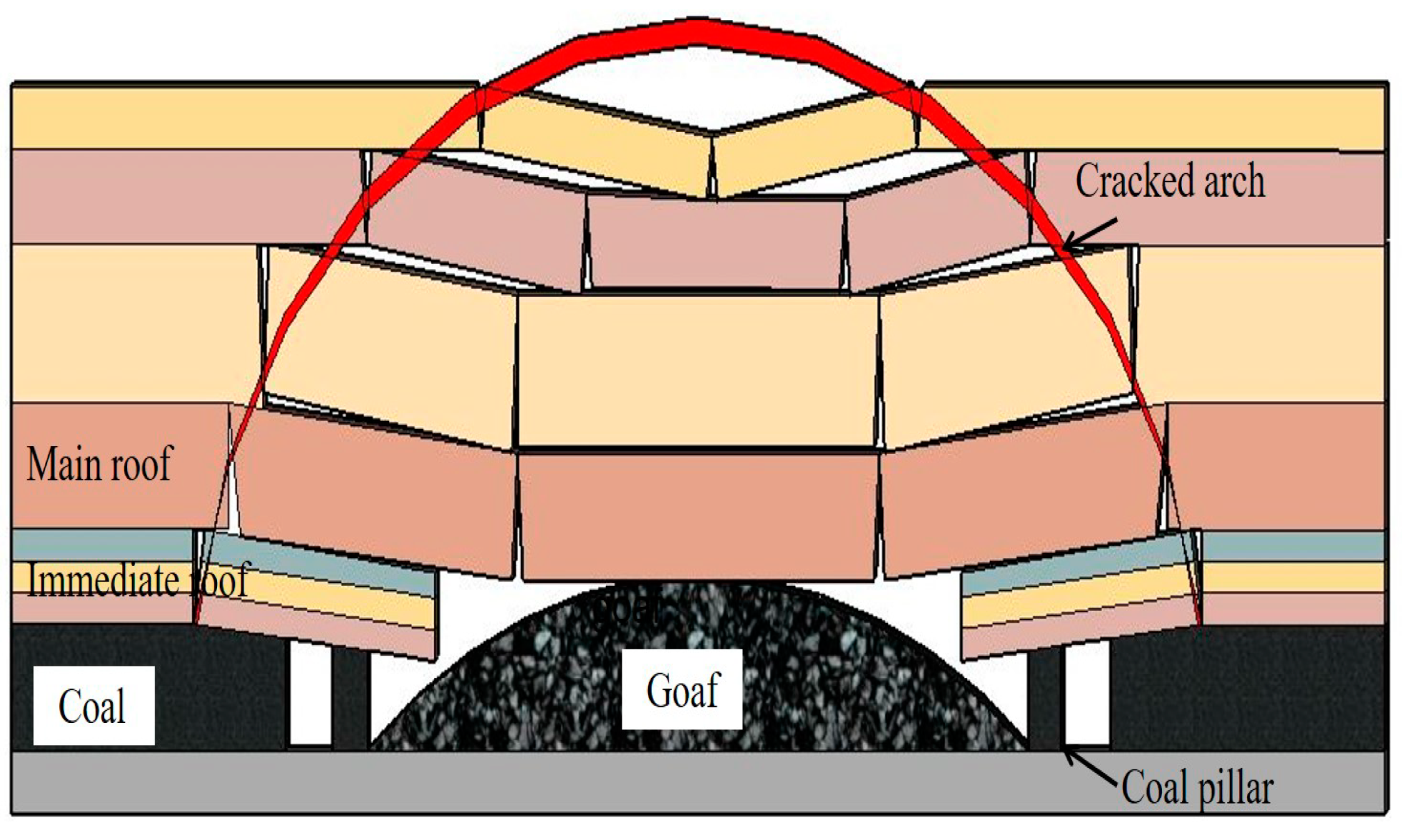
5.1. Overburden Movement Status in Traditional Coal Pillar Mining

In view of the difference of the abutment pressure at each measuring point between the two stations, we believe that the cutting seam is the main reason for this phenomenon, because the formation of the splitting face can make the roof in the mined-out area collapse more fully, which affects the motion state of the entire coal face roof [26].
As shown in Figure 18, in traditional mining, after the coal seam is mined, the gob roof is difficult to collapse insufficiently. Therefore, the goaf is incompletely filled by the falling gangue. There is large space above the goaf, where the main roof can continue to go down, and when the tensile strength limit is reached, the breakage of the main roof occurs, which generates dynamic pressure impact on the roadway and in turn affects side abutment pressure.
In traditional mining, after the coal seam is mined, the gob roof is difficult to collapse insufficiently. Therefore, the goaf is incompletely filled by the falling gangue. There is large space above the goaf where the main roof can continue to go down, and when the tensile strength limit is reached, the breakage of the main roof occurs, which generates dynamic pressure impact on the roadway and in turn affects side abutment pressure. In the meantime, the rotation and subsidence of main roof will squeeze the side roof of the gob-sides, creating a stress concentration zone in the solid coal, and the abutment pressure is further increased. The movement of the rock strata will continue to develop upward. If the upper stratum also fractures, it will once again impact the solid coal of the roadway, causing the weight of the overlying strata borne by the solid coal on both entries will be further rising, while the goaf gangue only bears a small part of the weight of the overlying rock. Therefore, the abutment pressure on the solid coal will increase significantly, and this process continues until the overburden layer only bends and sinks without breaking. The abutment pressure of the solid coal increases, then the destruction degree of the coal body enlarges, creating a large distance between the plastic zone and mining panel. Therefore, the peak point of the abutment pressure is far away from the mining panel. The literature [20,27] believe that the abutment pressure reaches the maximum at the end of plastic failure (the elastic-plastic junction).

5.2. Overburden Movement Status in the FRME

Figure 19 shows that after splitting and cutting the roof, the immediate roof of the goaf in the range of roof-cutting height collapses smoothly under the action of mine pressure and the broken cantilever beam will further fill the gob, which makes the expansion coefficient of gangue augment. The gangue can rapidly connect with the main roof, and it will have a certain bearing capacity to support the main roof after being squeezed by it. Therefore, the space for the main roof to continue sinking is very small, which can prevent the overlying strata from further breaking. Simultaneously, the rotation and subsidence degree of the main roof will be reduced or even disappeared. On the one hand, the weight of the overburden borne by the solid coal is reduced. On the other hand, the extruded gangue has an inclined force on the roof of the retained roadway. As a result, the side abutment pressure of the solid coal must markedly decrease. In addition, the slit can cut off the stress transmission between the entry roof and the goaf roof, and this will avoid the transmission of dynamic loads in the goaf to the solid coal, which is also one of the reasons for the reduction of the side abutment stress. The reduction of abutment pressure will result in the decrease of coal damage degree, and the range of the plastic zone will decrease. Therefore, the peak point of the abutment pressure will be closer to the coal face.
The differences in the research on abutment pressure between this paper and the previous papers are shown as follows.
Yan et al. [25] discussed the influence range of lateral abutment pressure in coal pillar under the traditional mining mode through numerical simulation, but did not study the change of abutment pressure when using the FRME. The FRME is an innovative technology for the GER, the study of its lateral abutment pressure can not only fully understand this technology, but also better explain the advantages of the FRME over the traditional mining technology. Zhen et al. [28] compared and analyzed the difference of abutment pressure between traditional mining and the FRME through numerical simulation. However, they did not explore the reasons for this difference in depth. Based on field measurement, this paper considers that the overburden movement is the root cause of the difference in abutment pressure under different mining conditions. The state of overburden movement when using the FRME is described in detail, and the factors of abutment pressure reduction are analyzed from many aspects. Yao et al. [29] discussed the lateral abutment pressure by means of numerical simulation and borehole stress measurement, but did not analyze the lateral abutment pressure in the direction of the coalface strike. On the basis of the FDU field measurement, the abutment pressure in the strike and dip direction of solid coal on the entry under the mining mode of the FRME is researched in detail in this paper, and the strike abutment pressure of the solid coal can be divided into five regions: slow increasing zone, sharp increasing zone, rapid reducing zone, fluctuation enlarging zone (enlarging zone), and stable zone. The differences in abutment pressure on both sides of the working face are compared in detail. Zhang et al. [30] used the vibrating wire stress meters to monitor the advanced abutment pressure of the working face. Because the vibrating wire stress meters are made of rigid materials and cannot be deformed with the change of borehole surrounding rock, they will result in the loss of a large amount of data, which cannot really explain the change of abutment pressure with the advance of the working face. Shen et al. [31] used vibrating wire stress meters to monitor the stress changes of the roadway, so that the stress meters were able to monitor the stress changes parallel to the roadway axis, perpendicular to the roadway axis, and 45°, respectively. Because the direction of the stress meters is difficult to control when they are installed in the borehole and traditional stress meters can only monitor the change of the abutment pressure in a certain direction, they cannot realize the omni-directional abutment pressure monitoring in the borehole, resulting in a large error in the measurement data. In order to overcome the above disadvantages of the traditional borehole stress meters, the FDU has been independently developed to monitor the changes of abutment pressure in coal. When the FDU is used, it can actively apply prestress to the surrounding rock of the borehole after expansion, so that it can fully contact with the surrounding rock and move cooperatively with the surrounding rock, which can monitor the change of abutment pressure in the whole process, and the reliability of measurement data is high.

6. Conclusions

The FRME has broad application prospects. It is necessary to deeply research the variations of the abutment pressure and to reveal the movement laws of the overlying strata when this technology is applied. Because the movement of overburden rock is the fundamental reason for the deformations of the roadway surroundings, we should not focus on the surface problems such as the moving amount of roof and floor, the stress monitoring of anchor cable, hydraulic support pressure, and so on. A clear understanding of the movement laws of overlying rock is of great significance for predicting roadway deformations, coalface pressure, coal mine disasters, and so on. The main conclusions of this paper are as follows.
Through the field applications of the self-developed abutment pressure monitoring equipment, the measured data completely meet the needs for analyzing problems, which explains the reliability and accuracy of the new equipment. In the future, more site monitoring tests and in-depth research about the change laws of abutment pressure are needed.
On-site monitoring data indicate that the side abutment pressure in the entry of roof cutting is different from the entry without roof cutting. In the direction of the coalface strike, the peak value of abutment stress at each measuring point of the entry with roof cutting has been reduced by an average of 17.2%, and the peak point is also closer to the coalface. However, the tendency for variation in the strike abutment pressure of the solid coal in two roadways is almost the same. Therefore, it can be divided into five zones: slow increasing zone, sharp increasing zone, rapid decreasing zone, fluctuation rising zone (rising zone), and stability zone. In the dip direction of the coalface, the peak point position of the side abutment pressure in two gateways is different. The peak point of the side abutment pressure of the roadway with cutting roof is 9 m away from the coal wall, and the peak point of the side abutment pressure of the roadway without cutting roof is 11 m away from the coal wall.
The numerical simulation results show that the lateral abutment pressure of the roadway with cutting roof is significantly reduced. Meanwhile, with the stoping face advancing, the width and length of the plastic zone formed in the solid coal of the roadway with roof cutting are obviously smaller than those of the roadway without roof cutting.
Through the careful analysis of the abutment pressure data of both roadways, combined with the field practice, we believe that the cutting fissure has an obvious effect on the movement of overlying rock. After splitting and cutting the roof, the immediate roof of the goaf in the range of roof-cutting height collapses smoothly under the action of mine pressure and the broken cantilever beam will further fill the gob, which makes the expansion coefficient of gangue augment. The gangue can rapidly connect with the main roof, and it will have a certain bearing capacity to support the main roof after being squeezed by it. Therefore, the space for the main roof to continue sinking is very small, which can prevent the overlying strata from further breakage.

Author Contributions

All the authors contributed to this paper. Z.G. and W.L. discussed and conceived the research. W.L. and D.Y. performed the numerical simulation. W.L. conducted the field test. S.Y. and Z.M. revised the article. All authors have read and agreed to the published version of the manuscript.

Funding

This research received no external funding.

Institutional Review Board Statement

Not applicable.

Informed Consent Statement

Not applicable.

Conflicts of Interest

The authors declare no conflict of interest.

References

  1. Wang, Q.; He, M.C.; Yang, J.; Gong, H.K.; Jiang, B.; Yu, H.C. Study of a no-pillar mining technique with automatically formed gob-side entry retaining for longwall mining in coal mines. Int. J. Rock Mech. Min. Sci. 2018, 110, 1–8. [Google Scholar] [CrossRef]
  2. Zhang, Z.Z.; Bai, J.B.; Chen, Y.; Yan, S. An innovative approach for gob-side entry retaining in highly gassy fully-mechanized longwall top-coal caving. Int. J. Rock Mech. Min. Sci. 2015, 80, 1–11. [Google Scholar] [CrossRef]
  3. Zhang, N.; Yuan, L.; Han, C.L.; Xue, J.H.; Kan, J.G. Stability and deformation of surrounding rock in pillarless gob-side entry retaining. Saf. Sci. 2012, 50, 593–599. [Google Scholar] [CrossRef]
  4. Tan, Y.L.; Yu, F.H.; Ning, J.G.; Zhao, T.B. Design and construction of entry retaining wall along a gob side under hard roof stratum. Int. J. Rock Mech. Min. Sci. 2015, 77, 115–121. [Google Scholar] [CrossRef]
  5. Yang, H.Y.; Cao, S.G.; Wang, S.Q.; Fan, Y.C.; Wang, S.; Chen, X.Z. Adaptation assessment of gob-side entry retaining based on geological factors. Eng. Geol. 2016, 209, 143–151. [Google Scholar] [CrossRef]
  6. He, M.C.; Gao, Y.B.; Yang, J.; Gong, W.L. An innovative approach for gob-side entry retaining in thick coal seam longwall mining. Energies 2017, 10, 1785. [Google Scholar] [CrossRef] [Green Version]
  7. He, M.C.; Zhu, G.L.; Guo, Z.B. Longwall mining “cutting cantilever beam theory” and 110 mining method in China—The third mining science innovation. J. Rock Mech. Geotech. 2015, 7, 483–492. [Google Scholar] [CrossRef] [Green Version]
  8. Gao, Y.B.; Liu, D.Q.; Zhang, X.Y.; He, M.C. Analysis and optimization of entry stability in underground longwall mining. Sustainability 2017, 9, 2079. [Google Scholar] [CrossRef] [Green Version]
  9. He, M.C.; Gong, W.L.; Wang, J.; Qi, P.; Tao, Z.G.; Du, S.; Peng, Y.Y. Development of a novel energy-absorbing bolt with extraordinarily large elongation and constant resistance. Int. J. Rock Mech. Min. Sci. 2014, 67, 29–42. [Google Scholar] [CrossRef]
  10. Tao, Z.G.; Zhu, Z.; Han, W.S.; Zhu, C.; Liu, W.F.; Zheng, X.H.; Yin, X.; He, M.C. Static tension test and the finite element analysis of constant resistance and large deformation anchor cable. Adv. Mech. Eng. 2018, 10. [Google Scholar] [CrossRef]
  11. Gao, Y.B.; Wang, Y.J.; Yang, J.; Zhang, X.Y.; He, M.C. Meso- and macroeffects of roof split blasting on the stability of gateroad surroundings in an innovative nonpillar mining method. Tunn. Undergr. Space Technol. 2019, 90, 99–118. [Google Scholar] [CrossRef]
  12. Hu, J.Z.; Zhang, X.Y.; Gao, Y.B.; Ma, Z.M.; Xu, X.Z.; Zhang, X.P. Directional presplit blasting in an innovative no-pillar mining approach. J. Geophys. Eng. 2019, 16, 875–893. [Google Scholar] [CrossRef]
  13. Guo, Z.B.; Wang, Q.; Li, Z.H.; He, M.C.; Ma, Z.B.; Zhong, F.X.; Hu, J. Surrounding rock control of an innovative gob-side entry retaining with energy-absorbing supporting in deep mining. Int. J. Low-Carbon Technol. 2019, 14, 23–35. [Google Scholar] [CrossRef]
  14. Wang, Y.J.; Gao, Y.B.; Wang, E.Y.; He, M.C.; Yang, J. Roof deformation characteristics and preventive techniques using a novel non-pillar mining method of gob-side entry retaining by roof cutting. Energies 2018, 11, 627. [Google Scholar] [CrossRef]
  15. Fan, D.Y.; Liu, X.S.; Tan, Y.L.; Song, S.L.; Gu, Q.H.; Yan, L.; Xu, Q. Roof cutting parameters design for gob-side entry in deep coal mine: A case study. Energies 2019, 12, 2032. [Google Scholar] [CrossRef] [Green Version]
  16. Guo, Z.B.; Zhang, L.; Ma, Z.B.; Zhong, F.X.; Yu, J.C.; Wang, S.M. Numerical investigation of the influence of roof fracturing angle on the stability of gob-side entry subjected to dynamic loading. Shock Vib. 2019, 2019, 1–13. [Google Scholar] [CrossRef]
  17. Sun, X.M.; Li, G.; Zhao, C.W.; Tang, J.Q.; He, M.C.; Song, P.; Miao, C.Y. Numerical investigation of gob-side entry retaining through precut overhanging hard roof to control rockburst. Adv. Civ. Eng. 2018, 2018, 1–10. [Google Scholar] [CrossRef] [Green Version]
  18. Ma, Z.M.; Wang, J.; He, M.C.; Gao, Y.B.; Hu, J.Z.; Wang, Q. Key technologies and application test of an innovative noncoal pillar mining approach: A case study. Energies 2018, 11, 2853. [Google Scholar] [CrossRef] [Green Version]
  19. Hu, J.Z.; He, M.C.; Wang, J.; Ma, Z.M.; Wang, Y.J.; Zhang, X.Y. Key parameters of roof cutting of gob-side entry retaining in a deep inclined thick coal seam with hard roof. Energies 2019, 12, 934. [Google Scholar] [CrossRef] [Green Version]
  20. Ma, X.G.; He, M.C.; Wang, J.; Gao, Y.B.; Zhu, D.Y.; Liu, Y.X. Mine strata pressure characteristics and mechanisms in gob-side entry retention by roof cutting under medium-thick coal seam and compound roof conditions. Energies 2018, 11, 2539. [Google Scholar] [CrossRef] [Green Version]
  21. Shabanimashcool, M.; Li, C.C. A numerical study of stress changes in barrier pillars and a border area in a longwall coal mine. Int. J. Coal Geol. 2013, 106, 39–47. [Google Scholar] [CrossRef]
  22. Cheng, Y.M.; Wang, J.A.; Xie, G.X.; Wei, W.B. Three-dimensional analysis of coal barrier pillars in tailgate area adjacent to the fully mechanized top caving mining face. Int. J. Rock Mech. Min. 2010, 47, 1372–1383. [Google Scholar] [CrossRef]
  23. Bai, J.B.; Shen, W.L.; Guo, G.L.; Wang, X.Y.; Yu, Y. Roof deformation, failure characteristics, and preventive techniques of gob-side entry driving heading adjacent to the advancing working face. Rock Mech. Rock Eng. 2015, 48, 2447–2458. [Google Scholar] [CrossRef]
  24. Suchowerska, A.M.; Merifield, R.S.; Carter, J.P. Vertical stress changes in multi-seam mining under supercritical longwall panels. Int. J. Rock Mech. Min. 2013, 61, 306–320. [Google Scholar] [CrossRef]
  25. Yan, S.; Bai, J.B.; Wang, X.Y.; Huo, L.J. An innovative approach for gateroad layout in highly gassy longwall top coal caving. Int. J. Rock Mech. Min. 2013, 59, 33–41. [Google Scholar] [CrossRef]
  26. Liu, H.; Dai, J.; Jiang, J.Q.; Wang, P.; Yang, J.Q. Analysis of overburden structure and pressure-relief effect of hard roof blasting and cutting. Adv. Civ. Eng. 2019, 2019, 1–14. [Google Scholar] [CrossRef] [Green Version]
  27. Sun, Y.J.; Zuo, J.P.; Karakus, M.; Wang, J.T. Investigation of movement and damage of integral overburden during shallow coal seam mining. Int. J. Rock Mech. Min. 2019, 117, 63–75. [Google Scholar] [CrossRef]
  28. Zhen, E.; Wang, Y.J.; Yang, J.; He, M.C. Comparison of the macroscopical stress field distribution characteristics between a novel non-pillar mining technique and two other current methods. Adv. Mech. Eng. 2019, 11, 1–15. [Google Scholar] [CrossRef]
  29. Yao, Q.L.; Zhou, J.; Li, Y.A.; Tan, Y.M.; Jiang, Z.G. Distribution of side abutment stress in roadway subjected to dynamic pressure and its engineering application. Shock Vib. 2015, 2015, 1–11. [Google Scholar]
  30. Zhang, N.; Zhang, N.C.; Han, C.L. Borehole stress monitoring analysis on advanced abutment pressure induced by longwall mining. Arab. J. Geosci. 2014, 7, 457–463. [Google Scholar] [CrossRef]
  31. Shen, B.; King, A.; Guo, H. Displacement, stress and seismicity in roadway roofs during mining-induced failure. Int. J. Rock Mech. Min. 2008, 45, 672–688. [Google Scholar] [CrossRef]
Figure 1. The picture of the flexible detection unit (FDU): (a) Interior structural diagram of the FDU. (b) Entity graph of the FDU.
Energies 14 00475 g001
Figure 2. Comparison picture of the FDU before and after applying pressure: (a) Before the expansion. (b) After the expansion.
Energies 14 00475 g002
Figure 3. Installation diagram of borehole stress meters with different materials: (a) Installation diagram of borehole stress meters with rigid materials. (b) Installation diagram of borehole stress meters with flexible materials.
Energies 14 00475 g003
Figure 4. Working principle of the abutment pressure monitoring system.
Energies 14 00475 g004
Figure 5. The implementation procedure of the fracturing roofs to maintain entry (FRME): (a) The procedure of strengthening the entry roof by constructing the constant resistance large deformation (CRLD) cables. (b) The procedure of implementing blasting holes and fracturing the retained entry roof. (c) The procedure of installing U-shaped steels and entry-in supports when the coal is mined. (d) The procedure of withdrawing the entry-in supports when the retained entry keeps stable.
Energies 14 00475 g005
Figure 6. Three-dimensional schematic diagram of the FRME.
Energies 14 00475 g006
Figure 7. The layout of panels.
Energies 14 00475 g007
Figure 8. The geological drilling picture of the S204 panel.
Energies 14 00475 g008
Figure 9. Three-dimensional numerical model of S204 coalface.
Energies 14 00475 g009
Figure 10. The test site and position of the FDU: (a) Longwall panel layout and the test site of the FDU. (b) A-A cross section in Figure 10a.
Energies 14 00475 g010
Figure 11. Strike abutment pressure curve of the roof-noncutting entry (head entry) of station 1#.
Energies 14 00475 g011
Figure 12. Strike abutment pressure curve of the roof-cutting entry (tail entry) of station 2#.
Energies 14 00475 g012
Figure 13. Abutment pressure distribution of coal mass with different depths at the side of solid coal in the tail entry and head entry and the relationship between the side abutment pressure and the working face distance: (a) Advanced side abutment pressure in the non-splitting entry (head entry). (b) Advanced side abutment pressure in the roof-splitting entry (tail entry). (c) Lagged side abutment pressure in the roof-splitting entry (tail entry). (d) Lagged side abutment pressure in the non-splitting entry (head entry).
Energies 14 00475 g013
Figure 14. Variation curve of lateral abutment peak position.
Energies 14 00475 g014
Figure 15. The three-dimensional cloud maps of the abutment stress distribution: (a) The stress distribution of 40 m exploitation without roof cutting. (b) The stress distribution of 80 m exploitation without roof cutting. (c) The stress distribution of 40 m exploitation with roof cutting. (d) The stress distribution of 80 m exploitation with roof cutting.
Energies 14 00475 g015
Figure 16. The plane development of the abutment stress distribution: (a) The stress distribution of 40 m exploitation without roof cutting. (b) The stress distribution of 80 m exploitation without roof cutting. (c) The stress distribution of 40 m exploitation with roof cutting. (d) The stress distribution of 80 m exploitation with roof cutting.
Energies 14 00475 g016
Figure 17. Schematic diagram of plastic zone distribution in roadway: (a) Plastic zone of solid coal in the head entry. (b) Plastic zone of solid coal in the tail entry.
Energies 14 00475 g017
Figure 18. Overburden movement status in traditional coal pillar mining.
Energies 14 00475 g018
Figure 19. Overburden movement status in the FRME.
Energies 14 00475 g019
Table 1. Mechanical parameters of rock mass.
LithologyDensity
(kg/m3)
Tension
(MPa)
Cohesion
(MPa)
Friction
(°)
Bulk
(GPa)
Shear
(GPa)
Coal15502.351.4525.21.311.44
Muddy siltstone22401.433.0732.06.474.33
Silty mudstone24503.522.1835.14.167.4
Splitting face20462.432.2330.73.984.39
Publisher’s Note: MDPI stays neutral with regard to jurisdictional claims in published maps and institutional affiliations.

