A Single-Stage High Power Factor Power Supply for Providing an LED Street-Light Lamp Featuring Soft-Switching and Bluetooth Wireless Dimming Capability

 ,
,  ,
,  ,
, 

Abstract
1. Introduction
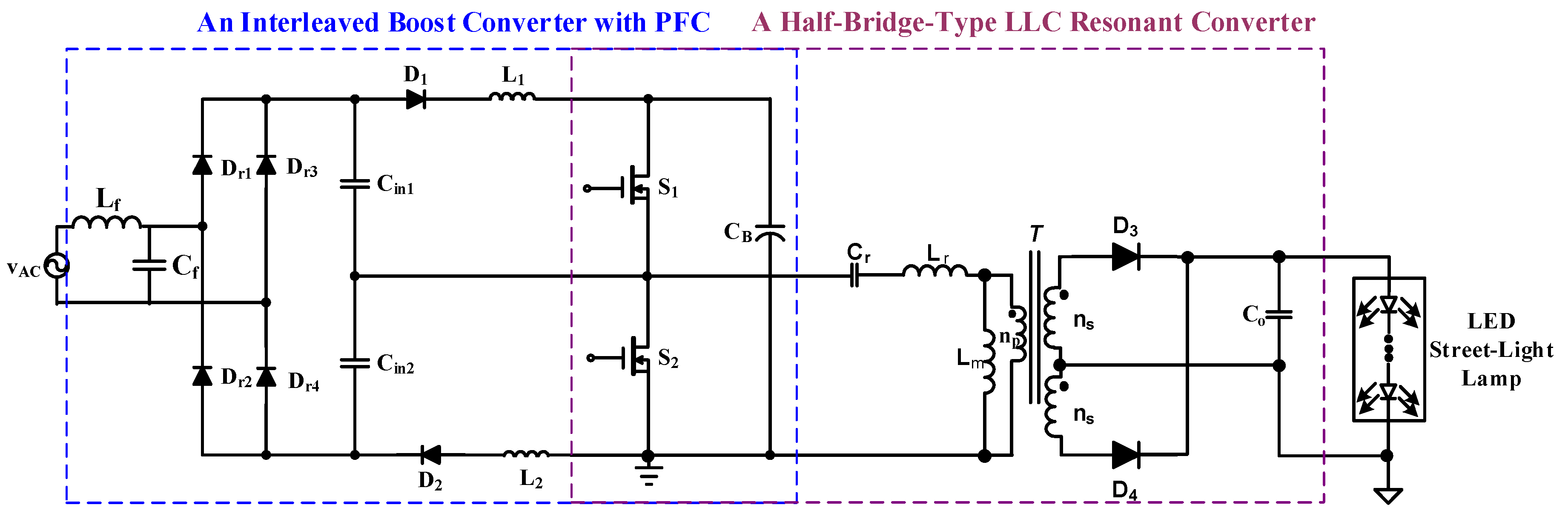
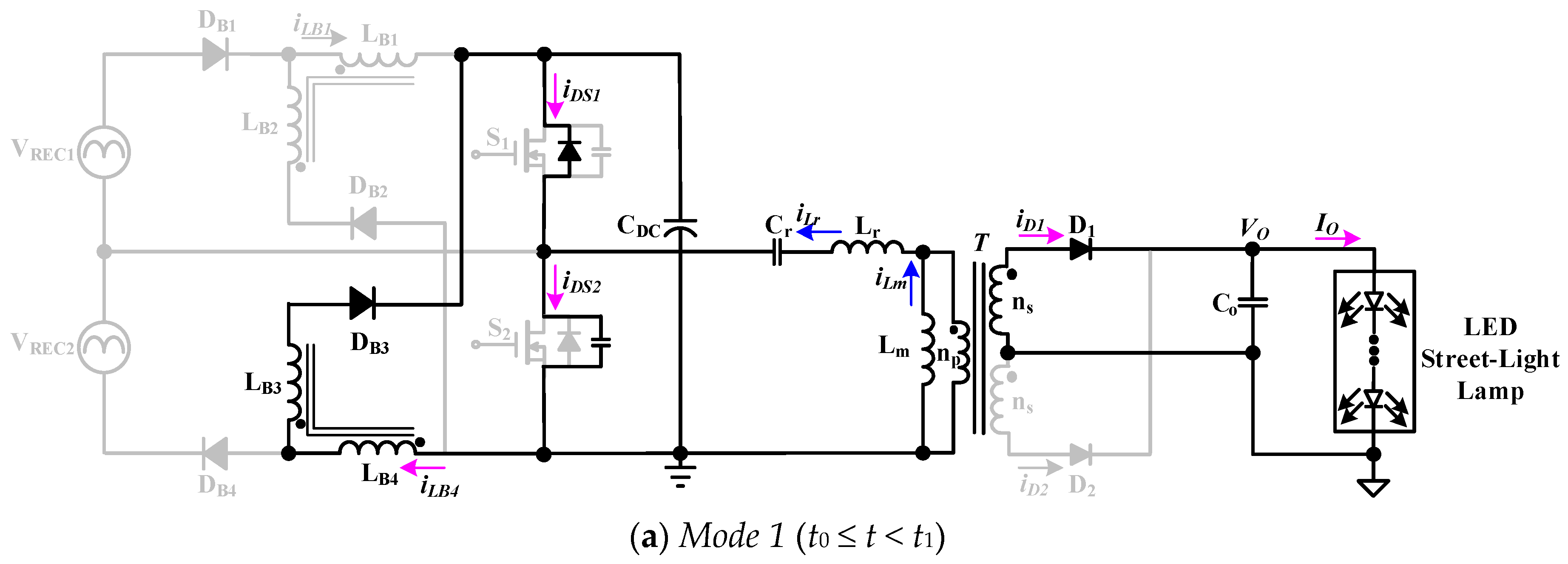
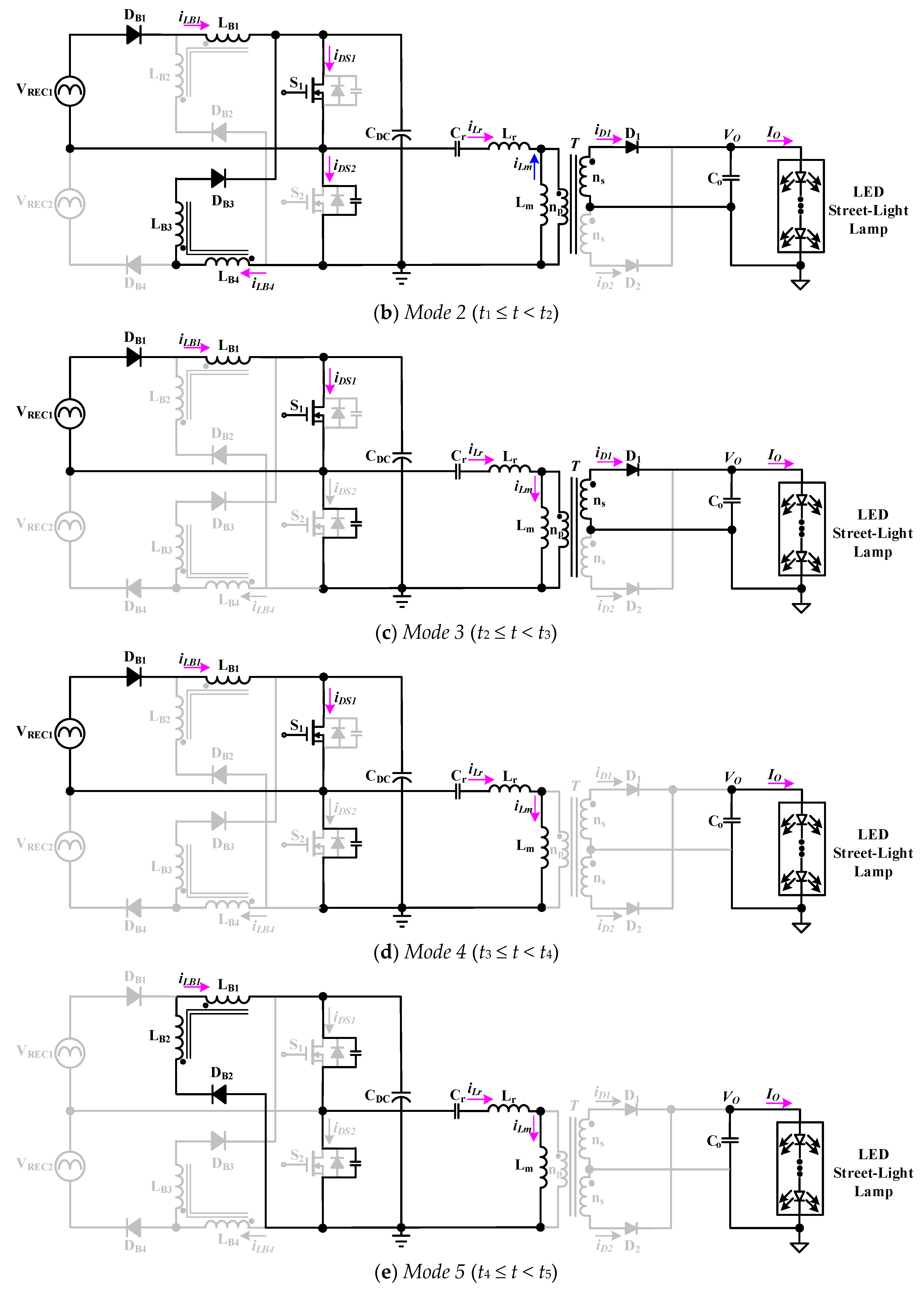
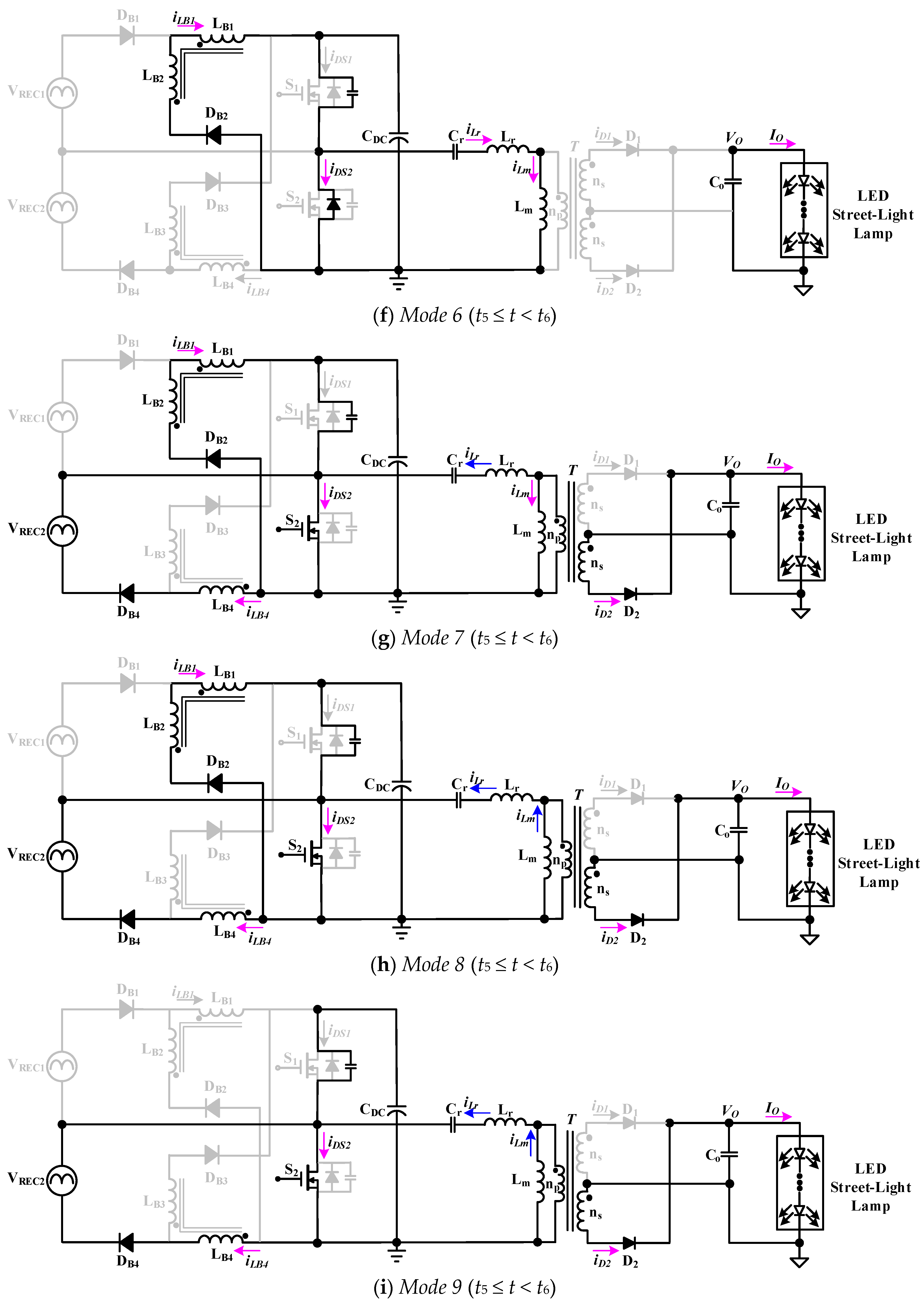
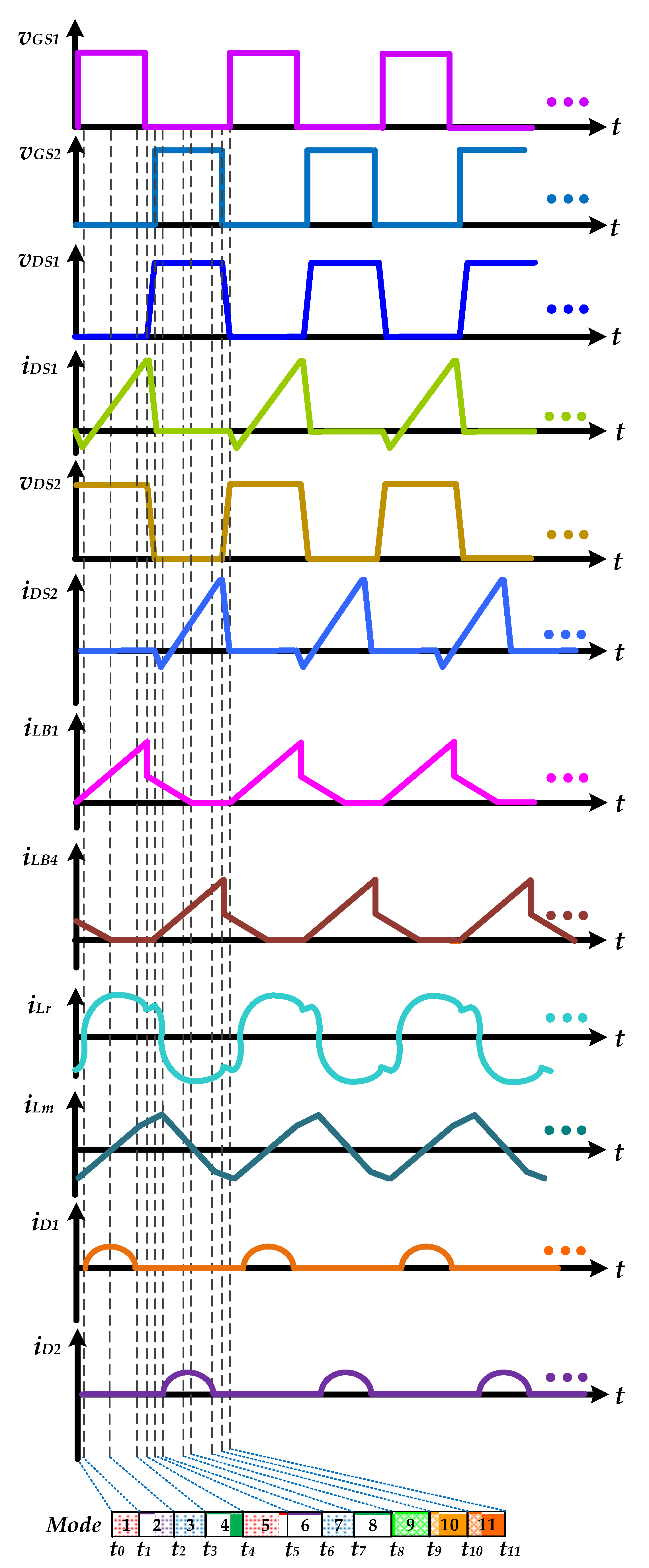
2. Description and Circuit Analysis of the Proposed Single-Stage Power Supply for Providing an LED Street-Light Lamp
- The input AC mains voltage can be regarded as a fixed level in each high-frequency switching cycle, because its switching frequency is much greater than that one of the utility line.
- The rectified equivalent voltage sources VREC1 and VREC2 are respectively expressed as the voltage on capacitors Cin1 and Cin2 after the AC mains voltage is passed through the inductor Lf, the capacitor Cf, and the full-bridge rectifier.
- The power switches S1 and S2 work complementarily, taking into account their essential diodes and parasitic capacitors.
- The forward-biased voltage drops and equivalent resistors of diodes (D1, D2, Do1, Do2, Do3, and Do4) are ignored.
- The equivalent series resistors of all capacitors are neglected.
- Two coupled inductors (LB1 and LB2; LB3 and LB4) are arranged to work in discontinuous conduction mode (DCM).
3. Design Considerations in the Presented Single-Stage AC-DC Power Supply for Providing an LED Street-Light Lamp
3.1. Design of the Coupled Inductors
3.2. Design of the LLC Resonant Network
4. Experimental Results of the Prototype AC-DC Power Supply for Providing an LED Street-Light Lamp
5. Bluetooth Wireless Dimming Tests of the Prototype AC-DC Power Supply for Providing an LED Street-Light Lamp
6. Conclusions
Author Contributions
Funding
Acknowledgments
Conflicts of Interest
References
- Brañas, C.; Azcondo, F.; Alonso, J.M. Solid-state lighting: A system review. IEEE Ind. Electron. Mag. 2013, 7, 6–14. [Google Scholar] [CrossRef]
- Almeida, P.S.; Camponogara, D.; Costa, M.A.D.; Braga, H.A.C.; Alonso, J.M. Matching LED and driver life spans: A review of different techniques. IEEE Ind. Electron. Mag. 2015, 9, 36–47. [Google Scholar] [CrossRef]
- Specifications of OSRAM HQL 250W E40. Available online: https://www.any-lamp.com/osram-hql-250w-e40 (accessed on 30 December 2020).
- Datasheet of LEDENVOTM LED Street Light. OSRAM. 2016. Available online: http://ls.osram.com.cn/pdf/EN_LEDENVO_Street_Light_Datasheet_v1p2_20160926.pdf (accessed on 30 December 2020).
- Wang, Y.; Guan, Y.; Xu, D.; Wang, W. A CLCL resonant DC/DC converter for two-stage LED driver system. IEEE Trans. Ind. Electron. 2016, 63, 2883–2891. [Google Scholar] [CrossRef]
- Arias, M.; Lamar, D.G.; Linera, F.F.; Balocco, D.; Diallo, A.A.; Sebastian, J. Design of a soft-switching asymmetrical half-bridge converter as second stage of an LED driver for street lighting application. IEEE Trans. Power Electron. 2012, 27, 1608–1621. [Google Scholar] [CrossRef]
- Wang, Y.; Guan, Y.; Liang, X.; Wang, W.; Xu, D. Two-stage LED street lighting system based on a novel single-stage AC/DC converter. IET Power Electron. 2014, 7, 1374–1383. [Google Scholar] [CrossRef]
- Naraharisetti, K.; Green, P.B. Design of 200 W Boost PFC Plus HB LLC Resonant Converter with IR1155, IRS27952 and IR11688. Application Note, Infineon. Available online: http://www.infineon.com (accessed on 30 December 2020).
- Camponogara, D.; Ferreira, G.F.; Campos, A.; Dalla Costa, M.A.; Garcia, J. Offline LED driver for street lighting with an optimized cascade structure. IEEE Trans. Ind. Appl. 2013, 49, 2437–2443. [Google Scholar] [CrossRef]
- Arias, M.; Lamar, D.G.; Sebastian, J.; Balocco, D.; Diallo, A. High-efficiency LED driver without electrolytic capacitor for street lighting. IEEE Trans. Ind. Appl. 2013, 49, 127–137. [Google Scholar] [CrossRef]
- Cheng, C.A.; Cheng, H.L.; Chung, T.Y. A novel single-stage high-power-factor LED street-lighting driver with coupled inductors. IEEE Trans. Ind. Appl. 2014, 50, 3037–3045. [Google Scholar] [CrossRef]
- Cheng, H.L.; Lin, C.W. Design and implementation of a high power-factor LED driver with zero-voltage switching-on characteristics. IEEE Trans. Power Electron. 2014, 29, 4949–4958. [Google Scholar] [CrossRef]
- Cheng, C.A.; Chang, C.H.; Chung, T.Y.; Yang, F.L. Design and implementation of a single-stage driver for supplying an LED street-lighting module with power factor corrections. IEEE Trans. Power Electron. 2015, 30, 956–966. [Google Scholar] [CrossRef]
- Wang, Y.; Guan, Y.; Ren, K.; Wang, W.; Xu, D. A single-stage LED driver based on DCM boost circuit and LLC converter for street lighting system. IEEE Trans. Ind. Electron. 2015, 62, 5446–5457. [Google Scholar] [CrossRef]
- Cheng, C.A.; Chung, T.Y. A single-stage LED streetlight driver with PFC and digital-PWM-dimming capability. Int. J. Circuit Theory Appl. 2016, 44, 1942–1958. [Google Scholar] [CrossRef]
- Luo, Q.; Huang, J.; He, Q.; Ma, K.; Zhou, L. Analysis and design of a single-stage isolated AC-DC LED driver with a voltage doubler rectifier. IEEE Trans. Ind. Electron. 2017, 64, 5807–5817. [Google Scholar] [CrossRef]
- Cheng, C.-A.; Chang, C.-H.; Cheng, H.-L.; Tseng, C.-H.; Chung, T.-Y. A single-stage high-power-factor light-emitting diode (LED) driver with coupled inductors for streetlight applications. Appl. Sci. 2017, 7, 167. [Google Scholar] [CrossRef]
- Cheng, C.A.; Cheng, H.L.; Chang, C.H.; Yang, F.L.; Chung, T.Y. A single-stage LED driver for street-lighting applications with interleaving PFC feature. In Proceedings of the IEEE International Symposium on Next-Generation Electronics, Kaohsiung, Taiwan, 25–26 February 2013; pp. 150–152. [Google Scholar]
- “Technical Application Guide—POWERTRONIC,” OSRAM. January 2013, pp. 1–42. Available online: http://www.osram.com/media/resource/hires/334206/technical-guide---powertronic-for-hid-lamps-gb.pdf (accessed on 30 December 2020).
- Bellido-Outeiriño, F.J.; Quiles-Latorre, F.J.; Moreno-Moreno, C.D.; Flores-Arias, J.M.; Moreno-García, I.; Ortiz-López, M. Streetlight control system based on wireless communication over DALI protocol. Sensors 2016, 16, 597. [Google Scholar] [CrossRef] [PubMed]
- Elejoste, P.; Angulo, I.; Perallos, A.; Chertudi, A.; Zuazola, I.J.G.; Moreno, A.; Azpilicueta, L.; Astrain, J.J.; Falcone, F.; Villadangos, J. An easy to deploy street light control system based on wireless communication and LED technology. Sensors 2013, 13, 6492–6523. [Google Scholar] [CrossRef] [PubMed]
- Cheng, C.A.; Cheng, H.L.; Chang, C.H.; Chang, E.C.; Hung, W.S.; Lan, L.F. A novel single-stage high-power-factor LED power supply with soft-switching feature for streetlight applications. In Proceedings of the IEEE International Symposium on Computer, Consumer and Control (IS3C2020), Taichung, Taiwan, 13–16 November 2020; pp. 1–3. [Google Scholar]
- Cheng, C.A.; Chang, C.H.; Cheng, H.L.; Chang, E.C.; Chung, T.Y.; Chang, M.T. A single-stage LED streetlight driver with soft-switching and interleaved PFC features. Electronics 2019, 8, 911. [Google Scholar] [CrossRef]


| Parameter | Value |
|---|---|
| Input utility-line voltage vAC | 110 V (rms) |
| Input utility-line frequency fAC | 60 Hz |
| Rated LED power | 144 W |
| Rated LED voltage | 36 V |
| Rated LED current | 4 A |
| Parameter | Value |
|---|---|
| Capacitors (Cin1, Cin2) | 330 nF |
| Coupled inductors (LB1 and LB2; LB3 and LB4) | 179 μH |
| Diodes (DB1, DB2, DB3, DB4) | MUR460 |
| Power switches (S1, S2) | STP20NM60 |
| DC-link capacitor CDC | 220 μF/450 V |
| Magnetizing inductor Lm | 450 μH |
| Resonant inductor Lr | 90 μH |
| Resonant capacitor Cr | 22 nF |
| Diodes (D1, D2) | MBR30H100CT |
| Output capacitor Co | 2200 μF/63 V |
| Parameter | Value |
|---|---|
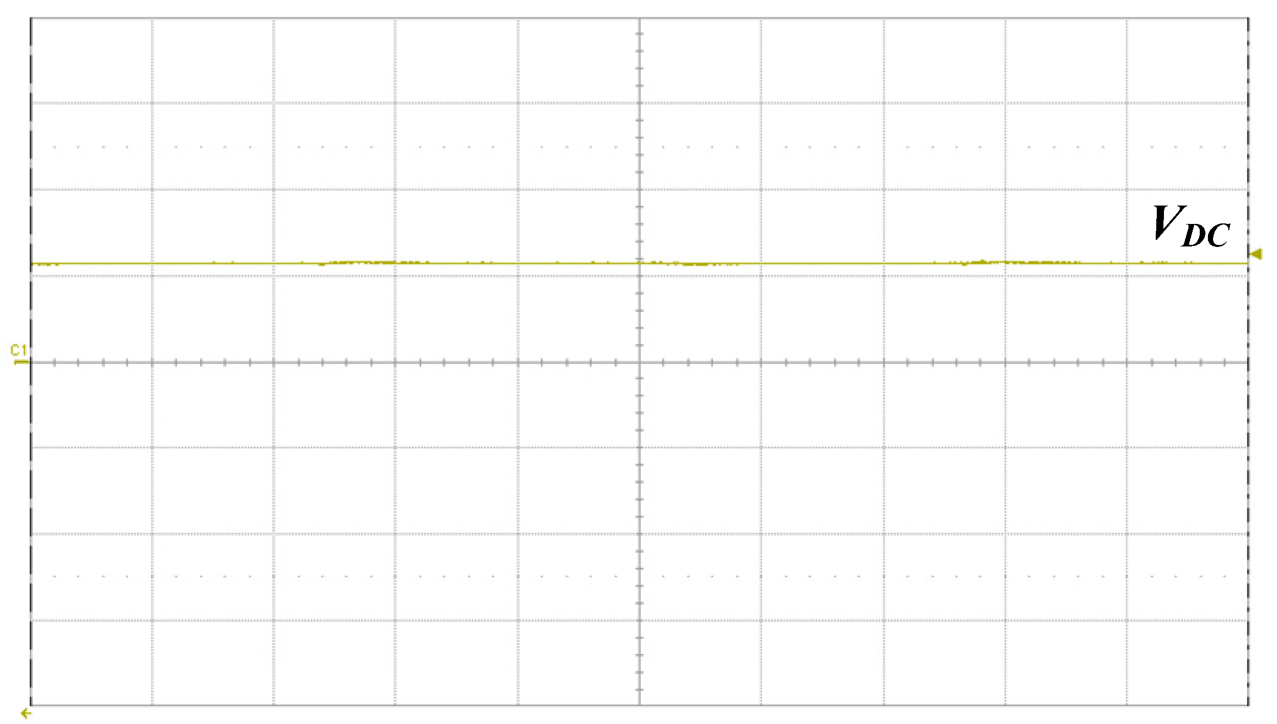
| Average level of output LED voltage | 36.03 V |
| Peak-to-peak level of output LED voltage | 1.3 V |
| Voltage ripple factor | 3.61% |
| Average level of output LED current | 3.938 A |
| Peak-to-peak level of output LED current | 67 mA |
| Current ripple factor | 1.7% |
| Item | Existing AC-DC LED Power Supply in Reference [18] | Presented AC-DC LED Power Supply |
|---|---|---|
| Circuit topology | Integration of interleaved boost converter and HB-LLCR converter | Integration of interleaved buck converter with coupled-inductors and HB-LLCR converter |
| Number of required power switches | 2 | 2 |
| Number of required diodes | 8 | 10 |
| Number of required capacitors | 6 | 6 |
| Number of required magnetic components | 5 | 5 |
| Input utility-line voltage | 110 V | 110 V |
| Output power | 144 W (36 V/4 A) | 144 W (36 V/4 A) |
| Measured power factor | >0.99 | >0.99 |
| Measured current THD | <10% | <3% |
| Measured circuit efficiency | >88% | >89.5% |
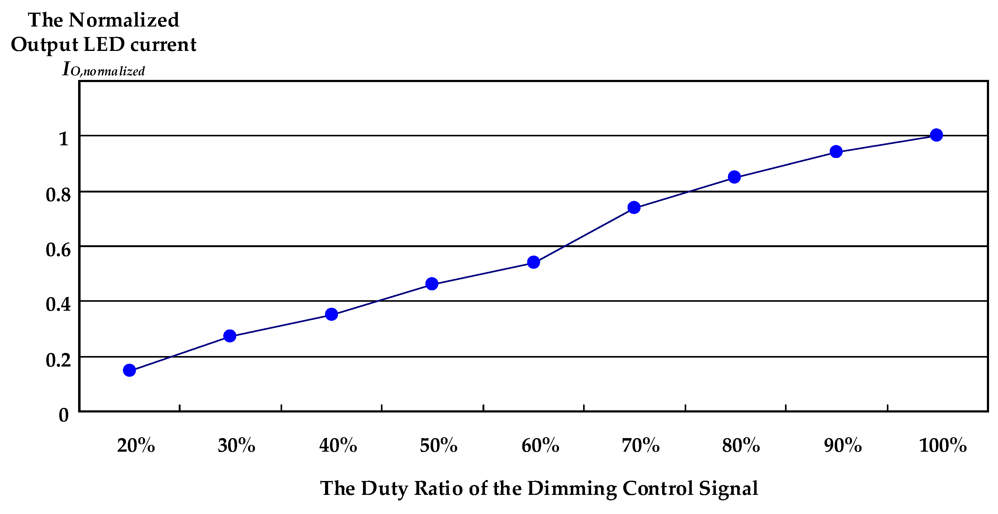
| Duty Ratio of the Dimming Control Signal | Measured Output LED Current IO |
|---|---|
| 20% | 0.591 A |
| 30% | 1.063 A |
| 40% | 1.378 A |
| 50% | 1.811 A |
| 60% | 2.127 A |
| 70% | 2.914 A |
| 80% | 3.347 A |
| 90% | 3.702 A |
| 100% | 3.938 A |
Publisher’s Note: MDPI stays neutral with regard to jurisdictional claims in published maps and institutional affiliations. |
© 2021 by the authors. Licensee MDPI, Basel, Switzerland. This article is an open access article distributed under the terms and conditions of the Creative Commons Attribution (CC BY) license (http://creativecommons.org/licenses/by/4.0/).
Share and Cite
Cheng, C.-A.; Cheng, H.-L.; Chang, C.-H.; Chang, E.-C.; Hung, W.-S.; Lai, C.-C.; Lan, L.-F. A Single-Stage High Power Factor Power Supply for Providing an LED Street-Light Lamp Featuring Soft-Switching and Bluetooth Wireless Dimming Capability. Energies 2021, 14, 477. https://doi.org/10.3390/en14020477
Cheng C-A, Cheng H-L, Chang C-H, Chang E-C, Hung W-S, Lai C-C, Lan L-F. A Single-Stage High Power Factor Power Supply for Providing an LED Street-Light Lamp Featuring Soft-Switching and Bluetooth Wireless Dimming Capability. Energies. 2021; 14(2):477. https://doi.org/10.3390/en14020477
Chicago/Turabian StyleCheng, Chun-An, Hung-Liang Cheng, Chien-Hsuan Chang, En-Chih Chang, Wei-Shiang Hung, Chin-Chih Lai, and Long-Fu Lan. 2021. "A Single-Stage High Power Factor Power Supply for Providing an LED Street-Light Lamp Featuring Soft-Switching and Bluetooth Wireless Dimming Capability" Energies 14, no. 2: 477. https://doi.org/10.3390/en14020477
APA StyleCheng, C.-A., Cheng, H.-L., Chang, C.-H., Chang, E.-C., Hung, W.-S., Lai, C.-C., & Lan, L.-F. (2021). A Single-Stage High Power Factor Power Supply for Providing an LED Street-Light Lamp Featuring Soft-Switching and Bluetooth Wireless Dimming Capability. Energies, 14(2), 477. https://doi.org/10.3390/en14020477