Article

Variable-Gain Super-Twisting Sliding Mode Damping Control of Series-Compensated DFIG-Based Wind Power System for SSCI Mitigation

School of Information Science and Electrical Engineering, Shandong Jiaotong University, Jinan 250357, China
*
Authors to whom correspondence should be addressed.
Energies 2021, 14(2), 382; https://doi.org/10.3390/en14020382
Submission received: 3 December 2020 / Revised: 4 January 2021 / Accepted: 8 January 2021 / Published: 12 January 2021

Abstract

:
Subsynchronous oscillation, caused by the interaction between the rotor side converter (RSC) control of the doubly fed induction generator (DFIG) and series-compensated transmission line, is an alleged subsynchronous control interaction (SSCI). SSCI can cause DFIGs to go offline and crowbar circuit breakdown, and then deteriorate power system stability. This paper proposes a novel adaptive super-twisting sliding mode SSCI mitigation method for series-compensated DFIG-based wind power systems. Rotor currents were constrained to track the reference values which are determined by maximum power point tracking (MPPT) and reactive power demand. Super-twisting control laws were designed to generate RSC control signals. True adaptive and non-overestimated control gains were conceived with the aid of barrier function, without need of upper bound of uncertainty derivatives. Stability proof of the studied closed-loop power system was demonstrated in detail with the help of the Lyapunov method. Time-domain simulation for 100 MW aggregated DFIG wind farm was executed on MATLAB/Simulink platform. Some comparative simulation results with conventional PI control, partial feedback linearization control, and first-order sliding mode were also obtained, which verify the validity, robustness, and superiority of the proposed control strategy.

1. Introduction

In order to cope with energy shortage and environmental pollution, countries all over the world are intensively promoting renewable energy development [1]. Wind energy is considered as one of the most promising types of renewable energy. In wind power generation systems, doubly fed induction generators (DFIG) play a leading role due to their distinct advantages [2]. However, DFIG-based wind farms are always far away from the load center and need long-distance transmission, which can weaken power capacity and stability margin [3]. Series-compensated capacitors are generally applied in the DFIG-based wind farms transmission line to enhance the capacity and stability [4].
Series-compensated capacitors method can induce subsynchronous control interaction (SSCI), due to the interaction between DFIG’s converter control and series-compensated transmission line [5,6]. In the SSCI, the frequency and attenuation rate are mainly codetermined by parameters of wind turbines and power transmission systems, irrelevant to natural modal frequency of shafting [7]. With no mechanical part involved, SSCI has a small damping effect, and also its divergence speed is faster than that of conventional subsynchronous resonance [8]. Thus, SSCI can cause more severe damage. From public reports, related accidents have been observed in America and China [5,9], causing equipment damage and loss of power generation.
In recent years, many efforts have been made on SSCI issues, e.g., frequency scan, eigenvalue analysis, complex torque coefficient method, and time domain simulation [10]. Based on these SSCI analysis methods, scholars tried to study SSCI damping strategies [11,12,13,14,15,16,17]. Papers [5,18,19,20,21] carried out many pioneering studies on modeling and supplementary damping control for subsynchronous resonance analysis. Paper [22] discussed multi-input multi-output supplementary damping control for both the rotor-side converter (RSC) and grid-side converter (GSC). In order to reduce the influence of PI control parameters on SSCI, paper [23] presented an optimization algorithm of PI parameters based on the t-distributed stochastic neighbor embedding for enhancing the damping. Paper [24] proposed a SSCI damping control for both the two control channels in the inner current loop of RSC with particle swarm optimized control coefficients. In short, the above studies [18,19,20,21,23,24] are all based on conventional double closed-loop PI control, and the design processes for SSCI damping controllers are relatively simple. Yet, these linear control methods can be inoperative when system operating points are changed, since a series-compensated DFIG-based wind power system is a complex and highly nonlinear system, with strong coupling features in both the aerodynamic and electrical parts [25,26]. These nonlinear factors can be dealt with by feedback linearization control. Paper [27] adopted a partial feedback linearization method to design damping controllers for GSC. Considering that RSC control is actually the dominant factor for SSCI mitigation, paper [28] continued the study of [27] to design SSCI damping controllers for RSC, achieving a good damping effect. Paper [29] proposed nonlinear controllers for both GSC and RSC based on the state feedback linearization method and verified its superior performance compared with conventional PI control.
Although feedback linearization control is an effective method for solving nonlinear problems in SSCI mitigation, it is rather sensitive to uncertainties in series-compensated DFIG-based wind power systems. These uncertainties exist in generator parameters, transmission line parameters, series compensation level, wind speed, and multiple series capacitor compensated lines, which can deteriorate subsynchronous oscillation of the system [30]. Hence, robustness is the desired characteristic for the series-compensated DFIG-based wind power control system. There are several attempts in SSCI robust control, such as H and active disturbance rejection methods [30,31,32].
The widely adopted sliding mode control [33,34], which possesses invariance property for system disturbances and parameter perturbation, is another good choice for robust control of SSCI. Papers [35,36] discussed SSCI mitigation strategies by combining feedback linearization control with sliding mode method. Paper [9] proposed first-order sliding mode controllers to track the reference rotor currents for damping SSCI. Control chattering of rotor voltage, which can damage electronic components and increase SSCI, is a big obstacle for these conventional sliding mode methods. Furthermore, the upper bounds of system uncertainties derivatives, which are actually hard to calculate beforehand, have to be known in advance for all the above robust control methods.
Consequently, this paper proposes a novel variable-gain super-twisting damping control strategy for SSCI mitigation. It can greatly reduce sliding mode chattering and does not need the unknown upper bounds of uncertainty derivatives. The SSCI mechanism was firstly analyzed with the aid of the presented series-compensated DFIG-based wind farm model. Rotor current dynamics constraint was identified as the dominant factor for SSCI mitigation. Super-twisting control laws were then constructed to track the prescribed rotor currents under dq direction. Adaptive control laws were subsequently conceived via barrier function. Then, the control gains can be self-adjusted following the upper bounds of uncertainty derivatives. SSCI mitigation was achieved without conservative RSC control signals. The performance of the newly designed variable-gain super-twisting sliding mode (VGSTSM) damping control scheme was evaluated under different wind speed, series compensation level, and short circuit fault. Comparative studies with conventional PI method, feedback linearization control, and first-order sliding mode control were also completed to verify the superiority.
This paper is organized as follows. Modeling for series-compensated DFIG-based wind farm is stated in Section 2. Section 3 details SSCI mechanism, design procedure of the proposed control strategy, and stability proof of the closed-loop power system. The demonstration of effectiveness and superiority of the proposed VGSTSM damping control strategy for SSCI mitigation is shown in Section 4. Some conclusions are finally drawn in Section 5.

2. Series-Compensated DFIG-Based Wind Power System Modeling

The model of a series-compensated DFIG-based wind farm is shown in Figure 1 [18,36]. It mainly includes wind turbine, shafting, induction generator, RSC, DC bus link, GSC, and series-compensated transmission line. DFIG represents the 100 MW equivalent lumped model of 50 generators (2 MW for each unit). R s and L s are stator resistance and inductance, respectively. R R S C and L R S C are RSC link resistance and inductance, respectively. R G S C and L G S C are GSC link resistance and inductance, respectively. R L and L L are equivalent resistance and inductance of series-compensated transmission line, respectively. C d c is DC bus capacitor, and C S C is the series-compensated capacitor. e is the grid voltage. System equations are all analyzed under the synchronous rotating reference frame.
Power fluctuation and subsynchronous rotor current will be induced when subsynchronous disturbance current occurs in the series-compensated transmission line. The affected RSC generates corresponding output voltage, and then injects subsynchronous current into the rotor, and finally induces the superposition of the stator side and the original disturbance. It will increase the original disturbance and form a divergent subsynchronous oscillation if the amplitude of the superimposed current is larger than that of the original disturbance current.
Electrical dynamic of series-compensated DFIG-based wind farms can be deduced via Kirchhoff’s laws under a synchronous rotating reference frame.
d i r d d t = ω 1 i r q - R r L r i r d u r d L r + u d c L r S d d i r q d t = ω 1 i r d - R r L r i r q u r q L r + u d c L r S q d u d c d t = 1 C d c i d c 1 C d c i r d S d 1 C d c i r q S q d i s d d t = ω 1 i s q + R s L s i s d + u s d L s d i s q d t = ω 1 i s d + R s L s i s q + u s q L s d i g d d t = ω 1 i g q R G S C L G S C i g d u g d L G S C d i g q d t = ω 1 i g d R G S C L G S C i g q u g q L G S C d i L d d t = ω 1 i L q + R L L L i L d + 1 L L u l d u s c d E d d i L q d t = ω 1 i L d + R L L L i L q + 1 L L u l q u s c q E q d u s c d d t = ω 1 u s c q + 1 C S C i L d d u s c q d t = ω 1 u s c d + 1 C S C i L q
where u g , i g , u s , i s , u r , i r , u d c , and i d c are the voltages and currents of GRC, stator, rotor, and DC bus capacitor, respectively. u S C is defined as series-compensated voltage. R r = R r + R R S C , R s = R s + R L , L s = L s + L L 1 / ω 1 2 C S C , and L r = L r + L R S C L m 2 / L s .
After the applied stator field-orient, the stator active and reactive power for the DFIG model described in the dq reference frame can be represented as:
P s = 3 L m 2 L s U s i r q Q s = 3 U s 2 L s ω 1 U s ω 1 L m i r d
According to Betz theory, mechanical power captured by wind turbine is denoted as:
P T = 1 2 C p S w ρ T υ T 3
where C p is power coefficient, S w is the blade sweep area, ρ T is air density, and υ T is wind speed. As is shown in Equation (3), the mechanical power, P T , is determined by power coefficient, C p , under the fixed wind speed. C p is related to tip speed ratio, λ T , and blade pitch angle, β T , with the typical functional relation [27,36]:
C p = 0.5176 116 λ i 0.4 β T 5 21 λ i + 0.0068 λ T
Two related equations are 1 λ i = 1 λ T + 0.08 β T 0.035 β T 3 + 1 and λ T = ω T R T υ T , where ω T is mechanical angular speed and R T is the rotor radius of the wind turbine. With the change of λ T and fixed β T , power coefficient, C p , has a maximum value, C p max , and the corresponding λ T is optimum tip speed ratio, λ T o p t . In other words, for a specific wind speed, the wind turbine can only run under specific mechanical angular speed, ω T , to achieve maximum power point tracking (MPPT). Thus, generator rotor speed must be regulated timely with the change of wind speed to capture maximum power.
The mechanical drive system of the wind turbine transmits the captured kinetic energy to the generator via the gear box, high speed shaft, and low speed shaft. It is rather complicated, and the mechanical shaft dynamic can be modeled as one mass, two mass, and three mass, according to different modeling methods [18]. The two mass model is sufficient and widely praised in SSCI studies, and its dynamic is represented as:
d ω T d t = 1 2 H T T T K s θ s d ω r d t = 1 2 H G K s θ s T e d θ s d t = 2 π f 1 ω T ω r N g
where H T and H G are inertia time constants of wind turbine and generator, respectively; K s is stiffness coefficient of shafting; θ s is relative angular displacement of the two mass block; T T and T e denote mechanical torque and electromagnetic torque of the wind turbine and generator, respectively; ω r is rotor angular speed of the generator; N g represents gear ratio; and f 1 is power frequency.

3. SSCI Analysis and Control Design

3.1. SSCI Mechanism

For conventional double closed-loop PI control of RSC under stator-flux oriented method, the increments of rotor voltage and current under dq reference frame are [22,28]:
Δ u r d = R r Δ i r d k 1 ω s ω r Δ i r q + k 1 p Δ i r d Δ u r q = R r Δ i r q k 1 ω s ω r Δ i r d + k 1 p Δ i r q Δ i r d = 1 k 2 Δ i s d Δ i r q = 1 k 2 Δ i s q
where k 1 = L r L m 2 / L s and k 2 = L m / L s , and p is the differential operator.
The terminal voltage of DFIG is supposed to be a three-phase symmetric fundamental sinusoidal wave, and phase voltage is expressed as:
u s a = 2 U s sin ( ω s t + φ u 0 )
where φ u 0 is initial phase of fundamental voltage.
When current disturbance (with resonance angular frequency, ω n ) appears in the fixed series-compensated transmission line, a phase current of DFIG can be expressed as:
i s a = 2 I s sin ( ω s t + φ i 0 ) + 2 I n sin ( ω n t + φ i n ) = i s a 0 + i s a _ s u b
where I s and φ i 0 are effective value and initial phase of fundamental current, i s a 0 , respectively. I n , ω n , and φ i n are effective value, angular frequency, and initial phase of subsynchronous current, i s a _ s u b , respectively.
Under dq reference frame, subsynchronous voltage and current can be expressed as:
u s d = 0 u s q = 3 U s
i s d = 3 I s sin ( φ u 0 φ i 0 ) 3 I n sin ( ω s ω n ) t + φ i = i s d 0 + i s d _ s u b i s q = 3 I s cos ( φ u 0 φ i 0 ) 3 I n cos ( ω s ω n ) t + φ i = i s q 0 + i s q _ s u b
where φ i = φ u 0 φ i n , i s d 0 , and i s q 0 are direct current components of stator current under dq frame, and i s d _ s u b and i s q _ s u b are subsynchronous components with frequency ω s ω n .
It is supposed that fundamental power can be accurately tracked, and variation of instantaneous active and reactive power only contains subsynchronous components.
Δ p s = 3 U s I n cos ( ω s ω n ) t + φ i = 3 U s i s q _ s u b Δ q s = 3 U s I n sin ( ω s ω n ) t + φ i = 3 U s i s d _ s u b
As is shown in Formula (11), subsynchronous current with angular frequency, ω n , can induce power fluctuation with angular frequency, ω s ω n . Then, Δ p s and Δ q s can enter into the inner current control loop and turn into reference values of the rotor current. Meanwhile, a rotating magnetic field is formed via cutting rotor winding by subsynchronous current of the stator side, then three phase subsynchronous current with angular frequency, ω r ω n , is induced in rotor winding, which can cause rotor voltage disturbances. These disturbances react upon rotor winding and impose subsynchronous current with angular frequency, ω s ω n ,which eventually cause a new subsynchronous current. Once this new subsynchronous current is added to original current disturbance, 2 I n sin ( ω n t + φ i n ) , the current disturbance will be gradually increased. The DFIG controller and series-compensated transmission line interacts and stimulates each other, which causes diverging oscillation of active and reactive power.

3.2. Control Design

As analyzed above, SSCI can be well suppressed once the rotor current dynamic is constrained by following the prescribed values. The reference values of rotor current can be deduced from (2), where active power, P s , is acquired by maximum power point tracking (MPPT) and reactive power, Q s , is calculated according to grid demand.
i r q = 2 L s P s 3 L m U s i r d = U s ω 1 L m 2 L s Q s 3 L m U s
SSCI is mainly caused by the interaction between the RSC control and series-compensated transmission line. Thus, RSC control signals are chosen as control variables. According to (3) and (4), the equation of series-compensated wind power systems can be represented as:
x ˙ = f ( x ) + g ( x ) u y = h ( x )
f ( x ) = ω 1 i r q - R r L r i r d ω 1 i r d - R r L r i r q 1 C i d c ω 1 i s q + R s L s i s d + u s d L s ω 1 i s d + R s L s i s q + u s q L s ω 1 i g q R G S C L G S C i g d u g d L G S C ω 1 i g d R G S C L G S C i g q u g q L G S C ω 1 i L q + R L L L i L d + 1 L L u l d u s c d E d ω 1 i L d + R L L L i L q + 1 L L u l q u s c q E q ω 1 u s c q + 1 C S C i L d ω 1 u s c d + 1 C S C i L q 1 2 H T T T K s θ s 1 2 H G K s θ s T e 2 π f 1 ω T ω r N g
g ( x ) = u d c 2 L r 0 0 u d c 2 L r 1 C d c i r d 1 C d c i r q 0 0 0 0 0 0 0 0 0 0 0 0 0 0 0 0 0 0 0 0 0 0
where state vector is x = [ i r d   i r q   u d c   i s d   i s q   i g d   i g q   i L d   i L q   u s c d   u s c q   ω T   ω r   θ s ] T , control variables are u = [ S r d   S r q ] T , and output equations are y = [ i r d i r d *   i r q i r q * ] T .
To choose sliding mode function:
σ r d = i r d i r d * + c 1 i r d i r d * d t
σ r q = i r q i r q * + c 2 i r q i r q * d t
where positive constants, c 1 and c 2 , are weight coefficients of integral sliding mode items. This can help to remove steady state error. To calculate first-order derivatives of σ r d and σ r q :
σ ˙ r d = ω 1 i r q R r L r i r d i ˙ r d * + c 1 i r d i r d * + u d c 2 L r S r d
σ ˙ r q = ω 1 i r d R r L r i r q i ˙ r q * + c 2 i r q i r q * + u d c 2 L r S r q
Observed from (18) and (19), the relative degrees with respect to σ r d and σ r q are both 1. They are less than the system order, which is 14. System dynamics can be divided into external dynamics and internal dynamics, according to zero dynamics stability theory. External dynamics are normally demanded to be stable and have good dynamic quality, while internal dynamics can only satisfy asymptotic stability. This paper will not go into details about asymptotic stability of internal dynamics for series-compensated DFIG wind power systems, which has been stated in papers [28,29]. Next, the design procedure for VGSTSM control law will be presented in detail. Here, i r q control design is taken as an example because the design procedure is similar for i r d .
Considering parameter perturbation, measuring error, and external disturbance, the lumped uncertainty is represented by Δ d q . Then, formula (19) was rewritten as:
σ ˙ r q = ω 1 i r d R r L r i r q i ˙ r q * + c 2 i r q i r q * + u d c 2 L r S r q + Δ d q
Taking state feedback control into account, this gave:
S r q = 2 L r u d c ω 1 i r d + R r L r i r q + i ˙ r q * - c 2 i r q i r q * + v r q
Then:
σ ˙ r q = v r q + Δ d q
The next step was to design auxiliary control law, v r q , for (22). RSC control chattering can be rather serious if conventional first-order sliding mode method is adopted. Thus, super-twisting algorithm with continuous control effect and small chattering was employed to construct v r q :
v r q = - α q γ q σ r q 1 / 2 s i g n ( σ r q ) + v r q 2 v ˙ r q 2 = β q γ q 2 s i g n ( σ r q )
The upper bound D q u p of Δ d ˙ q was demanded to be known in this control law. If control parameters, α q and β q , were chosen as 1.5 and 1.1, and γ q was set as D q u p , then finite time stability and second-order sliding mode with respect to σ r q can be established [37]. However, this upper bound D q u p is hard to acquire in series-compensated DFIG-based wind power systems. In case the value for D q u p is conservative, RSC will produce excessive control effect, increase unnecessary chattering, and damage electromechanical devices. Therefore, the super-twisting control gains should be constructed as adaptive ones. Control gains can increase or decrease according to upper bound of uncertainty derivatives. This adaptive strategy does not only satisfy control requirement, but also restrains chattering, and the superiority of super-twisting algorithm is fully developed.
Considering the characteristic of barrier function [37], adaptive gain super-twisting sliding mode control law is designed as:
v r q = 1.5 γ q σ r q 1 / 2 s i g n ( σ r q ) + v r q 2 v ˙ r q 2 = 1.1 γ q s i g n ( σ r q )
Adaptive control gain is constructed as:
γ ˙ q = γ q 0 , i f   0 < t t r s γ q = b q ε q ε q | σ r q | , i f   t r s < t
where t r s is the time that | σ r q | reaches ε q / 2 . γ q 0 and b q , ε q are positive constants. Then, for any ε q > 0 , t r s > 0 for any initial status, σ r q ( 0 ) . When t t r s , then | σ r q | < ε q is satisfied. It was indicated that i r q can converge to the error range of its reference value in finite time and achieve actual tracking for i r q * .
The proof for the above conclusion is followed below. Firstly, let us prove that | σ r q | can reach ε q / 2 in finite time, t r s . It is supposed that | σ r q ( 0 ) | > ε q 2 is satisfied, then adaptive control gain is determined by γ ˙ q = γ q 0 , according to (25).
Consider the following variable transformation:
z q 1 = σ q γ q 2 z q 2 = σ ˙ q γ q 2
The derivatives for z q 1 and z q 2 can be denoted as:
z ˙ q 1 = α q | z q 1 | 1 / 2 s i g n ( z q 1 ) + z q 2 2 γ ˙ q γ q z q 1 z ˙ q 2 = β q s i g n ( z q 1 ) Δ d ˙ q γ q 2 2 γ ˙ q γ q z q 2
Choose Lyapunov function:
V q 1 = χ q T ( t ) P q χ q ( t )
where P q is constant symmetric positive definite matrix, χ q T ( t ) = | z q 1 | 1 / 2 s i g n ( z q 1 ) z q 2 . Then, time derivative of χ q ( t ) can be deduced as:
χ ˙ q ( t ) = 1 2 | z q 1 | 1 / 2 Κ q χ q + γ ˙ q γ q Λ q χ q Μ q γ q 2
where Κ q = α q / 2 1 / 2 β q 0 , Λ q = 1 / 2 0 0 1 , and Μ q = 0 Δ d ˙ q .
Time derivative of V q 1 is:
V ˙ q 1 = 1 2 | z q 1 | 1 / 2 χ q T Q q χ q γ ˙ q γ q χ q T R q χ q 2 Δ d ˙ q γ q 2 P q χ q
where K q T P q + P q K p = Q p and Λ q T P q + P q Λ q = R q . Then, thanks to the studies in [12], symmetric positive definite matrix, P q , exits, and then Q p are R q are positive definite. Then:
V ˙ q 1 k q 1 V q 1 1 2 + 2 k q 3 D q u p γ q 2 V q 1 1 2 γ ˙ q γ q k q 2 V q 1
where k q 1 = λ min ( Q q ) 2 p 11 λ max ( P q ) , k q 2 = λ min ( R q ) λ max ( P q ) , and k q 3 = λ max ( R q ) λ min ( P q ) 1 2 . λ min and λ max are minimum eigenvalue and maximum eigenvalue of the relative matrix, respectively. p 11 is the first element of matrix P q .
The first item of the right side in (31) is negative, while the second item is positive. Here, the second item will decrease following increasement of adaptive control gain. Adaptive control gain becomes big enough to conquer uncertainties. Thus, the second item becomes very small. The third item will be negative and further reduced when γ ˙ q is negative.
As discussed, the first item will be bigger than the second one, and the third item will become smaller. Then, the right side of (31) will be negative and V ˙ q 1 a q V q 1 1 / 2 satisfied, which means finite time stability is achieved. V q 1 will continue to decrease and then | σ r q | can reach ε q / 2 .
It was proved above that | σ r q | can reach ε q / 2 when the time is t = t r s . The second step is to prove that | σ r q | ε q can be satisfied after t t r s .
Choose Lyapunov function:
V q 2 = 1 2 σ r q 2
Then:
V ˙ q 2 = σ r q σ ˙ r q = σ r q - α q γ q σ r q 1 / 2 s i g n ( σ r q ) + σ r q 2
where σ r q 2 = v r q 2 + Δ d q . Then:
V ˙ q 2 | σ r q | - α q γ q σ r q 1 / 2 s i g n ( σ r q ) + | σ r q 2 |
According to the barrier function, γ q = b q ε q ε q | σ r q | , of (25):
V ˙ q 2 | σ r q | ε q | σ r q | α q ε q b q σ r q 1 / 2 | σ r q 2 | ε q + σ r q σ r q 2 = σ r q σ r q 2 ε q | σ r q | α q ε q b q σ r q 1 / 2 σ r q 2 ε q + σ r q
Take note of the right side of (35), define:
F q = α q ε q b q σ r q 1 / 2 σ r q 2 ε q + σ r q
F q = 0 is a quadratic equation, and the two roots are:
e 11 1 / 2 = 1 2 α q ε q b q σ r q 2 + α q ε q b q σ r q 2 2 + 4 ε q 1 / 2
e 12 1 / 2 = 1 2 α q ε q b q σ r q 2 α q ε q b q σ r q 2 2 + 4 ε q 1 / 2
It can be easily observed that the second root is negative, and then only the second root needed to be paid more attention. According to (37):
e 11 = ± 1 4 α q ε q b q σ r q 2 + α q ε q b q σ r q 2 2 + 4 ε q 1 / 2 2
According to the well-known inequation, a 2 + b 2 a + b 2 :
α q ε q b q σ r q 2 2 + 2 ε q 1 / 2 2 α q ε q b q σ r q 2 + 2 ε q 1 / 2 2
With the aid of (40), the upper bound of e 11 can be written as:
e 11 α q ε q b q σ r q 2 + α q ε q b q σ r q 2 + 2 ε q 1 / 2 2 1 2 2 2 = α q ε q b q σ r q 2 + α q ε q b q σ r q 2 + 2 ε q 1 / 2 2 2 = 2 ε q 1 / 2 2 2 = ε q
Finally, the inequation from (41) can be deduced as:
e 11 2 ε q 1 / 2 2 2 ε q
If σ q ( t ) e 11 , then F q is positive definite. Consequently, V ˙ q 2 < 0 is satisfied for e 11 σ q ( t ) < ε q . Hence, σ q ( t ) will always satisfy σ q ( t ) < e 11 the rest of the time, and e 11 is smaller than ε q for any derivative of Δ d q .
Therefore, real sliding mode, with respect to σ q ( t ) , is established in finite time. The q-axis rotor current, i r q , allows us to track for the prescribed i r q * with unknown upper bound of uncertainty derivative.
Adaptive gain control law for σ r d can be designed in a similar way. State feedback control is:
S r d = 2 L r u d c ω 1 i r q + R r L r i r d + i ˙ r d * - c 1 i r d i r d * + v r d
Sliding mode control law and adaptive control gain are:
v r d = 1.5 γ d σ r d 1 / 2 s i g n ( σ r d ) + v r d 2 v ˙ r d 2 = 1.1 γ d s i g n ( σ r d )
γ ˙ d = γ d 0 , i f   0 < t t r s 1   γ d = b d ε d ε d | σ r d | , i f   t r s 1 < t
i r d can converge to the demanded neighborhood in finite time. As mentioned above, the internal dynamics of the system are asymptotically stable, and the external dynamics are finite time stable. Thus, the stability of the whole control system is guaranteed.

4. Time-Domain Simulation

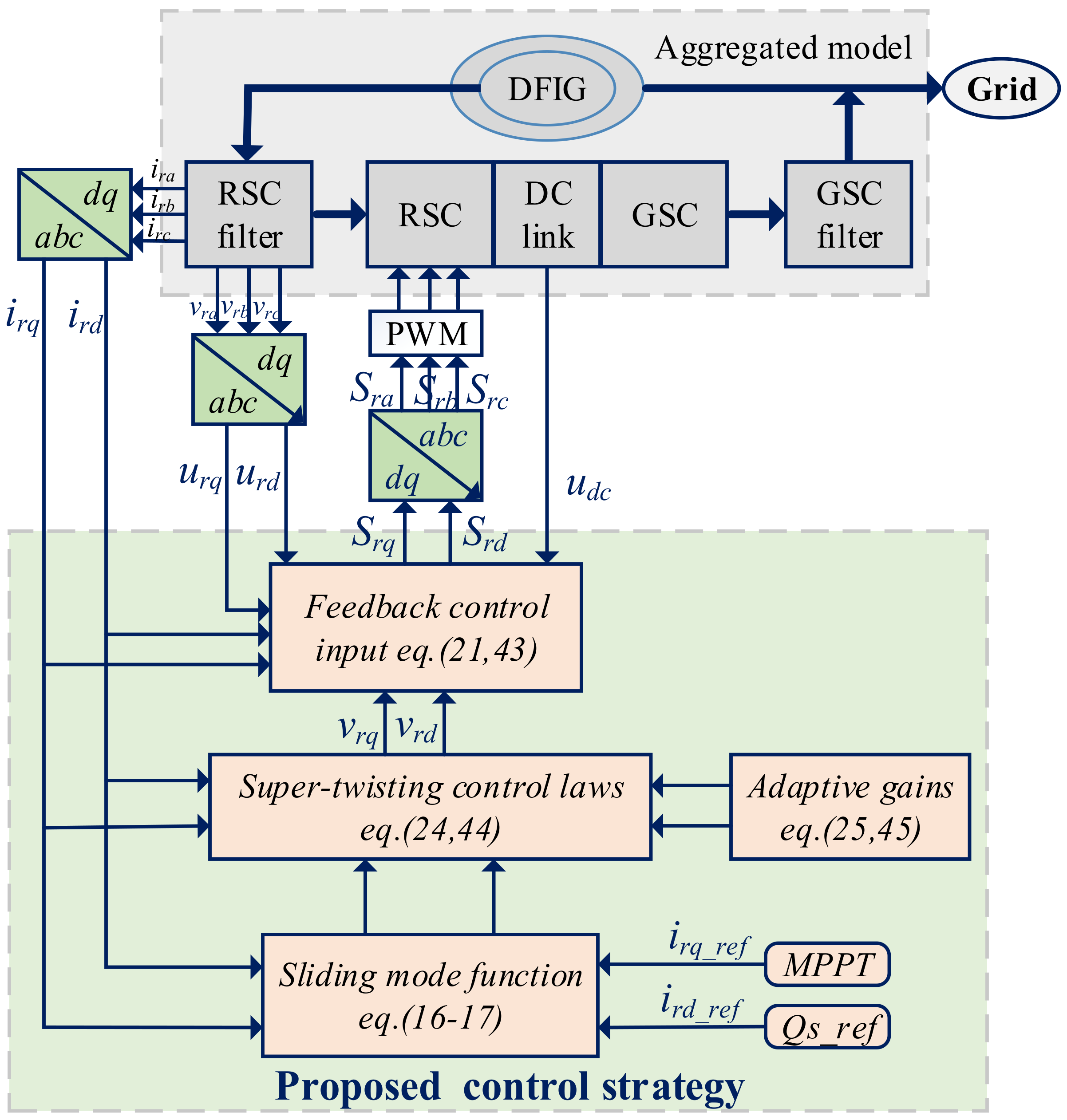
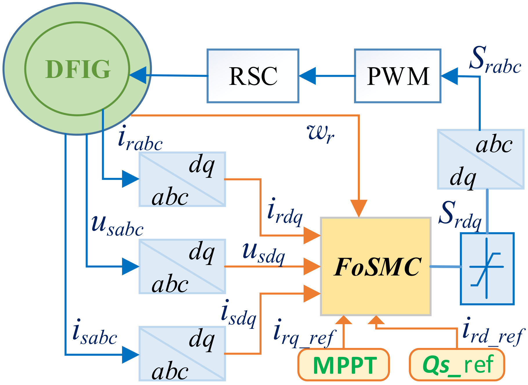
Time-domain simulation is one of the best measures for dynamic stability analysis of a power system. Nonlinear mathematical models can be employed in time-domain simulations, which is very suitable for the nonlinear and complex characteristics of the DFIG power system. The 100 MW aggregated model was adopted to verify effectiveness. Superiority of the proposed control strategy was also compared with PI [19], feedback linearization [27], and conventional sliding mode methods [9] under MATLAB/Simulink. Simulation parameters for series-compensated DFIG-based wind power systems is referred to Table 1. The schematic diagram of the proposed VGSTSM damping control scheme is depicted as Figure 2. Firstly, the sliding mode functions were calculated, then the auxiliary control quantities were obtained according to the adaptive law and super-twisting sliding mode control laws, and finally the RSC control signals were obtained through the feedback control. Control parameters were chosen as ε q = 0.001 , γ q = 2.2 , b q = 2.0 , ε d = 0.001 , γ d = 2.5 , and b d = 2.3 .
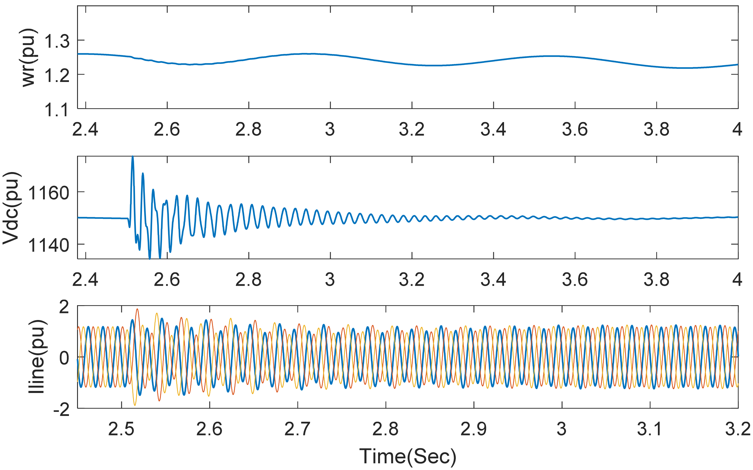
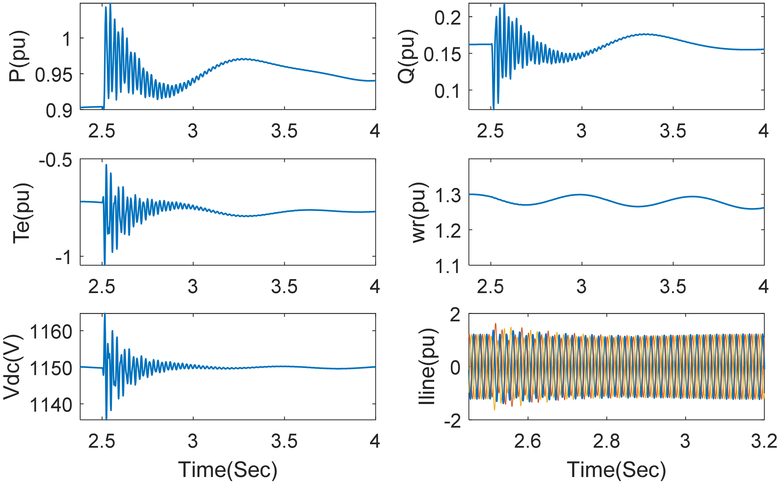
The wind speed was set as 9 m/s. Series-compensated capacitator was injected into the DFIG-based wind power transmission line at 2.5 s, forming 40% series-compensated level. Transient responses of active power, reactive power, electromagnetic torque, rotor angular speed, DC bus voltage, and transmission line current are shown in Figure 3 and Figure 4. As observed, all of these variables start oscillation when this switch capacitator is put into the system, they can then be rapidly stabilized under the proposed control strategy. When the series-compensated level is increased to 85%, the variables can still converge to steady state, as shown in Figure 5 and Figure 6, though the oscillation time somewhat increased. Figure 3, Figure 4, Figure 5 and Figure 6 indicate that the proposed strategy was effective for SSCI mitigation under different series-compensated level.
Wind speed increased to 11 m/s under 85% compensation to evaluate controller performances for different wind speeds. The responses of these variables are demonstrated in Figure 7. By comparing Figure 7 with Figure 5 and Figure 6, it was observed that SSCI mitigation was better when wind speed was higher.
After the system entered steady state, three-phase short circuit fault occurred at the high voltage side of transformer at t = 5 s to verify capacity for fault ride-through of the proposed control method. The duration of the fault was 20 ms. As shown in Figure 8, dynamic responses of active power, reactive power, and electromagnetic torque can all return to normal after a short transient fluctuation. This indicates that SSCI can be quickly suppressed under three-phase short circuit fault and the capacity for fault ride-through was enhanced under the proposed control method.
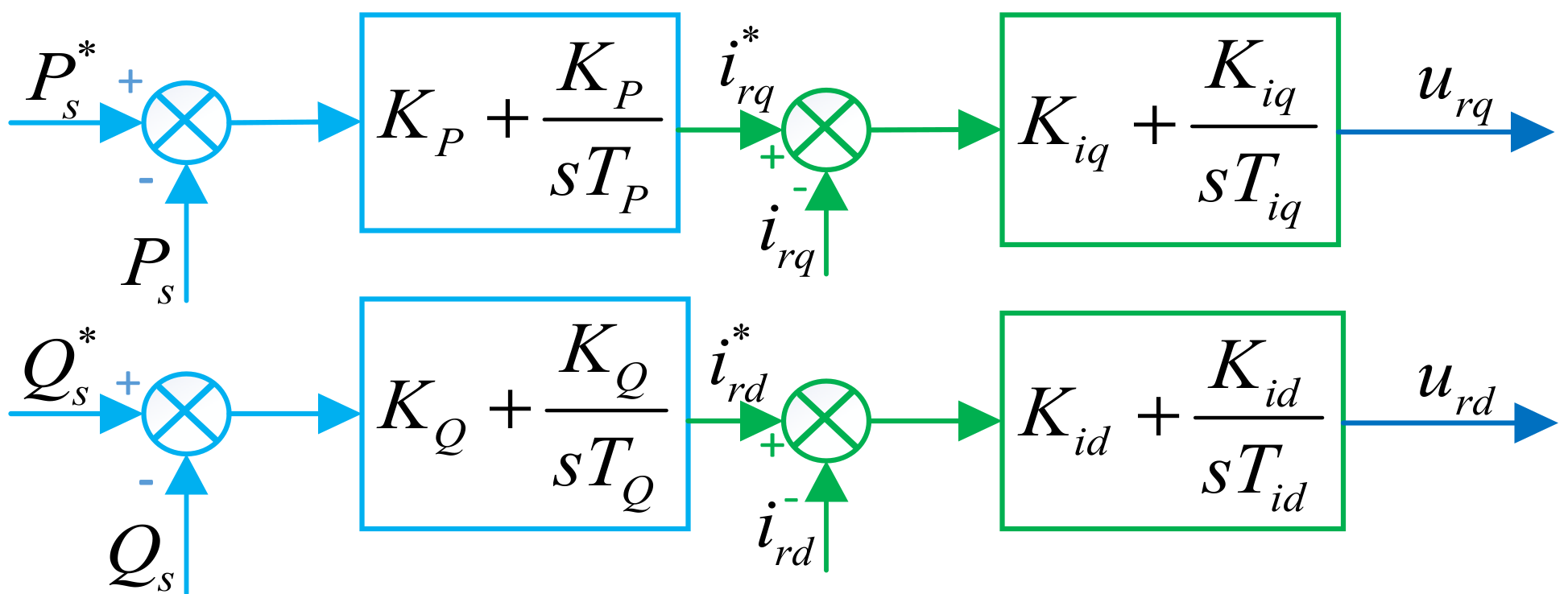
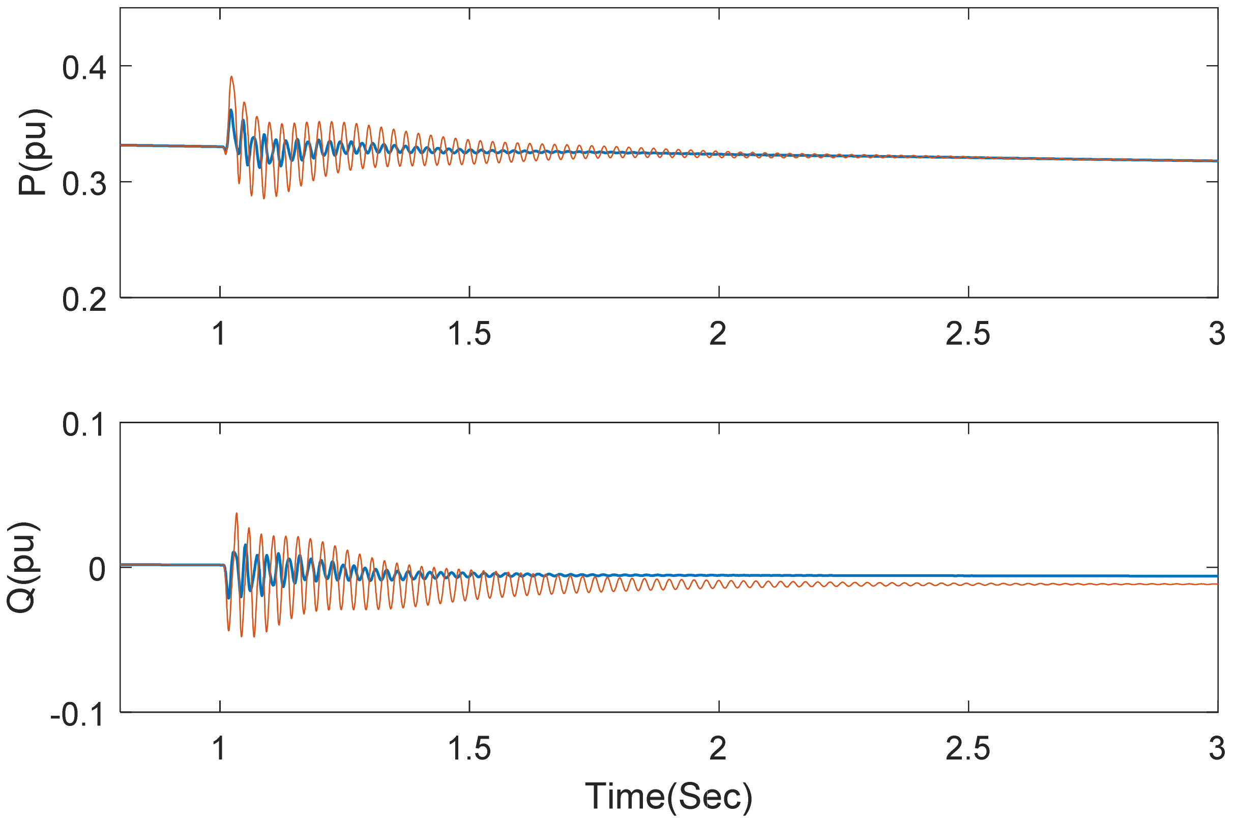
The performance for SSCI mitigation was compared to that of other control means based on PI control, partial feedback linearization, and first-order sliding mode. Figure 9 is the control structure of the classical double closed-loop PI scheme. The symbol * means reference value. Control parameters for PI controllers are K p = 0.1 , K Q = 0.83 , K i q = 1.2 , K i d = 5 , T p = 0.05 , T i q = 0.005 , T Q = 0.025 , and T i d = 0.0025 . Figure 10 shows active and reactive power responses under PI (Proportional Integral) controller [19] and the proposed method, when wind speed is 7 m/s and capacitance compensation is 60%. Growing oscillations are observed under PI control, while the effect for SSCI mitigation is good under the proposed method.
To compare the control performance under the proposed method and partial feedback linearization method [27], the implementation block diagram of the damping controller based on the partial feedback linearization method is shown in Figure 11. The relative control laws are represented as:
S q = L r f u d c v 1 + ω 1 i r d + R r f L r f i r q + v r q L r f S d = L r f u d c v 2 ω 1 i r q + R r f L r f i r d + v r d L r f
v 1 = k 1 p i r q _ r e f i r q + k 1 i 0 t i r q _ r e f i r q d t v 2 = k 2 p i r d _ r e f i r d + k 2 i 0 t i r d _ r e f i r d d t
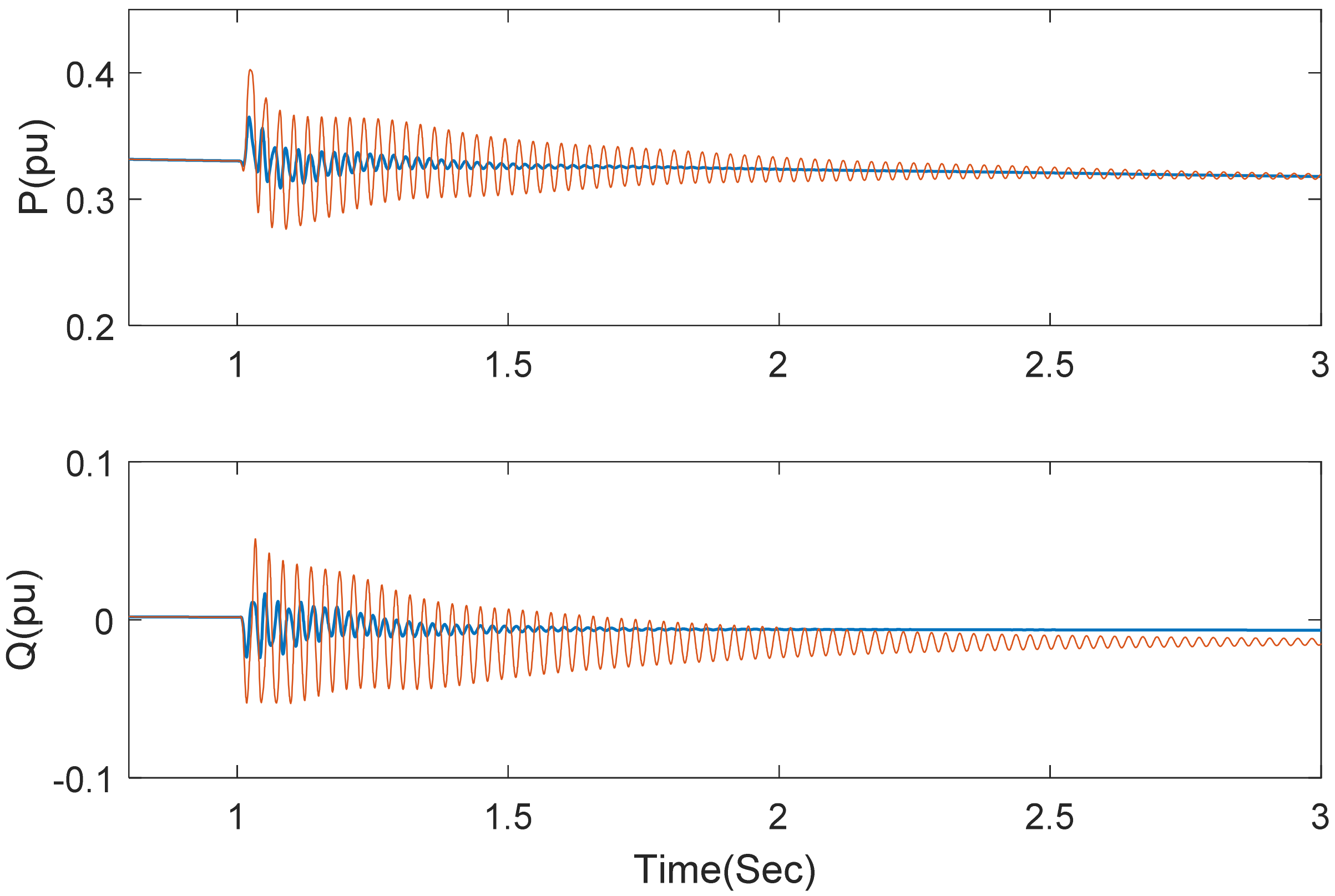
Figure 12 shows active power responses at 6 m/s wind speed and 60% compensation, and Figure 13 show the responses when parameter perturbation is considered. The variation ranges of Lm, Ls, LRSC, and RRSC are ± 50 % of the nominal values with combination of sine and cosine functions. The curves barely changed under the proposed method while it seems to be greatly affected under the partial feedback linearization method. This verified robustness to parameter perturbation of the proposed method.
Conventional first-order sliding mode control (SMC) damping scheme [9] is shown as Figure 14. The control laws are:
S r q = 2 L s u d c ( i r d ω 1 ( L m 2 L r r L s ) L m ( i s q R s u s q + L s i s d ω r ) + L s i r q R r r L r r L s i r d ω r i ˙ r q * ( L m 2 L r r L s ) ρ i r q s i g n ( σ i r q ) ( L r r L s L m 2 )
S r d = 2 L s u d c ( i r q ω 1 ( L m 2 L r r L s ) + L m ( i s d R s + u s d + L s i s q ω r ) + L s i r d R r r + L r r L s i r q ω r i ˙ r d * ( L m 2 L r r L s ) ρ i r d s i g n ( σ i r d ) ( L r r L s L m 2 )
where ρ i r q = 8.5 × 10 5 and ρ i r d = 2.3 × 10 6 .
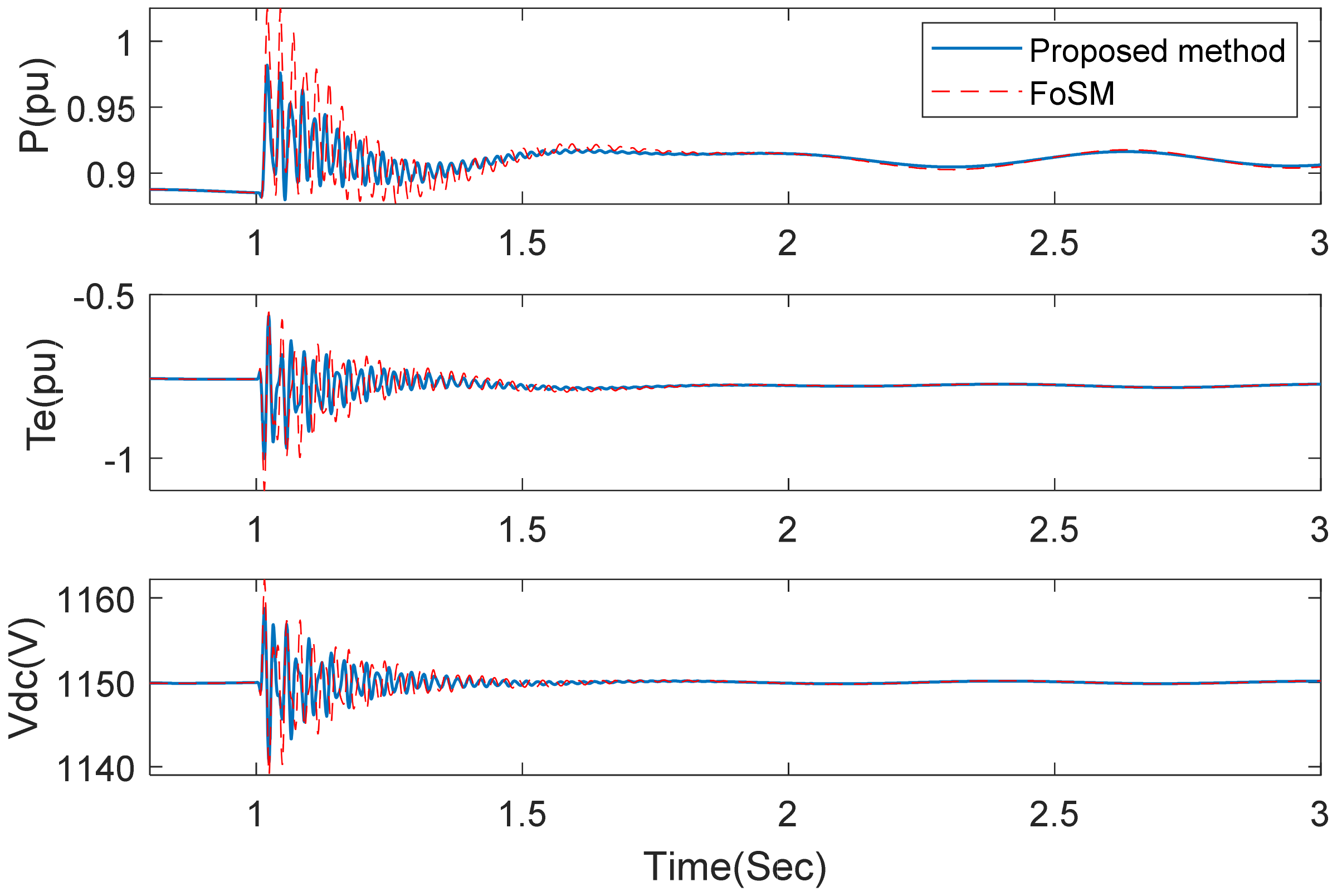
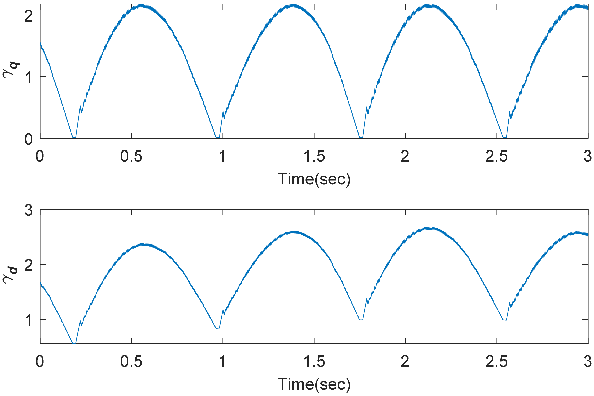
The transient responses of active power, electromagnetic torque, and DC link voltage under both the proposed method and first-order sliding mode method [9] are shown as Figure 15 when wind speed is 10 m/s and compensation is 60%. The oscillation processes both quickly disappeared after about 0.5 s, and SSCI mitigation was achieved. However, under the proposed method, the control chattering of RSC control input was greatly restrained, and the upper bounds of uncertainty derivatives were not needed. Figure 16 shows the regulating process of adaptive gains of super-twisting control.
For evaluating the control performance, two indices have been defined as follows:
R M S e i = 1 n s k = 1 n s e i 2 ,   R M S u i = 1 n s k = 1 n s u i 2
where n s , e i , and u i are the number of samples, root mean square (RMS) of tracking errors, and control quantities, respectively.
When the studied system works with series-compensated level of 60% and wind speed of 10 m/s, the RMS for tracking errors and control quantities are shown in Table 2, which exhibit superiority of the proposed method.

5. Conclusions

SSCI can severely influence stability of series-compensated DFIG-based wind power systems and damage electrical devices. This study proposes a novel VGSTSM damping control strategy for SSCI mitigation. After analyzing the series-compensated model and SSCI mechanism, it is assumed that SSCI were mainly caused by the interaction between current dynamics in the RSC side and the transmission line. Rotor current dynamics are desired to track the prescribed values from MPPT and grid demand. State feedback was firstly carried out in the control law design, and then super-twisting control algorithm was designed. Adaptive control gain was conceived via barrier function. Stability for the series-compensated system was proved, based on the Lyapunov function. The proposed method can achieve chattering suppression of RSC control signals. More importantly, control gains can indeed be adjusted according to uncertainty variation. It did not require the upper bound of uncertainty derivative in advance. Contrastive control simulations were verified to show superiority. Future works will focus on experimental realization.

Author Contributions

Conceptualization, R.M. and Y.H.; Funding acquisition, Y.H. and W.P.; Methodology, R.M.; Supervision, R.M.; Writing—original draft, R.M.; Writing—review & editing, Y.H. and W.P. All authors have read and agreed to the published version of the manuscript.

Funding

This research was funded by National Natural Science Foundation of China under Grant 61803230,61773015; A Project of Shandong Province Higher Educational Science and Technology Program under Grant J18KA330; University Outstanding Youth Innovation Team Development Plan of Shandong Province under Grant 2019KJN023; and Key R & D project of Shandong Province under Grant 2019GSF109076.

Institutional Review Board Statement

Not applicable.

Informed Consent Statemen

Not applicable.

Data Availability Statement

Data sharing not applicable.

Conflicts of Interest

The authors declare no conflict of interest.

References

  1. Mahalakshmi, R.; Thampatty, K.C.S. Design and implementation of modified RSC controller for the extenuation of sub-synchronous resonance oscillations in series compensated DFIG-based WECS. Int. Trans. Electr. Energy Syst. 2020, 30, e12396. [Google Scholar] [CrossRef]
  2. Han, Y.; Ma, R. Adaptive-Gain second-order sliding mode direct power control for wind-turbine-driven dfig under balanced and unbalanced grid voltage. Energies 2019, 12, 3886. [Google Scholar] [CrossRef] [Green Version]
  3. Suppioni, V.P.; Grilo, A.P.; Teixeira, J.C. Coordinated control for the series grid side converter-based DFIG at subsynchronous operation. Electr. Power Syst. Res. 2019, 173, 18–28. [Google Scholar] [CrossRef]
  4. Huang, P.H.; El Moursi, M.S.; Xiao, W.; Kirtley, J.L. Subsynchronous resonance mitigation for series-compensated DFIG-based wind farm by using two-degree-of-freedom control strategy. IEEE Trans. Power Syst. 2014, 30, 1442–1454. [Google Scholar] [CrossRef]
  5. Fan, L.; Zhu, C.; Miao, Z.; Hu, M. Modal analysis of a DFIG-based wind farm interfaced with a series compensated network. IEEE Trans. Energy Convers. 2011, 26, 1010–1020. [Google Scholar] [CrossRef]
  6. Jiao, Y.; Li, F.; Dai, H.; Nian, H. Analysis and mitigation of sub-synchronous resonance for doubly fed induction generator under VSG control. Energies 2020, 13, 1582. [Google Scholar] [CrossRef] [Green Version]
  7. Revel, G.; Alonso, D.M. Subsynchronous interactions in power networks with multiple DFIG-based wind farms. Electr. Power Syst. Res. 2018, 165, 179–190. [Google Scholar] [CrossRef]
  8. Yang, J.-W.; Sun, X.-F.; Chen, F.-H.; Lao, K.; He, Z.-Y. Subsynchronous resonance suppression strategy for doubly fed induction generators based on phase-shift average of rotor current. Int. Trans. Electr. Energy Syst. 2019, 29, e2831. [Google Scholar] [CrossRef]
  9. Karunanayake, C.; Ravishankar, J.; Dong, Z.Y. Nonlinear SSR damping controller for DFIG Based wind generators interfaced to series compensated transmission systems. IEEE Trans. Power Syst. 2020, 35, 1156–1165. [Google Scholar] [CrossRef]
  10. Ghaffarzadeh, H.; Mehrizi-Sani, A. Mitigation of subsynchronous resonance induced by a type III wind system. IEEE Trans. Sustain. Energy 2020, 11, 1717–1727. [Google Scholar] [CrossRef]
  11. Shair, J.; Xie, X.; Yan, G. Mitigating subsynchronous control interaction in wind power systems, Existing techniques and open challenges. Renew. Sustain. Energy Rev. 2019, 108, 330–346. [Google Scholar] [CrossRef]
  12. Velpula, S.; Thirumalaivasan, R.; Janaki, M. A Review on subsynchronous resonance and its mitigation techniques in DFIG based wind farms. Int. J. Renew. Energy Res. 2018, 8, 2275–2288. [Google Scholar]
  13. Wang, L.; Sun, X.; You, Y. DFIG wind farm modeling for subsynchronous control interaction Analysis. IEEJ Trans. Electr. Electron. Eng. 2018, 13, 253–261. [Google Scholar] [CrossRef]
  14. Yousuf, V.; Ahmad, A. Unit template-based control design for alleviation and analysis of SSR in power system using STATCOM. Electr. Power Compon. Syst. 2019, 47, 1805–1813. [Google Scholar] [CrossRef]
  15. Tung, D.D.; Dai, V.L.; Quyen, L.C. Subsynchronous resonance and facts-novel control strategy for its mitigation. J. Eng. 2019, 1–14. [Google Scholar] [CrossRef] [Green Version]
  16. Bhushan, R.; Chatterjee, K. Effects of parameter variation in DFIG-based grid connected system with a FACTS device for small-signal stability analysis. IET Gener. Transm. Distrib. 2017, 11, 2762–2777. [Google Scholar] [CrossRef]
  17. Boopathi, V.P.; Devi, R.P.K.; Ramanujam, R.; Dasan, S.G.B. Investigation of subsynchronous oscillations in grid connected Type-2 wind farm and its mitigation using STATCOM. J. Electr. Eng. 2017, 17, 10. [Google Scholar]
  18. Fan, L.; Kavasseri, R.; Miao, Z.L.; Zhu, C. Modeling of DFIG-based wind farms for SSR analysis. IEEE Trans. Power Deliv. 2010, 25, 2073–2082. [Google Scholar] [CrossRef]
  19. Fan, L.; Miao, Z. Mitigating SSR using DFIG-based wind generation. IEEE Trans. Sustain. Energy 2012, 3, 349–358. [Google Scholar] [CrossRef]
  20. Li, Y.; Fan, L.; Miao, Z. Replicating real-world wind farm SSR events. IEEE Trans. Power Deliv. 2020, 35, 339–348. [Google Scholar] [CrossRef]
  21. Ghafouri, M.; Karaagac, U.; Karimi, H.; Jensen, S.; Mahseredjian, J.; Faried, S.O. An LQR controller for damping of subsynchronous interaction in DFIG-based wind farms. IEEE Trans. Power Syst. 2017, 32, 4934–4942. [Google Scholar] [CrossRef]
  22. Leon, A.E.; Solsona, J.A. Sub-Synchronous interaction damping control for DFIG wind turbines. IEEE Trans. Power Syst. 2014, 30, 419–428. [Google Scholar] [CrossRef]
  23. Chen, A.; Xie, D.; Zhang, D.; Gu, C.; Wang, K. PI parameter tuning of converters for sub-synchronous interactions existing in grid-connected DFIG wind turbines. IEEE Trans. Power Electron. 2019, 34, 6345–6355. [Google Scholar] [CrossRef]
  24. Yao, J.; Wang, X.; Li, J.; Liu, R.; Zhang, H. Sub-Synchronous resonance damping control for series-compensated DFIG-based wind farm with improved particle swarm optimization algorithm. IEEE Trans. Energy Convers. 2019, 34, 849–859. [Google Scholar] [CrossRef]
  25. Rahimi, M. Dynamic performance assessment of DFIG-based wind turbines: A review. Renew. Sustain. Energy Rev. 2014, 37, 852–866. [Google Scholar] [CrossRef]
  26. Djoudi, A.; Bacha, S.; Iman-Eini, H.; Rekioua, T. Sliding mode control of DFIG powers in the case of unknown flux and rotor currents with reduced switching frequency. Int. J. Electr. Power Energy Syst. 2017, 96, 347–356. [Google Scholar] [CrossRef]
  27. Chowdhury, M.A.; Mahmud, M.A.; Shen, W.; Pota, H.R. Nonlinear controller design for series-compensated DFIG-based wind farms to mitigate subsynchronous control interaction. IEEE Trans. Energy Convers. 2017, 32, 707–719. [Google Scholar] [CrossRef]
  28. Chowdhury, M.A.; Shafiullah, G.M. SSR mitigation of series-compensated DFIG wind farms by a nonlinear damping controller using partial feedback linearization. IEEE Trans. Power Syst. 2018, 33, 2528–2538. [Google Scholar] [CrossRef]
  29. Penghan, L.; Jie, W.; Fei, W.; Li, H. Nonlinear controller based on state feedback linearization for series-compensated DFIG-based wind power plants to mitigate sub-synchronous control interaction. Int. Trans. Electr. Energy Syst. 2019, 29, e2682. [Google Scholar] [CrossRef] [Green Version]
  30. Wang, Y.; Wu, Q.; Yang, R.; Tao, G.; Liu, Z. H current damping control of DFIG based wind farm for sub-synchronous control interaction mitigation. Int. Trans. Electr. Energy Syst. 2018, 98, 509–519. [Google Scholar] [CrossRef]
  31. Ghafouri, M.; Karaagac, U.; Karimi, H.; Mahseredjian, J. Robust subsynchronous interaction damping controller for DFIG-based wind farms. J. Mod. Power Syst. Clean Energy 2019, 7, 1663–1674. [Google Scholar] [CrossRef] [Green Version]
  32. Xu, Y.; Zhao, S. Mitigation of subsynchronous resonance in series-compensated DFIG wind farm using active disturbance rejection control. IEEE Access 2019, 7, 68812–68822. [Google Scholar] [CrossRef]
  33. Liu, X.; Han, Y. Decentralized multi-machine power system excitation control using continuous higher-order sliding mode technique. Int. J. Electr. Power Energy Syst. 2016, 82, 76–86. [Google Scholar] [CrossRef]
  34. Susperregui, A.; Herrero, J.M.; Martinez, M.I.; Tapia-Otaegui, G.; Blasco, X. Multi-Objective optimisation-based tuning of two second-order sliding-mode controller variants for dfigs connected to non-ideal grid voltage. Energies 2019, 12, 3782. [Google Scholar] [CrossRef] [Green Version]
  35. Li, P.; Xiong, L.; Wu, F.; Ma, M.; Wang, J. Sliding mode controller based on feedback linearization for damping of sub-synchronous control interaction in DFIG-based wind power plants. Int. J. Electr. Power Energy Syst. 2019, 107, 239–250. [Google Scholar] [CrossRef]
  36. Li, P.; Xiong, L.; Wang, Z.; Ma, M.; Wang, J. Fractional-Order sliding mode control for damping of subsynchronous control interaction in DFIG-based wind farms. Wind Energy 2020, 23, 749–762. [Google Scholar] [CrossRef]
  37. Obeid, H.; Fridman, L.M.; Laghrouche, S.; Harmouche, M. Barrier function-based adaptive sliding mode control. Automatica 2018, 540–544. [Google Scholar] [CrossRef]
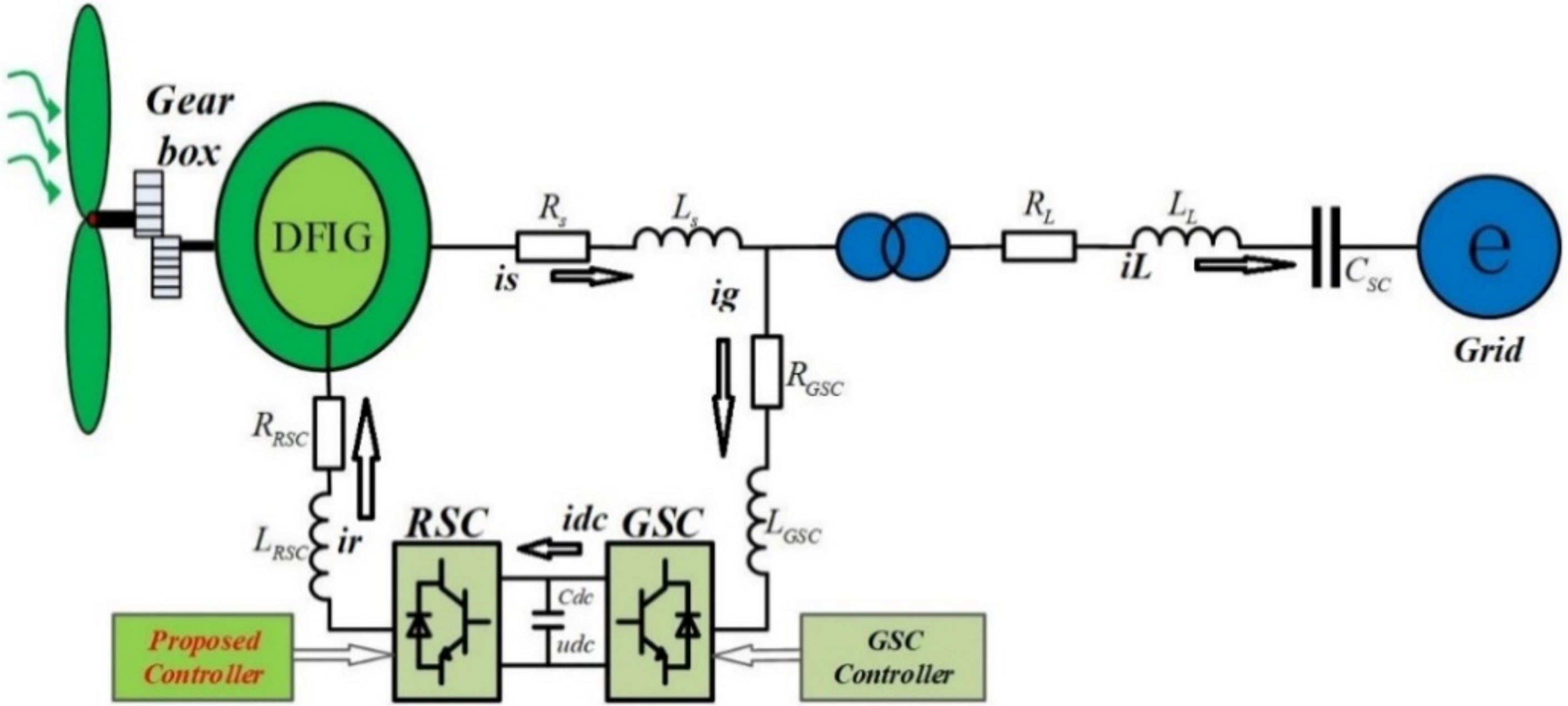
Figure 1. Structure of series-compensated doubly fed induction generator (DFIG)-based wind farm connected to grid.
Energies 14 00382 g001
Figure 2. Schematic diagram of the proposed damping control scheme.
Energies 14 00382 g002
Figure 3. Transient responses of active power, reactive power, and electromagnetic torque after 40% series compensation is switched.
Energies 14 00382 g003
Figure 4. Transient responses of rotor angular speed, DC bus voltage, and transmission line current after 40% series compensation is switched.
Energies 14 00382 g004
Figure 5. Transient responses of active power, reactive power, and electromagnetic torque after 85% series compensation is switched.
Energies 14 00382 g005
Figure 6. Transient responses of rotor angular speed, DC bus voltage, and transmission line current after 85% series compensation is switched.
Energies 14 00382 g006
Figure 7. Transient responses under wind speed of 11 m/s and series-compensated level of 85%.
Energies 14 00382 g007
Figure 8. Dynamic responses of active power, reactive power, and electromagnetic torque under three-phase short circuit fault.
Energies 14 00382 g008
Figure 9. Control structure of PI scheme.
Energies 14 00382 g009
Figure 10. Active and reactive responses under PI (blue) and the proposed method (red), with wind speed of 7 m/s and series-compensated level of 60%.
Energies 14 00382 g010
Figure 11. Implementation block diagram of the damping controller using partial feedback linearization method.
Energies 14 00382 g011
Figure 12. Active responses under the proposed method (blue) and partial feedback linearity (red) with wind speed of 6 m/s and compensation of 60%.
Energies 14 00382 g012
Figure 13. Active responses under the proposed method (blue) and partial feedback linearity (red) at 6 m/s wind speed and 60% compensation with parameter perturbation.
Energies 14 00382 g013
Figure 14. Conventional first-order SMC scheme.
Energies 14 00382 g014
Figure 15. The transient responses of active power, electromagnetic torque, and DC link voltage under both the proposed method and first-order sliding mode method.
Energies 14 00382 g015
Figure 16. Adaptive gains.
Energies 14 00382 g016
Table 1. Series-compensated DFIG-based wind power system parameters.
QuantityValue
Nominal power100 Mw
Rater voltage690 V
Rs0.0084 pu
Ls0.167 pu
HT2.5 pu
HG0.5 pu
Ks0.15 pu
RRSC0.0083 pu
LRSC0.1323 pu
RGSC0.0015 pu
LGSC0.151 pu
DC-lin capacitance10 mF
Nominal DC-link voltage1150 V
RL0.02 pu
LL0.0016 pu
CSC (at 45% compensation)42.61 uF
Table 2. Root mean square (RMS) for tracking errors and control quantities.
RMSurqRMSurdRMSeirqRMSeird
PI0.90610.89060.05910.0698
SMC0.80370.70910.05060.0593
VGSTSM0.60710.49210.03650.0361
Publisher’s Note: MDPI stays neutral with regard to jurisdictional claims in published maps and institutional affiliations.