Article

Research on Non-Pillar Coal Mining for Thick and Hard Conglomerate Roof

1
State Key Laboratory of Geomechanics & Deep Underground Engineering, China University of Mining & Technology, Beijing 100083, China
2
School of Mechanics and Civil Engineering, China University of Mining & Technology, Beijing 100083, China
3
School of Resource and Environmental Engineering, Shandong University of Technology, Zibo 255000, China
*
Author to whom correspondence should be addressed.
Energies 2021, 14(2), 299; https://doi.org/10.3390/en14020299
Submission received: 3 December 2020 / Revised: 2 January 2021 / Accepted: 4 January 2021 / Published: 7 January 2021
(This article belongs to the Section K: State-of-the-Art Energy Related Technologies)

Abstract

:
This article introduces a new non-pillar coal mining technology (i.e., Gob-side Entry Retaining by Roof Cutting (GERRC)) under the condition of thick and hard roofs. First, we theoretically analyzed the solution to the large suspension span of the thick and hard roof in coal mining. Three-Zone pre-split blasting design in non-pillar coal mining for thick and hard roofs was proposed, based on the principles of rock mechanics. After field experiments, the technology was successfully applied to the non-pillar coal mining of a huge thick conglomerate roof. This research supplements the non-pillar mining technology system. The proposed technologies and methods have strong applicability and have certain guiding significance for the safe and efficient mining of related coal mines.

1. Introduction

Gob-side Entry Retaining by Roof Cutting, a new non-pillar coal mining technology, is one of the latest and most widely used technology for Chinese coal mines [1,2,3,4,5,6,7,8,9,10,11,12]. Compared with general coal mining methods, non-pillar mining has obvious technical advantages. For example, using this method can realize the economic benefits of digging one less roadway for each working face and recovering one more coal pillar. At the same time, this technology greatly reduces the roof disaster problem and reduces hazards such as ventilation and gas accumulation. This technology has significant safety benefits and social impacts [3].
There are basic research [13,14,15,16], laboratories [17,18,19], new inventions [20,21], and field engineering [22,23,24,25] around this new type of coal mining. At present, this new non-pillar mining technology has been successfully applied to various geological conditions and different roof conditions. However, there are few in-depth studies on non-pillar coal mining with thick and hard roofs.
Thick and hard roofs are widely distributed in coal mines, which account for 1/3 of the proportion of coal mines in China. These rock layers are generally thick-layered as a whole, and the bedding, joints, and cracks in the rock mass are not developed. A common disaster for thick and hard roofs is that they fail to collapse in time, resulting in large-area overhangs of the roof, posing safety hazards to coal mines. Thick and hard roof mining generally requires special technology to weaken the roof [26,27,28]. For non-pillar coal mining, it is necessary to control the collapse of the roof in the goaf. The study of thick and hard roof control technology is of great significance for the promotion of non-pillar coal mining.

2. Non-Pillar Coal Mining (110-Method)

In general longwall coal mining methods, two roadways need to be excavated in advance for a working face [29]. During the mining process, the two roadways are collapsed as the rocks in the mined-out area collapsed. To avoid the impact of the supporting pressure of the coal pillars on the overlying rock on the coal mining activities of the new work, it is necessary to leave a sufficient distance of coal pillars [30,31,32,33,34,35], to re-plan the working face, and excavate two roadways at the next working face. This kind of coal mining method also is known as the 121-method, as illustrated in Figure 1.
The new non-pillar coal mining method makes full use of rock mechanics. Through certain technical measures (Gob-side Entry Retaining by Roof Cutting (GERRC)), the roadway of the working face is fully relieved and effectively supported during the mining process, and the roadway of this working face is reserved and can be used continuously on the next working face.
This new mining method is known as the 110-method, and it avoids wasted coal pillars, saves an excavation roadway, and optimizes mining time. It is a scientific mining method that greatly promotes coal enterprises to reduce costs and increase benefits.

3. Design and Treatment of Thick and Hard Roof in Non-Pillar Coal Mining

In the process of non-pillar coal mining, the reserved roadway needs to be fully and effectively relieved of pressure, which requires the roof of the mining area to collapse in time, thereby reducing the pressure on the roadway. In this case, the collapsed gangue can timely support the roadway. However, the thick and hard roof structure will cause the roof cantilever to be large, and the roof will not collapse in time, which causes a big safety hazard to the roadway remaining along the goaf. Certain measures need to be taken to reduce the cantilever length.

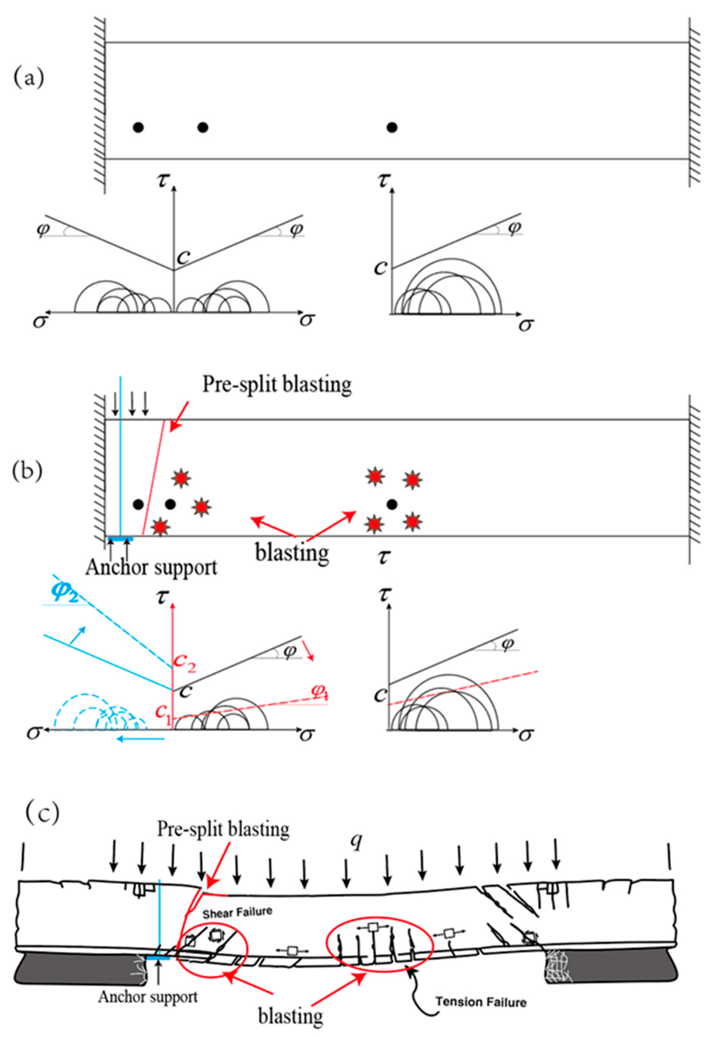
3.1. The Influence of Thick and Hard Characteristic on Roof Span

In the coal mining process, according to the roof force, it can be simply regarded as a beam structure model with uniformly distributed loads. As the working face advances, the goaf roof will experience three states: Fixed support at both ends, cantilever beam, and simply supported beam. The three states correspond to the initial collapse of the roof during coal mining, roof first weighting, and roof periodic caving.
As shown in the Figure 2, according to material mechanics, the relationship between span and beam properties can be easily calculated. From the calculation results, the influence of the thick and hard roof on the beam span can be understood.
(a) In the case of the two ends are fixed, the following formulas will be obtained:
M max = - q L 2 12
σ max = M max W z = M max h 2 6 = 6 M max h 2 = q L 2 2 h 2
σ max = R T
L max = h 2 R T q
In the formula, M max is the maximum bending moment of the beam, σ max is tensile stress at the maximum bending moment, q is overburden load, L is beam span, h is the thickness of the beam, R T is ultimate tensile failure strength of beam element, L max is the maximum span.
(b) In the case of a cantilever beam, similar calculations can be obtained:
M max = q L 2 2
σ max = M max W z = M max bh 2 6 = 6 M max bh 2 = 3 q L 2 bh 2
σ max = R T
L max = h R T 3 q
(c) In the case of a simply supported beam, the following formulas will be obtained:
M max = q L 2 8
σ max = M max W z = M max h 2 6 = 6 M max bh 2 = 3 q L 2 4 h 2
σ max = R T
L max = 2 h R T 3 q
Through the above calculations, it can be seen that for the three types of beams formed by the mined-out roof, the roof beam span is proportional to the thickness and hardness of the roof. That is:
L max h R t
As the thickness and strength of the roof increase, the self-supporting span of the roof show a certain correlation and increase synchronously. For the thick and hard roof, the initial collapse, roof first weighting, and roof periodic caving span are several times more than the thin weak roof. The coal mining process requires treatments of the thick and hard roof.

3.2. Technical Measures for Thick and Hard Roof Non-Pillar Mining

The thick and hard roof is not easy to collapse, and it needs to be strengthened for support and blasting treatment in non-pillar coal mining. On the one hand, the roof stability of the roadway is strengthened by support, and on the other hand, the instability and collapse of the roadway in the goaf will be accelerated by blasting.
As shown in Figure 3, the stress Mohr circle and Coulomb strength curve at a point on the beam are selected to analyze the mechanical behavior of the roof in the thick and hard roof.
Figure 3a shows the force of the beam without any treatment. At this time, the Coulomb strength curve of the element node is above the Mohr circle, the rock at this point will not damage, and the beam can be self-balanced and stable.
Figure 3b shows the treatment of roadway roof using anchor support and special blasting technology during non-pillar mining. First, cut off the roof on the side of the roadway and the roof of the stope with pre-split blasting, reinforce the roadway with anchor cables and use blasting to crack the roof on one side of the goaf. Because the roof of the roadway compresses the rock mass due to the anchor cable support, the radius of the stress Mohr circle becomes smaller. At the same time, the anchor cable support will increase the c value and the ϕ value of the rock itself, which improves the coulomb strength of the rock, so the roof of the roadway is more stable and not easy to damage. For the roof of the mined-out area, the blasting of the roof reduces the c value and the ϕ value of the rock mass, so that the Coulomb strength curve drops, causing damage to the internal elements of the beam, and the beam collapses.
Select two places to blast the roof. One is close to the middle of the beam, and the entire beam breaks faster. The other is close to the pre-splitting joints, which can reduce the size of the collapsed gangue in the goaf on the side of the roadway, and at the same time accelerate the collapse speed and roadway forming speed.
Figure 3c visually expresses the shape of the roof after supporting, cut-off roof blasting and deep hole fragmentation roof blasting. It can be seen from the figure that after the above treatment of the roof, cracks of different degrees appear in the roof, which can accelerate the collapse of the roof in the goaf and reduce the fragmentation of the collapsed rock near the roadway. The use of anchor support and roof-cutting blasting can increase the stability of the roadway, thereby increasing the safety of non-pillar mining.

3.3. Three-Zone Pre-Split Blasting Design in Non-Pillar Coal Mining

For the thick and hard roof non-pillar coal mining, the three-zone pre-cracking technology is proposed. Ahead of the working face, the three-zone pre-splitting of the roof in non-pillar mining can reduce the span of the roof in the goaf and realize the safe preservation of the roadway.
As shown in Figure 4, firstly, for the roadway roof cut in Zone I, this technology is a key technology in general non-pillar mining. For non-pillar mining with thick and hard roofs, deep hole blasting in Zone II and Zone III is added. According to the periodic collapse of the roof, deep hole blasting is carried out at regular intervals L, as shown in Figure 4a.
The purpose of deep hole blasting in Zone II is to pre-crack the roof in a certain step, create cracks, and weaken the strength of the roof, to reduce the span of the roof and the pressure during its collapse. The purpose of deep hole blasting in Zone III is to break the roof near the roadway, which can reduce the size of the gangue, reduce the impact on the roadway, and accelerate the collapse of the roof to quickly realize the roadway retention.
Figure 4a,b are plan views, and Figure 4c,d are three-dimensional views of the design. This technology is operated in advance of the working face and does not affect coal mine production.

4. Engineering Background and Design

4.1. Project Overview

The test working face is in Donglin Coal Mine, located in Inner Mongolia in northeastern China. As shown in Figure 5, it is a modern comprehensive mechanized mining coal mine with an annual output of 1.2 million tons. The test working face is W1-106 working face, as shown in Figure 6, a total of 1259 m of roadways are reserved. The roadway has a rectangular section of 3.8 m × 3.0 m, and it is supported by bolts and nets.
The lithology above the coal seam is conglomerate. The thickness ranges from 14.51 to 136.0 m, with an average of 81.63 m. The diagenetic consolidation is good, the quality grade is medium to good, the rock has high shear and compressive strength, and the roof is not easy to collapse. The softening coefficient is 0.17 to 0.99, with an average of 0.44. It is a rock that is not easy to soften. The falling rock has a large lumpiness and strong integrity. When forming the roof of the coal seam, it is a hard roof that does not fall easily, and the roof is suspended during the mining process.
Figure 6 shows the shape of the falling gangue and the suspended roof behind the working face support.

4.2. Design Parameters of Non-Pillar Mining

The lithology distribution of the roof is one of the most important information basis for the design of key parameters of non-pillar mining. The roof lithology profile is made within 15 m above the roof of the roadway, as can be seen in Figure 7a. The on-site drilling construction shows that the old roof at both ends of the roadway is thick and hard sandy conglomerate, which is gray-white to dark gray, with strong integrity, dense structure, and round gravel. The roof in the middle of the roadway is thin sandy conglomerate, and the roof is seriously eroded and muddy, showing rusty yellow, cemented mud, and loose structure.
This article only discusses the design of the thick and hard roof section. According to roof lithology, the length of constant resistance large deformation anchorage (CRLDA) is designed to be 11.3 m, and two rows of anchor cables are designed. The length of the directional cut-off roof pre-splitting blasting slit hole is designed to be 9 m. Design parameters can be seen in Figure 7b,c is a construction site picture according to design parameters.

4.3. Three-Zone Pre-Split Design Parameter

As shown in Figure 8a, the blasting design is used for deep-hole blasting in Zone II and Zone III every 15 m.
Three deep holes are designed for Zone II blasting, which is perpendicular to the direction of the roadway. Five deep holes are designed in Zone III, along the back of the roadway, at a certain angle to the goaf. Roof cutting (Zone I) and deep hole blasting (Zone II and Zone III) use different professional drilling rigs to complete the drilling construction, and two kinds of blasting also use different techniques, as shown in Figure 8b–d.
The charging parameters of Zone I are shown in Table 1. In Zone I, cut-off roof blasting, explosives with Φ32 × 200 mm, 200 g/roll, 50 mm blast hole diameter are selected. Blasting needs to use 6 specially made concentrated energy tubes, and the charging method is 5-5-4-3-2. The details of this blasting method can be found in similar related documents [2,4,11], which will not be repeated here.
The charging parameters of Zone II and Zone III are shown in Table 2; Table 3. The selected explosive is Φ60 × 500 mm, 1.5 kg/roll, and the blast hole diameter is 75 mm. At this time, the blasting does not need to add a concentrated energy tube, only needs to continuously charge explosives in the holes according to the designed parameter.

5. Field Test Result

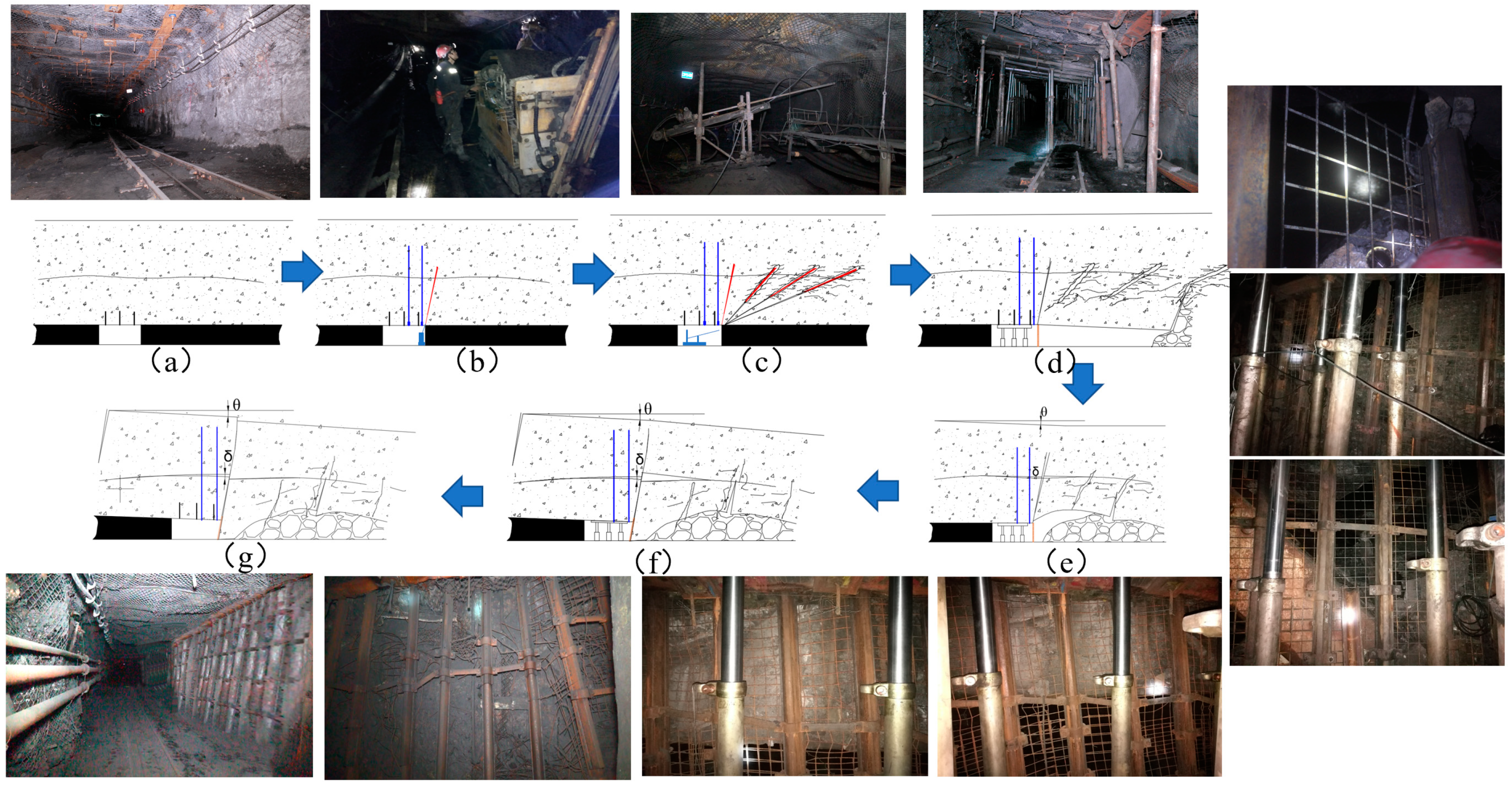
5.1. Non-Pillar Mining Process

Figure 9a–g show the entire process of thick and hard roof non-pillar mining. It can be seen that the complete process of the smooth collapse of the thick hard conglomerate roof after pre-cracking blasting and deep hole blasting measurement. The overall construction sequence is: Applying constant resistance and large deformation anchor cable (CRLDA) → roof pre-splitting and slitting (zone I) → roof deep hole blasting (zone II zone III) → hydraulic supports in the roadway → after the working face is mined, the roof of the goaf gradually collapses → the roof of the goaf completely collapses → the roadway is stable, and the hydraulic supports are withdrawn.
The specific construction parameters have been explained in detail in Section 4. In the on-site construction process, for areas where the roof is faulted or broken, it is necessary to appropriately increase the density of anchor cables and support in the roadway. According to relevant literature knowledge and field practice, the magnitude of tectonic stress will affect the roof collapse. However, when the pre-splitting deep hole blasting distance is 15 m, it can satisfy the roof collapse in time after coal mining, so no more in-depth research has been carried out. If the roof does not collapse in time in some place, it is possible to appropriately increase the support, such as with wood piles in the roadway, to increase the roof cutting ability and stability of the roadway.
The overall construction sequence does not affect each other, and the field application is good. It shows that under the condition of thick and hard conglomerate roof, the use of three-zone pre-splitting roof blasting technology can achieve safe non-pillar mining.

5.2. Field Pre-Splitting Blasting Effect

Figure 10 shows the results of roof-cut pre-cracking (Zone I). After blasting, as shown in Figure 10a, a through crack is formed on the surface of the roof. This crack cuts off the roof of the roadway and the roof of the goaf.
Figure 10b,c show the result of the blasting cracks after the pre-split blasting viewed from the inside of the hole. There are two clear symmetrical cracks in the hole, which extend from the bottom of the hole to the top of the hole. Two cracks in the hole cut the roof along the cracks in the hole. The cracks in the multiple holes propagate and penetrate each other to achieve the effect of cutting off the roof.
Figure 11 shows the comparison of roof collapse before and after deep hole pre-splitting blasting (Zone II and Zone III). As shown in Figure 11a,b, the roof of the goaf is viewed from the front of the hydraulic support. When deep hole pre-splitting blasting is not used, the roof behind the support is suspended, and the roof has no tendency to collapse. After adopting deep-hole pre-splitting blasting, the large gangue collapsed to fill the goaf. Figure 11c,d show the roof collapse and filling condition from the back of the hydraulic support. In the absence of deep-hole pre-splitting blasting, the rear roof of the hydraulic support is suspended in a large area, with a suspension span of 20 to 30 m. After adopting deep-hole pre-splitting blasting, the collapsed roof gangue can fill the goaf, and the suspended length of the uncollapsed roof is reduced to 10 m.

5.3. Pressure Monitoring of Hydraulic Support

By monitoring the pressure of the working face hydraulic support, the effect of pre-splitting blasting is analyzed. Figure 12a shows the time–space pressure cloud graph curve of pressure with the mining distance of the working face. It can be seen that the periodic pressure is obvious, with a certain distance. Each cycle of the roof pressure represents the periodic break of the roof. When the pressure reaches its peak during the cycle, it indicates that the roof is broken.
Figure 12b,c compare the pressure curves of 1# hydraulic support and 36# hydraulic support. By analyzing the pressure of the 1# hydraulic support, it can be known that the initial pressure distance is 40.8 m, the periodic pressure distance is 17–23 m, the average pressure of the support is 20.8 MPa, and the maximum is 28.65 MPa. The designed deep-hole blasting distance of Zone II is 15 m, a reasonable design parameter, which can crush rocks within a period of pressure distance. Blasting reduces the size of the rock and reduces the strength of the incoming pressure.
Through the analysis of the pressure of the 36# hydraulic support, it can be known that the initial pressure distance is 47.2 m, the periodic pressure distance is 22–30 m, the average pressure of the support is 29.1 MPa, and the maximum is 47.2 MPa. Zone III deep hole blasting will also shorten the distance and intensity of periodic pressure.

5.4. Economic Benefit

In W1-106 working face, compared with mining with coal pillars, the new technology of cutting roof and pressure relief without coal pillars can reduce the excavation of roadways by 1350 m, avoid waste of a 9 m wide coal pillar, and produce huge economic benefits.
After adopting the new technology, calculated according to the 9 m wide roadway protection coal pillar, the mining height is 2.8 m, the recovered coal pillar is 60,900 tons, the commercial coal output is 31,000 tons, the average price per ton of coal is 887 yuan/ton, and the recovered coal resource benefit is about 27.5 million yuan ($4.21 million).
The economic benefit of reducing the excavation of a 1350 m roadway is 8.24 million yuan ($1.26 million).
Subtracting the above benefits from the construction materials, equipment, scientific research cost, staff salaries, and other costs of non-pillar mining, the total economic benefits obtained are 22 million yuan ($3.37 million).

6. Conclusions

The following conclusions were obtained through this research:
  • The properties of the thick and hard roof beams result in a large roof span, and the roof is not easy to collapse. The use of support and blasting methods can change the properties of the beams to preserve the roof of the roadway and accelerate the collapse of the roof in the goaf.
  • A Three-Zone pre-splitting method is designed for the thick and hard roof non-pillar coal mining. Compared with general non-pillar mining, this method not only requires directional pre-splitting to cut off the roof, but also add deep hole pre-splitting blasting of the roof in the goaf. Deep hole pre-cracking the roof near the reserved roadway and the roof in the middle of the mined-out area can accelerate the goaf roof fracture and smoothly accelerate the roof collapse.
  • The field test results are good, the test roof cracks are obvious, the directional pre-splitting effectively cuts off the test roof, and the deep hole blasting shortens the periodic pressure distance. The results show that the test roof of the goaf can collapse in time after adopting the new technology, which greatly reduces the pressure of retaining the roadway, and increases the safety of non-pillar coal mining. Using new technology, the entire project has achieved huge economic benefits.

Author Contributions

M.H. and J.W. conceived and designed the research. Z.M. and X.L. performed field tests; X.L. analyzed the data and wrote the paper. All authors have read and agreed to the published version of the manuscript.

Funding

This research received no external funding.

Data Availability Statement

No new data were created or analyzed in this study. Data sharing is not applicable to this article.

Acknowledgments

This work is supported by the National Natural Science Foundation of China (No. 51574248, No. 51674265) and the State Key Research Development Program of China (No. 2016YFC0600900), which are gratefully acknowledged.

Conflicts of Interest

The authors declare no conflict of interest.

References

  1. Guo, P.; He, M.; Wang, J.; Zhou, H. Test Study on Multi Tray Bolt in Gob-Side Entry Retaining Formed by Roof Cut and Pressure Releasing. Geotech. Geol. Eng. 2017, 35, 2497–2506. [Google Scholar] [CrossRef]
  2. He, M.; Gao, Y.; Yang, J.; Gong, W. An Innovative Approach for Gob-Side Entry Retaining in Thick Coal Seam Longwall Mining. Energies 2017, 10, 1785. [Google Scholar] [CrossRef] [Green Version]
  3. He, M.; Zhu, G.; Guo, Z. Longwall mining “cutting cantilever beam theory” and 110 mining method in China—The third mining science innovation. J. Rock Mech. Geotech. Eng. 2015, 7, 483–492. [Google Scholar] [CrossRef] [Green Version]
  4. Ma, Z.; Wang, J.; He, M.; Gao, Y.; Hu, J.; Wang, Q. Key technologies and application test of an innovative noncoal pillar mining approach: A case study. Energies 2018, 11, 2853. [Google Scholar] [CrossRef] [Green Version]
  5. Wang, Q.; He, M.; Yang, J.; Gao, H.; Jiang, B.; Yu, H. Study of a no-pillar mining technique with automatically formed gob-side entry retaining for longwall mining in coal mines. Int. J. Rock Mech. Min. Sci. 2018, 110, 1–8. [Google Scholar] [CrossRef]
  6. Wang, Q.; Qin, Q.; Jiang, B.; Jiang, Z.; He, M.; Li, S.; Wang, Y. Geomechanics model test research on automatically formed roadway by roof cutting and pressure releasing. Int. J. Rock Mech. Min. Sci. 2020, 135, 104506. [Google Scholar] [CrossRef]
  7. Wang, Y.; Gao, Y.; Wang, E.; He, M.; Yang, J. Roof Deformation Characteristics and Preventive Techniques Using a Novel Non-Pillar Mining Method of Gob-Side Entry Retaining by Roof Cutting. Energies 2018, 11, 627. [Google Scholar] [CrossRef]
  8. Wang, Y.; Yang, J.; He, M.; Tian, X.; Liu, J.; Xue, H.; Huang, R. Test of a liquid directional roof-cutting technology for pressure-relief entry retaining mining. J. Geophys. Eng. 2019, 16, 620–638. [Google Scholar] [CrossRef] [Green Version]
  9. Zhang, X.; He, M.; Yang, J.; Wang, E.; Zhang, J.; Sun, Y. An Innovative Non-Pillar Coal-Mining Technology with Automatically Formed Entry: A Case Study. Engineering 2020, 11, 1315–1329. [Google Scholar] [CrossRef]
  10. Zhang, X.; Hu, J.; Xue, H.; Mao, W.; Gao, Y.; Yang, J.; He, M. Innovative approach based on roof cutting by energy-gathering blasting for protecting roadways in coal mines. Tunn. Undergr. Space Technol. 2020, 99, 103387. [Google Scholar] [CrossRef]
  11. Zhang, X.; Pak, R.Y.; Gao, Y.; Liu, C.; Zhang, C.; Yang, J.; He, M. Field experiment on directional roof presplitting for pressure relief of retained roadways. Int. J. Rock Mech. Min. Sci. 2020, 134, 104436. [Google Scholar] [CrossRef]
  12. Zhu, G.; Sousa, R.; He, M.; Zhou, P.; Yang, J. Stability Analysis of a Non-Pillar-Mining Approach Using a Combination of Discrete Fracture Network and Discrete-Element Method Modeling. Rock Mech. Rock Eng. 2020, 53, 269–289. [Google Scholar] [CrossRef]
  13. Sun, X.; Liu, X.; Liang, G.; Wang, D.; Jiang, Y. Key parameters of gob-side entry retaining formed by roof cut and pressure releasing in thin coal seams. Chin. J. Rock Mech. Eng. 2014, 33, 1449–1456. [Google Scholar]
  14. Guo, Z.; Wang, J.; Cao, T.; Chen, L.; Wang, J. Research on key parameters of gob-side entry retaining automatically formed by roof cutting and pressure release in thin coal seam mining. J. China Univ. Min. Technol. 2016, 45, 879–885. [Google Scholar]
  15. Ma, X.; He, M.; Li, X.; Li, E.; Hu, C.; Gao, R. Deformation mechanism and control measures of overlying strata with gob-side entry retaining formed by roof cutting and pressure releasing. J. China Univ. Min. Technol. 2019, 48, 474–483. [Google Scholar]
  16. Gao, Y.; Guo, Z.; Yang, J.; Wang, J.; Wang, Y. Steady analysis of gob-side entry retaining formed by roof fracturing and control techniques by optimizing mine pressure. China Coal Soc. 2017, 42, 1672–1681. [Google Scholar]
  17. He, M.; Gong, W.; Wang, J.; Qi, P.; Tao, Z.; Du, S.; Peng, Y. Development of a novel energy-absorbing bolt with extraordinarily large elongation and constant resistance. Int. J. Rock Mech. Min. Sci. 2014, 67, 29–42. [Google Scholar] [CrossRef]
  18. He, M.; Li, C.; Gong, W.; Sousa, L.; Li, S. Dynamic tests for a Constant-Resistance-Large-Deformation bolt using a modified SHTB system. Tunn. Undergr. Space Technol. 2017, 64, 103–116. [Google Scholar] [CrossRef]
  19. Wang, J.; Zhu, D.; Gong, W.; He, M.; Gao, R. Physical simulation experiment on the movement of rock strata upon automatic roadway forming by roof cutting and pressure releasing. Chin. J. Rock Mech. Eng. 2018, 37, 2536–2547. [Google Scholar]
  20. He, M. Constant-Resistance Large-Deformation Anchor Rod. U.S. Patent 8,974,151, 10 March 2015. [Google Scholar]
  21. He, M.; Guo, Z. Fractured Roof 110 Mining Method Entry-Side Anti-Collapsed Structure. U.S. Patent 10,677,055, 9 June 2020. [Google Scholar]
  22. Gao, Y.; Wang, Y.; Yang, J.; Zhang, X.; He, M. Meso-and macroeffects of roof split blasting on the stability of gateroad surroundings in an innovative nonpillar mining method. Tunn. Undergr. Space Technol. 2019, 90, 99–118. [Google Scholar] [CrossRef]
  23. Hu, J.; He, M.; Wang, J.; Ma, Z.; Wang, Y.; Zhang, X. Key parameters of roof cutting of gob-side entry retaining in a deep inclined thick coal seam with hard roof. Energies 2019, 12, 934. [Google Scholar] [CrossRef] [Green Version]
  24. Ma, X.; He, M.; Wang, J.; Gao, Y.; Zhu, D.; Liu, Y. Mine strata pressure characteristics and mechanisms in gob-side entry retention by roof cutting under medium-thick coal seam and compound roof conditions. Energies 2018, 11, 2539. [Google Scholar] [CrossRef] [Green Version]
  25. He, M.; Ma, X.; Wang, J.; Zhang, J.; Liu, Y. Feature analysis of working face strata pressure with roof cutting pressure releasing in medium-thick seam and compound roof condition. Chin. J. Rock Mech. Eng. 2018, 37, 2425–2434. [Google Scholar]
  26. Yang, J.; Liu, C.; Yu, B. Application of confined blasting in water-filled deep holes to control strong rock pressure in hard rock mines. Energies 2017, 10, 1874. [Google Scholar] [CrossRef] [Green Version]
  27. Wang, F.; Tu, S.; Yuan, Y.; Feng, Y.; Chen, F.; Tu, H. Deep-hole pre-split blasting mechanism and its application for controlled roof caving in shallow depth seams. Int. J. Rock Mech. Min. Sci. 2013, 64, 112–121. [Google Scholar] [CrossRef]
  28. He, H.; Dou, L.; Fan, J.; Du, T.; Sun, X. Deep-hole directional fracturing of thick hard roof for rockburst prevention. Tunn. Undergr. Space Technol. 2012, 32, 34–43. [Google Scholar] [CrossRef]
  29. Peng, S.S. Longwall Mining; CRC Press: Boca Raton, FL, USA, 2019. [Google Scholar]
  30. Ghasemi, E.; Ataei, M.; Shahriar, K. An intelligent approach to predict pillar sizing in designing room and pillar coal mines. Int. J. Rock Mech. Min. Sci. 2014, 65, 86–95. [Google Scholar] [CrossRef]
  31. Jaiswal, A.; Shrivastva, B. Numerical simulation of coal pillar strength. Int. J. Rock Mech. Min. Sci. 2009, 46, 779–788. [Google Scholar] [CrossRef]
  32. Poulsen, B. Coal pillar load calculation by pressure arch theory and near field extraction ratio. Int. J. Rock Mech. Min. Sci. 2010, 47, 1158–1165. [Google Scholar] [CrossRef]
  33. Poulsen, B.; Shen, B.; Williams, D.; Huddlestone-Holmes, C.; Erarslan, N.; Qin, J. Strength reduction on saturation of coal and coal measures rocks with implications for coal pillar strength. Int. J. Rock Mech. Min. Sci. 2014, 71, 41–52. [Google Scholar] [CrossRef]
  34. Trueman, R.; Lyman, G.; Cocker, A. Longwall roof control through a fundamental understanding of shield–strata interaction. Int. J. Rock Mech. Min. Sci. 2009, 46, 371–380. [Google Scholar] [CrossRef]
  35. Wattimena, R.; Kramadibrata, S.; Sidi, I.; Azizi, M. Developing coal pillar stability chart using logistic regression. Int. J. Rock Mech. Min. Sci. 2013, 58, 55–60. [Google Scholar] [CrossRef]
Figure 1. Schematic diagram of traditional coal mining (121-method, left half of the figure) and non-pillar mining with Gob-side Entry Retaining by Roof Cutting (GERRC) (110-method, right half of the figure).
Energies 14 00299 g001
Figure 2. Three types of beams are formed in the suspended roof during coal mining.
Energies 14 00299 g002
Figure 3. Mechanical analysis of the treatment of thick and hard roof of non-pillar mining (a) Mechanics analysis of roof without any measures (b) Mechanics analysis of roof after taking blasting and supporting measures (c) Schematic diagram of roof cracks and collapse after taking blasting and supporting measures.
Energies 14 00299 g003
Figure 4. Three-Zone pre-split sketch design (a) Plan view of the design (b) Designed facade front view (c) View of 3D sketches from behind (d) View of 3D sketches from front.
Energies 14 00299 g004
Figure 5. Location and appearance of the test mine.
Energies 14 00299 g005
Figure 6. The layout of the test working face and lithology of the collapsed roof.
Energies 14 00299 g006
Figure 7. Non-pillar mining design parameters and site construction (a) The roof lithology profile (b) Design parameters (c) Construction site picture according to design parameters.
Energies 14 00299 g007
Figure 8. Three-Zone pre-split design parameter and site construction (a) Plan view of the blasting design (b) 3-D Sketch view of the blasting design (c) Roof cutting Blasting construction (Zone I) (d) Deep hole blasting (Zone II/Zone III).
Energies 14 00299 g008
Figure 9. Non-pillar mining process (a) Applying constant resistance and large deformation anchor cable (CRLDA) (b) Roof pre-splitting and slitting (zone I) (c) Roof deep hole blasting (zone II zone III) (d) Hydraulic supports in the roadway (e) After the working face is mined, the roof of the goaf gradually collapses (f) The roof of the goaf completely collapses (g) The roadway is stable, and the hydraulic supports are withdrawn.
Energies 14 00299 g009
Figure 10. Roof-Cut presplitting blasting (a) A crack is formed on the surface of the roof (b) Cracks viewed from the inside of the hole (c) An expanded graph of cracks viewed from the inside of the hole.
Energies 14 00299 g010
Figure 11. Roof collapse conditions before and after deep-hole blasting (a) The roof of the goaf is suspended, viewed from the front of the hydraulic support (b) The roof of the goaf is collapsed, viewed from the front of the hydraulic support (c) The roof of the goaf is suspended, viewed from the back of the hydraulic support (d) The roof of the goaf is collapsed, viewed from the back of the hydraulic support.
Energies 14 00299 g011
Figure 12. The hydraulic support pressure curve (a) Time–space pressure cloud graph of hydraulic support (b) 1# hydraulic support press curve (c) 36# hydraulic support press curve.
Energies 14 00299 g012
Table 1. Pre-splitting blasting parameters (Zone I).
NoBlast Hole Length (m)Angle with Floor (°)Blast Hole Diameter (mm)Charge Length (m)Charge Weight (kg)Number of DetonatorsSealing Mud Length (m)Charge Method
O975507.53.612.555432
Table 2. Deep hole blasting parameters (Zone II).
NoBlast Hole Length (m)Angle with Floor (°)Angle with Roadway (°)Blast Hole Diameter (mm)Charge Length (m)Charge Weight (kg)Number of DetonatorsSealing Mud Length (m)
A5111907534102217
B321690752266211
C22239075154227
Table 3. Deep hole blasting parameters (Zone III).
NoBlast Hole Length (m)Angle with Floor (°)Angle with Roadway (°)Blast Hole Diameter (mm)Charge Length (m)Charge Weight (kg)Number of DetonatorsSealing Mud Length (m)
D19602675133926
E1260447582424
F15302675103025
G915407551524
H18151975123626
Publisher’s Note: MDPI stays neutral with regard to jurisdictional claims in published maps and institutional affiliations.

