Article

A New Impedance-Based Main and Backup Protection Scheme for Active Distribution Lines in AC Microgrids

by
Seyyed Mohammad Nobakhti
1,
Abbas Ketabi
1,* and
Miadreza Shafie-khah
2,*
1
Department of Electrical and Computer Engineering, University of Kashan, Kashan 8731753153, Iran
2
School of Technology and Innovations, University of Vaasa, 65200 Vaasa, Finland
*
Authors to whom correspondence should be addressed.
Energies 2021, 14(2), 274; https://doi.org/10.3390/en14020274
Submission received: 22 November 2020 / Revised: 28 December 2020 / Accepted: 31 December 2020 / Published: 6 January 2021
(This article belongs to the Special Issue Smart Grids, Microgrid and Active Distribution Networks)

Abstract

:
Microgrids active characteristics such as grid-connected or islanded operation mode, the distributed generators with an intermittent nature, and bidirectional power flow in active distribution lines lead to malfunction of traditional protection schemes. In this article, an impedance-based fault detection scheme is proposed as the main protection of microgrids by applying the proposed equivalent circuits for doubly-fed lines. In this scheme, relay location data and positive sequence voltage absolute value of the other end of the line are used. It can detect even high impedance faults in grid-connected and islanded modes. It is robust against load and generation uncertainties and network reconfigurations. Low sampling rate and minimum data exchange are among the advantages of the proposed scheme. Moreover, a backup protection scheme based on the conductance variations is suggested. No requirement for the communication link is a distinguished advantage of the proposed backup protection scheme. The proposed schemes have been simulated using PSCAD and MATLAB software and the results confirmed their validity.

1. Introduction

Distributed generators (DGs) interconnected to distribution networks form a type of power system called microgrid. Generally, microgrid(s) are composed of medium & low voltage distribution system(s) equipped with DGs and loads, which can operate in grid-connected and islanded modes in a controlled coordinated way. Increasing reliability and resilience of power systems mainly is followed by this feature [1,2].
Despite the advantages of microgrids, large-scale implementation of microgrids results in challenges in their control, conservation, and harmony with the main grid. The traditional protection strategies cannot be applied for microgrids because of bidirectional power flow in feeders, the existence of looped feeder(s), and significantly decreasing magnitude of the fault current in the islanded mode especially for the power inverter-interfaced DGs [3].
Also, the operation of reclosers in active distribution networks is challenging. For a temporary fault in distribution networks, reclosers operate in a fast mode, and isolate faulty section, for fault self-clearing. However, in the active distribution networks, in order to ensure the correct operation of automatic reclosing, DGs have to be disconnected entirely before reconnecting. When a DG remains to operate after a fault, there may be two problems if the utility was reconnected after a short interruption. Firstly, the fault may not have been cleared because of arc feeding by DG. So, the instantaneous reclosing may not be succeeded. Second, the frequency may change in the islanded part of the distribution grid because of active power imbalance. In this case, coupling two asynchronously operating systems with active sources on both sides of one recloser by reclosing switch results in the failure of the attempt [4,5].
Thus, new intelligent industrial electronic devices composed with communication-based protection schemes and synchro-phasor measurement technology present more active and adaptive practical methods to solve the above-mentioned matters [6]. However, fault detection using the communication link especially in the backup protection needs to communicate data with the adjacent lines which increases the volume of required data exchanges and costs. Moreover, it does not operate in the link disconnection. Therefore, backup fault detection methods based on one line-end data shall be more valuable.
Generally, there are two classes for microgrids protection schemes. First, schemes that change the network behavior during the fault in order to correct the operation of conventional protection ones, are called network modifying-based schemes. Second, modified protection schemes according to microgrids behaviors are named protective strategy-based schemes.

1.1. Network Modifying-Based Schemes

By altering grid-connected to islanded mode and vice versa in microgrids, significant fault current level changes are observed. In [2] modification of grounding strategy was proposed to prevent mal-operation of conventional protection systems, and correct operation conditions of relays were met by low investment.
External devices such as fault current limiters, flywheels, batteries, ultra-capacitors, and devices installed between the main grid and microgrid, are used by some protection strategies for modifying fault level in order to decrease the contribution of fault current from the main grid. Generally, these schemes are expensive [7,8,9].
A protection scheme was proposed in [10] for the looped microgrids with conventional protection. By measuring indirectly microgrid impedance, faults were detected. Then, DGs modified their control for injecting a current proportional to measured microgrid impedance, based on a droop curve. So, DGs nearer to fault injected a relatively bigger current, and paved the way to elective coordination of relays.

1.2. Protective Strategy-Based Schemes

Protective strategy-based schemes consist of several microgrid protection ones. Adaptive schemes, as a group in this class, include automatic readjustment of relays settings when microgrid alters from grid-connected mode to islanded mode and vice versa [11,12]. In [1], a protection scheme for radial and looped microgrids in both grid-connected and islanded modes based on positive sequence impedance using Phasor Measurement Units (PMUs) with a digital communication system was presented. Yet, updating pickup relays values based on upstream and downstream tantamount positive-sequence impedances of any line after a change of microgrid configuration was necessary. Reference [13] describes an adaptive protection system monitoring, in which operating modes of microgrid, was the basis of relays settings online updating. Communication links were applied for collecting data from smart electronic devices, and sending data to a central controller for real-time analysis.
Replacing all existing relays with adaptive ones is expensive. Moreover, communication systems are necessary. Additionally, upgrading the present protection schemes of distribution systems is required.
In differential-based schemes (as another group) currents arriving and departing protected zone are compared. If the differential between these currents becomes more than a preset threshold, these schemes operate. Two main subjects including voltage and frequency control, also protection were investigated in [14]. In this scheme, differential relays at two ends of every line were employed. Microgrid in both grid-connected and islanded operation modes was protected by these relays. Sortomme and et al. in [15] suggested a differential protection scheme on the basis of principles of synchronized phasor measurements and microprocessor relays. Here, primary protection for one feeder was depended on the instantaneous differential protection. If two samples absolute values were higher than the trip preset threshold, a tripping signal is produced. In [16], on the basis of a variable tripping time differential protection, a multi-agent microgrid protection scheme was proposed. It operated in grid-connected and islanded modes. Furthermore, in [17], applying discrete Fourier transform, the differential characteristics were extracted from fault current and voltage and for deciding finally, a decision-tree data mining model was proposed.
Usually, in the differential schemes synchronized measurements and communication infrastructures are required, and imbalanced loads and transients may affect protection.
Some voltage-based protection schemes are based on positive sequence component detection of fundamental voltage. In some others, the waveforms of three-phase voltages are transformed into (d–q) reference frame. A protection technique was proposed in [18] based on the effect of different fault types on Park components of voltage to protect microgrids. Variation of the differential angles of bus voltages with the point of common coupling voltage was applied for protection schemes in [19]. Here, measuring synchronously voltages angles of several buses was needed. This scheme detected faults in the microgrid but did not the faulty line.
In these schemes, the fault type and the magnitude of voltage droop during fault affected response time. Therefore, these are mostly dependent on microgrids operation modes. Voltage fluctuations due to non-fault events in islanded operation mode may lead to incorrect protection of these schemes.
There are other protection schemes based on overcurrent and symmetrical components. In [20] a three-stage communication assisted selectivity scheme was suggested. Moreover, an overcurrent relay characteristic for reducing the operating time of the overcurrent relay was proposed in [21]. Zamani and et al. in [22] used zero (0) and negative (-) sequence components of currents in the proposed protection scheme. Besides, in [23], the voltage unbalances were applied for the overcurrent function enhancement. Generally, these protection schemes greatly require wide-area communication systems.
Distance protection schemes use impedance or admittance measurements for detecting faults efficiently. Here, if a fault occurred downstream of the bus where DGs were connected to the grid, the impedance seen by an upstream relay is higher than real fault impedance. This leads to increase fault distance apparently, because of the increased voltage owing to an added infeed at the common bus. This may cause incorrect distance relays performance [24]. The effects of intermediate infeed and fault resistance on the operation of distance relays in radial distribution feeders were examined in [25]. Moreover, their combined effect on distance protection was evaluated, and results concerning the appropriate operation of the relay were described. Reference [26] detected faults using the inverse-time tripping admittance. Moreover, an impedance differential scheme as the main protection and an inverse-time low-impedance scheme as backup protection was suggested in [27]. Moreover, reference [28] proposed a compensation scheme to eliminate errors caused by faults impedances and infeed currents. In [29], a voltage-free distance protection scheme compatible with closed-loop structures and inter infeed was suggested. It was based on measuring negative-sequence currents at relay location and unaffected by negative-sequence current suppressing converter-connected DGs and fault resistances. Reference [30] proposed an enhanced scheme based on time delay and zero-sequence impedance, too.
Independence of fault level change in the grid-connected and islanded modes is the most significant advantage of these schemes, however, the fault resistance and the infeed caused by DGs may affect the measured impedance. Moreover, transient currents may lead to inaccurate measurements.
So, there is a serious requirement for an impedance-based protection scheme with the minimum effects of infeed, fault impedance, and transient situations on its performance. In this article, novel main and backup impedance-based protection schemes in microgrids are proposed. Advantages of the suggested main scheme are:
  • Proper operation in both grid-connected and islanded modes
  • Independence of network reconfigurations
  • High impedance faults detection
  • Short response time
  • Low sampling rate
  • Minimum data exchange
Also, the features of the backup protection scheme are similar to the main one, except in the capability of high impedance fault detection. Moreover, the backup protection scheme does not require data exchange and communication links, which is a great merit.
This article contains the following sections. Section 2 introduces sequence equivalent circuits for fault types, applied in the proposed protection scheme. In Section 3, main and backup impedance-based schemes for faults detection in the microgrid are suggested. The case study for the implementation of the proposed schemes is in Section 4. Moreover, in Section 5, the proposed strategies are evaluated by simulation in PSCAD and MATLAB software. Finally, Section 6 includes the conclusion.

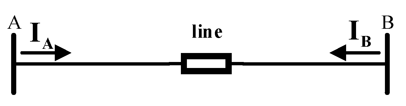
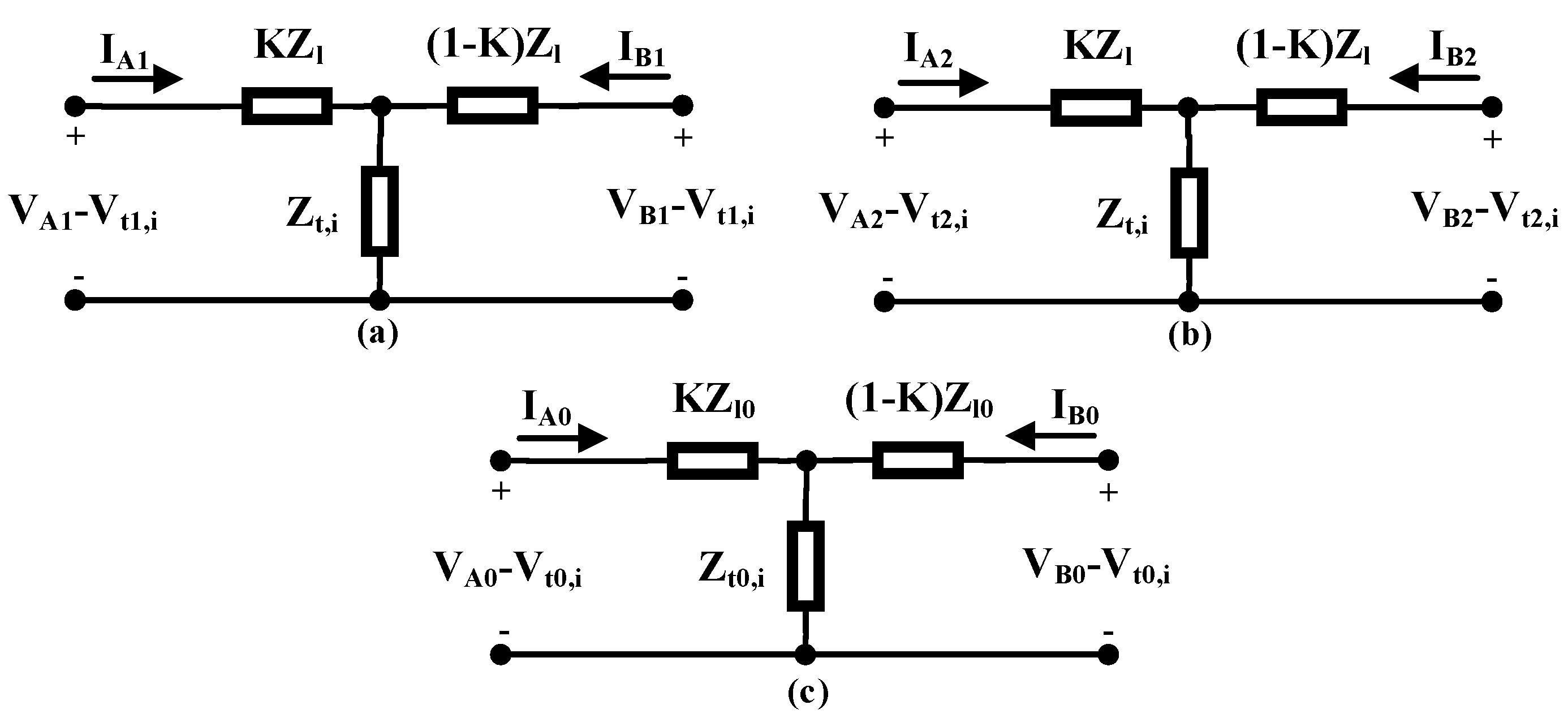
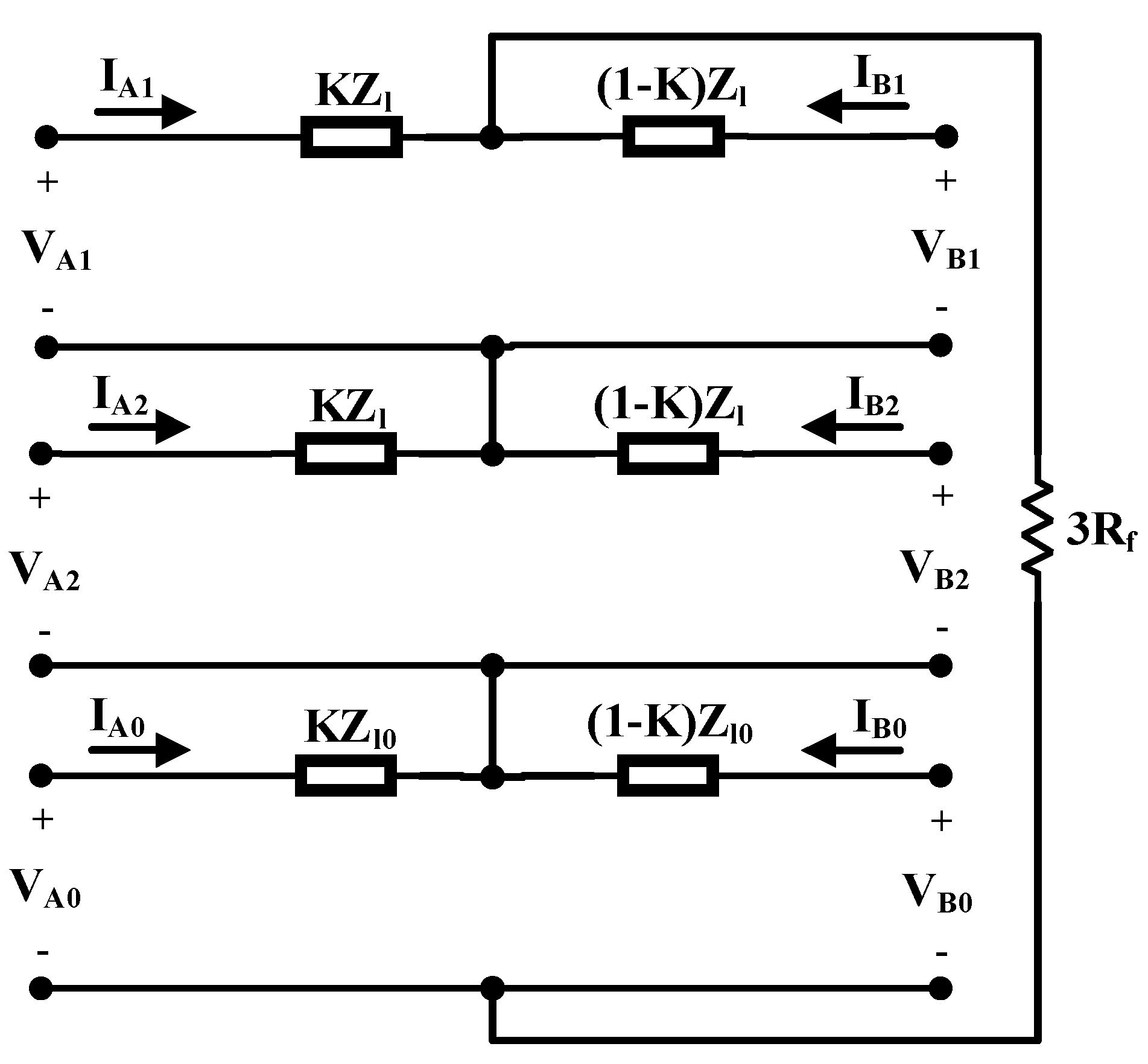
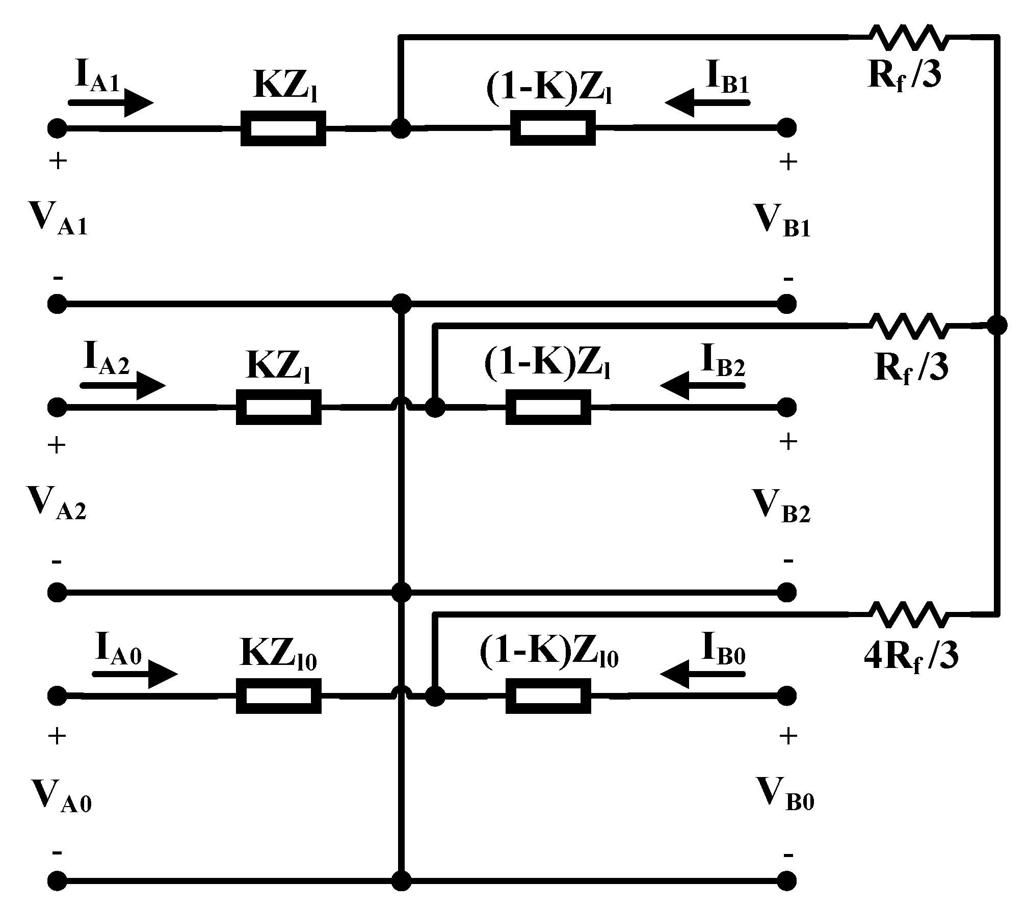
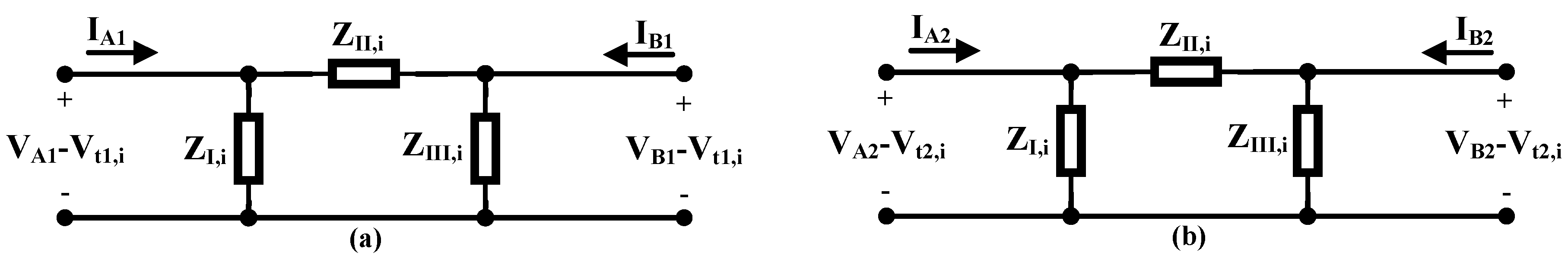
2. Modified Equivalent Circuits for Doubly-Fed Lines During Faults

In this section, an equivalent sequence circuit for doubly-fed distribution lines, shown in Figure 1, during short circuit faults has been discussed by using conventional equivalent sequence circuits.
In the following, simplified positive sequence (SPS), simplified negative sequence (SNS) and simplified zero sequence (SZS) equivalent circuits used in the proposed protection strategy are introduced. As shown in Figure 2, K represents fault location (0 < K < 1) and “i” is replaced by 3P (three-phase), LL (line-to-line), DLG (double-line-to-ground) and SLG (single line-to-ground) based on the fault type. Positive sequence by “1”, negative sequence by “2”, and zero sequence by “0” subscript will be indexed. Zl and Zl0 are positive and zero sequence line impedance respectively. Zt,i, Zt0,i, Vt1,n,Vt2,i and Vt0,i are sequence equivalent impedances and voltages that will be explained for fault types distinctively.

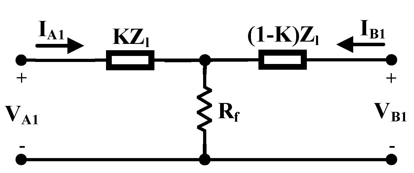
2.1. Three-Phase Faults

In this fault, three phases are connected to ground through resistance Rf. The equivalent circuit as shown in Figure 3 includes only the positive sequence.
Comparing Figure 3 and Figure 2, the SPS equivalent circuit for this type of fault is obtained:
Z t , 3 P = R f
V t 1 , 3 P = 0
Due to the absence of the negative and zero sequence components in this fault type, there are no SNS and SZS circuits.

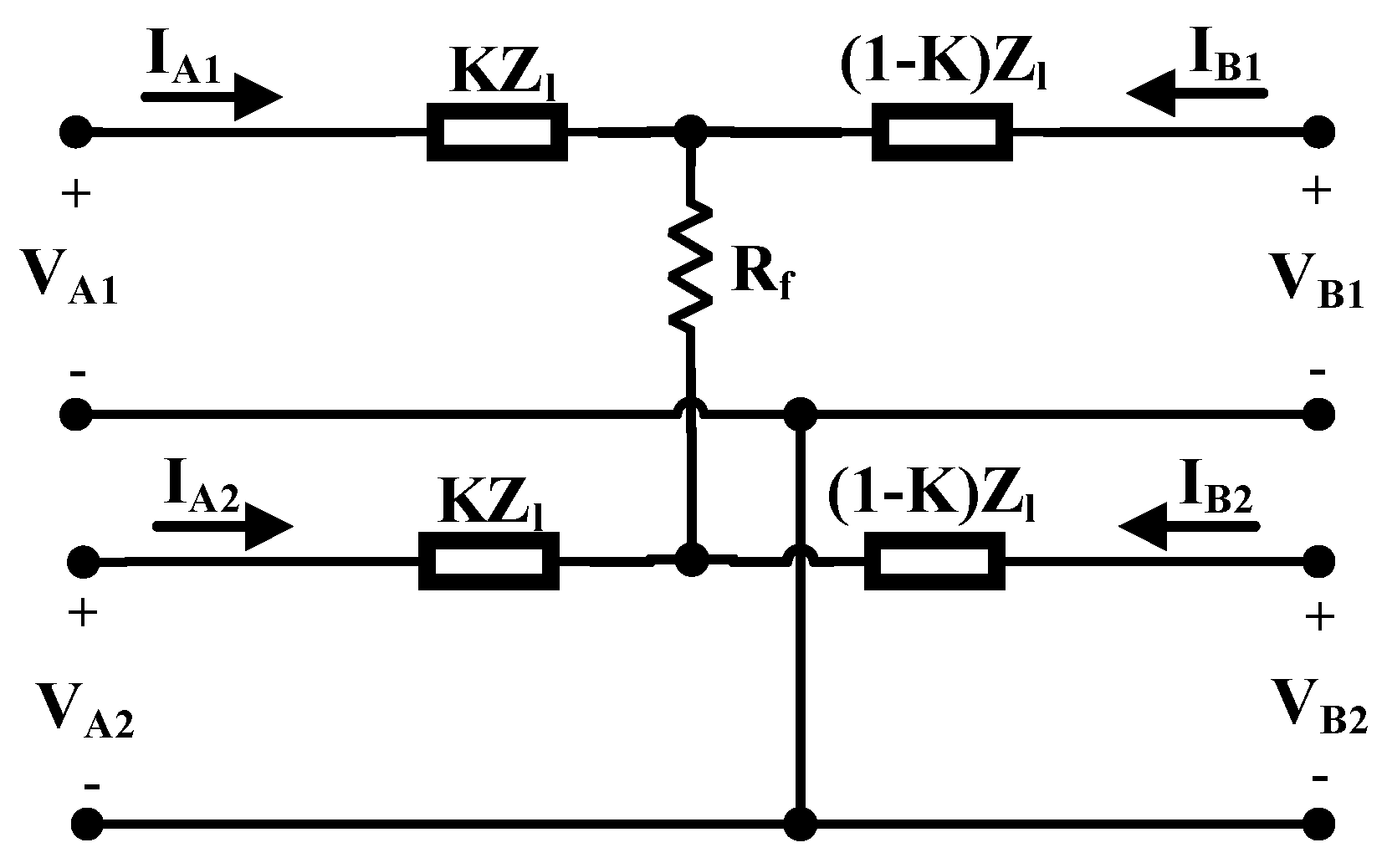
2.2. Line-to-Line Faults

In the line-to-line (LL) fault, two lines are connected through resistance Rf. The equivalent circuit contains positive and negative sequences as shown in Figure 4.
By maintaining the positive sequence circuit and converting the voltage VA2 series with KZl and the voltage VB2 series with (1-K)Zl to their corresponding dependent current sources parallel with the impedance, and then simplifying, the SPS equivalent circuit is obtained where Zt,LL and Vt1,LL are defined as follows:
Z t , L L = R f + K ( 1 K ) Z l
V t 1 , L L = ( 1 K ) V A 2 + K V B 2
Similarly, by maintaining the negative sequence circuit and simplifying, SNS circuit is obtained, in which:
V t 2 LL = ( 1 k ) V A 1 + K . V B 1
It should be mentioned that the SZS circuit does not exist in this fault type.

2.3. Single-Line-to-Ground Faults

Single-line-to-ground (SLG) fault occurs when one line is connected to the ground through resistance Rf. Figure 5 depicts the sequence equivalent circuits for this fault.
By maintaining the positive sequence circuit and simplifying two other sequence circuits, SPS is obtained and by the same way SNS and SZS are attained:
Z t , S L G = 3 R f + K ( 1 K ) ( Z l + Z l 0 )
V t 1 , S L G = ( 1 K ) ( V A 2 + V A 0 ) K ( V B 2 + V B 0 )
V t 2 , S L G = ( 1 K ) ( V A 1 + V A 0 ) K ( V B 1 + V B 0 )
Z t 0 , S L G = 3 R f + 2 K ( 1 K ) Z l
V t 0 , S L G = ( 1 K ) ( V A 1 + V A 2 ) K ( V B 1 + V B 2 )

2.4. Double-Line-to-Ground Faults

Double-line-to-ground (DLG) fault takes place when two lines are connected through resistance Rf and every line is connected through this resistance to the ground. Figure 6 shows sequence equivalent circuits for this fault.
Zt,DLG, Vt1,DLG and Vt2,DLG will be determined based on the SNS and SPS equivalent circuits as follows:
Z t , D L G = R f 3 + ( 3 K ( 1 K ) Z l 0 + 4 R f ) ( 3 K ( 1 K ) Z l + R f ) 3 ( 3 K ( 1 K ) ( Z l + Z l 0 ) + 5 R f )
V t 1 , D L G = M ( ( 1 K ) V A 2 + K V B 2 ) + N ( ( 1 K ) V A 0 + K V B 0 )
V t 2 , D L G = M ( ( 1 K ) V A 1 + K V B 1 ) + N ( ( 1 K ) V A 0 + K V B 0 )
where M and N are defined as follows:
M = 3 K ( 1 K ) Z l 0 + 4 R f 3 K ( 1 K ) ( Z l + Z l 0 ) + 5 R f
N = 3 K ( 1 K ) Z l + R f 3 K ( 1 K ) ( Z l + Z l 0 ) + 5 R f
Similarly SZS circuit is achieved in which:
Z t 0 , D L G = K ( 1 K ) Z l + 3 R f 2
V t 0 , D L G = ( 1 K ) 2 ( V A 1 + V A 2 ) + K 2 ( V B 1 + V B 2 )

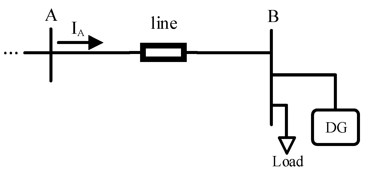
3. Proposed Protection Scheme for Distribution Lines

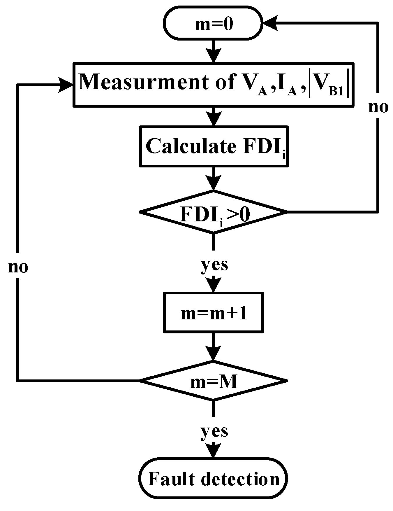
3.1. Main Protection Scheme

In the previous section, SPS, SNS and SZS equivalent circuits were obtained for the fault types. UsingY-Δ transform, SPS and SNS circuits can be redesigned as Figure 7, as followed:
Z I , i = K Z l + Z t , i 1 K
Z I I , i = Z l + K ( 1 K ) Z l 2 Z t , i
Z I I I , i = ( 1 K ) . Z l + Z t , i K
Figure 8 and Figure 9 show Rf-ZI,LL and Rf-ZII,LL curves for LL fault in several fault locations. According to Figure 8, the magnitude of ZI,LL increases by increasing Rf, therefore in normal conditions where Rf is infinite, ZI,LL is infinite and its angle is zero, But when a fault occurs, its magnitude decreases drastically and its angle increases up to positive sequence line impedance angle for Rf=0. Moreover, Figure 9 shows the magnitude and angle of ZII,LL will be equal to the positive sequence line impedance, in normal conditions. However during faults, its angle variations are low. Moreover, its magnitude variation is low, except in small Rf.
These facts are true for other fault types. The proposed fault detection scheme is based on high reduction in ZI,i during the fault, compared to normal conditions.
By applying KCL and KVL in SZS and Figure 7 circuits, (21)–(23) are obtained. In these equations Vt1,i, Vt2,i and Vt0,i are functions of K, Rf, the sequence voltages in the line ends and the sequence line impedances. Moreover, K and Rf are substituted by ZI,i and ZII,I according to (18) and (19). Obviously, some of these equations will not be used due to the absence of zero or negative sequences for some fault types.
I A 1 = V A 1 V B 1 Z I I , n + V A 1 V t 1 , n Z I , n
I A 2 = V A 2 V B 2 Z I I , n + V A 2 V t 2 , n Z I , n
V A 0 V t 0 , n K . Z l 0 . I A 0 Z t 0 , n . ( I A 0 + V B 0 V A 0 + K . Z l 0 . I A 0 ( 1 K ) . Z l 0 ) = 0
As stated earlier, in normal conditions, ZI,i tends to be a real large number. If the absolute value of VB1 is extracted from (21)–(23) and equals with its value sent from end B, and ZII,i is replaced by its normal condition value (Zl), an equation will be obtained in terms of ZI,i. By assuming ZI,i as a real number (as in normal conditions), two values can be obtained for ZI,i. one is negative that is ineligible and the other is infinite in normal conditions, and limited and positive during the fault. It is clear that during the fault, ZII,i is not exactly equal to Zl, So calculated ZI,I will include some errors. These can be ignored because, in normal conditions, ZI,i is infinite and it is greatly reduced when a fault with limited resistance occurs. So, some errors for this value during the fault, it is acceptable.
The Fault Detection Index (FDIi) is defined as follows:
F D I i = log ( C i Z I , i )
where Ci is a constant coefficient and considered a little greater than ZI,i in high impedance fault near the end B.
In normal conditions FDIi is negative. It may become positive transiently for external faults. Hence, positive FDIi for consecutive M samples shall indicate fault occurrence.
Therefore, in order to command the switches of terminal A, data including sequence voltages and currents of terminal A and the absolute value of the positive sequence voltage of terminal B are required. Sending minimum data from the other side of the line (only one parameter) reduces the amount of transmitted data. However, in the protection schemes so far, such as [27] it is usually necessary to send at least two parameters (magnitude and angle). So, data exchange reduces by 50% in the proposed scheme. Each line has two relays, one at the beginning and one at the end of the line. Therefore, in networks with a large number of lines, the data exchange volume will increase and this reduction is valuable. Moreover, the communication system may is used to exchange data in addition to the protection system data. Therefore, reducing the data exchange volume in the proposed protection system can make it possible to use the communication system in other applications.
The nonlinearity of the line parameters often affects transient state studies. In distribution lines, due to the resistance is large compared to the reactance, the transient state is damped quickly. Therefore, the non-linearity of the line parameters does not affect the proposed scheme, which uses phasor quantities. Moreover, leakage current due to insulators is very low and it does not affect the correct performance of the proposed scheme. However, because the proposed main protection scheme is capable to detect high resistance faults, if the leakage current increases due to pollution of insulators or their insulation problems, the scheme may detect it as a fault and command trip. The flowchart in Figure 10 explains this scheme.
The proposed main protection scheme can detect all types of faults, but the scheme presented in [27] only could detect single-phase to the ground and two-phase ones. Moreover, the scheme presented in [27] included 3 plans to detect low, medium, and high resistance fault, but the proposed scheme detects all fault by one plan.

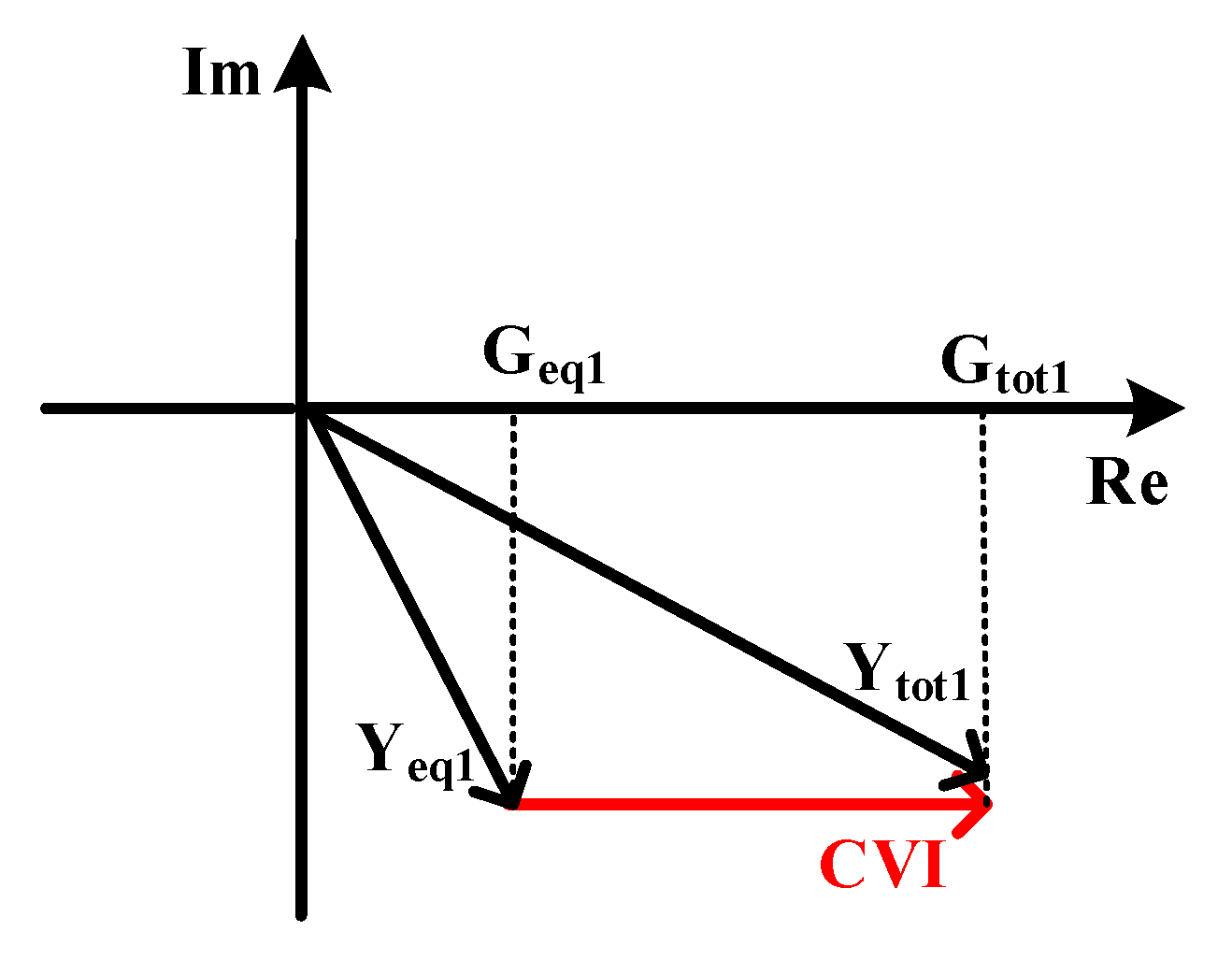
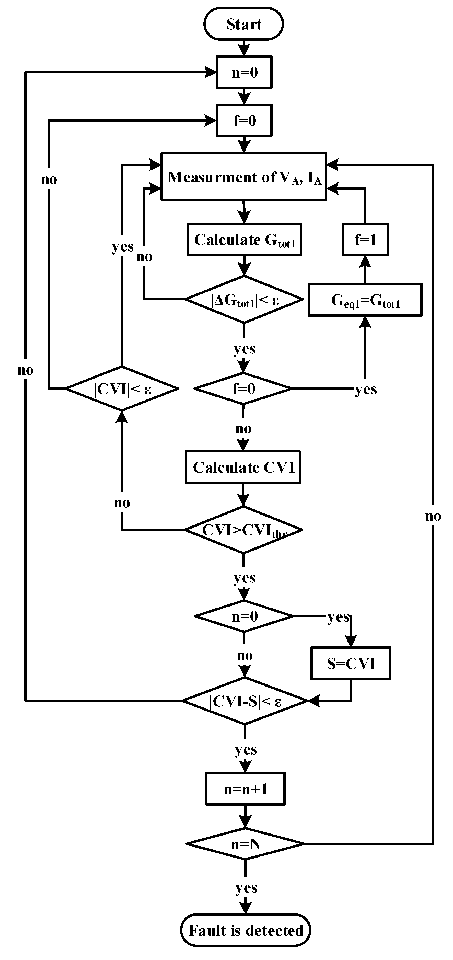
3.2. Backup Protection Scheme
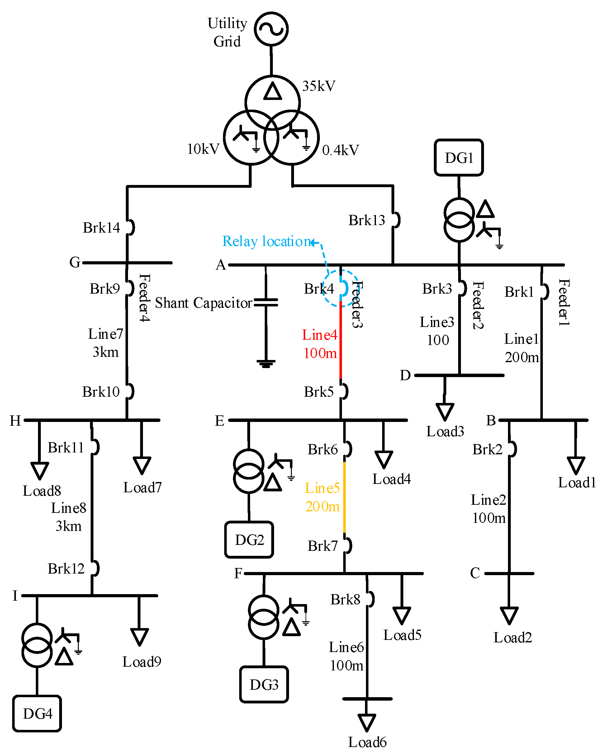
In [27], the reactance seen from the beginning of the line was applied for fault detection. Under normal conditions, the positive sequence impedance seen from the beginning of the line may be different depending on operation modes of the microgrid (grid-connected or islanded) and, transition direction of the active and reactive power in the line. These different pre-fault conditions affect the during the fault impedance seen from the beginning of the line, when the fault is not solid. Therefore, the scheme proposed in [27] performed well for very low fault resistance, but it seriously is challenged for fault resistance partial increasing.
In the distribution line in Figure 11, “DG” and “load” represent DGs total power and total load, in downstream of bus B, respectively. DG positive sequence admittance is YG1 and load positive sequence admittance is YD1. So, the equivalent positive sequence admittance Yeq1 is:
Y e q 1 = Y D 1 + Y G 1 = G e q 1 + j B e q 1
where, the real and imaginary parts of Yeq1 are named Geq1 and Beq1. Moreover, positive sequence admittance seen from bus A, represented by Ytot1 is considered:
Y t o t 1 = G t o t 1 + j B t o t 1
Gtot1 and Btot1 are real and imaginary part of Ytot1.
In normal conditions, ignoring line impedance, Ytot1 is equal to Yeq1, and according to Geq1 and Beq1 values, it may be at any point of the complex coordinate system.
If a fault with resistance Rf occurred at line AB, regardless of the line impedance and Yeq1 changes during the fault, Rf becomes parallel to Yeq1, so Ytot1 moves to the right at complex coordinate plane. By a lower Rf, admittance Ytot1 will move further to the right at complex coordinate plane. This conductance variation is defined as Conductance Variation Index (CVI) which is a basis for proposed fault detection scheme. CVI is shown in Figure 12 and obtained as follows:
C V I = G t o t 1 G e q 1
In normal conditions, CVI is zero, and it increases during faults. By setting an appropriate threshold for CVI, the fault will be detected. Threshold value should be set in order not to recognize connecting a large load as a fault by protection system. Therefore, considering Sload,max as maximum sudden load increase, the threshold value CVIthr is obtained as follows:
C V I t h r = S l o a d , max V L L , r a t e d 2
where VLL,rated is rated line to line voltage of the network.
In grid-connected mode, DGs inject constant powers and their output powers do not change as the load increases, so Yeq1 remains constant. However in islanded mode, as the network load increases, the power outputs of the DGs increase for supplying the added load. So, if Yeq1 is at the left half of the complex coordinate plane, the absolute value of Yeq1 increases, and it moves to the left at the complex plane, so there is not possible to detect load adding as a fault. Moreover, if Yeq1 is at the right half of the complex plane, the absolute value of Yeq1 decreases, and it moves to the left at the complex plane, accordingly, mal-operation of backup protection system shall be impossible, too
So, by changing the load downstream of the relay, CVI varies but it does not exceed its threshold. In this situation, Geq1 should be updated to Gtot1 for the next calculations. Moreover, if the fault is tripped by main protection, before backup protection operation, then Geq1 should be updated. The flowchart of this scheme is described in Figure 13. In this flowchart, ε represents the measurement error, and ΔGtot1 is the difference between the value of Gtot1 and its value in the previous sample. N is the number of samples during which the backup protection is waiting for the main protection operation.
It is notable that in high resistance faults, CVI may don’t reach its threshold or DGs controllers may be able to compensate for the impedance changes due to the fault, so, CVI will not be able to detect high resistance faults, but, compared to the scheme proposed in [27], it performs better in presence fault resistance. Moreover, the elimination of the communication link is a great advantage of this scheme and makes it appropriate for backup protection. Moreover, because of Geq1 updating, this scheme is robust against network reconfigurations.

4. Case Study

To evaluate the proposed scheme, an active distribution network 50 Hz in Figure 14 was simulated in PSCAD and calculated in MATLAB [27]. The network consists of two 0.4 kV and 10 kV subnets connected to the 35 kV main network through a transformer. The fault level in the coupling point with the utility is 500 MVA and R/X ratio is 0.1. DG1 is a battery-energy-storage system (BESS) with a nominal power of 200 kVA, DG2 is a 100 kVA combined cool, heat, and power (CCHP) and DG3 is a photovoltaic cell with a nominal power of 50 kVA. Positive and negative sequence resistance and inductance of 0.4 kV lines are 0.32 Ω/km and 0.261 mH/km, and zero sequence ones are 1.1 Ω/km and 0.955 mH/km. The loads 1 to 6 powers are 40 kVA, 20 kVA, 40 kVA, 40 kVA, 5 kVA and 25 kVA with power factor 0.9 lag, respectively. The shunt capacitor is 20 kVAr.
The positive sequence resistance and inductance of the 10 kV feeder are 0.38 Ω/km and 1.432 mH/km, respectively and zero sequence ones are 0.76 Ω/km and 4.2 mH/km. There is a 600 kVA diesel generator (DG4) at the end of this feeder. The loads 7 to 9 powers are 100 kVA, 500 kVA and 500 kVA with power factor 0.85 lag, respectively.
The low-voltage subsystem can form a microgrid, continuing to energize 0.4 kV feeders during islanded mode operation. The control of BESS or CCHP switches from P-Q to v-f for supporting voltage and frequency but because of PV system nature, it maintains P-Q control regardless of grid-connected or islanded mode operation. Moreover, the output current of DG during fault conditions is limited to 1.5(1 and half) times of rated current.

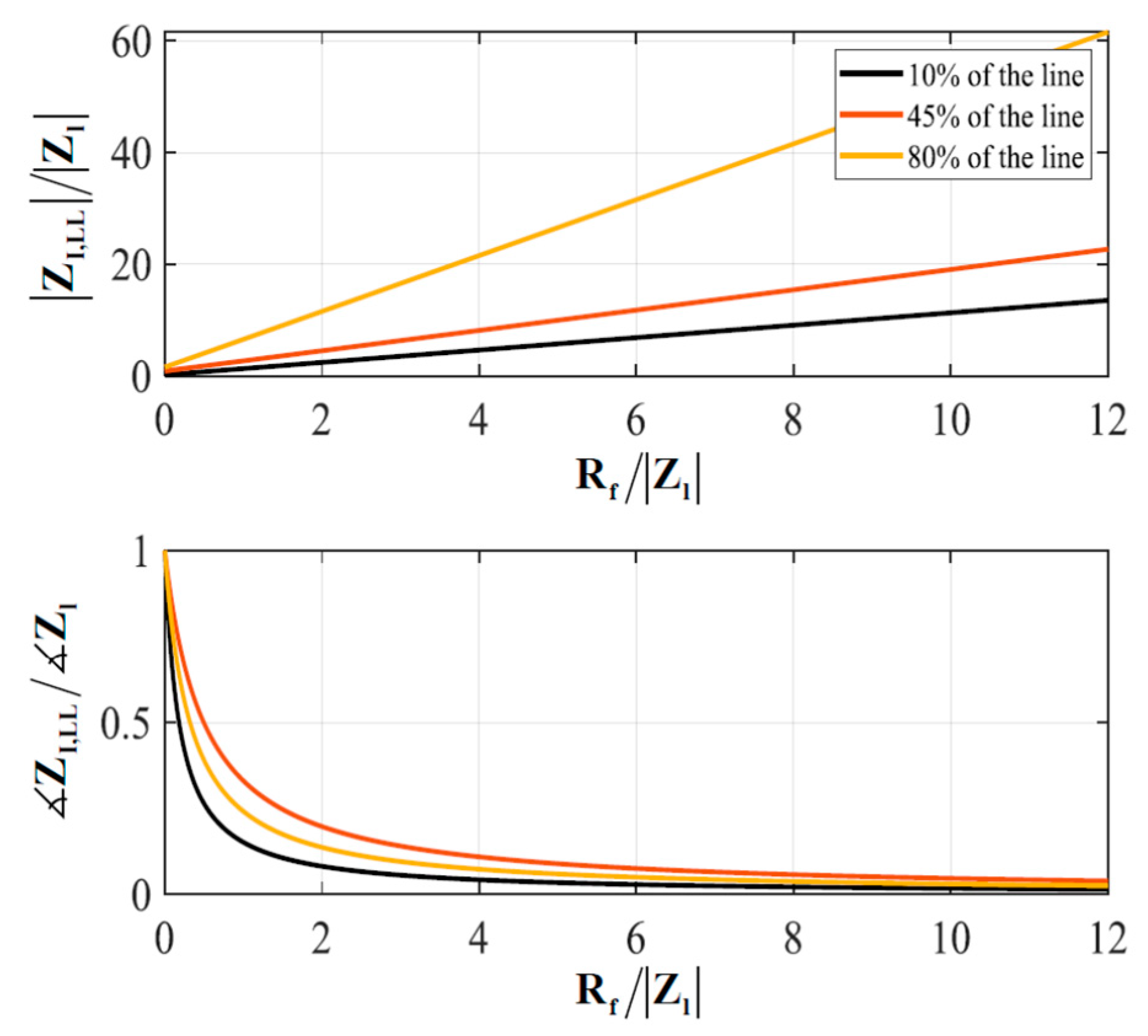
5. Evaluation of the Proposed Protection Schemes

In this case study, protection of line 4 is more difficult compared to others, because it is connected to the main grid and DG1 in upstream, and DG2 and DG3 downstream. In the islanded mode, DG2 operates in v-f control and DG3 in P-Q control. So, if the proposed schemes protect line 4 accurately, it will protect other lines properly.

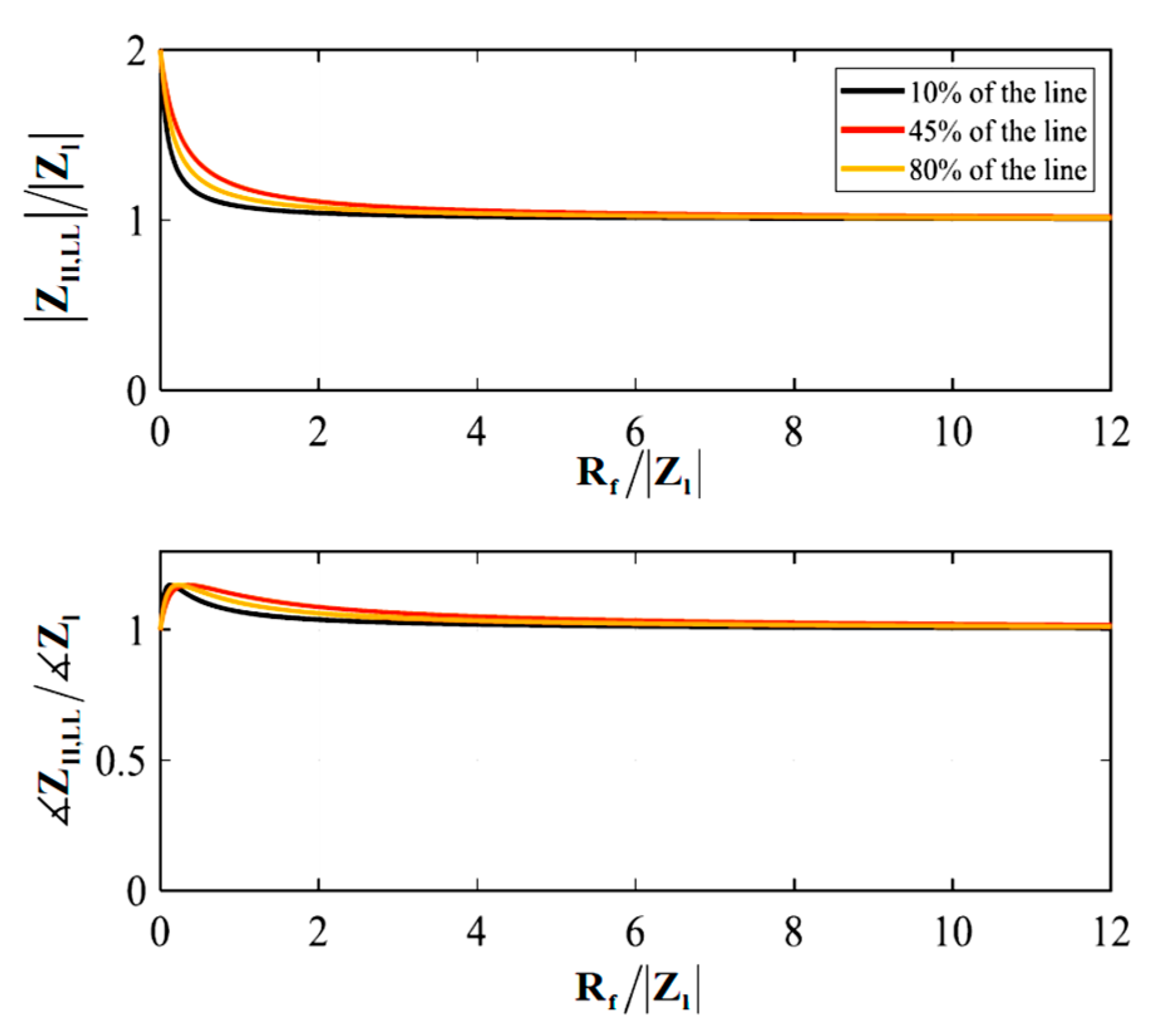
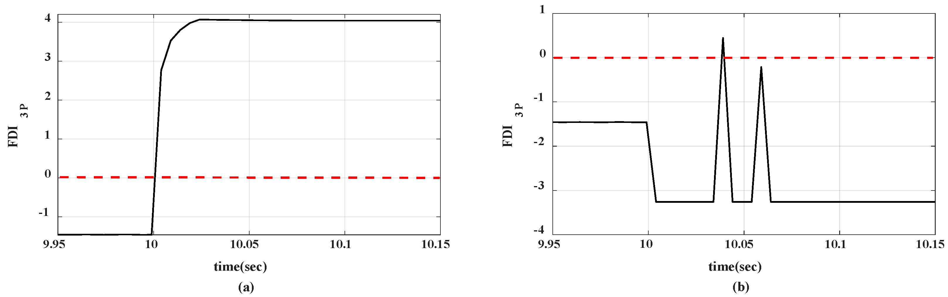
5.1. Main Protection Scheme Evaluation

To evaluate the proposed protection scheme, different faults with different fault resistances at line 4 were studied. Moreover, faults at lines 3 and 5 are investigated for its performance in external faults. The fault occurs at t = 10 s and the sampling frequency is 200 Hz.
Ci should be set in order to be positive for the highest intended fault resistance at the end of the line. Therefore considering faults at 90% of line 4 and fault resistance 50 ohm, C3P, CDLG, CLL, and CSLG were obtained 550, 330, 550, and 1640 respectively.
Figure 15 shows FDI3P curve for a three-phase fault with a fault resistance 0.01 ohm at 50% of line 4 and 10% of line 5 in the grid-connected mode. When a fault happens at line 4, FDI3P raises quickly and remains positive. However, when a fault occurs at 10% of line 5, FDI3P increases transiently and droops rapidly. Considering all fault types with different resistances at different locations, M (number of samples in which FDIi should remain positive) was equal to 6.
Table 1, Table 2, Table 3 and Table 4 show FDIi values of the relay at beginning of line 4 after 6 consecutive positive samples, and response time of the proposed scheme for fault resistance 0.01 to 50 ohm. For the faults at line 4, FDIi was positive constantly, and trip command was generated after 6 consecutive positive samples for Brk4 to disconnect the faulty line. Moreover, for external faults (in adjacent lines), FDIi remains negative or becomes transiently positive, and then the trip command is not generated. Similarly, this scheme can be implemented for the relay at the end of line 4 to command Brk5. Therefore, Brk4 and Brk5 disconnect the faulty line.
Unlike the transmission lines, because of a short distance between data sending and receiving points, in distribution lines noise presence in transmitted data is rare, and usually, it is not investigated. Moreover, due to short lines in distribution networks, fault location determination is not applicable.
Normally, in the short circuit faults investigations, the pre-fault line currents are ignored because the fault current is high. However, for high impedance faults, it is not high compared to the loads currents, and may affect the performance of the protection system. So, In order to investigate the effect of loads and DGs currents on the performance of the proposed high impedance faults detection scheme, another pre-fault condition was considered. In this case, loads in the microgrid, i.e., loads 1 to 6, were considered doubled and DG 3 was off. Moreover, to investigate the fault inception angle effect, the initiation time of fault was considered 10.005 s (fault inception angle was π 2 rad).
The results in Table 5 show the correct performance of the proposed scheme in the new pre-fault conditions. So, this scheme is robust against loads and generation uncertainties, and fault inception angle variations.
In order to evaluate the performance of the proposed scheme in transient situations due to load changes, a 30 kVA load was added to the bus E att = 10 s. According to corresponding FDI3P curves in Figure 16, connecting this load did not make a permanent positive FDI3P, and the performance of the protection system was not challenged.
Therefore, the proposed scheme can detect all fault types correctly in grid-connected and islanded modes. Moreover, the results show its response time is 30 to 50 ms, which its average is 32.8 ms. This indicates the operation of the proposed main scheme is almost 34% faster than other ones such as [27]. Moreover, the low sampling rate (200 Hz) is one advantage of this scheme.

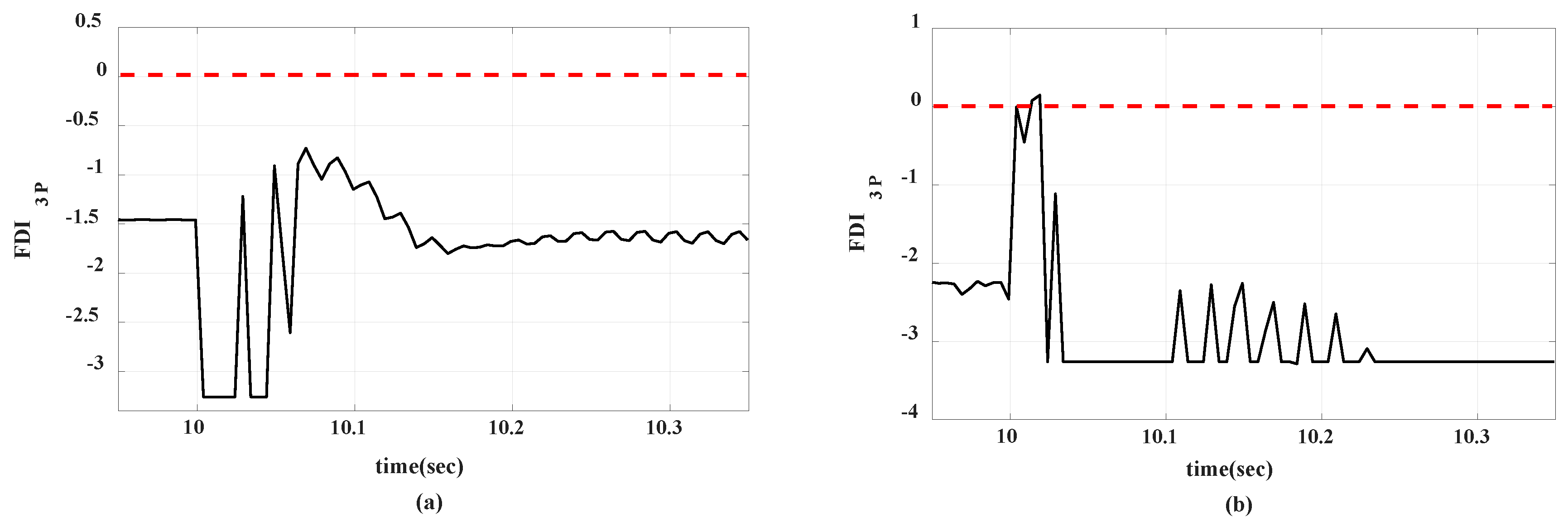
5.2. Backup Protection Scheme Evaluation

Since, for the faults with resistance, the pre-fault conditions affect during the fault impedance, fault types at lines 4 and 5 with fault resistance 2 ohm have been studied in several pre-fault conditions in order to evaluate the backup protection scheme. The conductance seen from bus A has been measured. The pre-fault conditions were considered as follows:
The maximum sudden load change in the low voltage distributed network was assumed 30 KVA with power factor 0.9 lag. Considering this load change, CVIthr was obtained 0.1875.
If a fault occurs at lines 4 or 5 and their relays fail to recognize fault within 50 ms in their main zones, the relay at the beginning of line 4 will detect the fault in the backup zone and will command a trip. However, if relays detect the fault in the main zones and command a trip, the relay at the beginning of line 4 will see another change after the first one in a time shorter than 50 ms and will be reset. So, N must be greater than M, therefore, it was considered 40 equivalent to 200 ms, which is the normal response time for backup schemes. The performance of the proposed backup protection scheme and the reactance-based one explained in [27], have been compared in Table 6, Table 7, Table 8 and Table 9. Results showed that different pre-fault conditions did not affect the accurate performance of the proposed backup scheme. This scheme could detect fault types downstream of the relay in both grid-connected and islanded modes and did not command trip for the fault at upstream of the relay (at line 3) and adding load 30 kVA at the end of line 5. According to these results, the reactance-based scheme in [27] performed correctly for 60% and, the proposed scheme detected faults for 100% of cases.
(a)
Loads and DGs properties were considered similar to Section 4.
(b)
Loads powers in the microgrid were doubled compared to condition “a”.
(c)
Loads powers in the microgrid were halved compared to condition “a”.
(d)
Loads powers were similar to condition “a” but DG2 and DG3 were disconnected.

6. Conclusions

Despite microgrids’ numerous advantages, their development and extension in distribution networks have made serious challenges for network protection systems, and fault detection is challenged by traditional methods.
In this article, by reconfiguring sequence equivalent circuits for the faults types in distribution and transmission lines, new equivalent circuits for positive, negative, and zero sequences are presented. These circuits are called simplified positive sequence (SPS), simplified negative sequence (SNS), and simplified zero sequence (SZS) circuits. Then, by applying star to delta transform, the proposed circuits are converted to equivalent delta ones. The impedances in these circuits were estimated approximately using the voltages and currents measured at the ends of the line. The Significant change in one of these impedances during the faults is the basis of the proposed main protection scheme for the active distribution lines in microgrids. In this scheme, indexFDI is proposed for faults detection in both grid-connected and islanded modes, and because it is based on impedance, fault level changes due to the microgrid operation modes (islanded and grid-connected) or loads changes, do not affect its performance. Its average response time shows its fast performance. Voltage and current at beginning of the line and absolute value of positive sequence voltage send from the end of the line are used in this scheme. Therefore, at least 50% of the communication system is released. High impedance faults detection capability and low sampling rate are among the advantages of the proposed scheme. Robustness against network reconfigurations, correct performance in presence of infeed, transient situations, and load and generation uncertainties are capabilities of the proposed scheme.
Also, CVI based on the conductance variation has been proposed for downstream lines backup protection in grid-connected and islanded modes. No requirement to any communication link is a distinguished advantage of this scheme, so if the communication link is disconnected or the main protection is failed, it will be capable to protect the network. Moreover, it is independent of pre-fault conditions.
The proposed schemes have been simulated using PSCAD and MATLAB software and the results have confirmed their accuracy.

Author Contributions

Conceptualization, S.M.N. and A.K.; Methodology, S.M.N. and A.K.; Software, S.M.N.; Validation, S.M.N. and A.K.; Supervision, A.K.; Writing—original draft preparation S.M.N.; Writing—review & editing, A.K., M.S.-k. All authors have read and agreed to the published version of the manuscript.

Funding

Not applicable.

Institutional Review Board Statement

Not applicable.

Informed Consent Statement

Not applicable.

Data Availability Statement

All data are given in the paper. Separately there is no other data.

Acknowledgments

Miadreza Shafie-khah acknowledges the support by the Business Finland through SolarX Research Project, 2019–2021, under Grant 6844/31/2018.

Conflicts of Interest

The authors declare no conflict of interest.

References

  1. Mirsaeidi, S.; Said, D.M.; Mustafa, M.W.; Habibuddin, M.H.; Ghaffari, K. Modeling and simulation of a communication-assisted digital protection scheme for micro-grids. Renew. Sustain. Energy Rev. 2016, 57, 867–878. [Google Scholar] [CrossRef]
  2. Teimourzadeh, S.; Aminifar, F.; Davarpanah, M.; Guerrero, J.M. Macroprotections for Microgrids: Toward a New Protection Paradigm Subsequent to Distributed Energy Resource Integration. IEEE Ind. Electron. Mag. 2016, 10, 6–18. [Google Scholar] [CrossRef] [Green Version]
  3. Blaabjerg, F.; Yang, Y.; Yang, D.; Wang, X. Distributed Power-Generation Systems and Protection. Proc. IEEE 2017, 105, 1311–1331. [Google Scholar] [CrossRef] [Green Version]
  4. Jiao, Z.; Jin, J.; Liu, L.; Wang, Y.; Wang, Q.; Wang, Z. A Practical Setting Method for Over-Current Relay and Automatic Recloser in Distribution Network with Photovoltaic Station. Int. J. Electr. Energy. 2015, 3, 225–229. [Google Scholar] [CrossRef] [Green Version]
  5. Adly, A.R.; El-Sehiemy, R.A.; Abdelaziz, A.Y. Optimal reclosing time to improve transient stability in distribution system. CIRED-Open Access Proc. J. 2017, 2017, 1359–1362. [Google Scholar] [CrossRef]
  6. Aminifar, F.; Fotuhi-Firuzabad, M.; Safdarian, A.; Davoudi, A.; Shahidehpour, M. Synchrophasor Measurement Technology in Power Systems: Panorama and State-of-the-Art. IEEE Access 2014, 2, 1607–1628. [Google Scholar] [CrossRef]
  7. Ghanbari, T.; Farjah, E. Unidirectional Fault Current Limiter: An Efficient Interface Between the Microgrid and Main Network. IEEE Trans. Power Syst. 2013, 28, 1591–1598. [Google Scholar] [CrossRef]
  8. Khederzadeh, M. Preservation of over current relays coordination in microgrids by application of static series compensators. In Proceedings of the 11th Int. Conference on Developments in Power Systems Protection (DPSP), Birmingham, UK, 23–25 April 2012; pp. 1–6. [Google Scholar]
  9. Dahej, A.E.E.; Esmaeili, S.; Hojabri, H. Co-Optimization of Protection Coordination and Power Quality in Microgrids Using Unidirectional Fault Current Limiters. IEEE Trans. Smart Grid. 2017, 9, 5080–5091. [Google Scholar] [CrossRef]
  10. Oureilidis, K.O.; Demoulias, C.S. A Fault clearing method in converter-dominated microgrids with conventional protection means. IEEE Trans. Power Electron. 2016, 31, 4628–4640. [Google Scholar] [CrossRef]
  11. Orji, U.; Schantz, C.; Leeb, S.B.; Kirtley, J.L.; Sievenpiper, B.; Gerhard, K.; McCoy, T. Adaptive Zonal Protection for Ring Microgrids. IEEE Trans. Smart Grid. 2015, 8, 1843–1851. [Google Scholar] [CrossRef]
  12. Khederzadeh, M. Adaptive setting of protective relays in microgrids in grid-connected and autonomous operation. In Proceedings of the 11th Int. Conference on Developments in Power Systems Protection (DPSP), Birmingham, UK, 23–25 April 2012; pp. 14–20. [Google Scholar]
  13. Laaksonen, H.; Ishchenko, D.; Oudalov, A. Adaptive protection and microgrid control design for Hailuoto island. IEEE Trans. Smart Grid. 2014, 5, 1486–1493. [Google Scholar] [CrossRef]
  14. Zeineldin, H.H.; El-Saadany, E.F.; Salama, M.M.A. Distributed Generation Micro-Grid Operation: Control and Protection. In Proceedings of the 2006 Power Systems Conference: Advanced Metering, Protection, Control, Communication, and Distributed Resources, Atlanta, GA, USA, 29 October–1 November 2006; pp. 105–111. [Google Scholar]
  15. Sortomme, E.; Venkata, S.S.; Mitra, J. Microgrid Protection Using Communication-Assisted Digital Relays. IEEE Trans. Power Deliv. 2010, 25, 2789–2796. [Google Scholar] [CrossRef]
  16. Aghdam, T.S.; Karegar, H.K.; Zeineldin, H. Variable Tripping Time Differential Protection for Microgrids Considering DG Stability. IEEE Trans. Smart Grid. 2019, 10, 2407–2415. [Google Scholar] [CrossRef]
  17. Kar, S.; Samantaray, S.R.; Zadeh, M.D. Data-Mining Model Based Intelligent Differential Microgrid Protection Scheme. IEEE Syst. J. 2015, 11, 1161–1169. [Google Scholar] [CrossRef]
  18. Loix, T.; Wijnhoven, T.; Deconinck, G. Protection of microgrids with a high penetration of inverter-coupled energy sources. In Proceedings of the CIGRE/IEEE PES Joint Symposium Integration of Wide-Scale Renewable Resources Into the Power Delivery System, Calgary, AB, Canada, 29–31 July 2009; pp. 1–8. [Google Scholar]
  19. Sharma, N.K.; Samantaray, S.R. Assessment of PMU-based wide-area angle criterion for fault detection in microgrid. IET Gener. Transm. Distrib. 2019, 13, 4301–4310. [Google Scholar] [CrossRef]
  20. Best, R.J.; Morrow, D.J.; Crossley, P.A. Communication assisted protection selectivity for reconfigurable and islanded power networks. In Proceedings of the 44th Int. Universities Power Engineering Conf. (UPEC), Glasgow, UK, 1–4 September 2009; pp. 1–4. [Google Scholar]
  21. Darabi, A.; Bagheri, M.; Gharehpetian, G.B. Highly sensitive microgrid protection using overcurrent relays with a novel relay characteristic. IET Renew. Power Gener. 2020, 14, 1201–1209. [Google Scholar] [CrossRef]
  22. Zamani, M.A.; Sidhu, T.S.; Yazdani, A. A Protection Strategy and Microprocessor-Based Relay for Low-Voltage Microgrids. IEEE Trans. Power Deliv. 2011, 26, 1873–1883. [Google Scholar] [CrossRef]
  23. Furlan, R.H.; Beuter, C.H.; Bataglioli, R.P.; Faria, I.D.M.; Oleskovicz, M. Improvement of overcurrent protection considering distribution systems with distributed generation. In Proceedings of the 2018 18th International Conference on Harmonics and Quality of Power (ICHQP), Ljubljana, Slovenia, 13–16 May 2018; pp. 1–5. [Google Scholar]
  24. Hooshyar, A.; Iravani, R. Microgrid Protection. Proc. IEEE 2017, 105, 1332–1353. [Google Scholar] [CrossRef]
  25. Nikolaidis, V.C.; Tsimtsios, A.M.; Safigianni, A.S. Investigating Particularities of Infeed and Fault Resistance Effect on Distance Relays Protecting Radial Distribution Feeders With DG. IEEE Access 2018, 6, 11301–11312. [Google Scholar] [CrossRef]
  26. Bottrell, N.; Green, T.C. An impedance-based method for the detection of over-load and network faults in inverter interfaced distributed generation. In Proceedings of the 2013 15th European Conference on Power Electronics and Applications (EPE), Lille, France, 3–5 September 2013; pp. 1–10. [Google Scholar]
  27. Huang, W.; Nengling, T.; Zheng, X.; Fan, C.; Yang, X.; Kirby, B.J. An Impedance Protection Scheme for Feeders of Active Distribution Networks. IEEE Trans. Power Deliv. 2014, 29, 1591–1602. [Google Scholar] [CrossRef]
  28. Pandakov, K.; Hidalen, H.K. Distance protection with fault impedance compensation for distribution network with DG. In Proceedings of the IEEE PES Innovative Smart Grid Technologies Conf. Europe (ISGT-Europe), Torino, Italy, 26–29 September 2017. [Google Scholar]
  29. Biller, M.; Jaeger, J. Voltage-Free Distance Protection Method for Closed Loop Structures. In Proceedings of the 2018 IEEE PES Innovative Smart Grid Technologies Conference Europe (ISGT-Europe), Sarajevo, Bosnia and Herzegovina, 21–25 October 2018; pp. 1–6. [Google Scholar]
  30. Fang, Y.; Jia, K.; Yang, Z.; Li, Y.; Bi, T. Impact of Inverter-Interfaced Renewable Energy Generators on Distance Protection and an Improved Scheme. IEEE Trans. Ind. Electron. 2018, 66, 7078–7088. [Google Scholar] [CrossRef]
Figure 1. Doubly-fed line.
Energies 14 00274 g001
Figure 2. (a) SPS circuit; (b) SNS circuit; (c) SZS circuit.
Energies 14 00274 g002
Figure 3. SPS equivalent circuit for 3P fault.
Energies 14 00274 g003
Figure 4. Sequence equivalent circuits for LL fault.
Energies 14 00274 g004
Figure 5. Sequence equivalent circuits for SLG fault.
Energies 14 00274 g005
Figure 6. Sequence equivalent circuits for DLG fault.
Energies 14 00274 g006
Figure 7. Transformed (a) SPS and (b) SNS circuit to equivalent delta.
Energies 14 00274 g007
Figure 8. Rf-ZI,LL curve for several fault location.
Energies 14 00274 g008
Figure 9. Rf-ZII,LL curve for several fault location.
Energies 14 00274 g009
Figure 10. Flowchart of the proposed main protection scheme.
Energies 14 00274 g010
Figure 11. Network with lumped downstream.
Energies 14 00274 g011
Figure 12. Definition of CVI.
Energies 14 00274 g012
Figure 13. Flowchart of backup protection scheme.
Energies 14 00274 g013
Figure 14. Case study system.
Energies 14 00274 g014
Figure 15. FDI3P for three-phase fault with resistance 0.01 ohm in grid-connected mode at (a) 50% of line 4 (permanently positive) (b) 10% of line 5 (transiently positive).
Energies 14 00274 g015
Figure 16. FDI3P for load change at bus E in (a) grid-connected mode (negative) (b) islanded mode (transiently positive).
Energies 14 00274 g016
Table 1. Performance of the proposed main scheme in 3P faults.
Operation ModeFault Type- Fault Res.Fault LocationInside the Prot. ZoneFDI3PCorrect Perf. Resp. Time (ms).
Grid-connected3P-0.01Ω10% of Line 4Yes3.9430
50% of Line 4Yes4.0630
90% of Line 4Yes3.2135
10% of Line 3NoTP-
10% of Line 5NoTP-
3P-1Ω10% of Line 4Yes2.6930
50% of Line 4Yes2.4330
90% of Line 4Yes1.7230
3P-10Ω10% of Line 4Yes1.730
50% of Line 4Yes1.4430
90% of Line 4Yes0.7435
3P-50Ω10% of Line 4Yes130
50% of Line 4Yes0.7535
90% of Line 4Yes0.0550
Islanded3P-0.01Ω10% of Line 4Yes4.6330
50% of Line 4Yes4.2130
90% of Line 4Yes3.4630
10% of Line 3NoTP-
10% of Line 5NoTP-
3P-1Ω10% of Line 4Yes2.6930
50% of Line 4Yes2.4430
90% of Line 4Yes1.7330
3P-10Ω10% of Line 4Yes1.6930
50% of Line 4Yes1.4430
90% of Line 4Yes0.7430
3P-50Ω10% of Line 4Yes130
50% of Line 4Yes0.7435
90% of Line 4Yes0.0445
TP: Transiently positive.
Table 2. Performance of proposed main scheme in DLG faults.
Operation ModeFault Type- Fault Res.Fault LocationInside the Prot. ZoneFDIDLGCorrect Perf.Resp. Time (ms).
Grid-connectedDLG-0.01Ω10% of Line 4Yes3.7530
50% of Line 4Yes3.730
90% of Line 4Yes2.7940
10% of Line 3NoTP-
10% of Line 5NoNegative-
DLG-1Ω10% of Line 4Yes2.6930
50% of Line 4Yes2.4230
90% of Line 4Yes1.730
DLG-10Ω10% of Line 4Yes1.6930
50% of Line 4Yes1.4430
90% of Line 4Yes0.7440
DLG-50Ω10% of Line 4Yes130
50% of Line 4Yes0.7435
90% of Line 4Yes0.0550
IslandedDLG-0.01Ω10% of Line 4Yes4.4830
50% of Line 4Yes3.8530
90% of Line 4Yes2.9630
10% of Line 3NoTP-
10% of Line 5NoTP-
DLG-1Ω10% of Line 4Yes2.6930
50% of Line 4Yes2.4330
90% of Line 4Yes1.7230
DLG-10Ω10% of Line 4Yes1.6930
50% of Line 4Yes1.4430
90% of Line 4Yes0.7330
DLG-50Ω10% of Line 4Yes130
50% of Line 4Yes0.7430
90% of Line 4Yes0.0440
TP: Transiently positive.
Table 3. Performance of the proposed main scheme in LL faults.
Operation ModeFault Type- Fault Res.Fault LocationInside the Prot. ZoneFDILLCorrect Perf.Resp. Time (ms).
Grid-connectedLL-0.01Ω10% of Line 4Yes4.4730
50% of Line 4Yes3.8230
90% of Line 4Yes2.9240
10% of Line 3NoTP-
10% of Line 5NoNegative-
LL-1Ω10% of Line 4Yes2.6930
50% of Line 4Yes2.4330
90% of Line 4Yes1.7240
LL-10Ω10% of Line 4Yes1.6930
50% of Line 4Yes1.4430
90% of Line 4Yes0.7440
LL-50Ω10% of Line 4Yes130
50% of Line 4Yes0.7435
90% of Line 4Yes0.0550
IslandedLL-0.01Ω10% of Line 4Yes4.5430
50% of Line 4Yes3.9330
90% of Line 4Yes2.9930
10% of Line 3NoTP-
10% of Line 5NoTP-
LL-1Ω10% of Line 4Yes2.6930
50% of Line 4Yes2.4330
90% of Line 4Yes1.7230
LL-10Ω10% of Line 4Yes1.6930
50% of Line 4Yes1.4430
90% of Line 4Yes0.7430
LL-50Ω10% of Line 4Yes130
50% of Line 4Yes0.7430
90% of Line 4Yes0.0440
TP: Transiently positive.
Table 4. Performance of the proposed main scheme in SLG faults.
Operation ModeFault type- Fault Res.Fault LocationInside the Prot. ZoneFDISLGCorrect Perf.Resp. Time (ms).
Grid-connectedSLG-0.01Ω10% of Line 4Yes4.530
50% of Line 4Yes3.9130
90% of Line 4Yes3.0835
10% of Line 3NoTP-
10% of Line 5NoTP-
SLG-1Ω10% of Line 4Yes2.6930
50% of Line 4Yes2.4330
90% of Line 4Yes1.7335
SLG-10Ω10% of Line 4Yes1.6930
50% of Line 4Yes1.4430
90% of Line 4Yes0.7445
SLG-50Ω10% of Line 4Yes130
50% of Line 4Yes0.7535
90% of Line 4Yes0.0745
IslandedSLG-0.01Ω10% of Line 4Yes4.5330
50% of Line 4Yes3.9730
90% of Line 4Yes3.0235
10% of Line 3NoTP-
10% of Line 5NoTP-
SLG-1Ω10% of Line 4Yes2.6930
50% of Line 4Yes2.4330
90% of Line 4Yes1.7335
SLG-10Ω10% of Line 4Yes1.6930
50% of Line 4Yes1.4435
90% of Line 4Yes0.7435
SLG-50Ω10% of Line 4Yes0.9935
50% of Line 4Yes0.7435
90% of Line 4Yes0.0550
TP: Transiently positive.
Table 5. Performance of the proposed main scheme in new pre-fault conditions.
Operation ModeFault Type-Fault Res.Fault LocationInside the Prot. ZoneFDIiCorrect Perf.Resp. Time (ms).
Grid-connected3P-50Ω90% of Line 4Yes0.02950
DLG-50Ω90% of Line 4Yes0.02950
LL-50Ω90% of Line 4Yes0.02750
SLG-50Ω90% of Line 4Yes0.01445
Islanded3P-50Ω90% of Line 4Yes0.03550
DLG-50Ω90% of Line 4Yes0.03840
LL-50Ω90% of Line 4Yes0.03740
SLG-50Ω90% of Line 4Yes0.02750
Table 6. Backup protection performance in pre-fault conditions “a”.
Operation ModeFault Type/LoadFault/Load LocationCVIFault Recog. by the Proposed SchemeCorrect Perf. of Proposed Scheme Correct Perf. of Scheme in [27].
Grid-connected3P10% of Line 30.01No
90% of Line 40.49Yes
90% of Line 50.47Yes
DLG10% of Line 3−0.04No
90% of Line 41.38Yes
90% of Line 51.22Yes
LL10% of Line 30No
90% of Line 40.92Yes
90% of Line 50.83Yes
SLG10% of Line 3−0.03No
90% of Line 40.57Yes
90% of Line 50.33Yes
load100% of Line 50.17No
Islanded3P10% of Line 3−0.16No
90% of Line 40.33Yes
90% of Line 50.31Yes
DLG10% of Line 3−0.55No
90% of Line 40.90Yes
90% of Line 50.80Yes
LL10% of Line 3−0.37No
90% of Line 40.59Yes
90% of Line 50.53Yes
SLG10% of Line 3−0.23No
90% of Line 40.42Yes
90% of Line 50.23Yes
load100% of Line 50.11No
Table 7. Backup protection performance in pre-fault conditions “b”.
Operation ModeFault Type/LoadFault/Load LocationCVIFault Recog. by the Proposed SchemeCorrect Perf. of Proposed SchemeCorrect Perf. of Scheme in [27].
Grid-connected3P10% of Line 30No
90% of Line 40.46Yes
90% of Line 50.44Yes
DLG10% of Line 3−0.03No
90% of Line 41.30Yes
90% of Line 51.13Yes
LL10% of Line 3−0.03No
90% of Line 40.86Yes
90% of Line 50.76Yes
SLG10% of Line 3−0.03No
90% of Line 40.55Yes
90% of Line 50.31Yes
load100% of Line 50.16No
Islanded3P10% of Line 3−0.16No
90% of Line 40.32Yes
90% of Line 50.30Yes
DLG10% of Line 3−0.52No
90% of Line 40.80Yes
90% of Line 50.78Yes
LL10% of Line 3−0.37No
90% of Line 40.59Yes
90% of Line 50.52Yes
SLG10% of Line 3−0.23No
90% of Line 40.42Yes
90% of Line 50.22Yes
load100% of Line 50.11No
Table 8. Backup protection performance in pre-fault conditions “c”.
Operation ModeFault Type/LoadFault/Load LocationCVIFault Recog. by the Proposed SchemeCorrect Perf. of Proposed SchemeCorrect Perf. of Scheme in [27].
Grid-connected3P10% of Line 30No
90% of Line 40.49Yes
90% of Line 50.47Yes
DLG10% of Line 3−0.03No
90% of Line 41.37Yes
90% of Line 51.23Yes
LL10% of Line 3−0.02No
90% of Line 40.92Yes
90% of Line 50.84Yes
SLG10% of Line 3−0.02No
90% of Line 40.57Yes
90% of Line 50.34Yes
load100% of Line 50.18No
Islanded3P10% of Line 3−0.16No
90% of Line 40.33Yes
90% of Line 50.32Yes
DLG10% of Line 3−0.53No
90% of Line 40.88Yes
90% of Line 50.79Yes
LL10% of Line 3−0.37No
90% of Line 40.60Yes
90% of Line 50.54Yes
SLG10% of Line 3−0.24No
90% of Line 40.42Yes
90% of Line 50.23Yes
load100% of Line 50.11No
Table 9. Backup protection performance in pre-fault conditions “d”.
Operation ModeFault Type/LoadFault/Load LocationCVIFault Recog. by the Proposed SchemeCorrect Perf. of Proposed SchemeCorrect Perf. of Scheme in [27].
Grid-connected3P10% of Line 30No
90% of Line 40.50Yes
90% of Line 50.42Yes
DLG10% of Line 30No
90% of Line 41.42Yes
90% of Line 51.26Yes
LL10% of Line 30No
90% of Line 40.95Yes
90% of Line 50.88Yes
SLG10% of Line 30No
90% of Line 40.85Yes
90% of Line 50.77Yes
load100% of Line 50.17No
Publisher’s Note: MDPI stays neutral with regard to jurisdictional claims in published maps and institutional affiliations.

