
Experimental Investigation on the Heat Flux Distribution and Pollutant Emissions of Slot LPG/Air Premixed Impinging Flame Array


Abstract
:1. Introduction
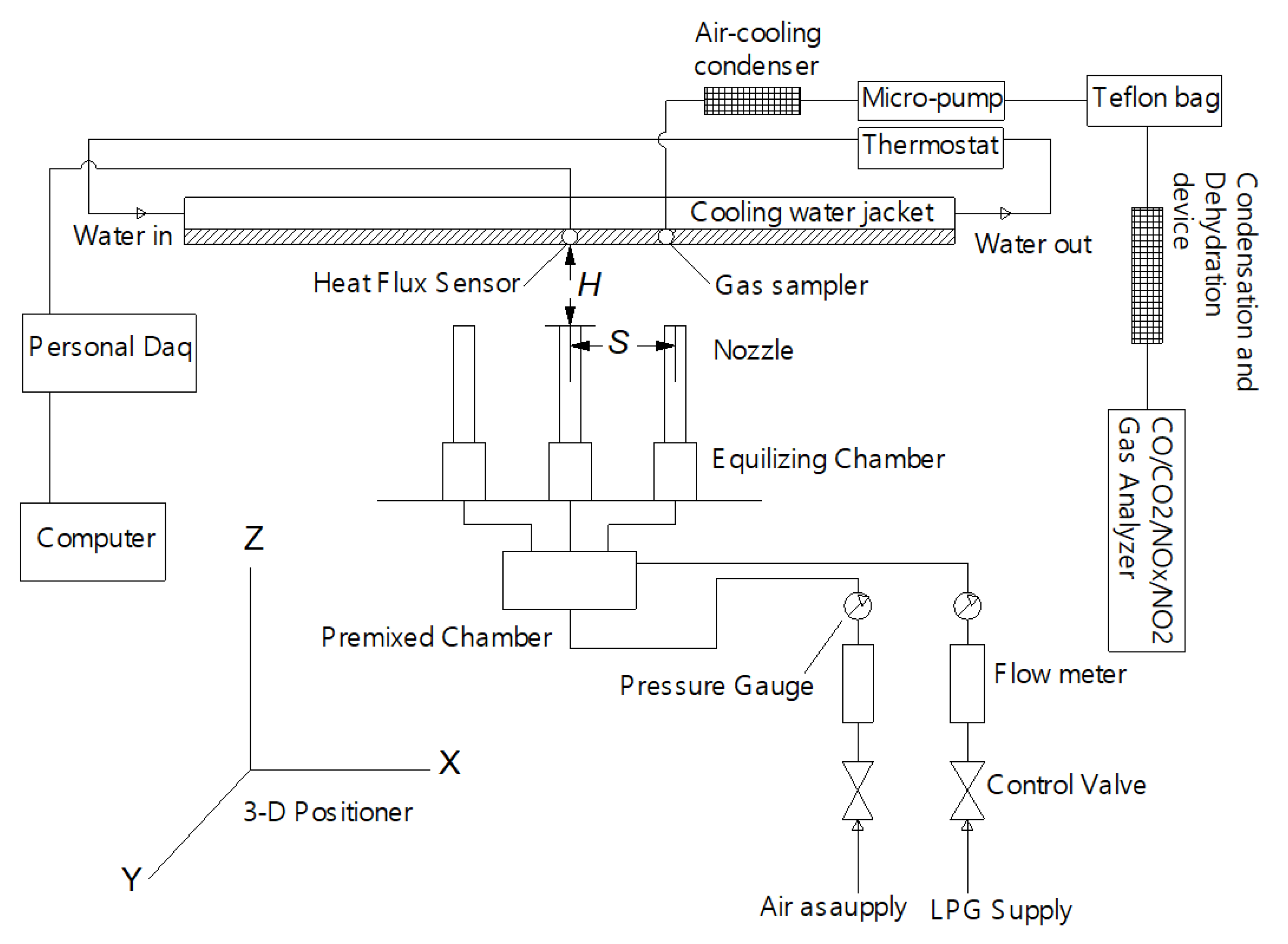
2. Experimental Setup
3. Results and Discussions
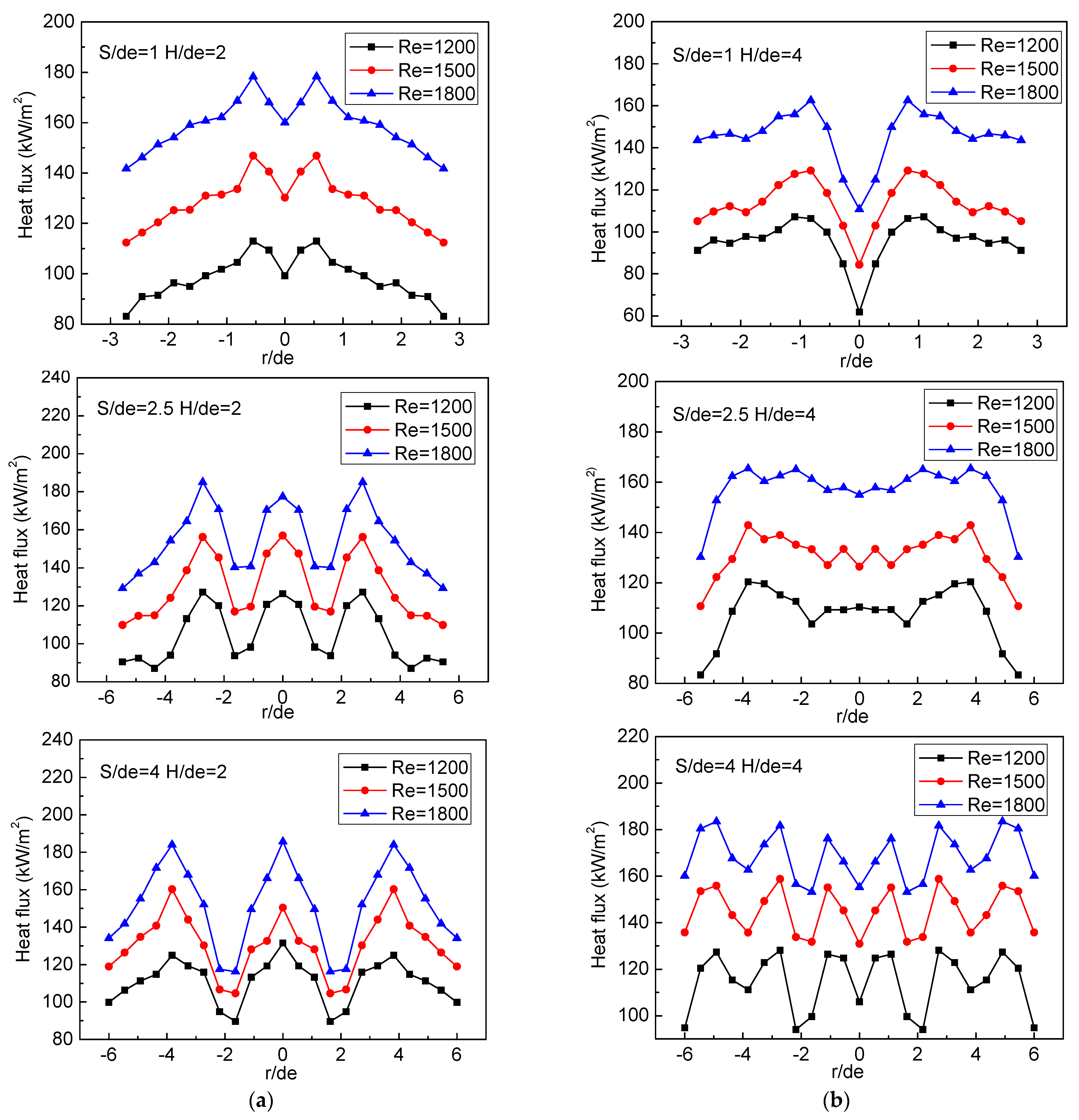
3.1. Heat Flux Distributions
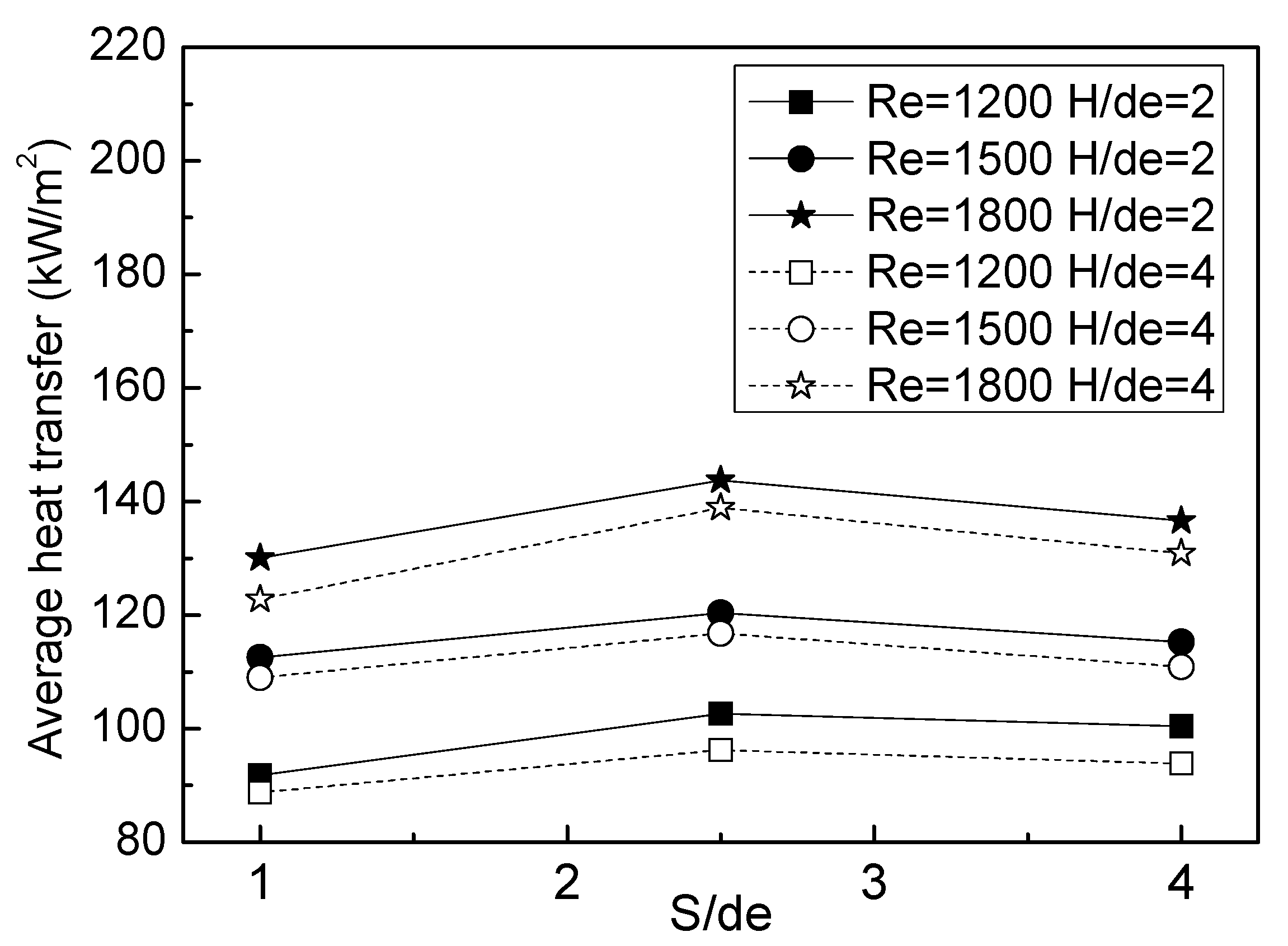
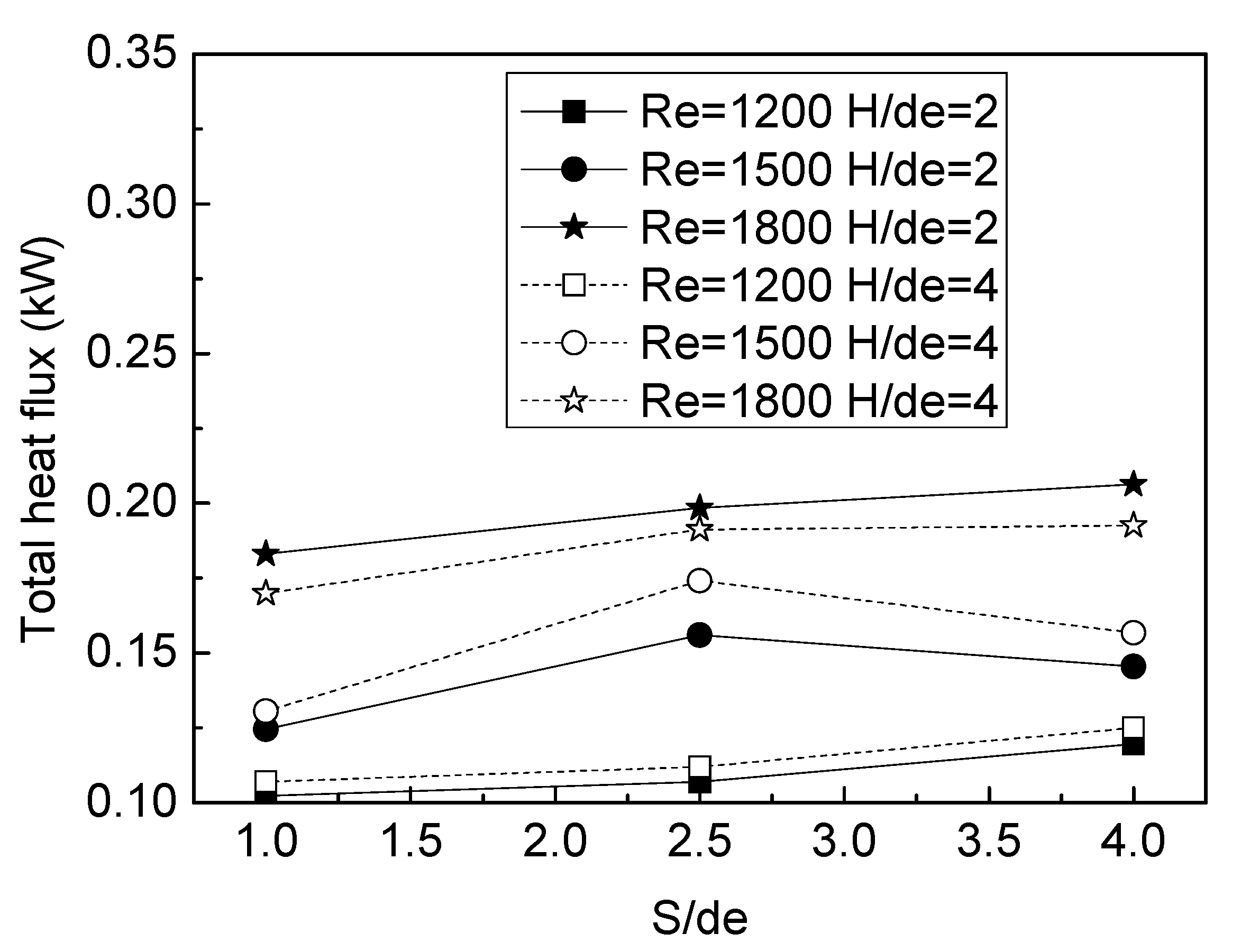
3.2. Average and Total Heat Flux
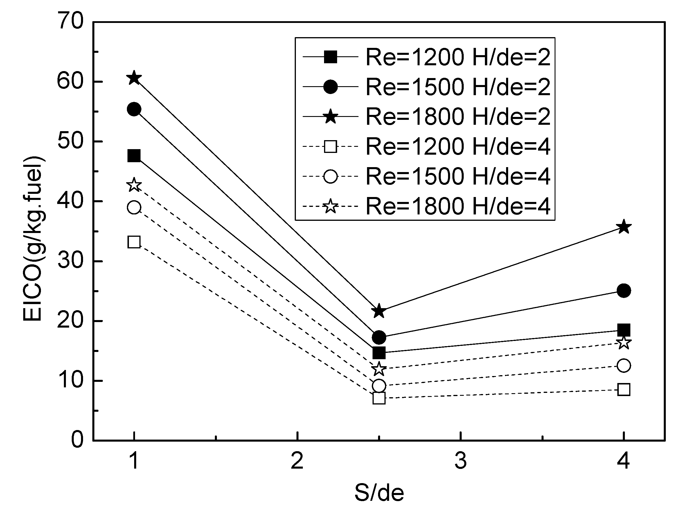
3.3. Exhaust Emissions of CO, CO2, and NOx
3.4. Comparison of the Heat Transfer and Emission Characteristic of Slot and Circular Jet Flames
3.4.1. Comparison of the Average Heat Flux
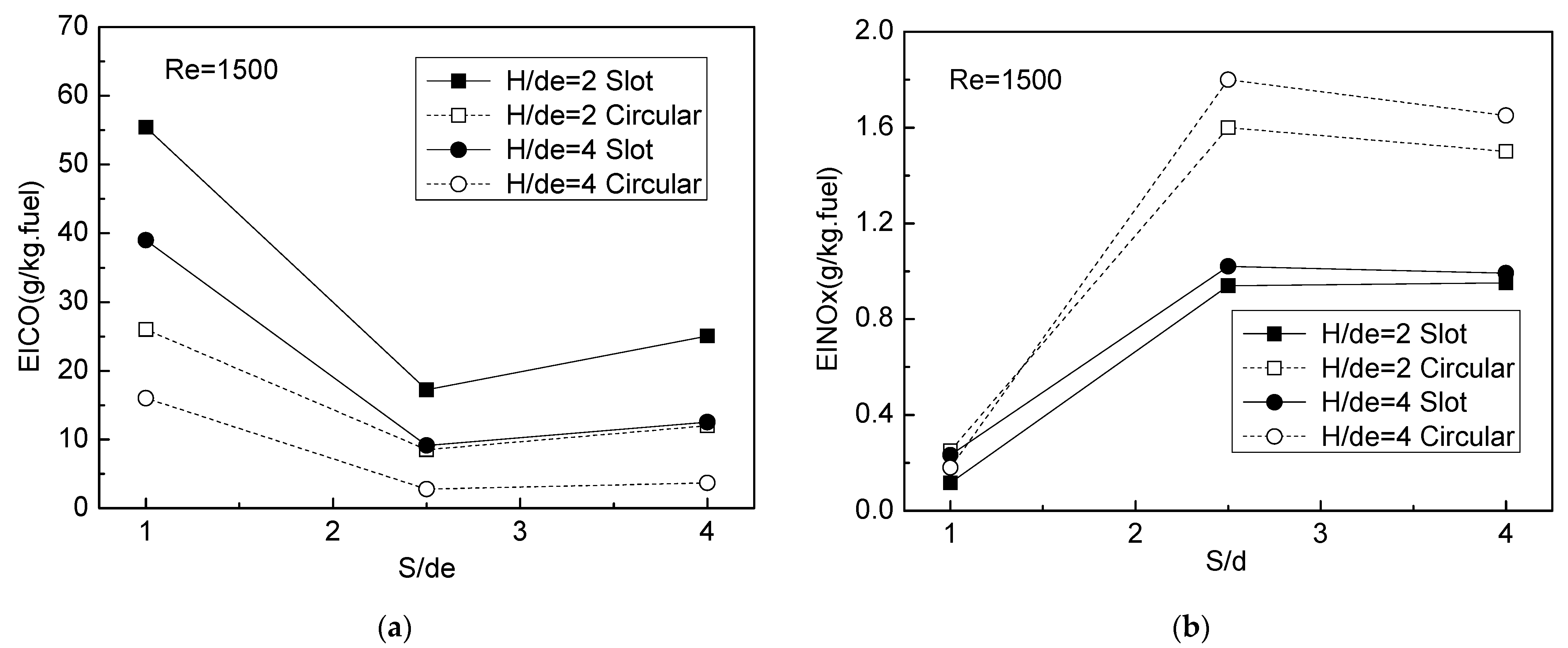
3.4.2. Comparison of the Emission Characteristics
4. Conclusions
- The local heat flux can be codetermined by the jet interaction, cool core of the flame, and the Reynolds number. The strong jet interaction can result in the lower local heat flux due to the worse field synergy, while the cool core can make sense at a larger jet-to-jet spacing to reduce the local heat flux at the flame axis. In addition, although the larger Reynolds number can make the jet interaction more intensive, it can improve the convective heat transfer more effectively and results in the increased local heat flux. The more uniform heat flux distribution and higher total heat flux can be obtained at the moderate jet-to-jet spacing, large jet-to-plate distance, and higher Reynolds number.
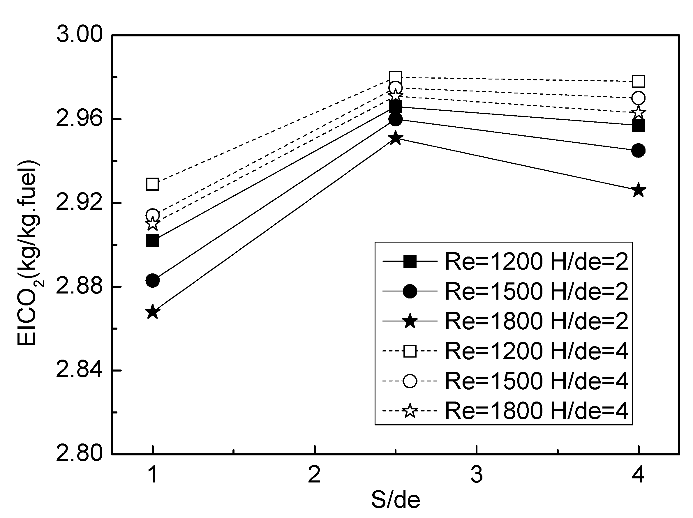
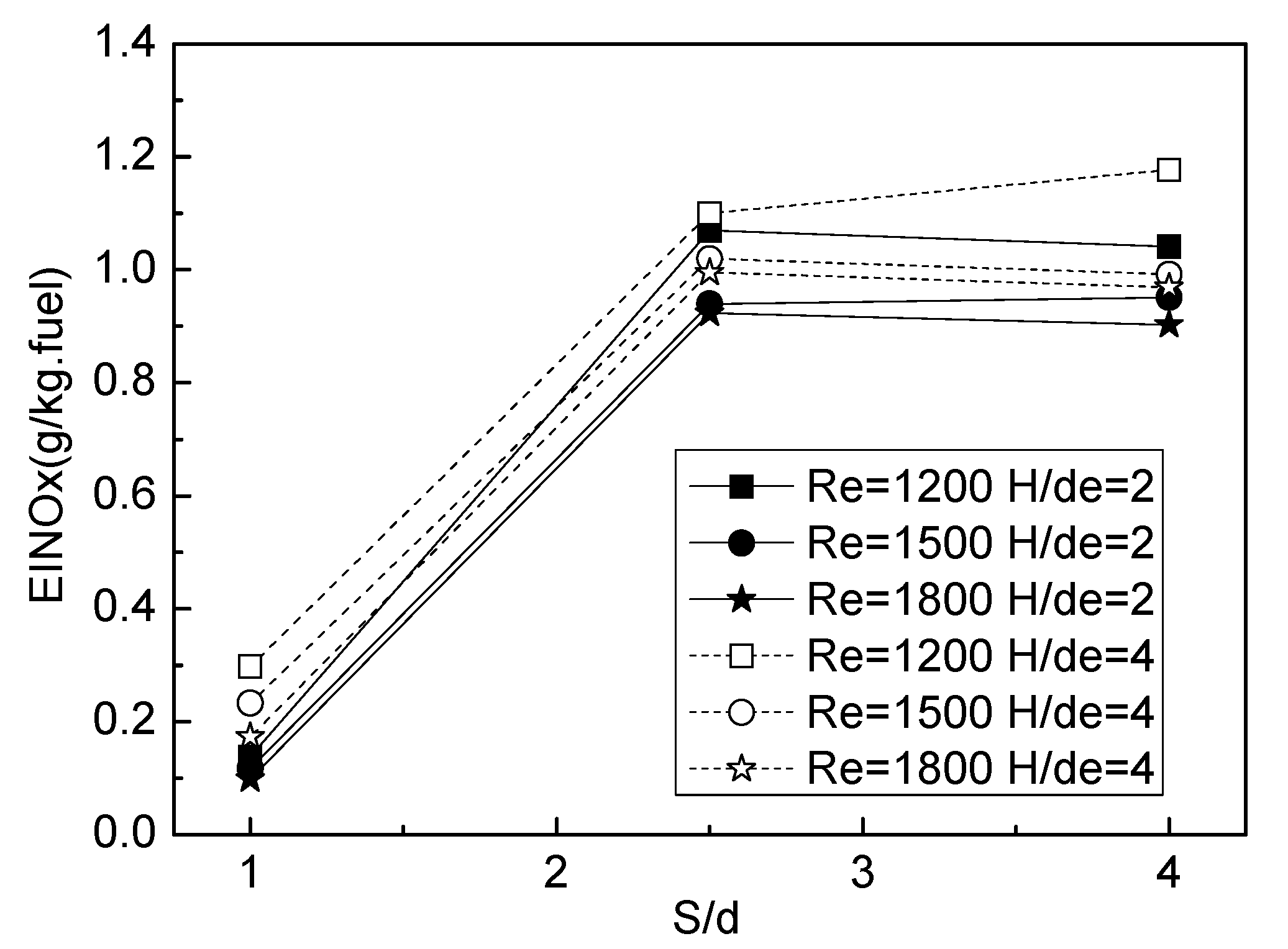
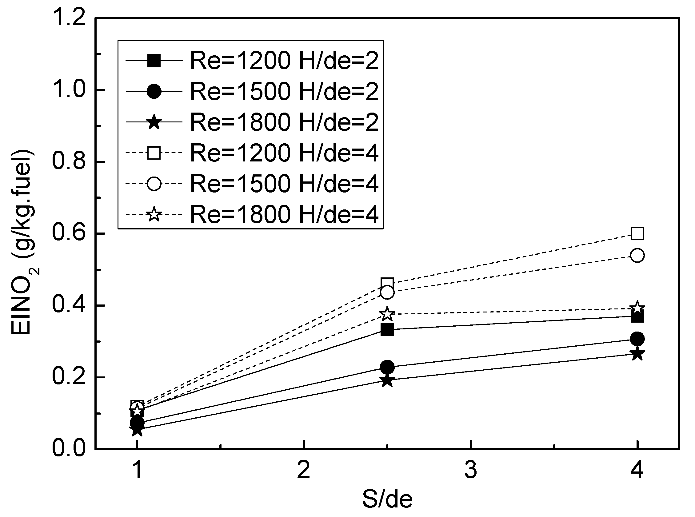
- EICO emission is influenced by the combined effects of jet-to-jet spacing, jet-to-plate distance, and higher Reynolds number. Small jet-to-jet spacing, a lower jet-to-plate distance, and a higher Reynolds number can provide insufficient oxygen in the burned gases of the flame array due to the relatively worse ambient air entrainment, which results in the higher EICO and lower EICO2. To obtain the better combustion efficiency and lower EICO emission, the moderate jet-to-jet spacing, larger jet-to-plate distance, and relatively higher Reynolds number are suggested for the slot jet flame array. In addition, the EINOx emission increases with the increased jet-to-plate distance and the lower Reynolds number due to the more available oxidizer and longer residence time. Thus, it is found that there exists a trade-off between the EICO and EINOx.
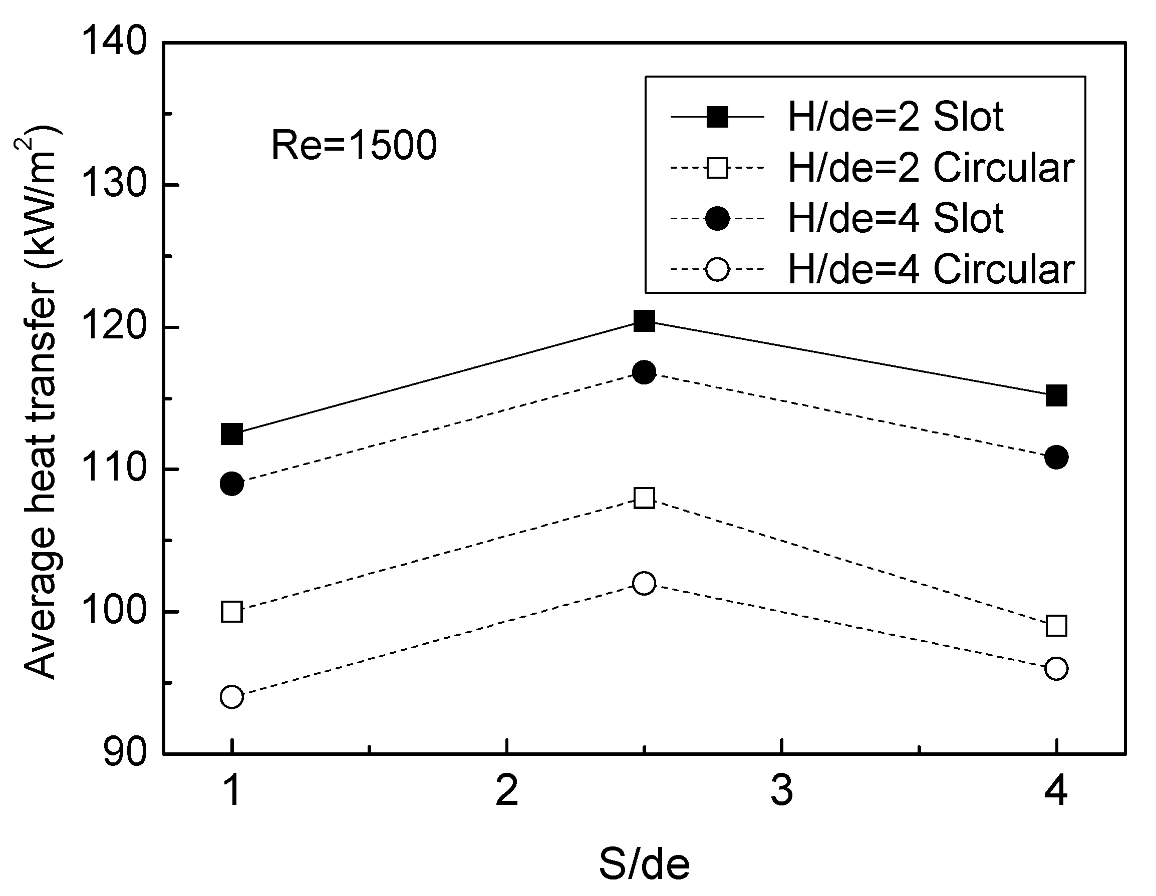
- Compared with multiple circular flame jets, multiple slot flames jets have the higher area-averaged heat flux due to the larger heating area and more uniform heat flux distribution, the higher EICO emission, and lower EINOx emission owing to the greater jet interaction suppressing the air entrainment. Hence, it is known that the slot flame array can have better heating performance but higher pollutant emissions than the circular flame array.
Author Contributions
Funding
Institutional Review Board Statement
Acknowledgments
Conflicts of Interest
References
- Dong, L.; Leung, C.; Cheung, C.S. Heat transfer of a row of three butane/air flame jets impinging on a flat plate. Int. J. Heat Mass Transf. 2003, 46, 113–125. [Google Scholar] [CrossRef]
- Dong, L.L.; Leung, C.W.; Cheung, C.S. Heat transfer characteristics of a pair of impinging rectangular flame jets. J. Heat Transf. 2003, 125, 1140–1146. [Google Scholar] [CrossRef]
- Zhen, H.; Zhang, L.; Wei, Z.; Chen, Z.; Huang, Z. A numerical study of the heat transfer of an impinging round-jet methane Bunsen flame. Fuel 2019, 251, 730–738. [Google Scholar] [CrossRef]
- Wei, Z.; Zhen, H.; Leung, C.; Cheung, C.; Huang, Z. Heat transfer characteristics and the optimized heating distance of laminar premixed biogas-hydrogen Bunsen flame impinging on a flat surface. Int. J. Hydrogen Energy 2015, 40, 15723–15731. [Google Scholar] [CrossRef]
- Wei, Z.; Leung, C.W.; Cheung, C.S.; Huang, Z. Effects of H2 and CO2 addition on the heat transfer characteristics of laminar premixed biogas–hydrogen Bunsen flame. Int. J. Heat Mass Transf. 2016, 98, 359–366. [Google Scholar] [CrossRef]
- Kwok, L.; Leung, C.; Cheung, C. Heat transfer characteristics of an array of impinging pre-mixed slot flame jets. Int. J. Heat Mass Transf. 2005, 48, 1727–1738. [Google Scholar] [CrossRef]
- Chander, S.; Ray, A. Heat transfer characteristics of three interacting methane/air flame jets impinging on a flat surface. Int. J. Heat Mass Transf. 2007, 50, 640–653. [Google Scholar] [CrossRef]
- Mohr, J.W.; Seyed-Yagoobi, J.; Page, R.H. Heat transfer from a pair of radial jet reattachment flames. J. Heat Transf. 1997, 119, 633–635. [Google Scholar] [CrossRef]
- Wu, J.; Seyed–Yagoobi, J.; Page, R. Heat transfer and combustion characteristics of an array of radial jet reattachment flames. Combust. Flame 2001, 125, 955–964. [Google Scholar] [CrossRef]
- Zhen, H.S.; Wei, Z.L.; Leung, C.W.; Cheung, C.S.; Huang, Z.H. Emission of impinging biogas/air premixed flame with hydrogen enrichment. Int J Hydrogen Energy 2016, 41, 2087–2095. [Google Scholar] [CrossRef]
- Wei, Z.; Zhen, H.; Leung, C.; Cheung, C.; Huang, Z. Experimental and numerical study on the emission characteristics of laminar premixed biogas-hydrogen impinging flame. Fuel 2017, 195, 1–11. [Google Scholar] [CrossRef]
- Mishra, D. Emission studies of impinging premixed flames. Fuel 2004, 83, 1743–1748. [Google Scholar] [CrossRef]
- Mohr, J.; Seyed-Yagoobi, J.; Page, R. Combustion measurements from an impinging radial jet reattachment flame. Combust. Flame 1996, 106, 69–80. [Google Scholar] [CrossRef]
- Li, H.; Zhen, H.; Leung, C.; Cheung, C.S. Effects of plate temperature on heat transfer and emissions of impinging flames. Int. J. Heat Mass Transf. 2010, 53, 4176–4184. [Google Scholar] [CrossRef]
- Wei, Z.; Zhen, H.; Leung, C.; Cheung, C.; Huang, Z. Effects of H2 addition on the formation and emissions of CO/NO2/NOx in the laminar premixed biogas-hydrogen flame undergoing the flame-wall interaction. Fuel 2020, 259, 116257. [Google Scholar] [CrossRef]
- Wei, Z.; Zhen, H.; Leung, C.; Cheung, C.; Huang, Z. Effects of unburned gases velocity on the CO/NO2/NOx formations and overall emissions of laminar premixed biogas-hydrogen impinging flame. Energy 2020, 196, 117146. [Google Scholar] [CrossRef]
- Pérez, S.; Del Molino, E.; Barrio, V.L. Modeling and Testing of a milli-structured reactor for carbon dioxide methanation. Int. J. Chem. React. Eng. 2019, 17. [Google Scholar] [CrossRef]
- Yin, C.; Qiu, S.; Zhang, S.; Sher, F.; Zhang, H.; Xu, J.; Wen, L. Strength degradation mechanism of iron coke prepared by mixed coal and Fe2O3. J. Anal. Appl. Pyrolysis 2020, 150, 104897. [Google Scholar] [CrossRef]
- Qureshi, Y.; Ali, U.; Sher, F. Part load operation of natural gas fired power plant with CO2 capture system for selective exhaust gas recirculation. Appl. Therm. Eng. 2021, 190, 116808. [Google Scholar] [CrossRef]
- Kline, S.J.; McClintock, F. Describing uncertainties in single-sample experiments. Mech. Eng. 1953, 75, 3–8. [Google Scholar]
- Saha, C.; Ganguly, R.; Datta, A. Heat transfer and emission characteristics of impinging rich methane and ethylene jet flames. Exp. Heat Transf. 2008, 21, 169–187. [Google Scholar] [CrossRef]
- Dong, L.; Cheung, C.; Leung, C. Heat transfer from an impinging premixed butane/air slot flame jet. Int. J. Heat Mass Transf. 2002, 45, 979–992. [Google Scholar] [CrossRef]
- Zhen, H.; Leung, C.W.; Cheung, C.S. A comparison of the heat transfer behaviors of biogas—H2 diffusion and premixed flames. Int. J. Hydrogen Energy 2014, 39, 1137–1144. [Google Scholar] [CrossRef]
- Wei, Z.; Zhen, H.; Leung, C.; Cheung, C.; Huang, Z. Formations and emissions of CO/NO2/NOx in the laminar premixed biogas-hydrogen flame undergoing the flame-wall interaction: Effects of the variable CO2 proportion. Fuel 2020, 276, 118096. [Google Scholar] [CrossRef]
- Hou, S.-S.; Ko, Y.-C. Effects of heating height on flame appearance, temperature field and efficiency of an impinging laminar jet flame used in domestic gas stoves. Energy Convers. Manag. 2004, 45, 1583–1595. [Google Scholar] [CrossRef]


Publisher’s Note: MDPI stays neutral with regard to jurisdictional claims in published maps and institutional affiliations. |
© 2021 by the authors. Licensee MDPI, Basel, Switzerland. This article is an open access article distributed under the terms and conditions of the Creative Commons Attribution (CC BY) license (https://creativecommons.org/licenses/by/4.0/).
Share and Cite
Zhen, H.; Du, B.; Liu, X.; Liu, Z.; Wei, Z. Experimental Investigation on the Heat Flux Distribution and Pollutant Emissions of Slot LPG/Air Premixed Impinging Flame Array. Energies 2021, 14, 6255. https://doi.org/10.3390/en14196255
Zhen H, Du B, Liu X, Liu Z, Wei Z. Experimental Investigation on the Heat Flux Distribution and Pollutant Emissions of Slot LPG/Air Premixed Impinging Flame Array. Energies. 2021; 14(19):6255. https://doi.org/10.3390/en14196255
Chicago/Turabian StyleZhen, Haisheng, Baodong Du, Xiaoyu Liu, Zihao Liu, and Zhilong Wei. 2021. "Experimental Investigation on the Heat Flux Distribution and Pollutant Emissions of Slot LPG/Air Premixed Impinging Flame Array" Energies 14, no. 19: 6255. https://doi.org/10.3390/en14196255
APA StyleZhen, H., Du, B., Liu, X., Liu, Z., & Wei, Z. (2021). Experimental Investigation on the Heat Flux Distribution and Pollutant Emissions of Slot LPG/Air Premixed Impinging Flame Array. Energies, 14(19), 6255. https://doi.org/10.3390/en14196255