Article

A Rationalised CFD Design Methodology for Turgo Turbines to Enable Local Manufacture in the Global South

1
Electrical Energy Management Group, University of Bristol, Bristol BS8 1TR, UK
2
Tidal Development, Liverpool City Authority, Liverpool L3 1BP, UK
3
Lancaster University Renewable Energy Group & Fluid Machinery Group, Lancaster University, Lancaster LA1 4YW, UK
*
Author to whom correspondence should be addressed.
Energies 2021, 14(19), 6250; https://doi.org/10.3390/en14196250
Submission received: 28 May 2021 / Revised: 10 August 2021 / Accepted: 22 September 2021 / Published: 1 October 2021
(This article belongs to the Special Issue Next Generation of Hydraulic Machines)

Abstract

:
In the Global South, pico- and micro-hydropower turbines are often made by local workshops. Despite several advantageous features, e.g., a high power density and capacity to handle silt, there is no commonly available Turgo turbine design appropriate for local manufacture. Technological developments including the internet, CAD, and additive manufacturing increase the opportunity to precisely transfer designs around the world. Consequently, design improvements can be shared digitally and used by manufacturers in their local context. In this paper, a rationalised CFD approach was used to guide simple design changes that improve the efficiency of a Turgo turbine blade. The typical manufacturing capacity of the micro-hydropower industry in Nepal was used to rationalise the variation of potential design changes. Using the geometry and operational parameters from an existing design as a benchmark, a two-blade, homogenous, multiphase model was developed and run using the commercial code ANSYS CFX. Initially, it was identified that the jet aim position had a significant effect on the efficiency. A design of experiments’ approach and subsequent analysis of numerical and visual results were used to make design changes that resulted in an improvement in efficiency from 69% to 81%. The design changes maintained the simple profile of the blade, ensuring that the resulting design was appropriate for manufacture in a local workshop.

1. Introduction

Pico- (<5 kW) and micro- (<100 kW) scale hydropower are often used for rural electrification in the Global South [1]. The term “Global South” usually refers to the regions of Latin America, Asia, Africa, and Oceania [2]. Within these regions, there are many countries where the geography is appropriate for hydropower and hydro-turbines are manufactured by local workshops [3]. Benefits of local production include lower cost for end users, reduced downtime, and increased availability of local knowledge [4,5]. Despite these benefits, the range in the types of turbines manufactured by local workshops is often limited to Pelton turbines, to serve high head sites, and Crossflow turbines, to serve low head sites. For both turbine types, locally manufactured turbines usually achieve efficiencies in the range of 65–80% [6]. Less common examples of locally manufactured hydropower technology include the propeller turbine [7] and the waterwheel [8]. Consequently, there are opportunities to extend the available range of locally manufactured turbines and to improve their efficiencies. There are several features of the Turgo turbine that suggest it could be appropriate for use in the Global South [9]. Firstly, compared to the Pelton, the entry and exit of water flow on opposite sides of the runner mean that Turgo runners have higher capacity and can be more compact, reducing their cost [10]. Secondly, as the jet is directed at a wider surface, blade abrasion occurs more evenly making them reliable where rivers have a high silt content [10]. Finally, for workshops that produce only Pelton and Crossflow turbines, there are certain sites (with an intermediate head) where neither turbine is the optimum choice. For these sites, a Pelton turbine may be large and expensive due to a slow rotational speed, while Crossflow turbines are likely to be narrow in width and less efficient [11]. Therefore, for these sites, the Turgo turbine may offer a superior alternative. Currently, there is little evidence of the manufacture of the Turgo turbine in local workshops. Many of its components are also common to Pelton turbines; however, the complex blade profile has been cited as a barrier to production in local workshops [10]. Therefore, to enable its production, a locally appropriate blade design is required. Local workshops have tended to manufacture turbines based on information taught in person or available in literature. Today, the internet, increased access to computer-aided design (CAD), and additive manufacturing provide new opportunities for sharing design information and producing new products. Open-source designs for a wide range of products are available online allowing anyone to access digital designs and communicate with fellow designers and manufacturers [12,13,14]. Through CAD, these designs can be adapted to specific local requirements, while additive manufacturing enables prototyping and the production of casting patterns. In the design of hydropower equipment, these technologies allow 3D designs to be produced and shared using the internet, with rapid prototyping used to produce models of complex turbine geometry. As such, new designs and developments in hydrodynamic design can be transferred around the world.
For the Turgo turbine, a patent held by the British turbine and pump manufacturer Gilkes until 1983 has limited the availability of designs [10]. Through academic research, there have been some Turgo design developments, although much of this research has been focused on Gilkes’ own designs [15]. Some work explores important parameters in the performance of market-ready, simplified Turgo designs [16,17,18]. Elsewhere, approaches for efficiency improvement have focused on the Turgo runner design [19,20,21]. In both [16] and [18], experimental studies were used to evaluate the importance of experimental parameters such as the nozzle diameter, number of nozzles, jet angle, number of blades, and the jet impact location. In [17], the experimental performance of Pelton and Turgo turbines in relation to variations in speed ratio and jet aim position was studied. These studies are useful in identifying the most important experimental parameters affecting Turgo turbine efficiency where the use of response surface methodologies enabled prediction of the conditions that would lead to highest efficiencies [16,18]. However, these studies were unable to provide insight into the key design parameters for the Turgo blade itself. In [20], a 2D, quasi-steady-state model was used to inform design changes to a Turgo blade that resulted in an improvement of efficiency of 5% experimentally. Correa et al. [19] used analytical approaches to develop a number of models of Turgo turbine performance. Subsequently, the authors used a Rankine ovoid streamlines function to develop a Turgo blade design that achieved an efficiency of 80.8% when simulated using computational fluid dynamics (CFD) [22]. In [21], a Lagrangian-based CFD method was used to optimise an existing blade design based on the variation of 11 design variables. The optimised runner improved in efficiency by 6%. These studies have not resulted in a design appropriate for manufacture in local workshops; however, they do show the different approaches that can be used in runner design improvement.
In general, the creation of turbine runner designs is dependent on theoretical, computational, and experimental methods, used individually or in combination [23]. Historically, for impulse turbines, there are published examples of the use of theoretical methods to develop both Pelton [24] and Turgo [25] turbine designs. For Pelton turbines, designs based on theoretical methods have been published and made available in formats applicable to local manufacture [26,27]. An example is found in [26] where Thake provides the dimensions of a Pelton bucket in relation to the calculated jet diameter. Despite their simplicity, designs like these have still relied on experimental testing for their validation. Collecting experimental data is expensive and time consuming, particularly when used in the improvement of runner designs, where individual geometrical changes require the production of new runners. In the last 25 years, CFD has been used to explore turbine performance and make improvements to designs [23,28,29]. CFD has allowed multiple changes to runner designs to be concurrently explored. Where the results of CFD have been compared to experimental testing results, it has been shown to give a reasonable agreement. Due to the knowledge, experience, and computational power required, the use of CFD within hydropower has largely been for academic and industrial applications focused on the improvement of high-performance turbines for medium- and large-scale hydropower projects. However, when compared with the use of theoretical modelling and experimental testing, commercially available CFD software can be used to quickly and cost effectively optimise simple turbine designs to improve efficiency. Compared to theoretical modelling and experimental testing, simulation in CFD provides greater fidelity in the design process, allowing the results of design changes to be established quickly and compared quantitatively.
The availability of CFD, CAD, and the internet provides new opportunities for the development and sharing of turbine designs. Currently, there is not a freely available design for the Turgo turbine that is appropriate for the manufacturing processes available in local workshops in the Global South. In this paper, a rationalised CFD design methodology was used where the design progression is bounded by the specific manufacturing limitations in a local context. A design of experiments (DOE) approach was used to identify the key overall dimensions (height, width, and depth) and the pertinent geometrical features that lead to improvements in efficiency. The methodology enables rapid improvement of the blade efficiency while maintaining a focus on the ability to locally manufacture the resulting design.

2. Context for Local Manufacture

To rationalise the CFD process, there is value in considering the potential method of production in a local workshop. By placing restrictions on the potential changes to the blade design, it was possible to improve the efficiency with confidence that the final design could be manufactured.
In this paper, the specific local context considered was Nepal. Turbines have been made in Nepal since the 1960s [30]. Today, micro-hydropower companies in Nepal usually produce only Pelton and Crossflow turbines [31]. The simple Pelton bucket design published by Thake was initially developed in Nepal for use with basic sand casting and machining facilities [26]. Similarly, the development of a simplified Crossflow turbine took place at workshops in Nepal [32], and continues to be manufactured. Workshops typically own engine lathes, pillar drills, vertical milling machines, and sheet metal benders and use oxy-acetylene for cutting and welding [33]. In the manufacture of Pelton turbines, the runner buckets are produced at separate casting companies. Cast steel, brass, and bronze are often used to cast individual buckets. These are ground to improve the surface finish and welded or bolted to a hub.
In this study, the runner from a XJ25-1.5DCT4-Z Turgo turbine was used as the starting point for design improvement. The manufacturer of this runner has reported a hydrodynamic efficiency of 70% [34]. The runner was selected as a baseline due to its market availability and simple geometric form and the ability to easily test it experimentally. The blades of the runner were made from sheet metal and pressed into a hemispherical form. It was expected that simple geometrical changes could be made to improve efficiency. In the context of Nepal, the repeatability, familiarity, and the potential for greater complexity meant casting was chosen as the production method for the final, improved design. Casting could also be integrated with the use of CAD and additive manufacturing to produce identical designs in multiple locations. For future production, local casting capacity (e.g., shrinkage and machining allowances) could be incorporated into CAD models. A resulting CAD file could be shared, using the internet, in an appropriate design format for production of a rapid prototype. The resulting prototype can be provided to the casting company and used as a pattern. Once complete, the cast blades can be finished and assembled by a manufacturing company.
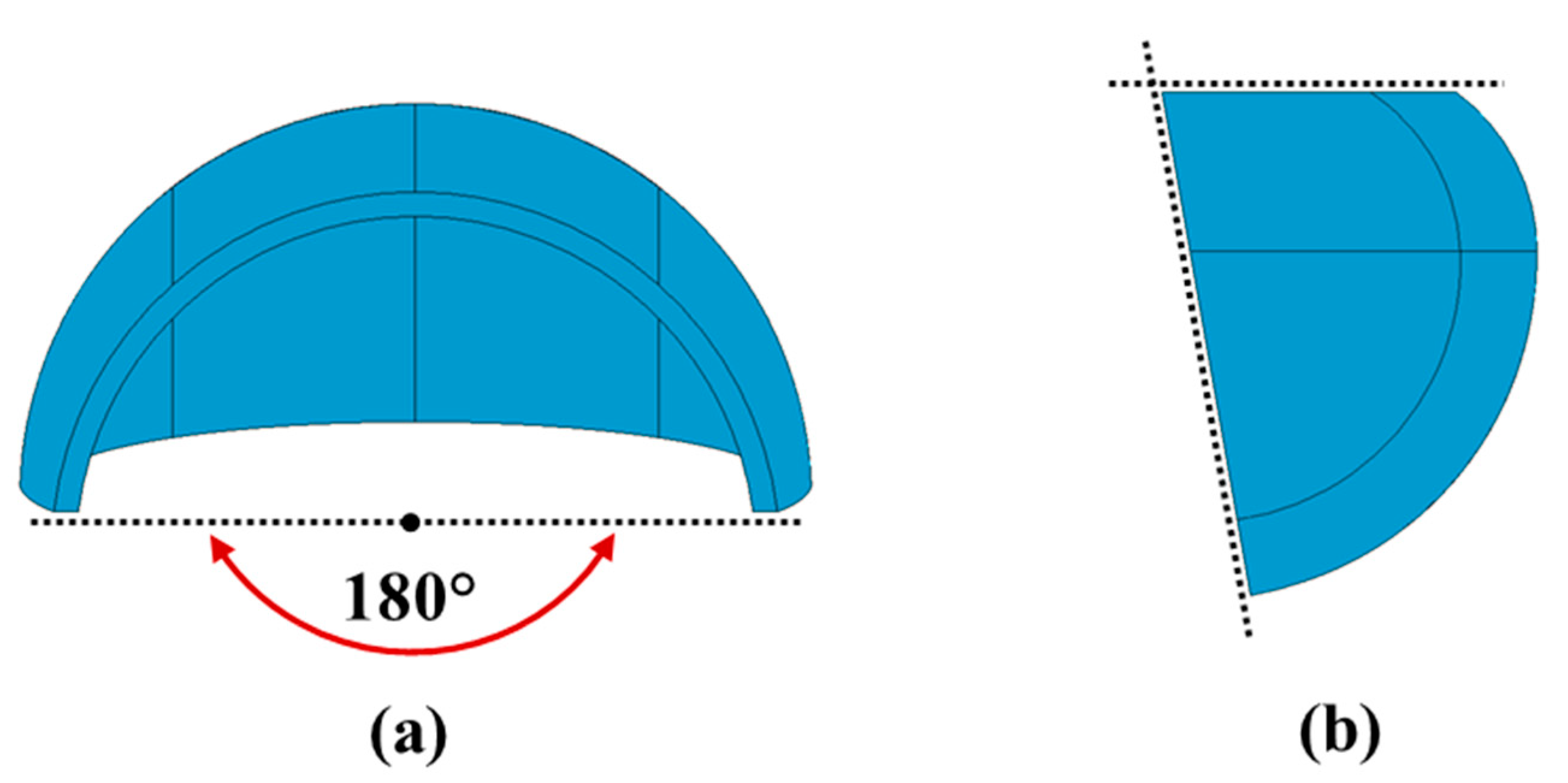
The selection of a production method led to several restrictions to the design. Applying these enabled a rationalised approach to the design development where geometric changes impractical for production were not considered. The restrictions applied in the development process are listed below. Figure 1 shows several of these restrictions visually.
  • A minimum thickness of 2.5 mm should be maintained and thickness should be consistent throughout the blade. In available literature [35] and responses from a casting company in Nepal, 3 mm is cited as a minimum section thickness for sand casting in brass [28]. Through a subsequent grinding process, this could reasonably be reduced to 2.5 mm.
  • The blade should be approximately hemi-spherical in shape. To ensure that the resulting cast blade can be removed, the angle between the edges of the blade should not be less than 180°, as shown in Figure 1a. This enables easier access to the internal surface of the blade for grinding.
  • There should be no undercuts or re-entrant features. The blade surface should not include features (with abrupt directional changes) that are susceptible to poor flow of the molten casting material.
  • The top and front faces of the blade should be maintained as flat plain surfaces, as shown in Figure 1b. Plain surfaces increase the simplicity of the subsequent machining processes.

3. Numerical Modeling

3.1. Background

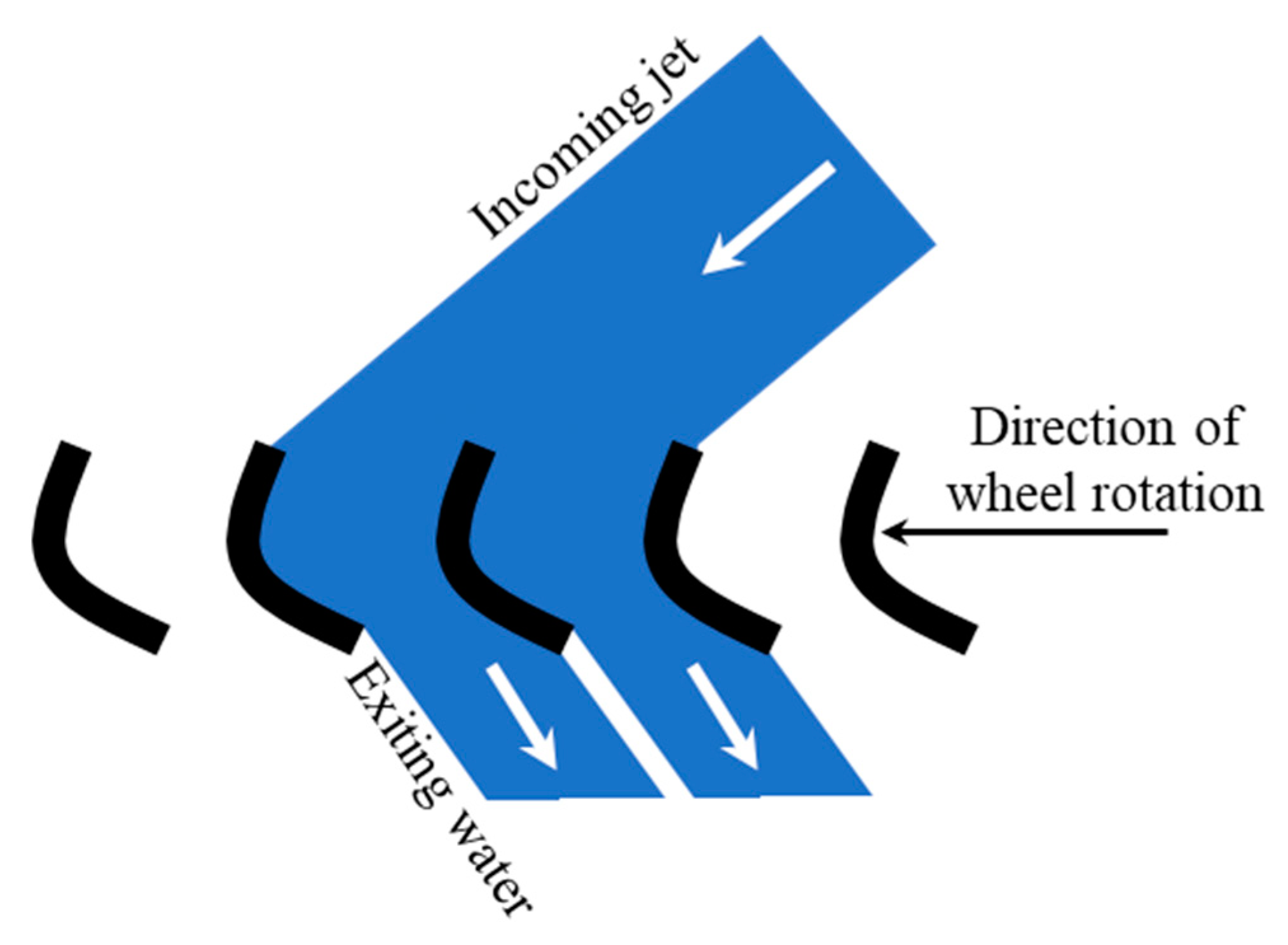
In the operation of Turgo turbines, the change in momentum of a jet interacting with the turbine runner results in the generation of torque. Figure 2 shows the interaction between a jet and a series of Turgo blades. Unlike the Pelton, the jet is inclined at an angle to the runner, usually between 20° and 22.5°, meaning that the water enters and exits on different sides of the runner [1].
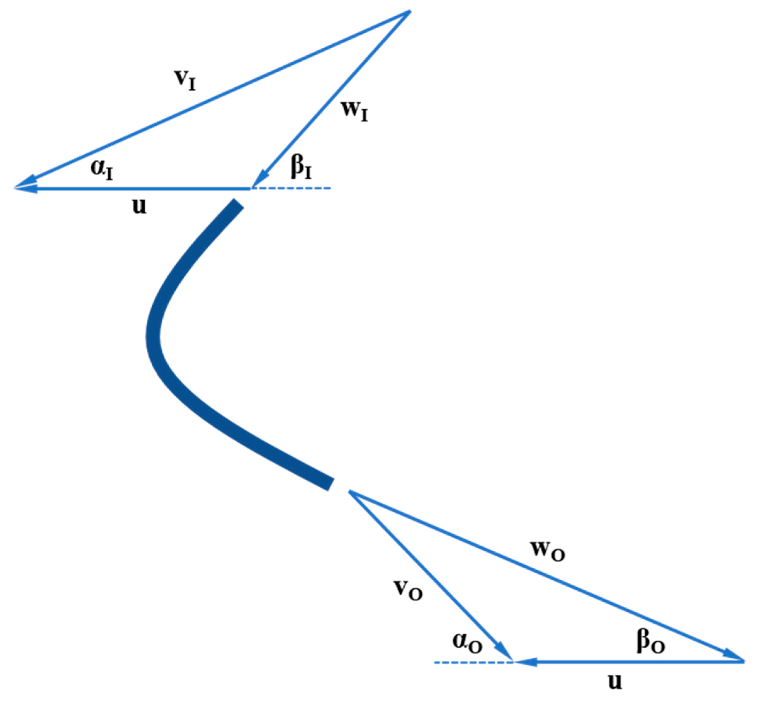
To aid development of a CFD model and the evaluation of subsequent results, it is worth considering the motion of the fluid through the turbine. In Figure 3, a diagram is shown for the water passing through a single blade, with velocity triangles shown for the inlet and outlet. It is assumed that all of the jet impacts at the same radius and that the water enters and exits in the same vertical plane. Radial movement of the water is neglected. In Figure 3, the following nomenclature is used for the diagram notation: The v is the absolute velocity of the water, w is the resultant velocity of the water, u is the peripheral velocity of the runner at the radius considered, α is the angle between the runner’s plane of rotation and the jet, and β is the resultant velocity angle. Where relevant, the subscripts I and O are used to indicate inlet and outlet, respectively.
At the point of impact, the blade has a peripheral velocity, u, dependent on the rotational speed of the runner and the radius at which the jet impact is being considered. The water leaves the nozzle and impacts the blade at an absolute velocity, vI. Due to the blade’s movement relative to the jet, the water enters the blade with a relative velocity, wI, with a relative velocity angle of βI. The water passes through the blade and leaves at the outlet with an absolute velocity of vO. The rotational speed of the blade is assumed to be constant as the water travels through the blade; therefore, the peripheral velocity of the blade is also constant. At the outlet, the blade’s movement causes the exiting water to leave with a relative velocity, wO, and a relative velocity angle of βO. The force exerted on the runner depends on the change in momentum of the water through the blade, in its direction of motion, and the mass flow rate of the fluid. Therefore, with reference to the diagram, the rate of change of momentum is the sum of the horizontal (i.e., perpendicular to u) components of vI and vO. From the diagram, it can be seen that the change of momentum will be greatest when the absolute velocity at outlet has no horizontal component, αO = 90°. The torque generated is the product of the force and the radius considered. Finally, the power generated is the product of the blade’s rotational speed and the generated torque.

3.2. Model Geometry and Parameters

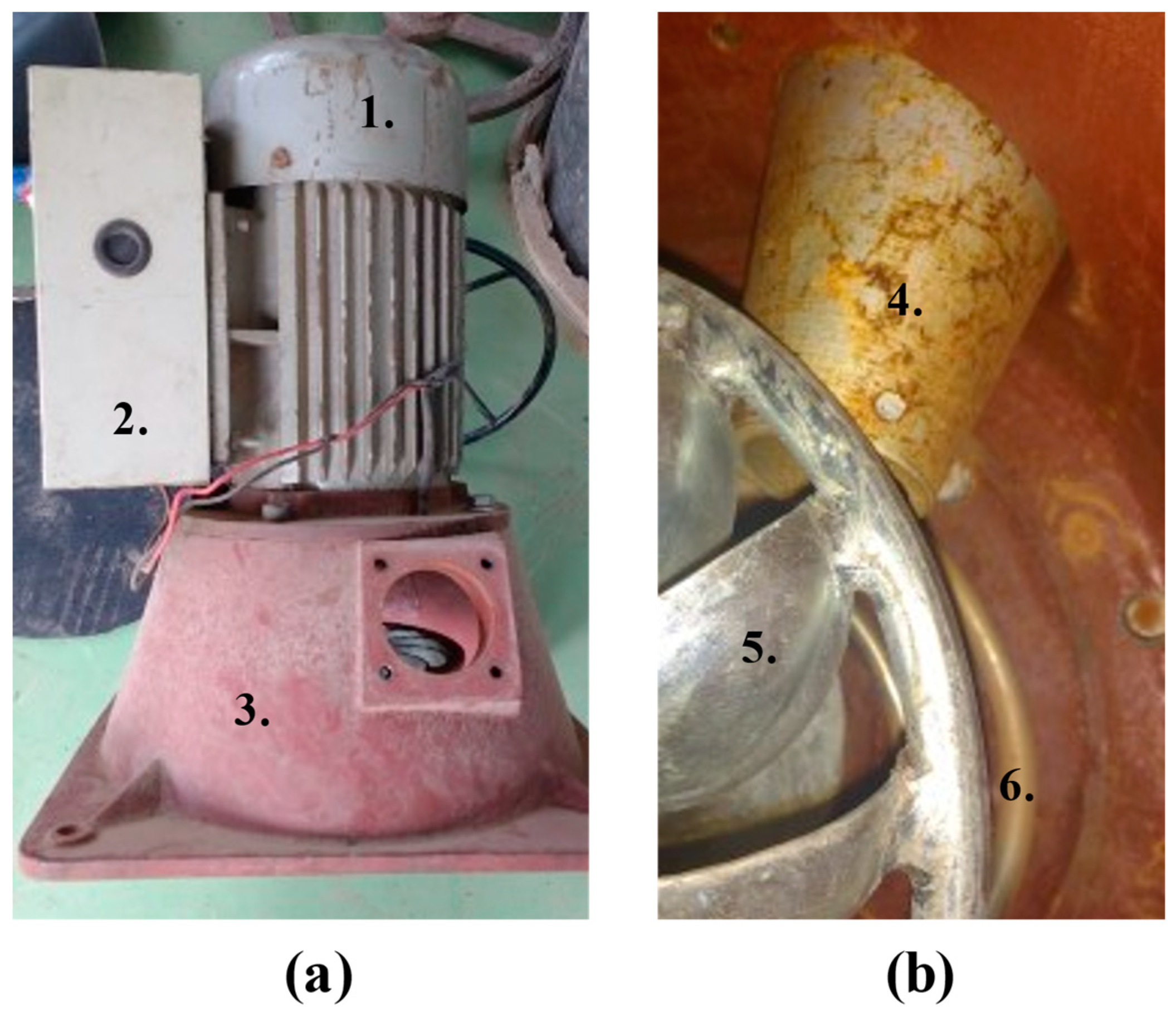
Table 1 lists the turbine specification as provided by the supplier of the XJ25-1.5DCT4-Z Turgo turbine-generator set while Figure 4 shows the key components of the set. It comprises a single nozzle vertical axis Turgo turbine connected directly to the shaft of an induction motor running as a generator. The set includes an air heating element inside the casing that is used as a ballast load. For hydro-turbines at the pico- and micro- scales, it is common to control the turbine electrically rather than mechanically [36]. The electronic load controller “dumps” any excess power to the ballast load to ensure the turbine runs constantly at the generator’s rated speed. The turbine’s nozzle is convergent and has no spear valve; however, flow to the turbine can be controlled and shut off using a gate valve positioned upstream of the nozzle. The gate valve allows the user to crudely vary the head and flow rate into the turbine. The runner of the turbine consists of sheet metal-pressed blades that are welded internally on to a central hub and externally to a concentric outer ring. The profile of the blades is largely uniform; however, evidence of deformation and “crinkling” from the manufacturing process can be seen. The supplier of the turbine also provided replica blades produced using the same process as those on the runner.
Using a Faro Edge Laser Scanner, a blade was scanned in 3D. The resulting point cloud was converted into a mesh using MeshLab and imported into a CAD package to create a solid body. The resolution of the scan was sufficient to capture the physical surface defects. Measurements taken from the imported turbine and alongside the scanned blade were used to develop a CAD model of the complete system.

3.3. CFD Methodology

Compared to reaction turbines, the CFD modelling of impulse turbines has a number of additional challenges due to complex flow phenomena [23]. Despite these challenges, CFD is capable of achieving a good agreement with experimental testing results for impulse turbines [23]. A greater amount of CFD-based research has been focused on the Pelton turbine, with fewer applications for the Turgo turbine. A considerable amount of research has used the Eulerian-based software packages ANSYS Fluent and ANSYS CFX [23]. They have both been shown to achieve comparable results in the study of impulse turbine jets. However, for the modelling of turbine runners where a rotating domain is used, CFX has been used more frequently. Studies with Pelton runners have shown that simulations can be simplified to use fewer than the total number of buckets; studies have used seven [37], three [38] and even two buckets [39] to represent the complete runner. Research has explored the use of different multiphase (e.g., homogenous and inhomogeneous) and turbulence models (e.g., k-ω SST and k-ε). All of these models have been shown to be viable and useful in particular circumstances; however, a combination of a homogenous multiphase model with a k-ω SST turbulence model has become the most commonly used [23,38,40]. This combination has also been used to simulate a Turgo turbine using a two-blade model [15,41]. Within the two-blade model, the rotation of the blades through the jet causes the flow to be ‘chopped’ or segmented. The result is that a parcel of water moves between each pair of blades. The resultant torque depends upon the generation of torque at the surfaces that bound the parcel. Therefore, the resultant torque is the sum of the torque on the inside surface of the first blade and the outside surface of the second blade. Assuming that the geometry of all blades is the same, the flow between the blades can be treated as periodic, defined by the geometries of the front and back surface. Therefore, in combination with the rotational speed, the resultant torque for the passage of two blades can be used to calculate the power for the entire runner. For both Turgo [15,41] and Pelton [39,42] turbines, this approach has been shown to provide reliable computational results comparable to those obtained experimentally.
The experiences of previous work with both Pelton and Turgo runners informs the choice of software and modelling parameters; in this study, a rotating two-blade simulation with a homogenous multiphase and k-ω SST turbulence model was used. In addition, a high-resolution numerical scheme and coupled pressure velocity method were used. Within the simulation, the effects of gravity and surface tension were assumed to be negligible. For Turgo turbines, where flow enters and leaves on opposite sides of the runner, the interaction between the runner and casing is minimal (particularly when compared to Pelton turbines) [10]. In this study, the casing interaction was not modelled as it was deemed insignificant in the comparison between different runners.
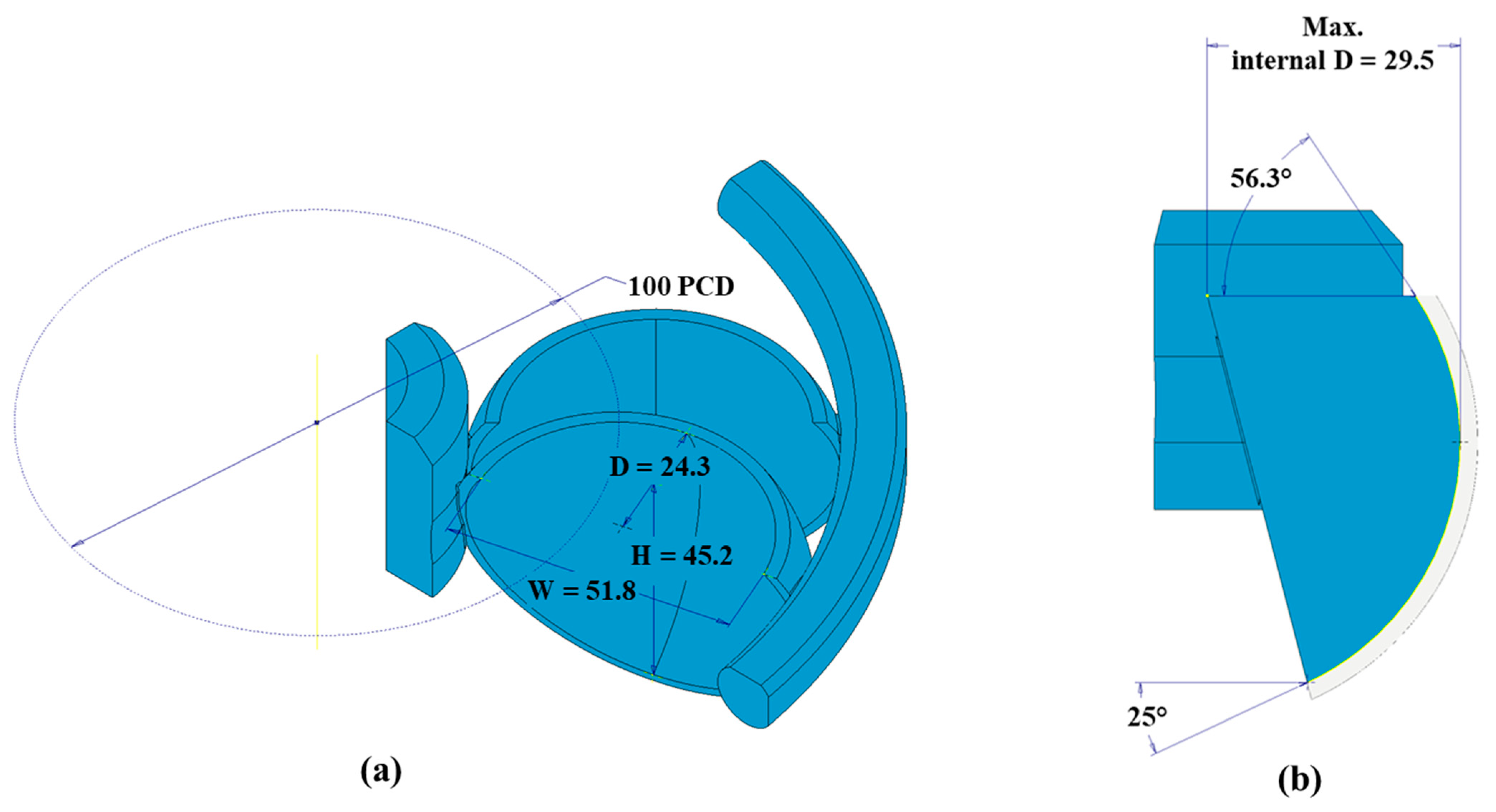
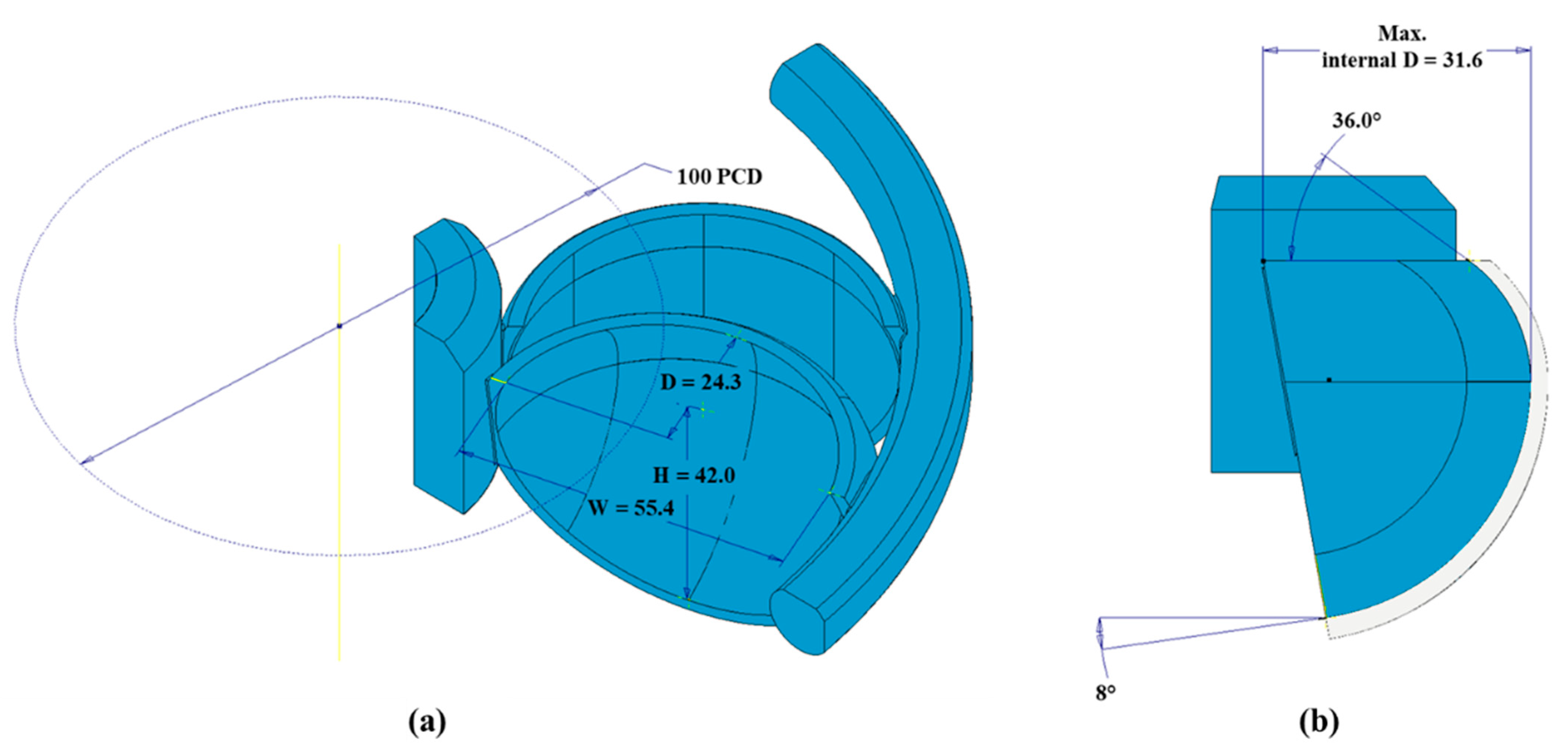
Figure 5 shows the two=blade CAD model for the imported turbine and the geometry in the central plane of the blade. The model includes the hub at the center, two blades, and the outer ring. Key dimensions determined from the 3D scan are shown on the figure along with the runner’s pitch circle diameter (PCD).
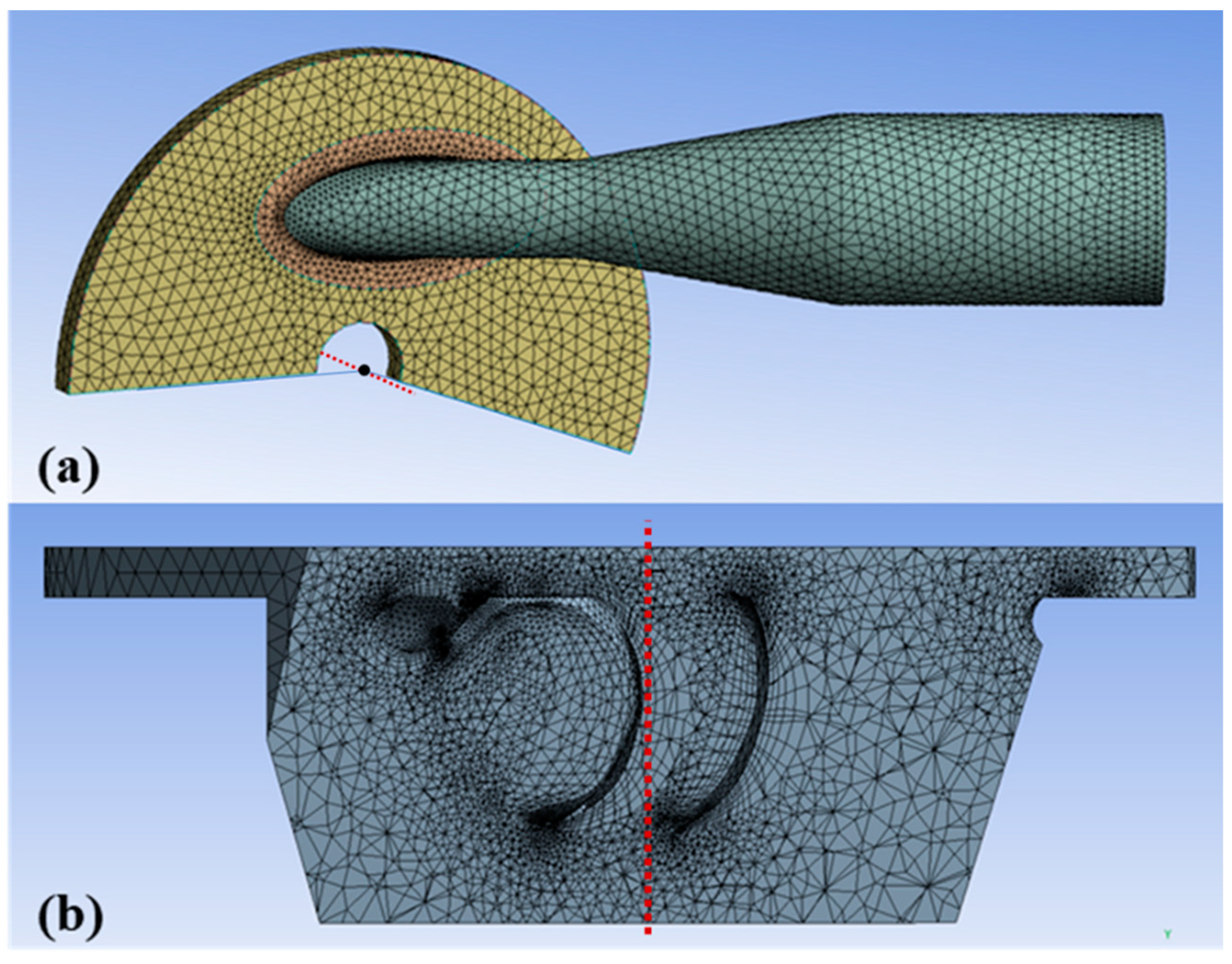
A two-part CFD model (generated from the CAD model of the turbine) was developed using ANSYS CFX, consisting of a rotating and stationary domain. The rotating domain comprised the two blades, the hub, and outer ring. The stationary domain represented the flow of water from the nozzle and its interaction with air. Figure 6 shows the separate meshes for the stationary and rotating domains (with the section shown taken through the central plane of the first blade).
The stationary domain consisted of three sections: first, a volume that represented the flow of water through and out of the nozzle; second, a “shroud” to represent the region of interaction between the stationary and rotating domain; and, finally, a cylindrical region surrounding the water flow as it passes through the shroud, representing the interaction between water and air. The majority of the stationary domain was meshed using a tetrahedral mesh. At the interface between the water flow volume and the surrounding cylinder, hexahedral elements were used, enabling finer control of the inflation layers at the air–water interface.
The rotating domain was a cylindrical wedge that represented the free space around the two blades, hub, and outer ring of the turbine runner. Additionally, it included a top shroud section to interface with the stationary domain. The rotating domain was meshed in a number of stages: An octree mesh was generated for the entire domain with higher mesh density specified for the regions surrounding the trailing and leading edges of the blade. Increased inflation layers and reduced mesh size were also specified for the surfaces of the blade, where the torque was measured. The octree mesh was converted to a Delaunay mesh with smoothing applied to elements where the orthogonal quality of elements was less than 0.4. Subsequently, the mesh was manually edited to improve the orthogonal quality for specific poor elements, and prism layers were added to the blade surfaces. A final stage of smoothing was used to remove bad quality elements throughout the entire mesh.
Table 2 lists the boundary conditions that were applied to the boundaries of the stationary and rotating domains and the interfaces between them. Despite the periodic nature of the turbine’s operation, periodic boundary conditions were not used. In this case, the turbine was driven by a single jet of water impinging on the blades. Within the model, this was modelled as (equivalent to) the runner rotating through a stationary jet. Unlike a reaction-type turbine, where the runner is submerged and the blades are continuously interacting with the fluid, for the impulse-type Turgo turbine, the interaction only occurs as the blades are passing through the jet. Therefore, as the blades do not experience a constant hydrodynamic interaction, periodic boundary conditions were not used.
Several features of the imported turbine provided the input parameters for the CFD simulation. Firstly, the upstream valve could be used to vary the flow rate but its proximity to the nozzle would result in highly turbulent flow leaving the nozzle orifice. Instead, it was assumed that the turbine would always be operated with the valve fully open. Secondly, the position (i.e., pitch circle diameter) and geometry of the nozzle (i.e., the angle and internal diameter) would remain fixed. Thirdly, as the turbine’s control system was designed to maintain the rotational speed at the generator’s rated speed, the target rotational speed for the turbine was 1500 rpm.
In this study, the calculation of hydraulic efficiency, η, depended on the ratio of shaft power to the power of the jet entering the stationary domain. As previously described, the resultant torque for each blade passage was determined based on the torques on the inside and outside surfaces of subsequent blades. This resulted in the following calculation for the efficiency:
η = ω N ( T 1 + T 2 ) Q   p s
where ω is the rotational speed, N is the number of blades, T1 is the torque on the inside surface of the first blade, T2 is the torque on the outside surface of the second blade, Q is the volumetric flow rate at the inlet, and ps is the static pressure of the fluid at the inlet to the stationary domain. All of these terms (with the exception of the number of blades) were extracted from ANSYS CFX.
A mesh convergence study was used to determine the mesh sizing required to generate acceptable results. Table 3 presents the results of the study. The results of the fine mesh were considered as the reference point; therefore, its normalised efficiency was 100%. The efficiency achieved with the coarse mesh was compared relative to this baseline. The close agreement (difference of 0.09%) of the normalised efficiencies achieved with the two meshes indicated that for the purposes of this study, where the blades designs would be compared to one another, the coarse mesh was acceptable.

4. Results

4.1. Initial Configuration

The initial study evaluated the best efficiency point (BEP) for the imported turbine. The first step was to evaluate the speed ratio: the ratio of peripheral jet velocity to the velocity of the runner, at the point where the jet impacts. Therefore, with reference to the nomenclature used in Figure 3, the speed ratio, x, can be defined as:
x = u v I
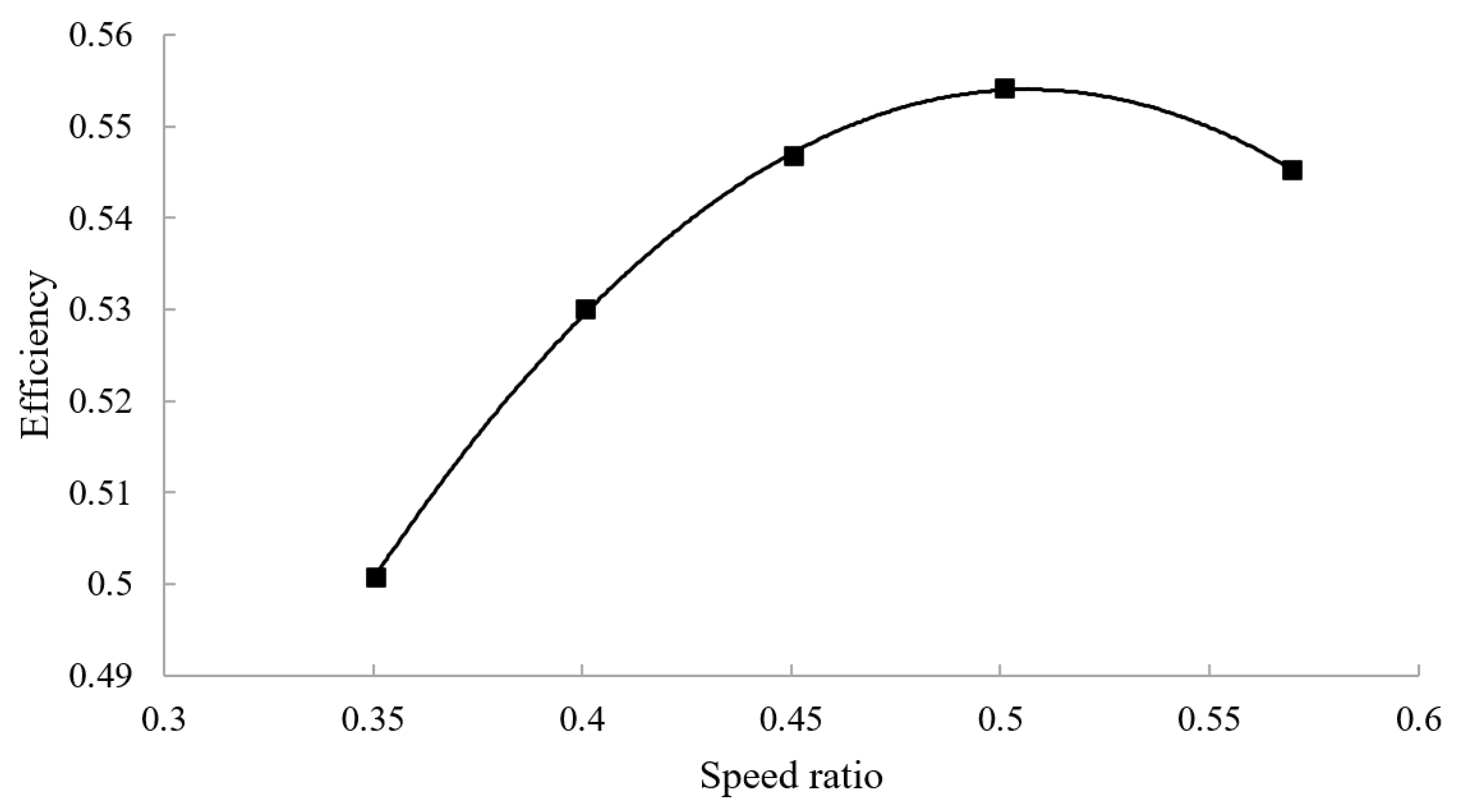
Using the manufacturer’s specified rotational speed of 1500 rpm, the simulations modelled varying speed ratios by changing the jet velocity, which is dependent on the head. Figure 7 shows the efficiency plotted against the speed ratio.
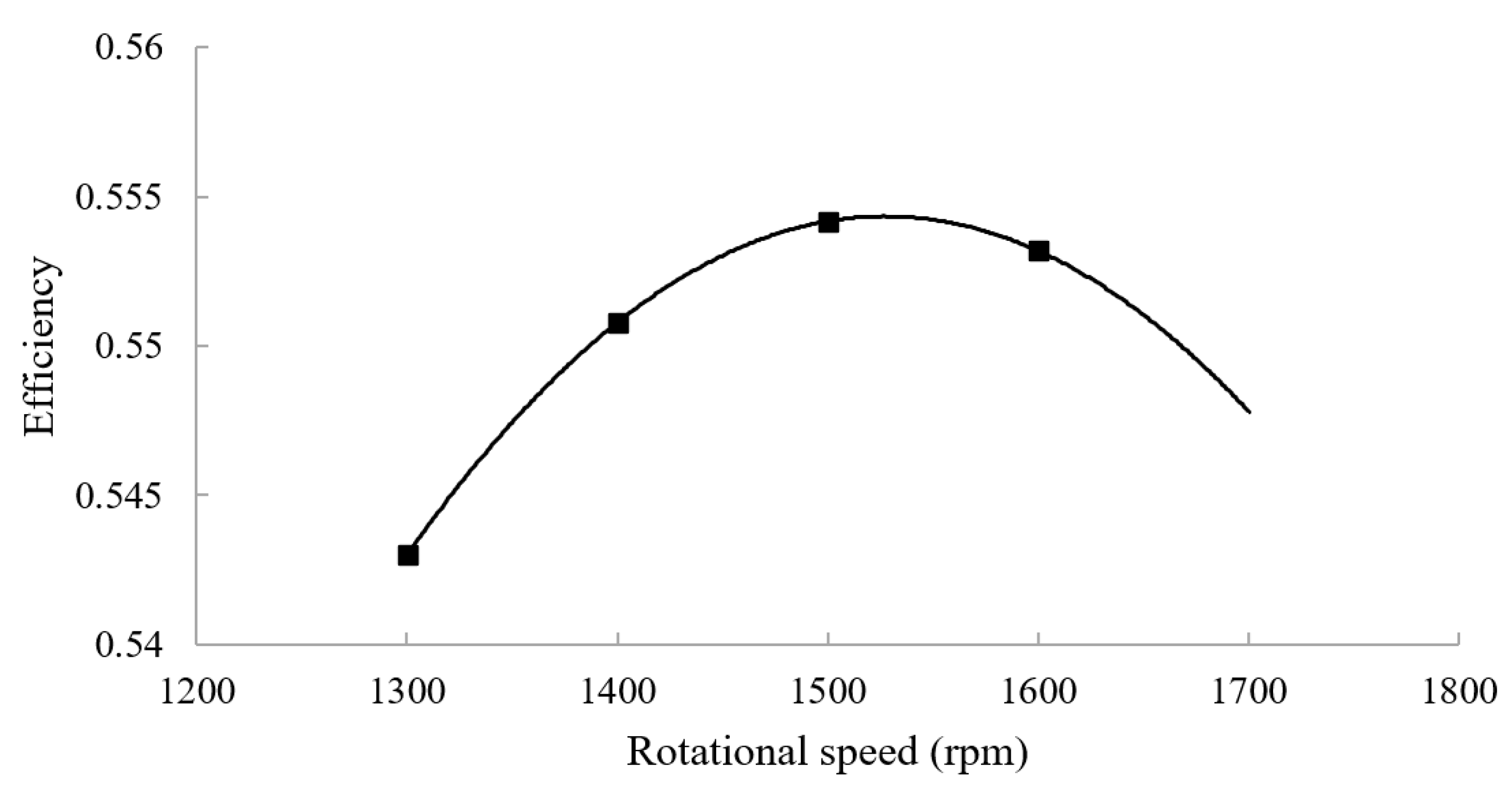
The highest value of efficiency occurred with a speed ratio of 0.5, which corresponds to a head of 14.7 m. For a jet angle of 22.5°, the theoretical speed ratio is 0.5 × cos (22.5°) = 0.46, though experimental testing often places the actual speed ratio slightly lower than the theoretical value [17]. It can be seen that the imported blade design has a relatively flat efficiency curve in response to varying speed ratio (a range of approximately 5%). Consequently, this means that on either side of the optimum speed ratio, a change in operational head of ±3 m results in a decrease in efficiency of less than 1%. By fixing the head to 14.7 m, it was possible to investigate the sensitivity of the efficiency to changes in the rotational speed. Figure 8 plots efficiency against rotational speed for a fixed head of 14.7 m. It can be seen that the BEP lies between 1500 and 1550 rpm. Evaluating rotational speeds of 1300 rpm, 1400 rpm, and 1600 rpm demonstrated that at these speeds the turbine maintained a similar efficiency, with a range of only 1.1%. For simplicity, it was assumed that the BEP was nominally 1500 rpm.
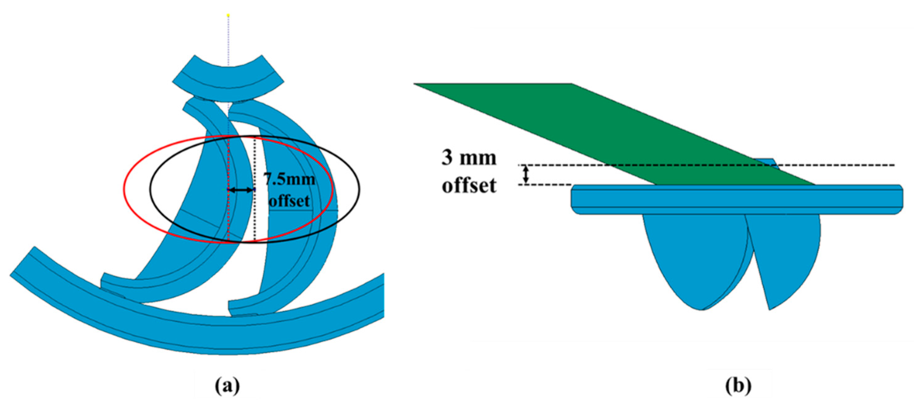
Each simulation maintained the original offset between the nozzle and runner that was measured from the imported turbine. By varying the offset, it was possible to optimise the position of the runner in relation to the jet. Figure 9 shows the original and optimised position of the jet. In Figure 9a, the original jet aim position can be seen in red. The oval represents the area of the jet as it impacts the top plane of the runner. In the original position, the center of the jet was colinear with front of the runner. From the starting position, the jet aim position was moved to the right (as shown in Figure 9a) with the black oval representing its new position. Movement of the jet aim position was equivalent to vertically moving the runner upwards, closer to the jet. An optimum position was identified that occurred with a horizontal displacement of 7.5 mm, equivalent to a vertical displacement of approximately 3 mm (as shown in Figure 9b).
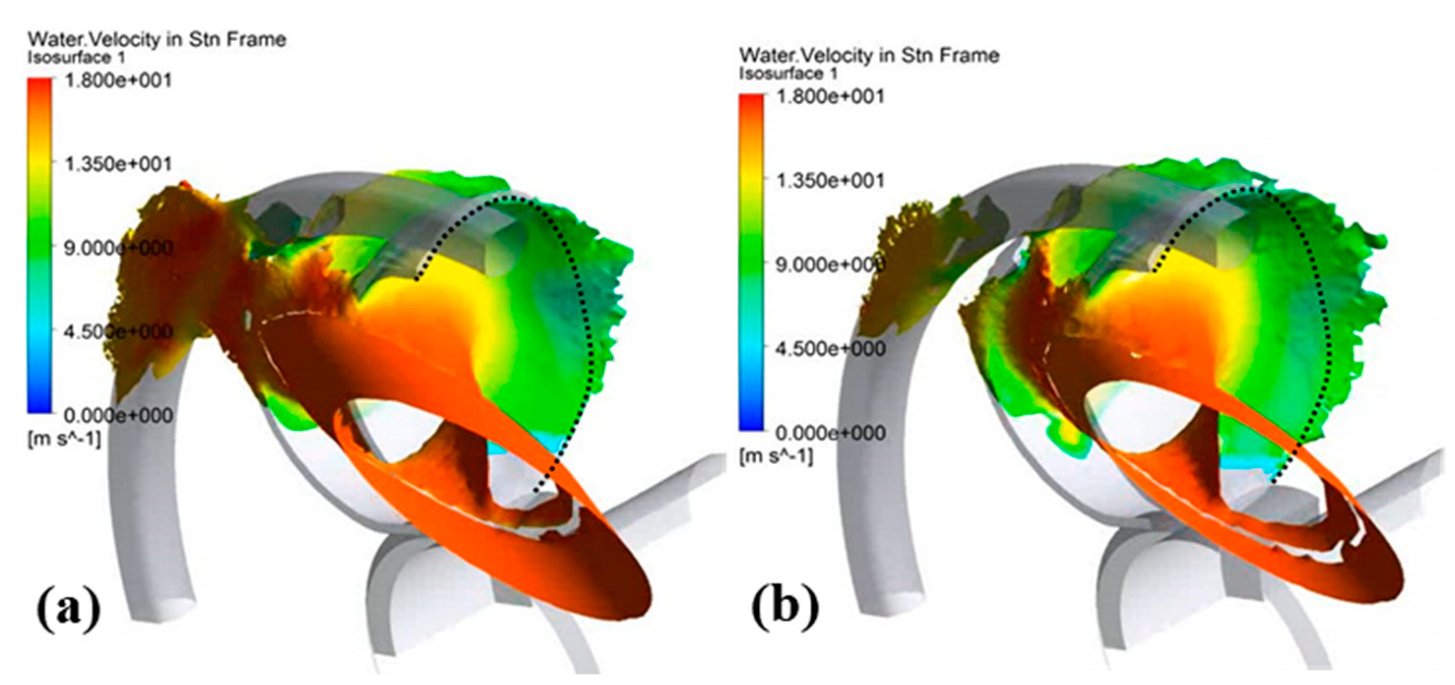
Figure 10 shows the simulation for the original runner position and the optimum position, an offset of 7.5 mm, at the same rotated angle. The legend in the figure represents the absolute velocity of the water flow and a dashed line is used to indicate the trailing edge of the two blades. Comparing the flow relative to this edge for Figure 10a,b, it can be seen that in the optimum position the flow was more evenly distributed across the total length of the edge, with a greater amount of flow having left the blade. In addition, the original runner position resulted in a significant amount of flow passing over the outer ring. In the optimum position, the center of the jet engaged lower in the blade, resulting in a more evenly distributed fluid film over the exit surface of the blade. It was found that, beyond an offset of 7.5 mm, further changes did not continue to increase the efficiency. Eventually, the position resulted in splitting of the jet, which negatively affected the performance.
From the initial study, the BEP was identified as occurring at a head of 14.7 m with a corresponding flow rate of 12.6 L/s. In addition, through variation of the offset between nozzle and runner, it was possible to identify a position for the imported runner that resulted in an increase in the efficiency from 56% to 69%. The value of 69% is close to the manufacturer’s predicted efficiency of 70%. The discrepancy between the initial value (56%) and the optimised value demonstrates the importance of correct setup of the turbine.
An initial study was used to develop a parametric representation of the 3D scanned blade. The initial CAD model of the imported blade consisted of multiple joined faces generated from the scanned point cloud. To aid design changes, a parametric model was developed by taking a section cut through the central plane of the blade and at 45° to this plane. Parametric sketches were developed to match the key dimensions of these section cuts. Figure 11 shows a section view of the blade through its central plane and identifies several key features. Similarly, a projected cut of the front face of the scanned blade was taken and a parametric sketch developed to match it. A loft between these three sketches created half of the blade, which was mirrored. By varying the parameters, the controllable model could be adapted and compared to the scanned model. The parametric values, which resulted in the most similarity between the models, were found by minimising the volumetric difference between the two. Using the BEP settings, the parametric blade was tested, achieving an efficiency of 69.5%, 0.5% higher than the efficiency achieved in the same conditions for the scanned blade. The improved flow passage through the blade, due to the removal of defects from the surface profile, was assumed to account for the marginal increase in efficiency of 0.5%.

4.2. Design of Experiments

Following establishment of this baseline and the development of a parametric model that represented the imported blade, a DOE study was used to explore simple changes to geometry that could be used to improve efficiency. Within the parametric model, it was decided to vary the height, depth, and width of the blade. Figure 12 shows these dimensions in relation to half of the blade and identifies the leading and trailing edges, where the flow enters and leaves the blade, respectively. The complete blade was formed by mirroring along the central plane, indicated by the darker grey face on the right hand of the figure. These changes were easy to implement in the parametric model, maintained the simple profile of the blade, and enabled assessment of how the geometry affects efficiency. A 23 factorial design was used whereby three factors were varied to maximum and minimum levels, resulting in a total of eight combinations [43]. This variation allowed the influence and interaction of the three factors upon a measured outcome to be explored. In this case, the maximum and minimum values corresponded to a variation of ±7% from the original dimensions of the height, width, and depth of the blade. As these dimensions were changed, the exit angle in the center of the blade (β in Figure 11) changed. The baseline parametric model had a central exit angle of 29°. A variation of ±7% was selected, as this resulted in a maximum change in this exit angle of 20°. It was expected that changes greater than this would not result in an improvement in performance: Too-shallow angles resulted in interference of the exit flow with the outside of the oncoming blades and too-steep angles resulted in a higher momentum of the exit flow, reducing the efficiency.
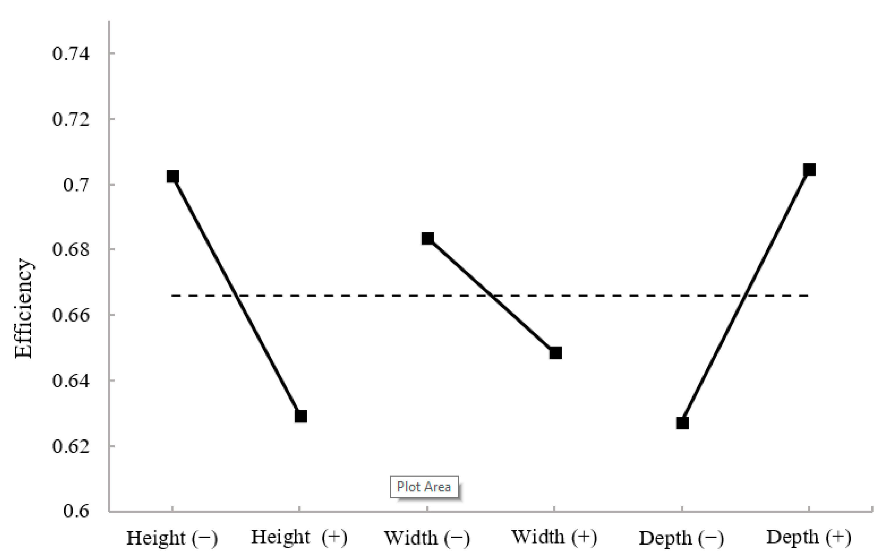
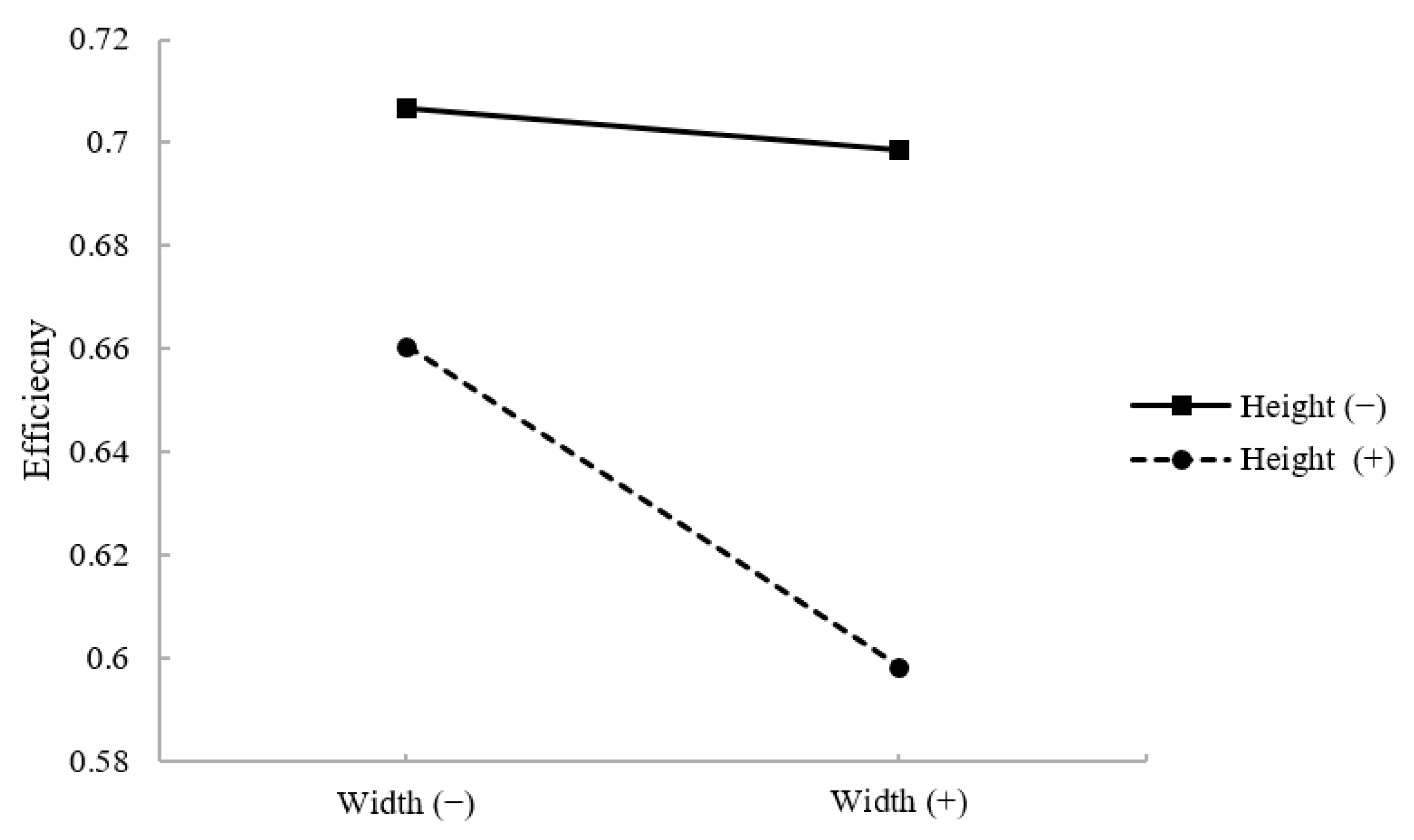
Figure 13 shows the main effects’ plots from the DOE study. It shows that the main effects of height and depth were strongest; all cases of minimising height and maximising depth led to an improvement in efficiency. These main effects were generally more significant than the interactions between factors. Figure 14 shows the most significant interaction, which was between the height and depth. This significance of this interaction was due to the low efficiencies achieved when height and depth were at +7% values. For all other cases, changes of width were not highly significant.
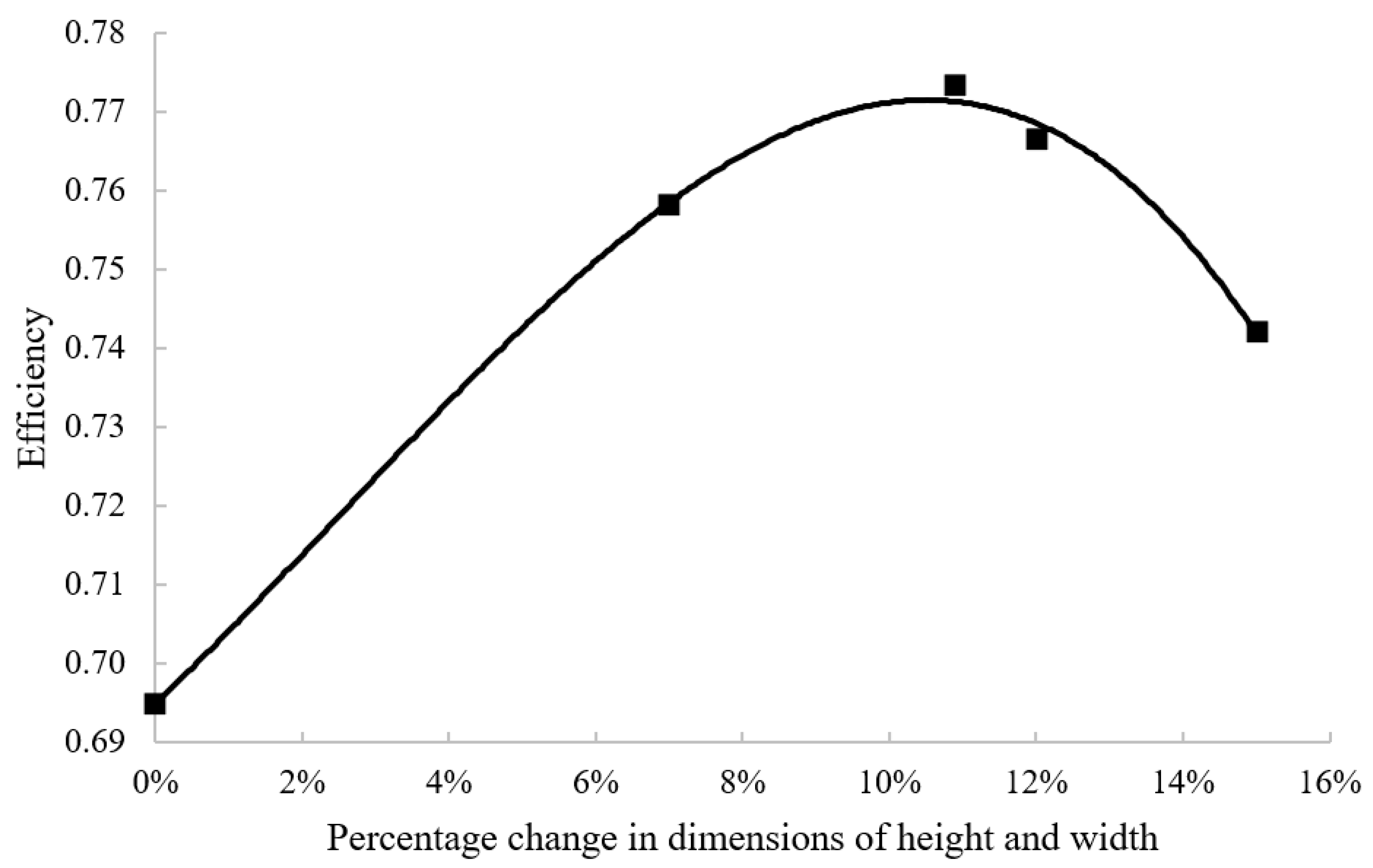
Consequently, the next set of runs explored the change in efficiency, with the width held at its original value. This allowed the blade to maintain a similar form while continuing to decrease the height and increase the depth. Figure 15 shows the results of simultaneously decreasing the height and increasing the depth while maintaining the original blade width. After changes of 7% and 12%, a quadratic relationship was assumed and indicated a best efficiency could be achieved with a ±10.9% change to depth and height. When simulated in CFD, this geometry, henceforth known as the “DOE blade” (using height = 0.891, width = 1, and depth = 1.109), resulted in an efficiency of 77.3%. Further runs with changes of 12% and 15% were used to test the validity of the relationship. With these additional points, the point representing a ±10.9% change was above the expected peak of the trendline.

4.3. Further Design Progression

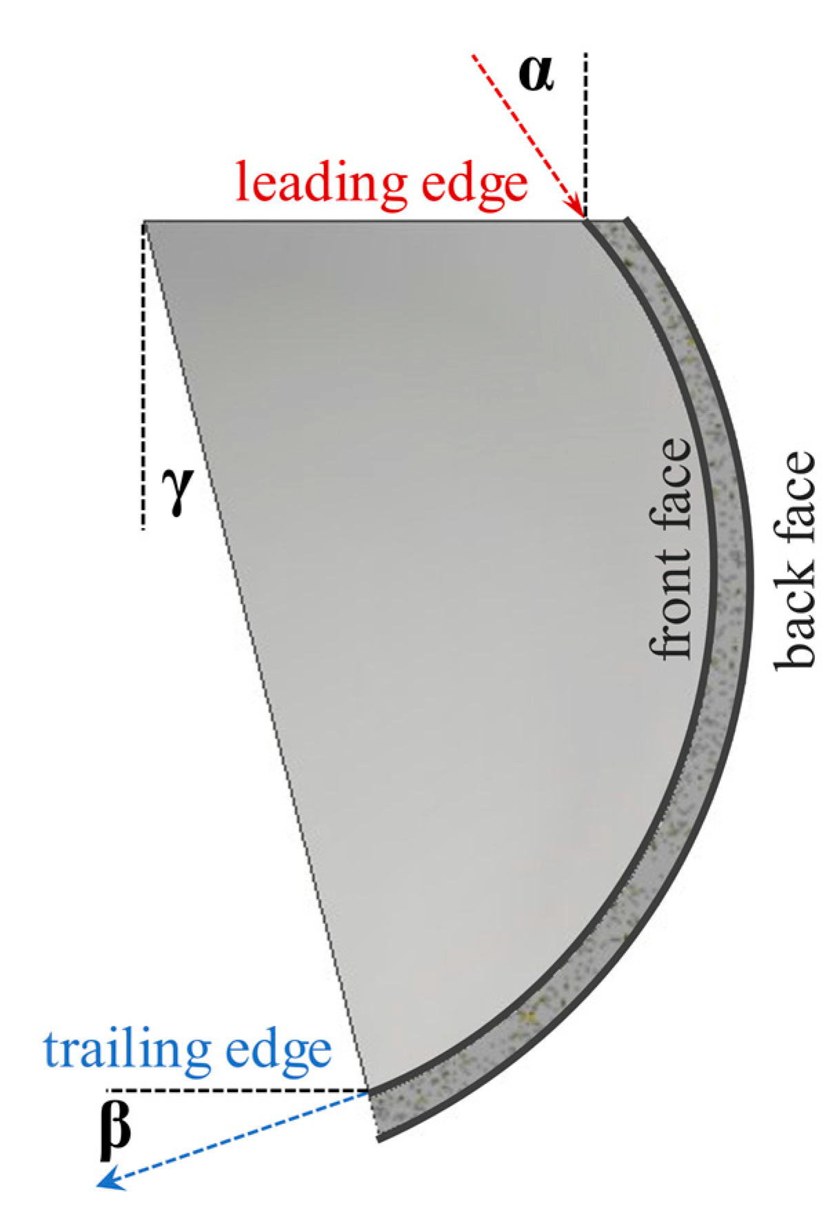
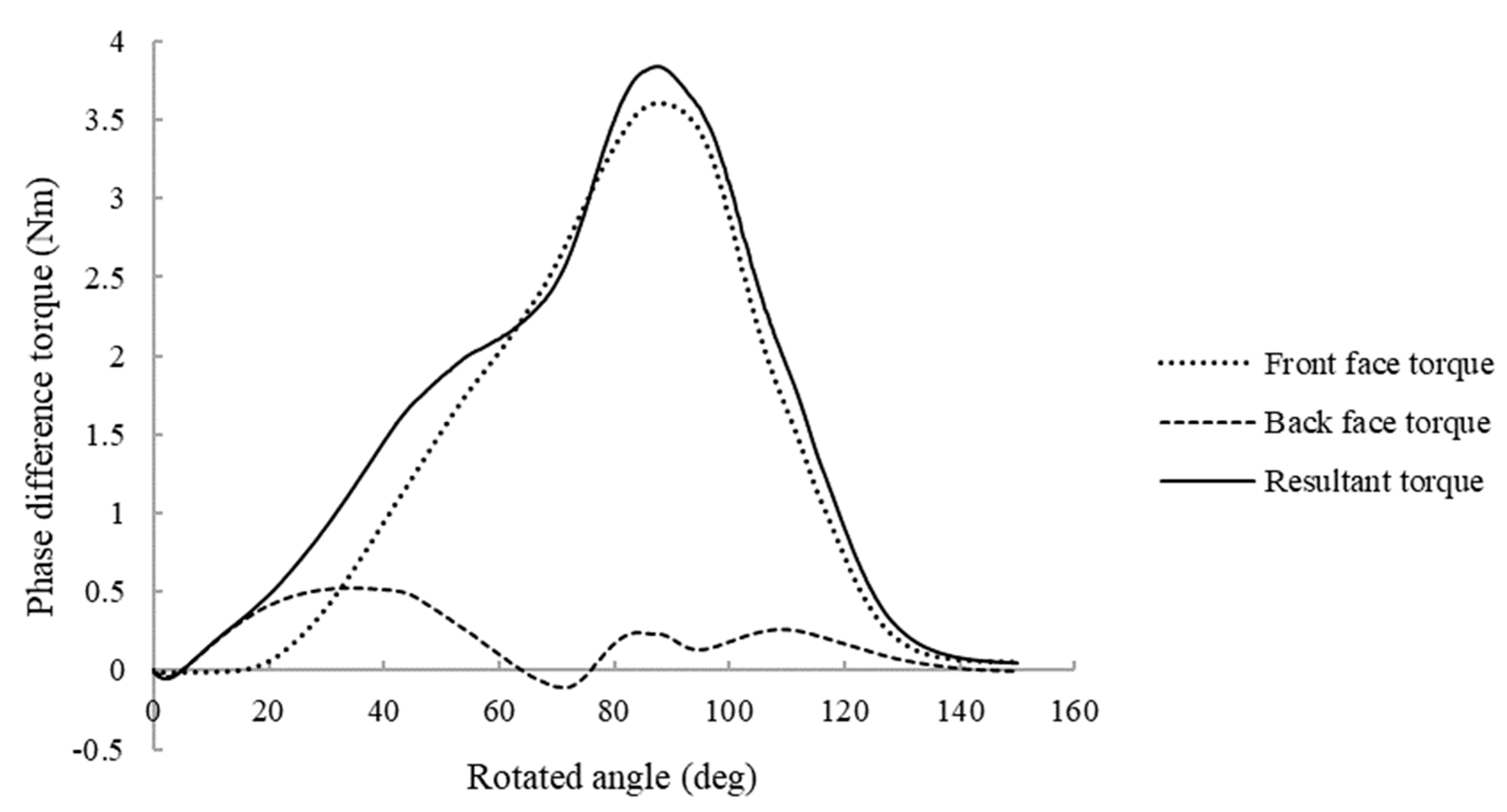
Following the DOE study, a number of geometrical changes were attempted in the pursuit of further improvements in efficiency beyond 77.3%. Table 4 summarizes these approaches. Typically, for each design change, a number of different rotating domains were generated, simulations were run, and the results were analyzed. The analysis of results depended on a combination of qualitative and quantitative methods. These combined modes of analysis were then used to inform further design changes. The qualitative method depended on the evaluation of CFD visualisations, both still and animated. An example is presented in Figure 10, a still taken from an animation. By comparing the visualisations generated for different designs, it was possible to identify blade designs that exhibited superior flow properties. The quantitative evaluation used the torque curves generated for each simulation. Figure 16 plots an example of the torque curve generated from a single simulation. The front face and back face torque values are shown in dashed lines, with the resultant torque (their sum) shown in a solid black line. The graphs plot the value of torque measured on each face as the blade rotates through 150°. For this blade, there was a defined peak at the angle when the greatest torque was generated. It can also be seen that between approximately 65° and 75°, a negative back face of torque was generated, which acted in the opposite direction to the runner’s rotation. This phenomenon often limited further improvement from the optimised DOE simulation.
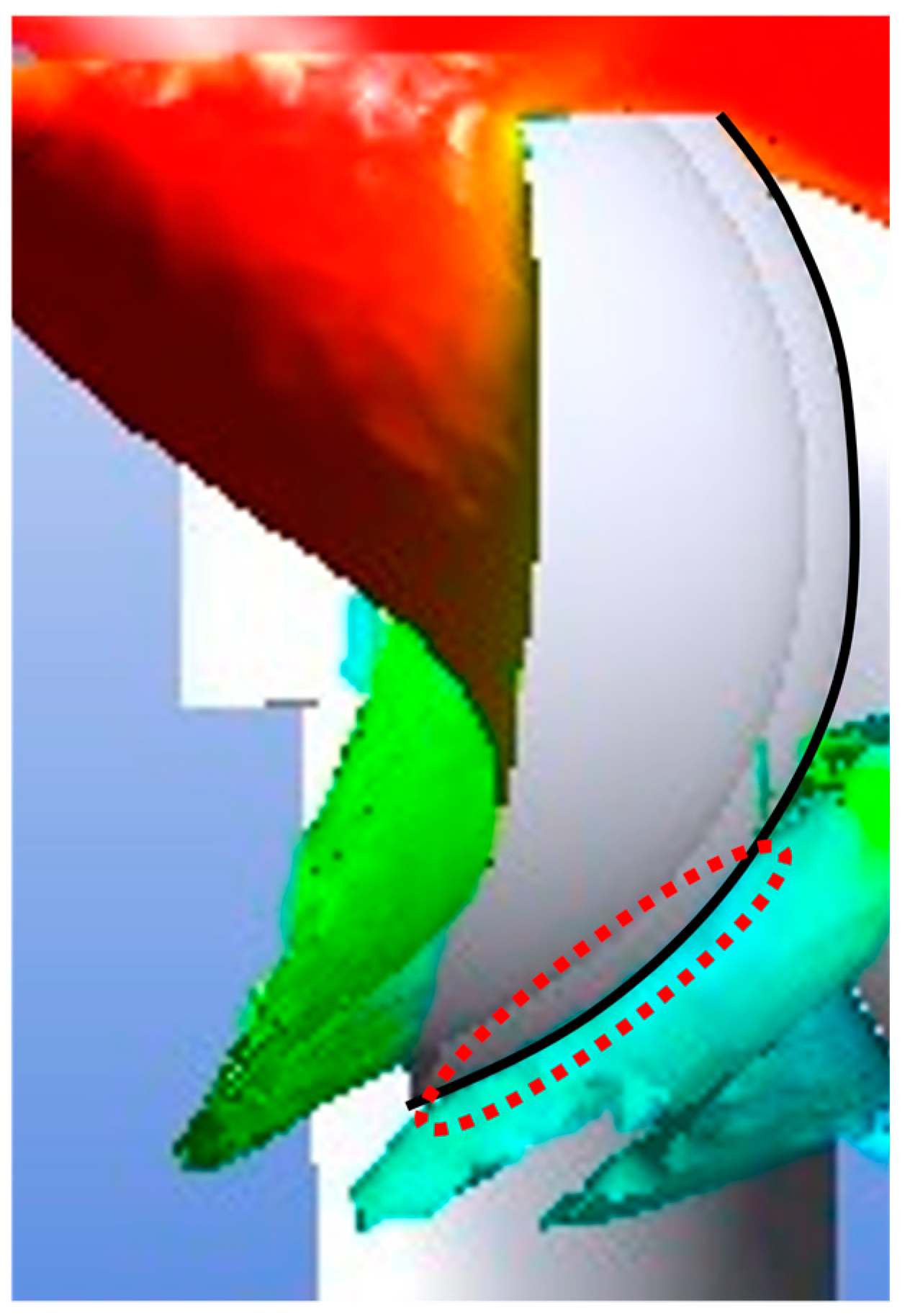
Physically, qualitative assessment demonstrated that this occurred when fluid leaving one blade interfered with the back face of the trailing blade, as shown in Figure 17. The solid, black line identifies the back face of the trailing blade whiled the dashed, red line indicates the area of interference. The flow leaving the inside of the blade impacted on the back face of the previous blade, creating a negative pressure. This resulted in a negative torque on the back face, opposite in direction to power-generating torque. The adaptation of the blade cut back angle (as described in Table 4) was unsuccessfully trialed as a solution to this problem.
Without further improvement through the geometrical changes described in Table 4, a further adaption was made to allow changes to the exit angles in multiple positions along the blade. The parametric model was adapted so that the exit angles could be adjusted along a number of vertical planes within the blade. Figure 18 shows the distribution of interstitial planes over half of the blade. On each of these planes, a controllable parametric sketch (similar to Figure 11) allowed the exit angles to be changed. At first, it was decided to attempt to direct more flow to the center of the blade. By implementing shallower exit angles in the planes closest to the outside edge, it was hoped more flow would exit through the effective “dip” at the center of the blade. In this simulation, there was an increase in the front-face torque; however, concurrently, the back-face torque decreased (to a larger negative value) due to more interference with the trailing blade.
In order to investigate the trade-off that occurred between exit angles that focused flow towards the center of the blade and those that tended to result in a more even flow film leaving the blade, two blades were generated with inverted distributions of angles going from the center to the outside edge. One blade had angles that increased from the center to the outside, while the other had angles that decreased from the center. The distribution of angles was identified from a simulation (within the DOE study) where there had been low interference, known henceforth as the LI blade.
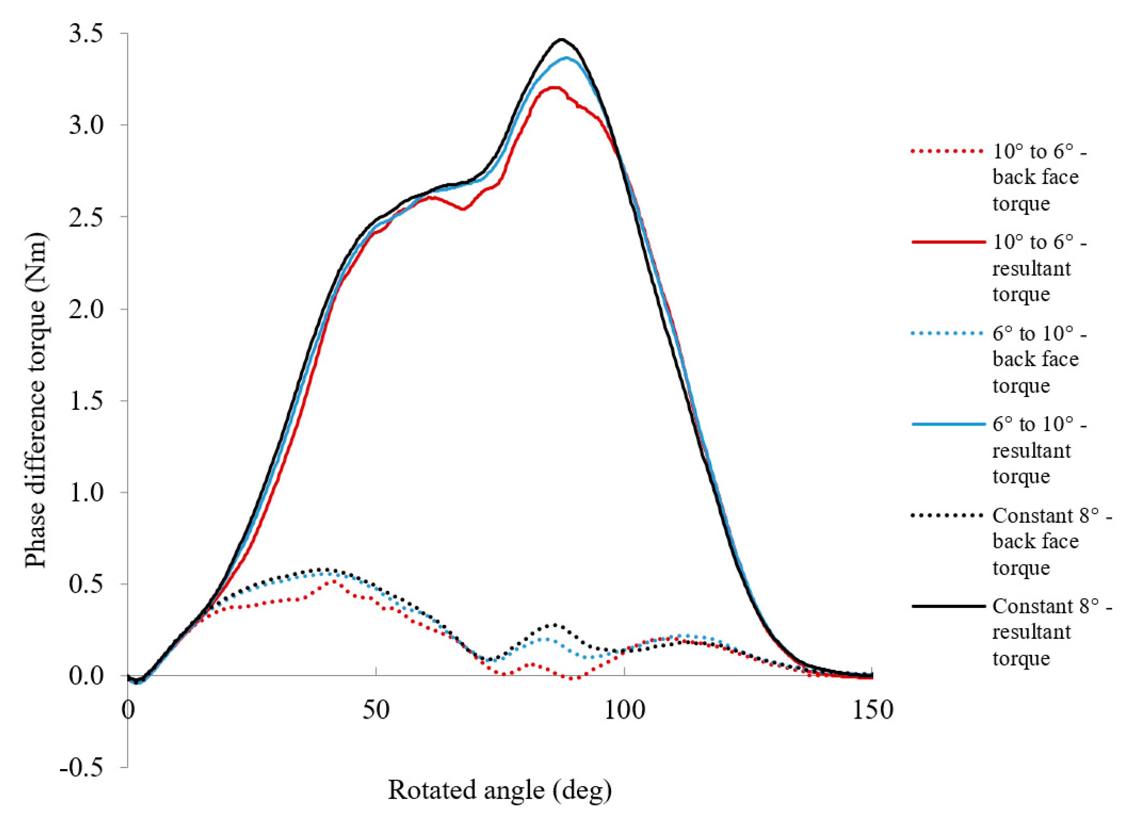
It was decided to examine using the height, width, and depth dimensions of the LI blade. Compared to the original blade, width and depth were 7% larger while height was 7% smaller. By using this blade, due to the decreased interference, there was a greater margin to optimise the exit angles without generating a negative torque. With this greater margin, two simulations were generated that both adopted the method of using the largest exit angle in the central plane to drive more flow towards the blade center. For one blade, the variation from center to outside was from 10° to 6° and resulted in an efficiency of 77.9%. The other, where angles varied from 12° to 8°, achieved 77.8%. For both runs, the change resulted in an increase in both the positive and negative torque. However, the positive torque was sufficient to result in an improvement of efficiency compared to the original LI simulation (75.7%). Figure 19 plots a comparison of further adaptions to the LI blade. The graphs plots the resultant torque (in solid lines) and the back face torque (in dashed lines) for three different blades. To combat the increased negative torque, the values of the higher efficiency run were inverted, placing the shallowest angle of 6° at the center. Comparing the blades with 10° to 6° from center to outside (in red) and with 6° to 10° (in blue), it can be seen that the blue back-face torque resulted in a higher resultant torque and a higher efficiency of 80.4%. A further change was implemented using a consistent 8° exit angle in all of the interstitial planes (in black lines on the graph). It was expected that this would provide more consistent exit velocities without causing substantial choking. The resulting front face torque profile was almost unchanged but the improved back-face torque resulted in an efficiency of 81.0%. Further runs were conducted using 7° and 9° constant exit angles but neither led to an improvement, suggesting an optimum had been found.

5. Discussion

The rationalised CFD approach applied in this paper resulted in an increase of efficiency from 55% to 81%. The final efficiency is comparable with the quoted efficiency of Thake’s micro-hydropower Pelton turbine, 82% [26]. An initial improvement from 55.4% to 69.0% was achieved by varying the jet-aim position alone. This demonstrated the importance of correctly installing machines or providing supporting information that allows users to do so [17]. Further improvement to efficiency was driven by a rationalised approach to CFD. Initially, the selection of casting as the production method led to the identification of several geometric restrictions to the blade design. Subsequently, adaptions to the parametric blade design were conducted in two main stages. Firstly, a DOE approach was used to vary major dimensions (height, width, and depth) of the Turgo blade, leading to an improvement of 6.2%. From the results, it was identified that the key trade-off was often between generating positive torque on the front face and minimising the negative torque on the back face. The second stage of adaption depended upon a finer adjustment of the parametric model. Controllable sketches dispersed throughout the blade allowed the exit angles to be varied in multiple locations along the blade’s trailing edge. Figure 20 shows key dimensions of the final blade. When compared to the original blade shown in Figure 5, it can be seen that the final blade is wider and deeper (internally) with a shallow exit angle.
Throughout the study, torque curves and visualisation were used to evaluate results. These two data sources allowed the effects of design changes to be identified through visual observation of flow phenomena and analysis of quantitative results. In general, in the design of runners for Turgo and other types of hydroturbines, the results indicated that the rationalised methodology could be applied in the following stages:
  • Identification of manufacturing restrictions to constrain design progression.
  • Development of a parametric model that allows variation of major dimensions and adjustment of critical minor dimensions at the trailing and leading edges.
  • Evaluation of CFD results based on visual simulations and quantitative data.
  • Incremental adjustment of the parametric model based upon analysis of the results.
When applied in this paper, a challenge was identifying parametric changes to overcome the generation of negative torque. Application of the methodology depended on evaluating particular flow phenomena and the ability to adapt the CAD model accordingly. Considering the existing work on Turgo blade design, the rationalised approach here reduced the number of simulations required while ensuring the blade could be manufactured locally. In [21], where 11 blade geometry parameters were varied, in excess of 1000 simulations were required to improve efficiency by 6%. It should be noted that the blade’s initial efficiency was higher than the baseline used here. In [22], the 3D potential flow method resulted in the development of a complex blade design that achieved an efficiency of 80.8%. In comparison, the efficiency achieved within this study is marginally higher while the changes to the geometry maintained the original simple blade profile.
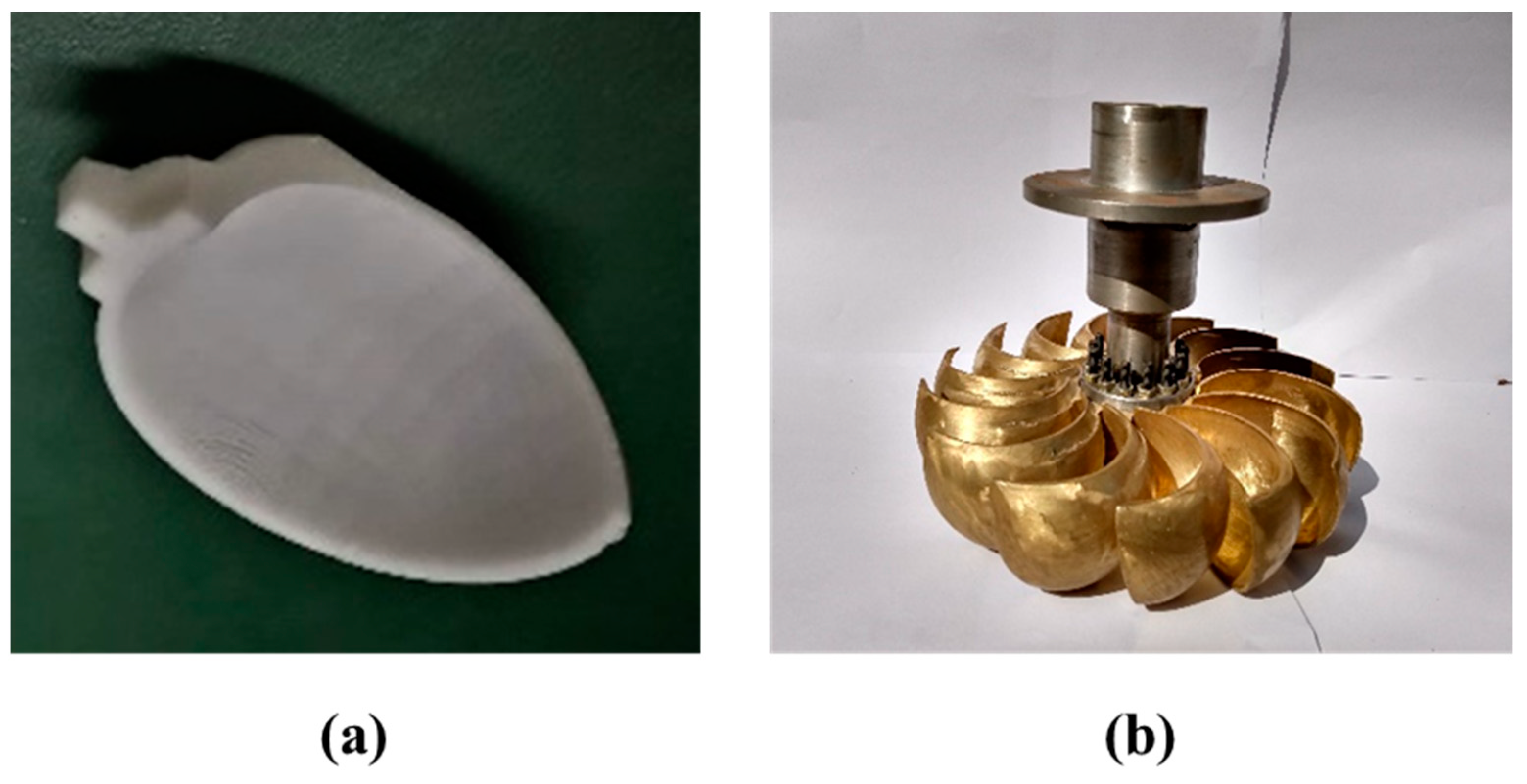
Following the design improvement in CFD, a 3D-printed pattern generated from the CAD model of the runner blade was used to sand cast blades in brass in Nepal. Figure 21 shows the 3D-printed pattern and the resulting finished runner. Its production demonstrated the final design was viable for local manufacture. There are multiple stages of further work. Firstly, experimental testing of the original and new runner is required to verify the CFD results. Assuming the experimental results confirm the reliability of the CFD simulation, the blade design can be scaled to higher rated powers. A key element of further work is identifying the optimum operational ranges of head and flow rate for the Turgo turbine, particularly in relation to the operating ranges of the Pelton and Crossflow turbines. Subsequently, the intention is to release a 3D CAD file to allow any user to access the runner design.
6. Conclusions

Despite several advantageous features and similarity to Pelton turbines, there currently exists no readily available design for local manufacture of Turgo runner blades. By digitally replicating an existing Turgo turbine, a parametric model was developed. Using CFD, it was identified that the efficiency of the existing turbine was highly sensitive to the jet offset position. Following configuration of the CFD model, a DOE study was used to identify height and depth of the runner blade as the key parameters governing the efficiency of the blade. Subsequently, a number of changes to the parametric geometry were implemented. It was found that the trade-off between exit velocities generating positive torque and causing interference with the trailing cup was a key consideration. To improve the control over the exit velocities, the ability to change the exit angles along the blade was introduced. An optimum geometry was found with a consistent exit angle of 8° along the trailing edge, ensuring a balance between optimum velocities and interference. Further adaptions to the blade thickness resulted in an eventual improvement from 69% to 81.0%. The resulting profile was manufactured in brass using sand casting. Further work will involve full embodiment of the design, manufacturing of a prototype in partnership with a local workshop, and hydraulic testing. The ongoing progression towards an open-source design will require the development of scaling tools and supporting information relevant to a range of contexts.

Author Contributions

Conceptualisation, J.B. (Joe Butchers) and S.B.; methodology, J.B. (Joe Butchers) and S.B.; software, J.B. (Joe Butchers), S.B. and G.A.; validation, J.B. (Joe Butchers), S.B. and S.W.; formal analysis, J.B. (Joe Butchers) and S.B.; investigation, J.B. (Joe Butchers) and S.B.; resources, S.B. and G.A.; data curation, S.B.; writing—original draft preparation, J.B. (Joe Butchers); writing—review and editing, S.B., S.W., J.B. (Julian Booker) and G.A.; visualisation, J.B. (Joe Butchers) and S.B.; supervision, S.W., J.B. (Julian Booker) and G.A.; project administration, J.B. (Joe Butchers); funding acquisition, J.B. (Joe Butchers) and S.W. All authors have read and agreed to the published version of the manuscript.

Funding

This research was funded through a PhD studentship from the Engineering and Physical Sciences Research Council, award reference 188052, and through Energize Nepal, project reference number ENEP-RENP-17-01.

Institutional Review Board Statement

Not applicable.

Informed Consent Statement

Not applicable.

Data Availability Statement

Data can be made available on request. The People, Energy and Environment Development Association intend to release the blade design information in due course.

Acknowledgments

The authors would like to thank the People, Energy and Environment Development Association and Nepal Yantra Shala Energy for their contributions to the research.

Conflicts of Interest

The authors declare no conflict of interest.

References

  1. Paish, O. Small hydro power: Technology and current status. Renew. Sustain. Energy Rev. 2002, 6, 537–556. [Google Scholar] [CrossRef]
  2. Dados, N.; Connell, R. The global south. Contexts 2012, 11, 12–13. [Google Scholar] [CrossRef] [Green Version]
  3. Meier, T.; Fischer, G. Assessment of the Pico and Micro-Hydropower Market in Rwanda; Entec AG: Zürich, Switzerland, 2011. [Google Scholar]
  4. Williamson, S.J.; Lubitz, W.D.; Williams, A.A.; Booker, J.D.; Butchers, J.P. Challenges Facing the Implementation of Pico-Hydropower Technologies. J. Sustain. Res. 2019, 2. [Google Scholar] [CrossRef]
  5. Butchers, J.; Cox, J.; Williamson, S.; Booker, J.; Gautam, B. Design for localisation: A case study in the development and implementation of a low head propeller turbine in Nepal. Dev. Eng. 2020, 5, 100051. [Google Scholar] [CrossRef]
  6. Khadka, S.S.; Maskey, R.K. Performance study of Micro-hydropower system in Nepal. In Proceedings of the International Conference In Sustainable Energy Technologies (ICSET), Kathmandu, South Asia, 24–27 September 2012. [Google Scholar]
  7. Williams, A.; Simpson, R. Pico hydro–Reducing technical risks for rural electrification. Renewable Energy 2009, 34, 1986–1991. [Google Scholar] [CrossRef]
  8. Pelliciardi, V. Overshot waterwheel to power an olive oil mill in Nepal. J. Appl. Water Eng. Res. 2015, 3, 157–165. [Google Scholar] [CrossRef]
  9. Benzon, D.S. The Turgo Impulse Turbine: A CFD Based Approach to the Design Improvement with Experimental Validation; Lancaster University: Lancaster, UK, 2016. [Google Scholar]
  10. Benzon, D.S.; Aggidis, G.A.; Anagnostopoulos, J.S. Development of the Turgo Impulse turbine: Past and present. Appl. Energy 2016, 166, 1–18. [Google Scholar] [CrossRef] [Green Version]
  11. Schumacher, O.; Austegard, A. RHL Cross Flow Turbine. Availabe online: http://www.remotehydrolight.com/CrossFlow.php (accessed on 7 December 2020).
  12. GrabCAD. Availabe online: https://grabcad.com/ (accessed on 7 May 2021).
  13. Thingiverse. Availabe online: https://www.thingiverse.com/ (accessed on 7 May 2021).
  14. Instructables. Availabe online: https://www.instructables.com/ (accessed on 7 May 2021).
  15. Benzon, D.S.; Aggidis, G.A.; Martin, J.; Scott, J.; Watson, A. State of the art & current research on Turgo impulse turbines. In Proceedings of the 13th Annual Africa Utility Week/Clean Power Africa, Cape Town, South Africa, 14–15 May 2013. [Google Scholar]
  16. Gaiser, K.; Erickson, P.; Stroeve, P.; Delplanque, J.-P.J.R.E. An experimental investigation of design parameters for pico-hydro Turgo turbines using a response surface methodology. Renew. Energy 2016, 85, 406–418. [Google Scholar] [CrossRef] [Green Version]
  17. Cobb, B.R.; Sharp, K.V. Impulse (Turgo and Pelton) turbine performance characteristics and their impact on pico-hydro installations. Renew. Energy 2013, 50, 959–964. [Google Scholar] [CrossRef]
  18. Gallego, E.; Rubio-Clemente, A.; Pineda, J.; Velásquez, L.; Chica, E. Experimental analysis on the performance of a pico-hydro Turgo turbine. J. King Saud Univ. -Eng. Sci. 2020, 33, 266–275. [Google Scholar] [CrossRef]
  19. Clarembaux Correa, J.L.; De Andrade, J.; Asuaje, M. A preliminary analysis of a Turgo type turbine CFD simulation designed with an integrated dimensional methodology. In Proceedings of the ASME 2012 Fluids Engineering Division Summer Meeting, Rio Grande, PR, USA, 8–12 July 2012; pp. 327–337. [Google Scholar]
  20. Williamson, S.J.; Stark, B.H.; Booker, J.D. Performance of a low-head pico-hydro Turgo turbine. Appl. Energy 2013, 102, 1114–1126. [Google Scholar] [CrossRef]
  21. Anagnostopoulos, J.S.; Papantonis, D.E. Flow modeling and runner design optimization in Turgo water turbines. World Acad. Sci. Eng. Technol. 2007, 28, 206–211. [Google Scholar]
  22. Clarembaux Correa, J.L.; De Andrade, J.; Noguera, R.; Croquer, S.; Jeanty, F.; Asuaje, M. Design procedure for a Turgo type turbine using a three-dimensional potential flow. In Proceedings of the Turbo Expo: Power for Land, Sea, and Air, Copenhagen, Denmark, 11–15 June 2012; pp. 2039–2052. [Google Scholar]
  23. Židonis, A.; Benzon, D.S.; Aggidis, G.A. Development of hydro impulse turbines and new opportunities. Renew. Sustain. Energy Rev. 2015, 51, 1624–1635. [Google Scholar] [CrossRef] [Green Version]
  24. Nechleba, M. Hydraulic Turbines: Their Design and Equipment; Artia: Prague, Czech Republic, 1957. [Google Scholar]
  25. Crewdson, E. Design and Performance of a New Impulse Water-Turbine. Min. Proc. Inst. Civ. Eng. 1922, 213, 396–407. [Google Scholar] [CrossRef] [Green Version]
  26. Thake, J. The Micro-Hydro Pelton Turbine Manual: Design, Manufacture and Installation for Small-Scale Hydro-Power; Practical Action Publishing: Rugby, UK, 2000. [Google Scholar]
  27. Eisenring, M. Micro Pelton Turbines; SKAT: St. Gallen, Switzerland, 1991. [Google Scholar]
  28. Chitrakar, S.; Solemslie, B.W.; Neopane, H.P.; Dahlhaug, O.G. Review on numerical techniques applied in impulse hydro turbines. Renew. Energy 2020, 159, 843–859. [Google Scholar] [CrossRef]
  29. Tiwari, G.; Kumar, J.; Prasad, V.; Patel, V.K.J.E.R. Utility of CFD in the design and performance analysis of hydraulic turbines—A review. Energy Rep. 2020, 6, 2410–2429. [Google Scholar] [CrossRef]
  30. Cromwell, G. What makes technology transfer? Small-scale hydropower in Nepal’s public and private sectors. World Dev. 1992, 20, 979–989. [Google Scholar] [CrossRef]
  31. Butchers, J.; Williamson, S.; Booker, J. Micro-Hydropower in Nepal: Analysing the Project Process to Understand Drivers that Strengthen and Weaken Sustainability. Sustainability 2021, 13, 1582. [Google Scholar] [CrossRef]
  32. Nakarmi, K.; Arter, A.; Widmer, R.; Eisenring, M. Cross Flow Turbine Design and Equipment Engineering. In MHPG Series Harnessing Water Power on a Small Scale; SKAT: St. Gallen, Switzerland, 1993; Volume 3. [Google Scholar]
  33. Butchers, J. Enabling Sustainable and Reliable Energy Using Locally Manufactured Micro-Hydropower Technology; University of Bristol: Bristol, UK, 2020. [Google Scholar]
  34. SUNECO Hydro Turbines. 1.5KW Hydro Turbine. Availabe online: https://www.micro-hydro-power.com/Micro-Hydro-Turbine-Power-Single-Nozzle-XJ25-1.5DCT4-Z.htm (accessed on 30 October 2020).
  35. Swift, K.G.; Booker, J.D. Manufacturing Process Selection Handbook; Butterworth-Heinemann: Oxford, UK, 2013. [Google Scholar]
  36. Smith, N. Motors as Generators for Micro-Hydro Power; Intermediate Technology Publications: London, UK, 1994. [Google Scholar]
  37. Perrig, A. Hydrodynamics of the Free Surface Flow in Pelton Turbine Buckets; EPFL: Lausanne, Switzerland, 2007. [Google Scholar]
  38. Barstad, L.F. CFD Analysis of a Pelton Turbine; Institutt for Energi-og Prosessteknikk: Trondheim, Norway, 2012. [Google Scholar]
  39. Židonis, A.; Aggidis, G.A. Pelton turbine: Identifying the optimum number of buckets using CFD. J. Hydrodyn. Ser. B 2016, 28, 75–83. [Google Scholar] [CrossRef]
  40. Jošt, D.; Mežnar, P.; Lipej, A. Numerical prediction of Pelton turbine efficiency. In Proceedings of the 25th IAHR Symposium on Hydraulic Machinery and Systems, Timişoara, Romania, 20–24 September 2010; p. 012080. [Google Scholar]
  41. Benzon, D. Using CFD in the analysis of Impulse turbines with a focus on the high capacity Turgo. In Proceedings of the 14th Annual Africa Utility Week/Clean Power Africa, Cape Town, South Africa, 13–15 May 2014. [Google Scholar]
  42. Židonis, A.; Panagiotopoulos, A.; Aggidis, G.A.; Anagnostopoulos, J.S.; Papantonis, D.E. Parametric optimisation of two Pelton turbine runner designs using CFD. J. Hydrodyn. 2015, 27, 403–412. [Google Scholar] [CrossRef]
  43. Antony, J. Design of Experiments for Engineers and Scientists, 2nd ed.; Elsevier: Oxford, UK, 2014. [Google Scholar] [CrossRef]
Figure 1. Visual representation of the restrictions imposed upon the blade in (a) plan view and (b) side elevation.
Energies 14 06250 g001
Figure 2. Diagram showing the interaction between the jet and the Turgo blade, adapted from [20].
Energies 14 06250 g002
Figure 3. Diagram showing the velocity triangles at the inlet and outlet of a Turgo blade.
Energies 14 06250 g003
Figure 4. Imported Turgo turbine set including (a) 1. induction motor, 2. electronic load controller, 3. turbine casing, and (b) 4. nozzle, 5. Runner, and 6. ballast heating element.
Energies 14 06250 g004
Figure 5. (a) The two-blade CAD model of the imported turbine runner. Note H, W, D, and PCD indicate the internal vertical height from the top surface to the trailing edge, the internal width, depth from the front face to the leading edge (parallel to the top surface), and the pitch circle diameter, respectively. (b) Section view through the central plane.
Energies 14 06250 g005
Figure 6. (a) Stationary domain and (b) rotating domain. For both domains, a red, dashed line indicates the rotational axis of the turbine.
Energies 14 06250 g006
Figure 7. Efficiency against speed ratio for the imported turbine.
Energies 14 06250 g007
Figure 8. Efficiency against rotational speed for the imported turbine when operating at a head of 14.7 m.
Energies 14 06250 g008
Figure 9. Optimization of the jet aim position shown in (a) plan view and (b) side elevation. The original jet aim position is shown in red with the optimised position in black.
Energies 14 06250 g009
Figure 10. Comparison of fluid velocity for the blade in its (a) original and (b) optimum position. In the figure, the legend values range from 0 (shown in blue) to 1.8 × 101 (red) with units of m/s. In the figure, the scientific notation of e as “multiped by 10 to the power of” is used, e.g., 1.8e+1 is equal to 1.8 × 101.
Energies 14 06250 g010
Figure 11. Section view of the blade in the central plane which identifies α, entry angle; β, exit angle; and γ, blade cut back angle.
Energies 14 06250 g011
Figure 12. Half of a blade with the height, width, and depth dimensions shown.
Energies 14 06250 g012
Figure 13. Main effects of height, width, and depth in the DOE study. The (−) and (+) refer to changes to the original dimensions of −7% and +7%, respectively.
Energies 14 06250 g013
Figure 14. Interaction between width and height in the DOE study. The (−) and (+) refer to changes to the original dimension of −7% and +7%, respectively.
Energies 14 06250 g014
Figure 15. Efficiency against the percentage reduction in height and increase in depth relative to the original blade dimensions.
Energies 14 06250 g015
Figure 16. Example of the torque curves generated from a single simulation.
Energies 14 06250 g016
Figure 17. An example of interference (indicated by the area bounded by the dashed red line) between exiting flow and the back face of the trailing blade (indicated by the solid black line).
Energies 14 06250 g017
Figure 18. Distribution of interstitial planes over half of the blade.
Energies 14 06250 g018
Figure 19. Resultant torque and back face torque against rotated angle for three variations of the “low interference” blade.
Energies 14 06250 g019
Figure 20. (a) The two-blade CAD model of the final runner. Refer to Figure 5 for a description of the indicated dimensions. (b) Section view with key dimensions in the central plane.
Energies 14 06250 g020
Figure 21. (a) The 3D-printed pattern and (b) assembled bolted runner with cast brass blades.
Energies 14 06250 g021
Table 1. Imported Turgo turbine specification [34].
CharacteristicValue (Units)
Rated head18–25 m
Rated flow8–10 L/s
Rated power1.5 kW
Generator rated speed1500 rpm
Pitch circle diameter0.1 m
Nozzle orifice internal diameter0.0307 m
Number of blades14
Jet inclination angle (to the horizontal)22.5°
Manufacturer’s predicted efficiency70%
Table 2. Boundary conditions of the CFD model.
Parent DomainBoundary Name (s)TypeBoundary DetailsFluid Values
Stationary domainJet inletInletFlow regime: Subsonic
Mass and momentum: Normal speed—jet velocity
Turbulence:
Medium (intensity 5%)
Viscosity ratio = 10
Air VF * = 0
Water VF = 1
Jet wallWallMass and momentum: Free slip wall-
Top of stationary domainOpeningFlow regime: Subsonic
Mass and momentum: Entrainment
Relative pressure value = 0 Pa
Turbulence: Zero gradient
Air VF = 1
Water VF = 0
Interface between domainsInterfaces between the domains and the water–air regionInterfaceMass and momentum: Conservative interface flux
Turbulence: Conservative interface flux
-
Rotating domainBlade surface, outer ring, and hubWallMass and momentum: No slip wall
Roughness: Smooth wall
-
Outlets from rotating domainOpeningFlow regime: Subsonic
Mass and momentum: Entrainment
Relative pressure value = 0 Pa
Turbulence: Zero gradient
Air VF = 1
Water VF = 0
* VF indicates volume fraction.
Table 3. Comparison of fine and coarse meshes.
MeshFineCoarse
Mesh sizing on blade surface1 mm2 mm
Number of cells1.4 million0.6 million
Normalised efficiency100%99.91%
Table 4. Attempted design changes and their outcomes.
DescriptionGeometrical ChangeJustificationOutcome
Extending middle sectionA larger section of constant blade profile was added to the central plane of the blade.To increase the proportion of the blade where entry and exit angles were at their assumed optimum. An increased amount of interference between exiting flow and the trailing blade, resulting in lower efficiencies.
Cut back angleThe angle between the blade’s inclined front face and the vertical plane was increased, angle γ in Figure 11.To minimise interference with the trailing blade by directing flow away from it.There was a reduction in interference and less negative torque was generated; however, torque generation on the front face was also reduced, leading to a lower overall efficiency.
V-cup shapeA v-shaped section was added in the central plane of the blade, reducing the length of the fluid path on the front face of the blade.To reduce the decrease in the velocity that occurs due to skin friction.There was a defined peak in the generated torque due to a higher exit velocity, but the overall total torque generated was lower, resulting in a decreased efficiency.
Publisher’s Note: MDPI stays neutral with regard to jurisdictional claims in published maps and institutional affiliations.