1. Introduction
Viktor Kaplan was born on 27 November 1876 in the Austrian town of Mürzzuschlag into the family of an Austrian railway official. After graduating, he enrolled at a Viennese university in the field of machine and diesel engine construction. In 1900, he completed a year of military service in the Austrian Navy in Pula and then worked for two years at the Ganz & Comp engineering plant in Löbersdorf near Vienna where he worked on the development of an internal combustion engine. In 1903, he joined the Department of Machine Science and Mechanical Engineering in the German Technical University in Brno. Very quickly, he fully devoted himself to scientific work on the rapidly developing issue of water engines [
1]. His goal was to improve the efficiency of the Francis turbine used at low heads and variable flow rates. He worked on this task from 1910. As a result, he concluded that the current design of the Francis turbine could not meet those requirements and therefore came up with his own solution. That consisted of a new concept of the propeller shape of the impeller. Thus, the original radiaxial flow rate was changed to a solely axial one. Furthermore, Kaplan reduced the number of impeller blades and made them adjustable so that the change in inclination allowed the best possible adaptation to the changing conditions. This made the Kaplan turbine suitable also for fluctuating heads and flow rates, and the increase in speed allowed a direct connection of the turbine to the generator without a gearbox.
Viktor Kaplan’s first patent, “Laufschaufelregelung für schnellaufende Kreiselmaschinen mit Leitvorrichtung…” (“Adjustment of the impeller blades of a high-speed machine”), dates from 1913 [
2]. In this context, it needs mentioning that Kaplan took care of the entire patent agenda on his own. This, together with the work on the development of a new turbine and, at the same time, a new theory for its construction, resulted in his physical and mental exhaustion of which later Kaplan fell seriously ill. In addition to his health problems, the first troubles with cavitation in his turbines appeared. These troubles provoked attacks from opponents especially from among the manufacturers of competing Francis turbines, which resulted in protracted lawsuits. In the end, the Kaplan turbine came out with a definitive victory.
2. Francis Turbine
At the time, the energy use of rivers with smaller heads and variable flow rates was necessary; the existing Francis turbines were unsuitable for such conditions. All the designers, and initially Kaplan as well, proceeded in the direction indicated by the then generally accepted one-dimensional theory [
3]. Admirable shapes of the blades were being created; however, they did not show a good efficiency in laboratory tests [
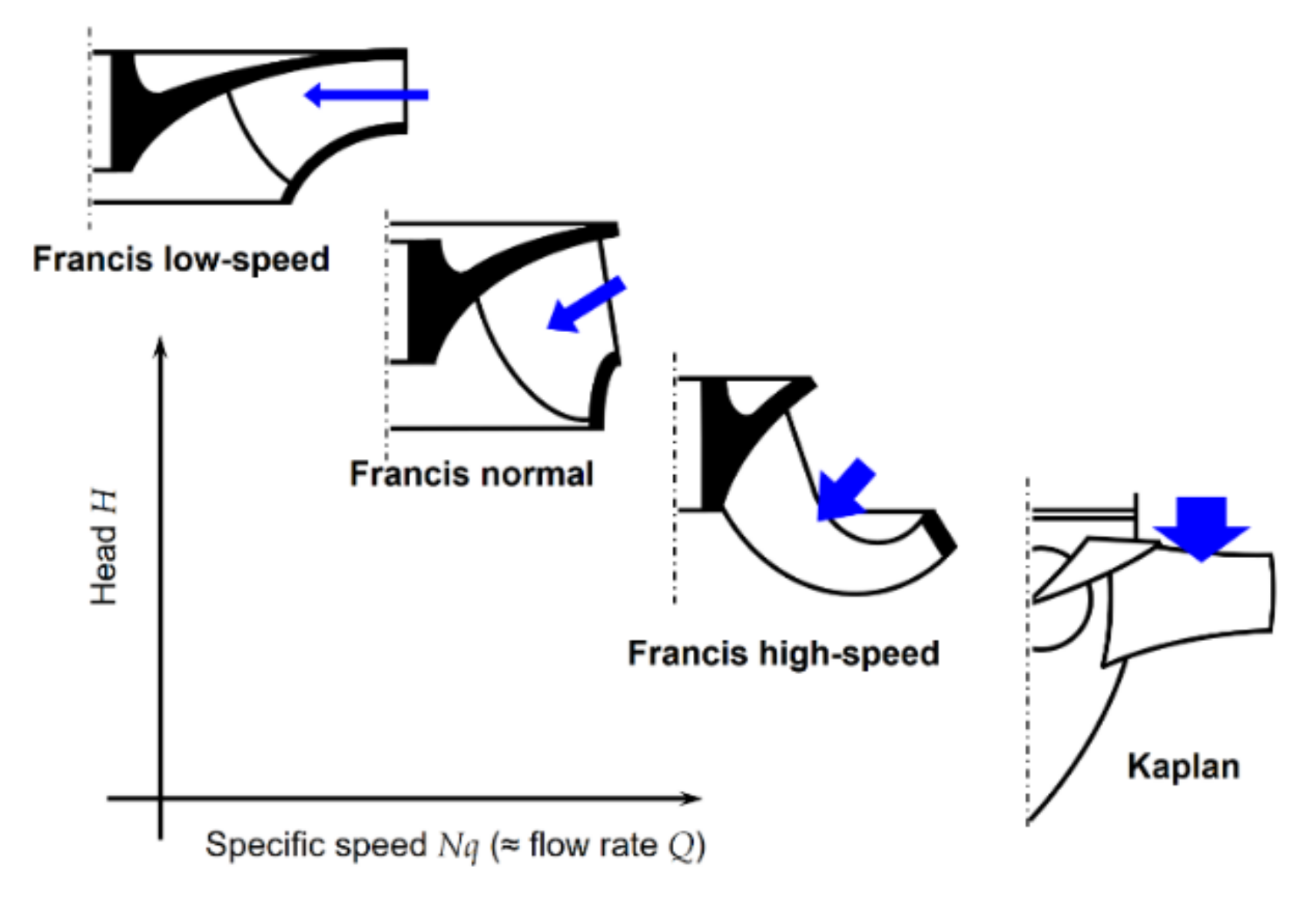
4]. The basic idea of the shape development of a specifically high-speed turbine impeller is illustrated by the diagram in
Figure 1.
This figure shows the impeller shapes of Francis turbines arranged by a specific speed. For greater clarity, it is plotted in the coordinate system head–specific speed (or flow rate). In the upper left corner, an impeller for the highest heads and lowest flows at the same time is depicted. The profile of such an impeller is narrow with a small flow area. The blue arrow indicates the hydrotechnic potential; its length corresponds with the head, H, and the width to the flow rate, Q. With a decreasing head and an increasing flow rate, the impeller profile gradually widens and the flow area increases. The lowest heads together with the highest flow rates then correspond with the open shapes of the impellers. From there, it is only a step to the impellers with a solely axial flow rate, which is embodied by the Kaplan turbine.
3. Impeller Innovation
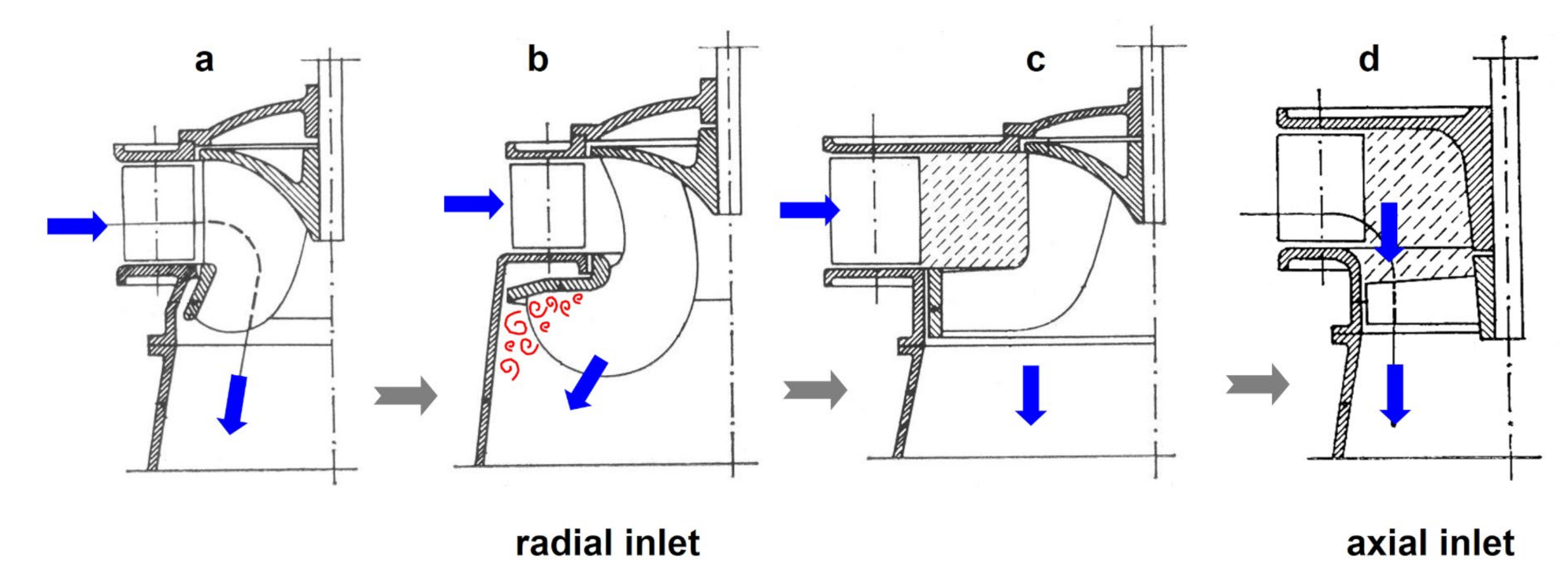
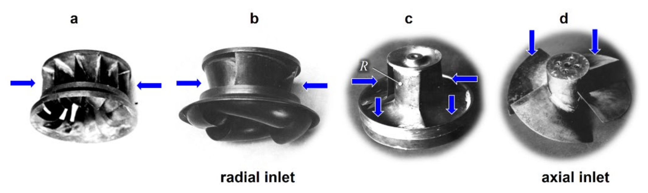
Kaplan’s own procedure can be followed in the diagram of the development series of his impellers in
Figure 2 and also in the photographs in
Figure 3. It is worth remembering that his goal was to increase the efficiency of the Francis turbine. From the left in
Figure 2, there is the development of the shapes of increasingly high-speed impellers to meet the requirements for a low head and changing flow rate. However, the gradually opening shape of the impeller resulted, at a certain moment, in the tearing of the liquid from the surface of the blades (see
Figure 2b) and thus a hydraulic loss with a rapid efficiency decrease [
4].
This moment of actual failure was the incentive for Kaplan to abandon the original concept of the Francis turbine. A new solution of the shape of blades was gradually arising, as shown in
Figure 2c (and also
Figure 3c). Here, the flow profile of the impeller was basically divided into two sections: one with mainly the axial flow and the other mainly with a radial flow. At the same time, a large bladeless space of free-flowing liquid was created between the guide blades and the impeller blades. This impeller already had much more favourable results in laboratory tests than the previous variants. The flow rate, efficiency and specific speed had increased [
3]. The experiments proved that the axially flowing section of the blades had a decisive influence. This led Kaplan to the idea of completely omitting the radial section (marked with the letter R in
Figure 3c) and giving the impeller a new shape where he also omitted the blade rim to reduce the friction losses. That resulted in the creation of an impeller with a solely axial flow, as presented in
Figure 2d. The photographs in
Figure 3 show the test impellers of the above development series, which Kaplan experimentally verified in his laboratory [
5].
4. Turbine Laboratory
Kaplan was not only an exceptional theorist but also an excellent experimenter who drew brilliant conclusions from his observations. For example, he noticed that a paper propeller rotated in a stream of warm air over a stove much faster than a paper spiral of a large area under the same conditions. Thus, he concluded that a reduced surface of the turbine impeller blades should have a similar effect. The laboratory experiments confirmed this assumption [
3,
4].
Kaplan can also be considered to be the founder of experimental research in this field. He invented peculiar aids for this purpose. Using bundles of hemp fibres in a draft tube, he examined the fluency of flow exiting the impeller. From these observations, he concluded a simple explanation of the principle of his turbine: “The impeller must usefully and as perfectly as possible stop the vortex caused to the water stream by the guide blades” [
4]. Kaplan also tracked the trajectory of water on the surface of the blades with tar added into the water, which later helped him investigate cavitation [
3,
5].
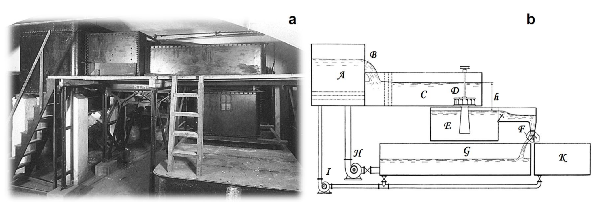
To get an idea of the conditions in which the turbine was created, it is worth presenting a few details about the laboratory used. Kaplan established it in 1910 in the basement of the school. The then Austrian Ministry of Education gave him only a small sum of money to equip it so he had to obtain most of the equipment himself. Under these circumstances, the laboratory did not provide much comfort. The turbine pit consisted of a wooden tank into which water was supplied from the upper, also a wooden, tank. Later, thanks to the Brno foundry Ignaz Storek, which manufactured and donated certain equipment to Kaplan, the wooden tanks were replaced with metal ones [
4]. The photograph in
Figure 4a shows the main part of the laboratory equipment and in
Figure 4b, there is a diagram of the arrangement of the test circuit [
6].
On the left side of the diagram, a water storage tank (A) was supplied by a pump (H). The water flowed from the tank through a measuring weir (B), which was used for measuring the turbine flow rate. The water then continued through the flow damper to the turbine pit, at the bottom of which the experimental turbine (D) was placed. The water flowed from the turbine through the draft tube into the lower tank (E). The head (h) was determined by measuring the height difference between the two water levels in two glass tubes with a ruler. The turbine shaft speed was measured with a hand-held speedometer. From the lower tank, water flowed through the rotary valve (F) into the reservoir. The rotary valve together with the tank (K) was used to calibrate the flow rate at the measuring weir. The calibration was performed as follows: after a quick rearrangement of the valve (F), the time required to fill the calibration tank—the volume of which was known—was measured by a stopwatch. An exact flow rate was calculated from the known volume or weight of the water and the time of the filling.
5. Experimental Turbine
A fundamental decision had to be made prior to the construction of the turbine laboratory: what the smallest possible dimensions of the experimental turbine without compromising its ability to be used for achieving sufficiently accurate and reliable results were. Kaplan eventually opted for a turbine with an impeller diameter of 184 mm [
3].
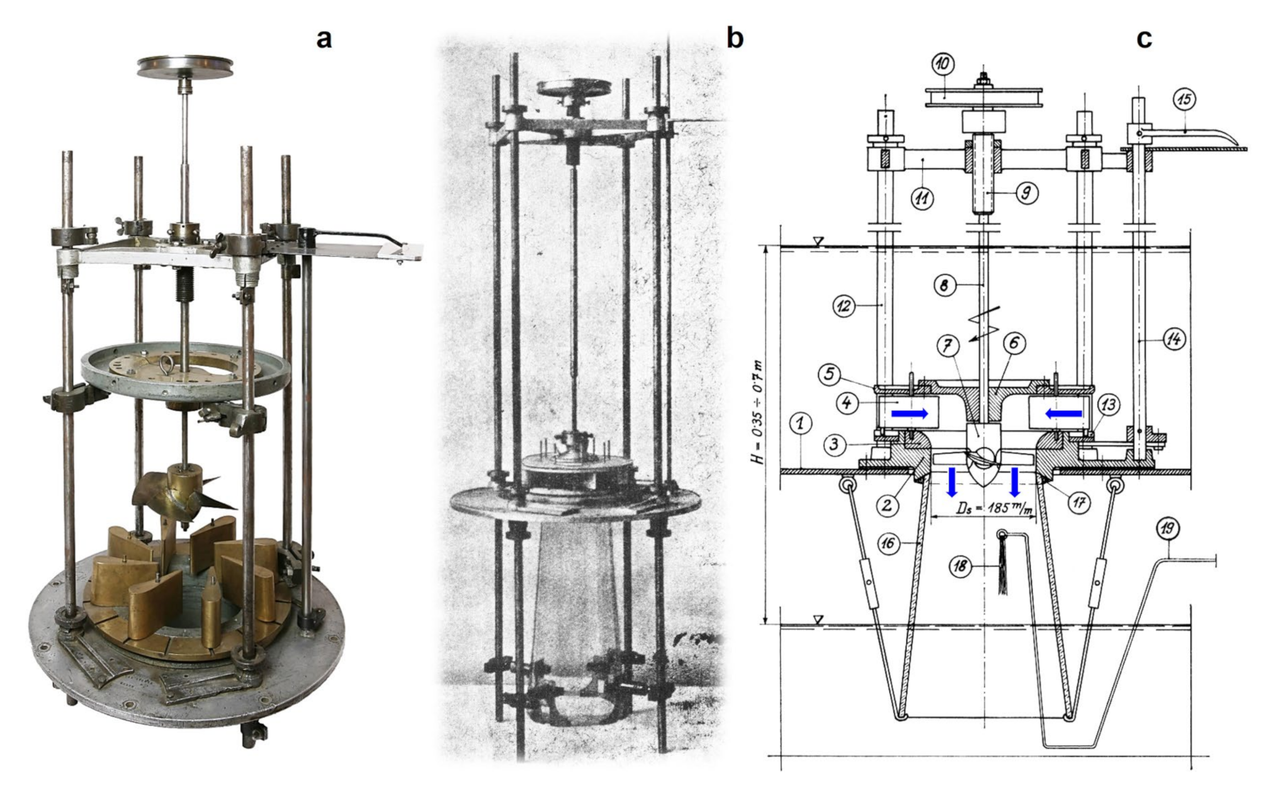
Figure 5a presents a photograph of the original Kaplan experimental turbine as it has been preserved. It is currently in the ownership of the National Technical Museum in Prague, being occasionally exhibited [
7].
Figure 5b shows a historical photograph of the complete turbine assembly including the glass draft tube [
6]. The diagram of the complete assembly is in
Figure 5c [
4]. It indicates the turbine location at the bottom of the pit where it operated with the heads of 0.35 to 0.7 m between the upper and lower tanks.
The water flowed radially into the impeller via the guide blades (4). Past the guide blades, the flow direction changed to axial. After passing through the impeller, water flowed into the draft tube (16). The draft tube was made of glass to make it possible to observe the flow exiting the impeller. A vortex-free outlet is a condition for an optimal turbine function, i.e., a smooth flow in the direction of the impeller axis. To investigate the flow, Kaplan used a thicker wire (19) inserted into a draft tube, at the end of which a bundle of hemp fibres (18) was attached. These fibres moved in the direction of the flowing water in the draft tube. As Kaplan himself stated, if it was possible to move the wire easily over the entire profile of the draft tube and the fibres moved in a smooth “combed” manner, the highest power and efficiency were measured on the turbine. If there was a vibration or jerking in places and the fibres were twisting wildly, it meant both a low power output and efficiency [
4]. Later, glass suction tubes were also used to observe cavitation on the bottom side of the impeller blades.
The turbine output was measured using a simple friction brake located on a disc (10) at the upper end of the impeller shaft. During the experiments, the peripheral force on the arm was measured indicating the torque on the turbine shaft [
4].
6. Experimental Verification
Testing new types of turbine impellers on models in laboratories was no longer a novelty at the time. Large companies performed such tests on models with an impeller diameter of around 700 mm so that the Reynolds number was high enough [
3]. Due to the low purchase and operating costs and the easy and cheap production of the models, Kaplan chose much smaller impeller dimensions; first with a diameter of 100 mm and later, after a reconstruction of the laboratory based on the experience gained, with a diameter of 184 mm. It turned out that this choice was extremely fortunate [
4]. Although the miniature size of the impellers was criticised by many experts as a serious shortcoming, it later proved to be an invaluable advantage; Kaplan’s laboratory made an experimental impeller in a single day. The blades were formed from sheet metal, soldered to the hub; a few hours later, the impeller was tested. All this was achieved at a small cost [
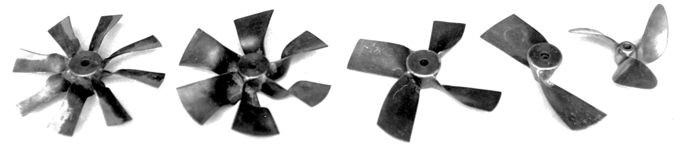
4].
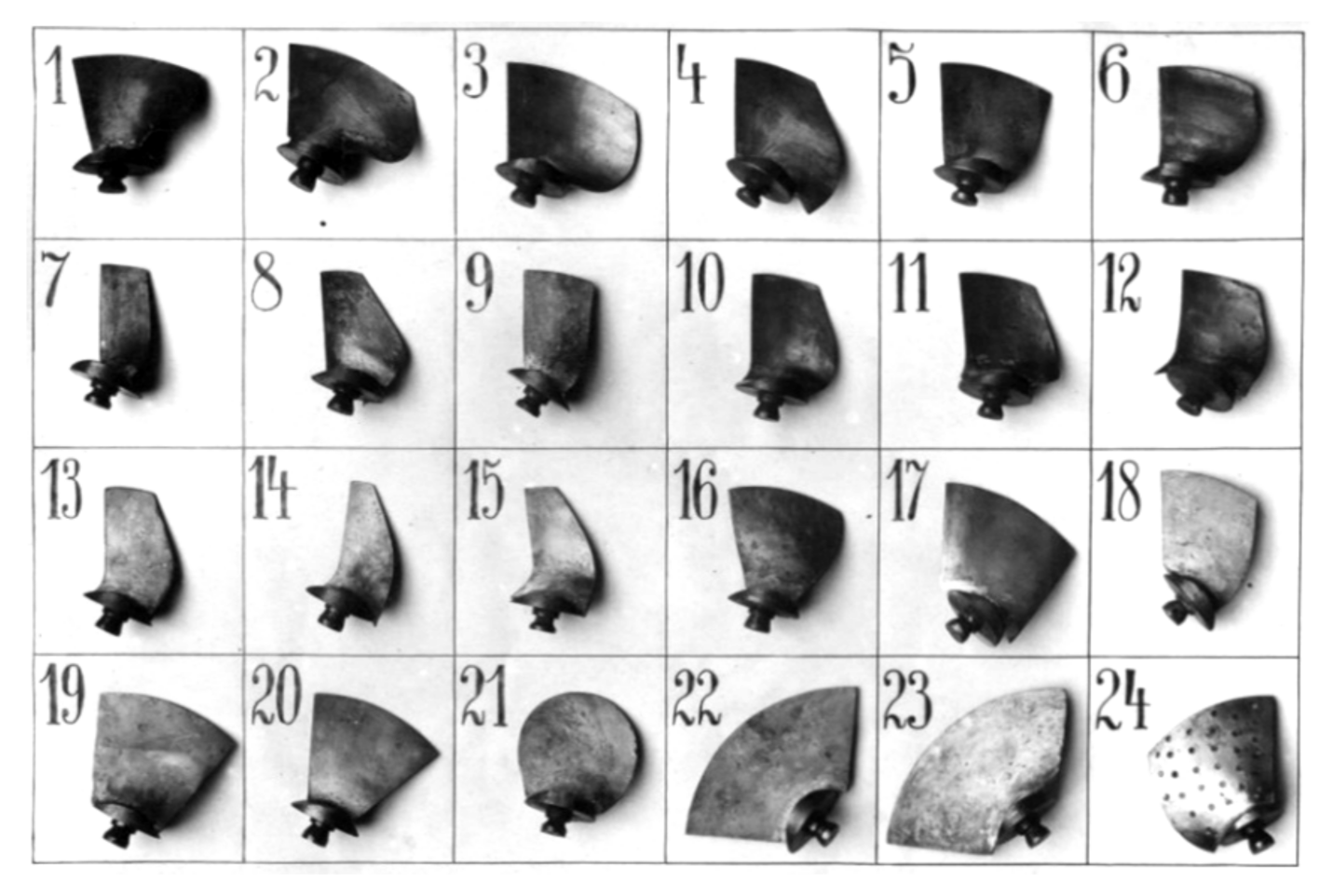
Figure 6 shows several impellers with fixed blades made in this way [
5].
From the innumerable tests, an impeller with a then unprecedentedly high speed at a high efficiency gradually emerged. However, it turned out that this turbine operated with a high efficiency only if a certain specific flow rate was set by the guide blades. If the flow rate changed, the efficiency decreased rapidly. It was also necessary to change the impeller blade angles to maintain the optimal efficiency, not just the output angles of the distribution blades, as is the case of regulation by the guide blades only. Kaplan solved the problem in an unheard of way at the time. He equipped the impeller with adjustable blades; adjusting them to the appropriate inclination ensured that the turbine adapted to different operating conditions. This concept created a completely new type of turbine. Each of the impeller blades was provided with a pin pivotally inserted into the hub. At this stage of the development, the blades were already cast in bronze. They were manufactured by the Ignaz Storek foundry in Brno, which significantly helped Kaplan [
8]. Several developmental types of rotatable blades are shown in
Figure 7 [
5].
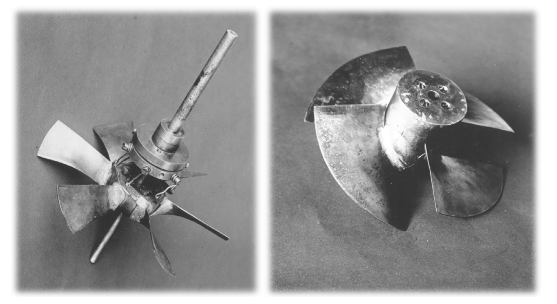
Two variants of hubs with different ways of mounting the rotatable blades are shown in
Figure 8 [
5]. It must be noted that, because of the maximum structural simplicity, the blades of the first test impellers were adjustable only at rest, not during operation.
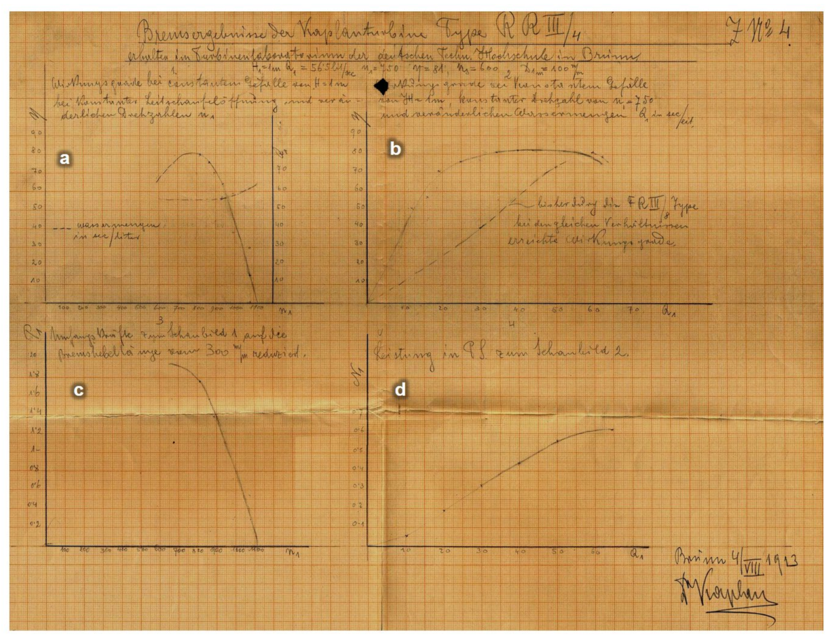
The results of the original performance tests are presented in
Figure 9 [
9]. The measured values were manually calculated and plotted onto graph paper. The signature of Professor Kaplan in the lower right corner and the date of the acquisition of the results (4/VIII 1913) guarantee the originality of the document. For better clarity, the accompanying comments on the individual graphs are translated in the description below the picture.
These are the results of the brake tests of the impeller marked RR III/4 at the parameters given in the legend. The most important is the diagram at the top right (
Figure 9b). It presents the flat course of efficiency with a varying flow rate (solid line), which resulted from the possibility of adjusting the impeller blades. The dashed line indicates the efficiency of the impeller FR III/8 with fixed blades, measured under the same conditions. Comparing these two curves shows a clear advantage in favour of Kaplan’s new impeller concept with an axial flow and adjustable impeller blades. Only in this way could water energy be used efficiently in localities with a highly variable hydrotechnic potential.
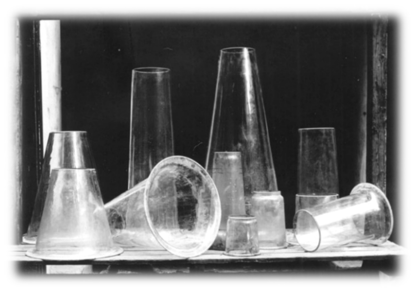
7. Draft Tube
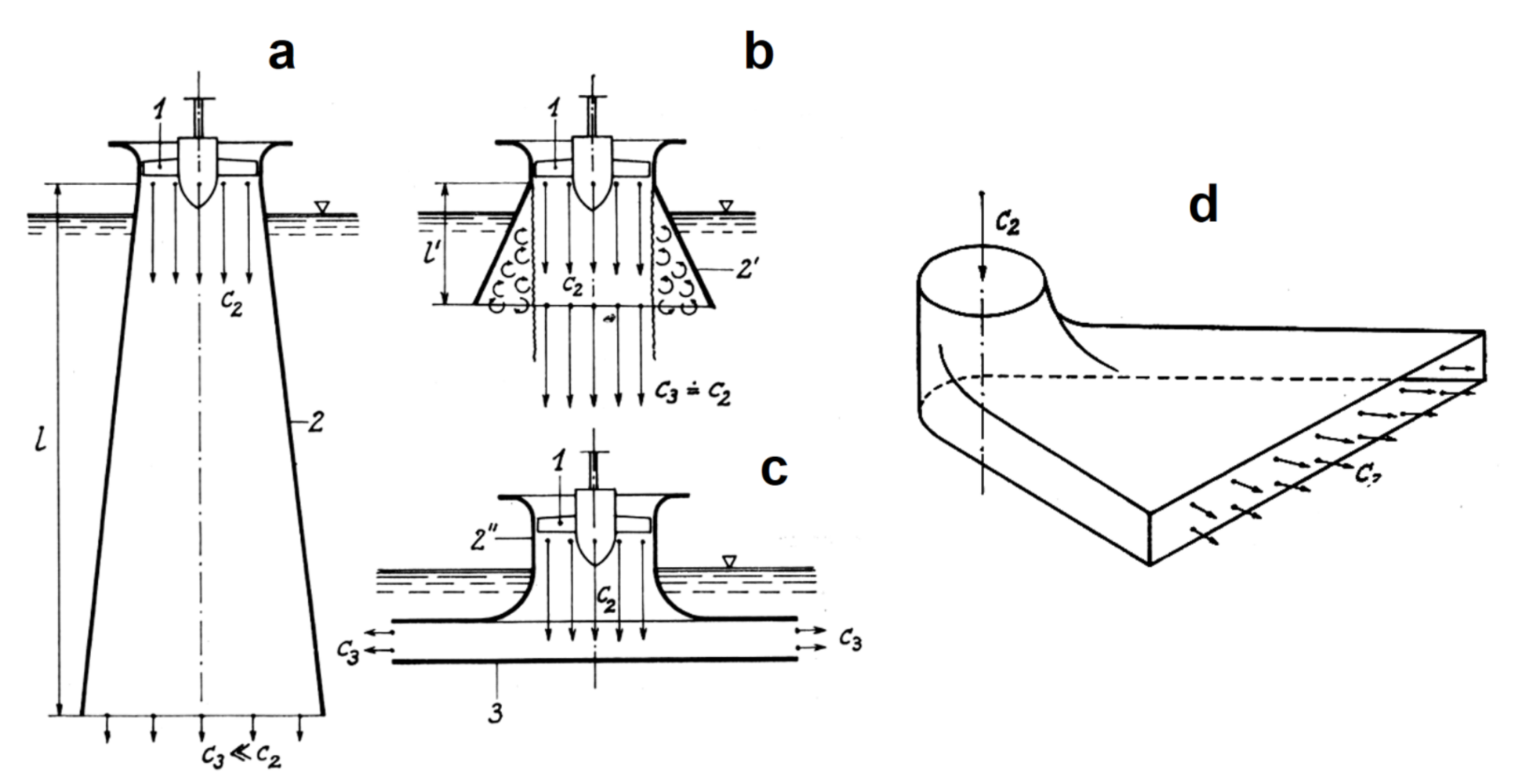
To achieve the highest possible turbine specific speed, the impeller blades should have the highest possible circumferential velocity on the smallest possible impeller radius. However, one problem arises here: if the water flows out of the impeller at this high velocity, the energy not used by the turbine would also go away with it; that is, the loss. This loss can only be reduced by reducing the velocity of the water exiting the impeller. This can be achieved by using a so-called draft tube with a gradually increasing profile where the kinetic energy is converted into pressure energy [
4]. The principle is shown in
Figure 10a.
If the length of the draft tube is sufficient, the velocity (c
2) is reduced to the required value (c
3). However, the required length is usually considerable so its use in practice often meets with economic problems. If we wanted to avoid this by using a steeper widening, the water would be torn off on the tube wall (as shown in
Figure 10b) and that would again mean hydraulic loss. Kaplan took a different path. He directed the water flow from the impeller perpendicularly to a solid wall located under a plate-shaped widening draft tube (see
Figure 10c). It proved to be the way of dealing with the flow with a considerably reduced velocity at a short construction length of the draft tube. From there, the path already led to the creation of a new type of highly efficient elbow draft tube, which is shown in
Figure 10d. The various development variants of the straight draft tubes used in the laboratory experiments are presented in
Figure 11. They are made of glass and were used by Kaplan to study the flow exiting the impeller using a bundle of fibres, as indicated above in
Figure 5.
8. First Installations of Turbines
The first operational Kaplan turbine was delivered to a spinning mill in Velm, Austria, in 1919. It was manufactured by the Storek factory in Brno and had an impeller with a diameter of 600 mm. It worked at an average head of 3 m and a flow rate of 1.1 m
3/s. Warranty measurements conducted by Professor Budau from Vienna proved an efficiency of 86% over a wide load range [
5,
8]. A photograph of the original turbine, which is now on display at the Technisches Museum in Wien, is seen in
Figure 12a.
Figure 12b then shows the same turbine from the historical brochure of the Storek company [
8]. Note the use of the elbow draft tube described in the previous chapter.
The second Kaplan turbine with an impeller diameter of 1800 mm was manufactured in 1920 in cooperation with the Storek and ČKD companies for the power plant in Poděbrady (Czech Republic). It was tested by Professor Hýbl from the Czech Technical University in Prague, who assessed it very favourably [
10]. That ensured a further production of these turbines in Czechoslovakia and then later abroad.
However, in 1922, the first failures emerged, which almost stopped further turbine production around 1924. It was cavitation, a phenomenon unknown to water turbines until then. Several turbines did not show the required output, the blades wore out quickly and the operation of the machine was unstable and noisy. That was a time of great nervous strain for Kaplan, as the licensed companies requested advice and no explanation was to be found in the literature [
3]. Kaplan wrote about this in his book in 1930: “There had been increased reports of an unusual amount of air release and an explosive rumble. Neither I nor the other engineers knew what to do. Then I fell into a serious illness, the traces of which I still feel today” [
5]. Only after another effort to solve cavitation were these last childhood diseases of the Kaplan turbine overcome and the inventor could then fully enjoy his success.
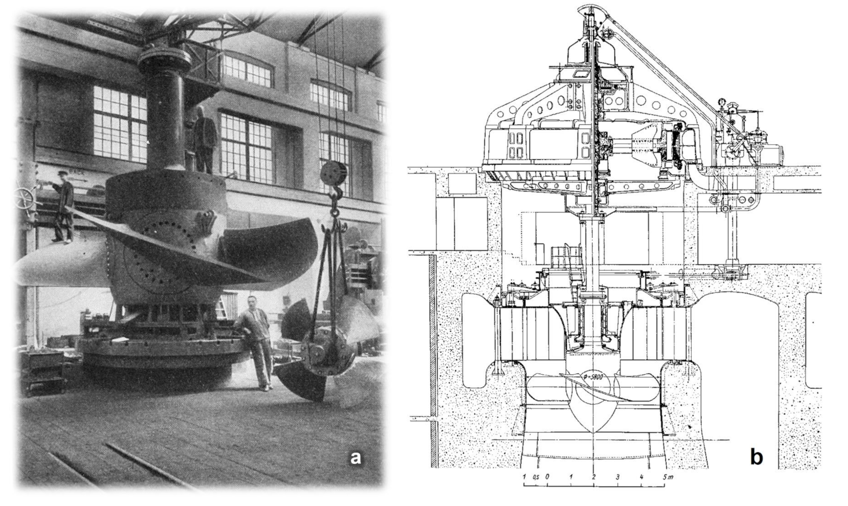
In 1925, the then largest turbine in the world with an output of 8.2 MW and an impeller diameter of 5.8 m was set into operation at the Swedish power plant, Lilla Edet.
Figure 13a shows the impeller of this turbine [
11] and
Figure 13b presents the diagram of the machinery arrangement with a generator [
5].
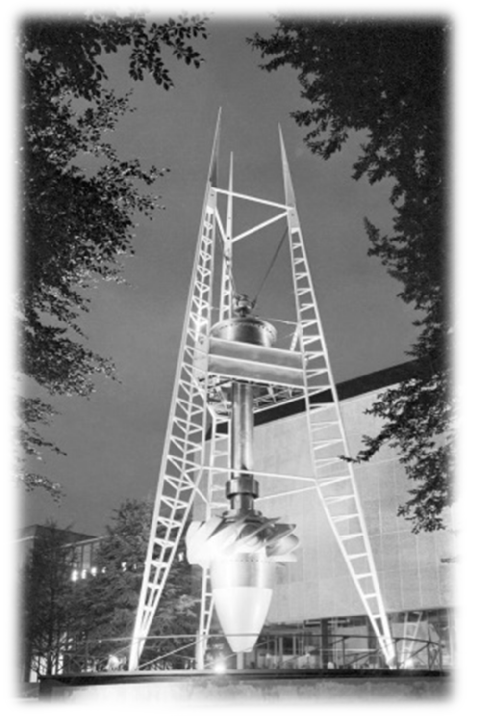
In 1961, a Kaplan turbine for the hydropower plant Orlík in the Czech Republic scored another world first [
12]. The turbine was designed and constructed for a head of 70.5 m (manufactured by ČKD Blansko). Until then, the Kaplan turbine had not been built anywhere in the world for such a high head [
13]. For this reason, its construction required a few special procedures and materials. For this innovative achievement, the turbine was awarded a Gold Medal at the Expo 58 world exhibition. Its impeller was displayed as one of the exhibits in the vicinity of the Czechoslovak pavilion (see
Figure 14) [
14].
9. Conclusions
In 1931, Viktor Kaplan left the German Technical University in Brno and retired to an Austrian homestead in Rochuspoint, Austria. That is also where he died on 23 August 1934.
The significance of Professor Kaplan’s invention consists primarily of the fact that the speed of water turbines more than doubled. The turbine can reach a high speed even in a wide range of changing flow rates and with excellent efficiency. In this way, the potential of economically usable hydropower expands significantly to streams with a low head and variable flow rate. Kaplan’s ideas also influenced the design and development of other machines; first and foremost, these are axial pumps. Blade adjusting is also used for blowers and boat and plane propellers. The solution of the Kaplan turbine also gave an impulse to the development of hydrodynamics. A method of using aircraft profiles for the construction of blades was developed and the theory of blade grids was elaborated. The problem of cavitation is still being studied both in terms of the physical aspects and hydrodynamic conditions.
Finally, a joint photo is presented in
Figure 15. Professor Viktor Kaplan is with his wife, Margaretha, in the foreground in the middle. On the far right, there is Ignaz Storek, the owner of the foundry of the same name and later the first manufacturer of the Kaplan turbines (including the one in the background of the picture). It is probably Jaroslav Slavík at the top of the impeller, a former student of Kaplan and later an assistant; he helped him greatly with the development of the turbine and, during Kaplan’s illness, with the handling of the patent agenda.


