1. Introduction
The mobile wireless networking sector has advanced at a frenetic pace in recent times. The popularity of second-generation (2G) wireless cellular communication has prompted the introduction of broadband third-generation (3G) mobile phones as well as other wireless applications, such as wireless local area networks, Bluetooth, home radio frequency (RF), and local multipoint distributed networks (LMDNs). The antenna is a critical component in any wireless transmission and reception system. Antennas with multifunctional, low-power, and multiband wireless applications are highly preferred for safety and mobility. All of these demands necessitate the creation of highly effective, small-sized, and low-profile antennas that can be integrated into wireless devices. It is anticipated that the commercial deployment of 5G will be approximately in the early 2020s [
1,
2,
3].
One major difference in enabling technology for 4G and 5G communication is using millimeter wave (mmWave) frequencies, aiming for wider bandwidth and better spectral efficiency [
4]. However, moving away from the current mobile service frequencies (<4 GHz), up closer to the mm-wave bands, introduces new features that require cautious consideration [
5,
6,
7]. For wireless applications, Kaushik Mandal and Partha Pritam Sarkar [
8] developed a wideband high-gain antenna in the shape of a U, with modified ground structures. To achieve multiband performance, a U slot patch antenna with an L feed probe was used [
9]. Wei Xing Liu et al. [
10] developed a small open-slot antenna that improves bandwidth while preserving ultra-wideband performance. One strategy for increasing bandwidth and antenna downsizing is to use fractal shapes. Fractal self-similarity and space-filling features are important for obtaining wide bandwidth [
11,
12].
The self-similarity attribute can be thought of as a division of a whole shape into subparts, each of which is a reduced replica of the whole. Antennas exhibit multiband and broadband behavior as a result of this. Because they have a long electrical length but aggregate into a compact physical volume and use space effectively, they have a space-filling property that causes them to shrink in size. The discontinuities caused by the fractal’s complicated and ragged shape boost the antenna’s bandwidth and effective radiation. Mohammad T. Islam et al. [
13] proposed a circular-hexagonal fractal antenna for super wideband applications.
W.J. Lui et al. [
14] presented a frequency-notched ultra-wideband (UWB) fractal-printed slot antenna with a Koch curve slot. A fractal microstrip antenna for current telecommunication systems was presented by A. Azari et al. [
15]. Naresh K. Darimireddy et al. [
16] used the ROGERS RT DUROID 5870 as a substrate to develop a miniaturized hexagonal-triangular fractal antenna for wideband applications. Ground structure is defined as a deficient ground structure with a rectangular open slot in the center. The patch is made out of hexagonal rings and triangular pieces that form a fractal pattern with the antenna. A partial ground plane reduces return loss when compared to a full ground plane. M. Koohestani et al. [
17] presented an ultra-wideband printed monopole antenna with a partial ground plane for UWB communication systems. Wideband features can also be obtained by changing patch and slot geometries, employing stacked patches, and using varied feed architectures. The first work by Mandelbrot et al. [
18] found that fractals have a wide range of uses in various fields of science and architecture. One area is fractal electrodynamics, where fractal geometry satisfies electromagnetic assumptions to explore another category. The best in the most promising field of fractal electrodynamics questioned its application in speculation and receiving cable planning [
19]. Traditional antenna frame research and structural methods are created in Euclidean geometry. Nevertheless, impressive measures have been taken to maintain interest in the possibility of new antenna devices. Fractals have been used in the designs instead of Euclidean geometric ideas [
20].
From this rapidly evolving new research field has come the creation of fractal antenna cables. Since fractal geometry is an extension of established geometry, its constant representation provides a rare opportunity for construction to explore an infinite number of configurations that could not be achieved before, which are now used to encourage creative new antenna projects. There are mainly two dynamic research fields in the construction of fractal antenna devices [
21]. These include the study of components of antenna devices formed by fractals and the use of fractals in the design of antenna device groups. The motivation behind this article is to outline the current progress in the assumptions and design of the components of fractal antenna devices represented by fractal antennas.
This article also discusses the relevant areas of specific fractal repeating surfaces [
22] as a technique to minimize antenna dimensions while retaining excessive radiation efficiency; fractal antennas have drawn unique interest in microwave engineering. A fractal is essentially a rough or shattered geometric shape that may be dissected into sections, each of which is a smaller version of the total. Antenna theory employs cutting-edge (fractal) geometry [
23], a natural extension of Euclidian geometry. Various types of novel antennas have been studied and widely published in the last two decades. Among those, microstrip fractal blooms are being developed for modern wireless communications for better radiation characteristics [
24].
The remainder of this paper is organized as follows:
Section 2 presents the related works,
Section 3 presents the proposed fractal antenna array geometry,
Section 4 presents the results, and
Section 5 outlines the conclusion.
2. Related Works
In today’s wireless communication systems, a radiating element with superior characteristics and limited volume and cost considerations is important. Antenna researchers have previously developed a range of methods to increase the compact patch antenna’s gain and impedance bandwidth [
25]. Some researchers [
26] have provided a thorough examination of reflector antennas, including their precise methods, feed system theory, architecture, and analysis, as well as tracking and controlling methods. A small ultra-wideband microstrip line feeding a circular-shaped ring patch antenna with a defected ground surface was proposed for wireless networking applications [
27]. The engraved partial slot in the shape of a circular ring causes frequency notching. Antenna miniaturization is based on fractal methodology characteristics such as self-similarity and gap-filling results in increasing electrical length, which are useful in achieving broadband capabilities [
28]. Novel fractal geometry has been linked to antenna radiating elements using Koch spline curves for multiple resonant frequencies [
29]. Werner and Ganguly [
30] presented a systematic overview of techniques for designing fractal antennas.
Several investigations [
31] have described novel fractal designs that ensure the assortment of geometry for reducing compact magnitudes, increasing antenna dimensions, and retaining the same radiating characteristics across the broadband. Microstrip antennas with different shapes of slots and slits are equipped for wideband applications. Circular polarization with high gain S-band communication with 4 asymmetrical V-shaped slots at the corners of the rectangular microstrip patch antenna has been developed [
32]. The occurrence of defective ground surface (DGS) causes current distribution at the antenna’s ground plane to be disrupted, changing the DGS region’s corresponding circuit parameters. The use of split-ring resonators as an LC parallel resonator in compact patch antennas results in a lower resonating frequency [
33].
A defective-ground-surface-based rectangular patch antenna [
34] has been used to demonstrate the high polarization purity in radiation fields while improving impedance bandwidth. For multiband applications, a rectangular microstrip patch with a dumbbell-shaped DGS has been developed in a compact zigzag form slit and slits of double T-shaped on either side [
35]. For wideband applications, parametric studies have been proposed for a novel octagonal fractal antenna [
36], an ultra-wideband (UWB) compact planar antenna fed with a rectangular slot coplanar waveguide [
37]. The asymmetrical positioning of the substrate with a defected ground plane with a rectangular slot type of fractal antenna has been proposed. To achieve broad impedance bandwidth, Sarkar et al. [
38] proposed a DGS-based U-shaped patch antenna. For wireless broadband applications, lightweight, low-profile, low-cost, and wide-bandwidth antennas are needed to meet evolving market demands. Over the range of 3–25.2 GHz frequency, the projected fractal antenna has an 8.4:1 wide-bandwidth ratio, with gains fluctuating from 3 to 9.85 dBi.
The antenna’s high gain and wide impedance bandwidth make it ideal for a variety of wideband communication applications. The proposed antenna geometry is very flexible in terms of polarization, bandwidth, radiation pattern, and gain [
39]. The proposed fractal geometry provides substantial bandwidth enhancement that can be observed by proper feed and slot-loading technique selection as well as miniaturization with higher iterations. The design and development of antennas for implementation in multiband systems are one of the crucial challenges. Multiband antennas must work over the 7.5 GHz impedance bandwidth with a return loss below 10 dB (S11 < −10 dB), with an omnidirectional indoor radiation pattern. Multiband networking is suitable for indoor wireless communication with a short range [
40]. Multiband signals can penetrate through various materials effectively. Multiband signals are, however, useful when they occupy a low-frequency portion of the radio spectrum [
41]. The material penetration capacity of these signals is important. The configuration of the building and the construction materials used affect radio wave propagation in the indoor case. The coverage degree is well defined by the building’s geometry, as shown in
Figure 1.
Despite the miniaturization capabilities of the approaches outlined, they usually result in a compromise in dimensions, bandwidth, and radiating efficiency. To address this problem, a combination of several miniaturization approaches can be used to mitigate the disadvantages. Varamini et al. produced a small microstrip antenna with dual-band features by combining metamaterial and fractal approaches, in which a slot antenna is developed using Minkowski fractals and Sierpinski carpet, and then a metamaterial unit cell is loaded on the antenna’s slot region. At 3.2 and 4.5 GHz, the proposed antenna displayed two resonance frequencies [
42].
This work describes an effective way for combining miniaturization techniques to create a multi-resonance antenna with small size, high gain, and efficiency. A new method for designing a multi-resonant hexagonal antenna array is devised and demonstrated. Furthermore, to achieve greater miniaturization and a triple frequency band of operation, the proposed antenna array is carved on the radiating patch of a microstrip antenna. This research is completed in four steps [
43]. The design technique and simulation results of the new modified hexagonal array are presented in the first step. To achieve multi-resonance and to minimize the size, the second stage engraves modified microstrip feeding. The hexagonal fractal is next added around the patch’s borders to increase impedance matching, which is referred to as Stage 3. Finally, a hexagonal slit is etched from the ground plan center to improve radiation characteristics while reducing return loss.
Fractal Materials and Methodology
One can envision objects with zero dimensions, such as 0D (points), 1D (lines), 2D (plane), and 3D (space) (solid). By integrating the 2D images from each of our eyes, we build a 3D view of our surroundings. Multidimensional objects, such as 4D, 5D, and 6D, can also be imagined. Traditional geometry and calculus approaches are ineffective for understanding fractals, necessitating the use of other methods. It is largely a deeper analysis of patterns of life that gives original reasons for growth in fractal geometry. The similarity dimension (DS), the division dimension (DD), the Hausdorff dimension (DH), the boxing counting dimension (DB), the correlation dimension (DC), the information dimension (DI), the point-wise dimension (DP), the averaged point-wise dimension (DA), and the Lyapunov dimension (DL) are among the many definitions of fractal dimensions [
44], many of which are evaluated in [
45].
The last seven dimensions are extremely useful in identifying fractal structures in the form of strange attractors, which are related to chaotic dynamics. Among the many definitions of fractal dimensions [
46] are the similarity dimension (DS), the division dimension (DD), the Hausdorff dimension (DH), the boxing counting dimension (DB), the correlation dimension (DC), the information dimension (DI), the point-wise dimension (DP), the averaged point-wise dimension (DA), and the Lyapunov dimension (DL). As a result, the primary tool for describing fractal geometry is a dimension that can take many different shapes. The dimension determines the space to be filled in a significant simplification. When we examine it at a very small scale, this is a measure of how many abnormalities are exposed. The dimension offers a lot of information about the fractal structure’s geometric features [
47].
Normal complex structures include galaxies, cloud borders, snowflakes, trees, leaves, ferns, mountains, and coastlines [
48]. Nature has strengthened the architecture of the evolution of biological mechanisms to transmit and use resources efficiently, and, ultimately, in any critical structure, a fractal shape can be found. It is very often difficult for Mandelbrot [
49] to describe existence only in terms of Euclidean geometry—straight lines, circles, squares. He suggested the definition using real fractals and fractal geometry objects, including arbores, flashes, meanders, rivers, and coastlines, to mention just a handful. The non-integrations can be fractal dimension; thus, it can present as an intuitive calculation of how much space is filled by the fractal. Fractals can be possibly found or created from a mathematical recipe in nature. Face Benoit Mandelbrot’s term ‘fractal,’ often coined as the father of fractal geometry, which was referred to as “I”, is a Latin adjective fractus coined fractal. Face Frangere means to “break” to produce the corresponding Latin verb fragments that are irregular. Hence, it is sensitive—and how? It is suitable for our need! The “fragmented”, besides fractus, can also mean fractus (as in fraction or refraction) “irregular”, where the two meanings of a fragment are retained [
50]. He also asked, “Why is geometry frequently defined as cold or dry? One explanation is that it cannot identify a cloud, a mountain, a coast, or a tree form. Nuclear is not circles, not cones of mountains, not shorelines; the circles are not flat, and is not moving or in a straight line, traveling by light”.
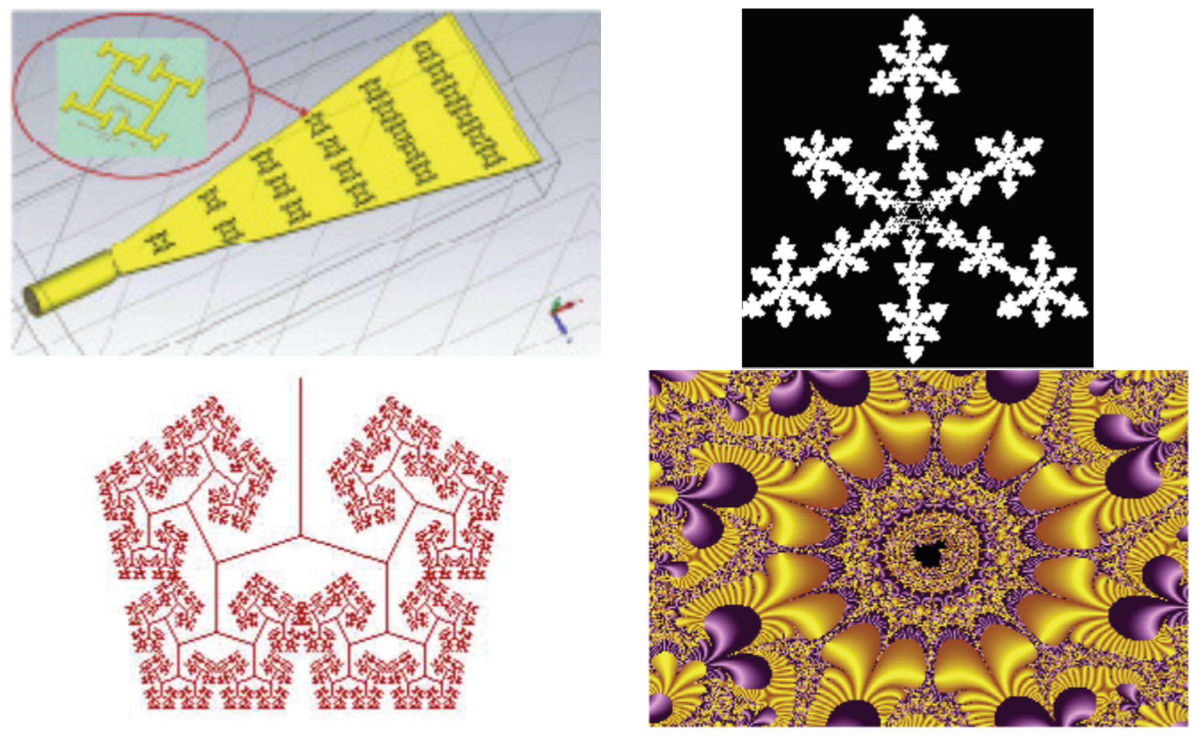
Figure 2 shows various fractal structures [
20].
3. Design Methodology
The proposed antenna construction in this paper is built using the monopole hexagon form. However, with a monopole arrangement, the impedance bandwidth is limited. As a result, a hexagonal microstrip fractal antenna of the same form but different dimensions was developed to improve the radiation characteristics, impedance bandwidth, and the monopole hexagon (HMSFA). For its UWB features, the suggested radiating patch structure employs numerous hexagons to create fractal geometry. The hexagon antenna receives microwave power via the CPW (coplanar waveguide feed) [
2,
4,
7]. The modified microstrip feed has a two-step construction to match the antenna’s input impedance and the power-fed connector’s output impedance to 50 ohms. The current density is lowest in the center of the monopole patch and highest towards the margins. As a result, the cut in the center (middle) of the monopole hexagon is the largest of all the other dimensions employed in the patch for fractal geometry development. This will help disperse the current evenly throughout the patch and along its edges, resulting in good radiation properties. Using the Ansys HFSS software tools, the proposed hexagonal microstrip fractal antenna array (HMSFA) structure was simulated. The antenna’s extensive parametric analysis was confirmed, and the optimum impedance bandwidth was observed and measured in millimeters in antenna laboratories. The antenna’s testing results are measured using an R & S vector network analyzer, model ZVA40.
3.1. Iterated Function Systems (IFSs)
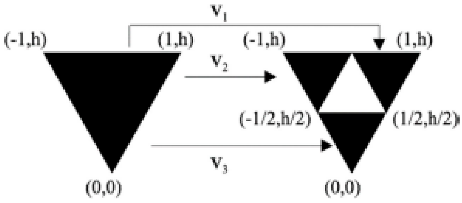
The geometry of the proposed hexagonal antenna array consists of eight small hexagonal shapes that are built through compressing and grouping one-third of their initial iterations in this hexagonal generator. The antenna was configured using a 1:3 miniaturization ratio. The iterated function system (IFS) is the name for this miniaturization method, which is defined by the matrix equation [
32].
or equivalently by
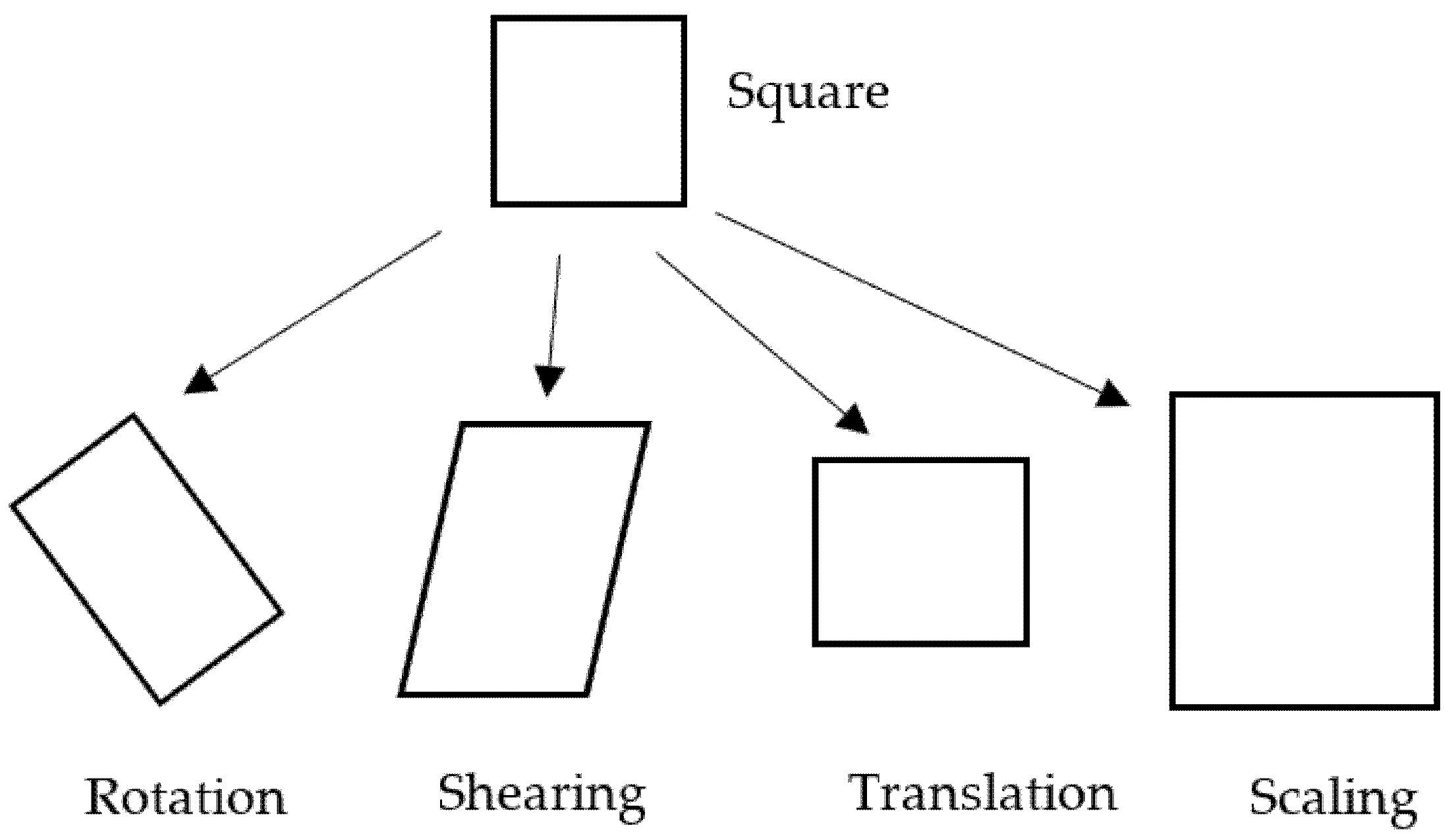
where real number coefficients (w, x, y, z, a, b) are controllers of the motion of the fractal object in space: w, z—scaling, x, y—revolution by
,
with reference to the coordinating axis, and the vectors a and b—the vectors lend to linear translation, respectively, (see
Figure 3) and are expressed mathematically as:
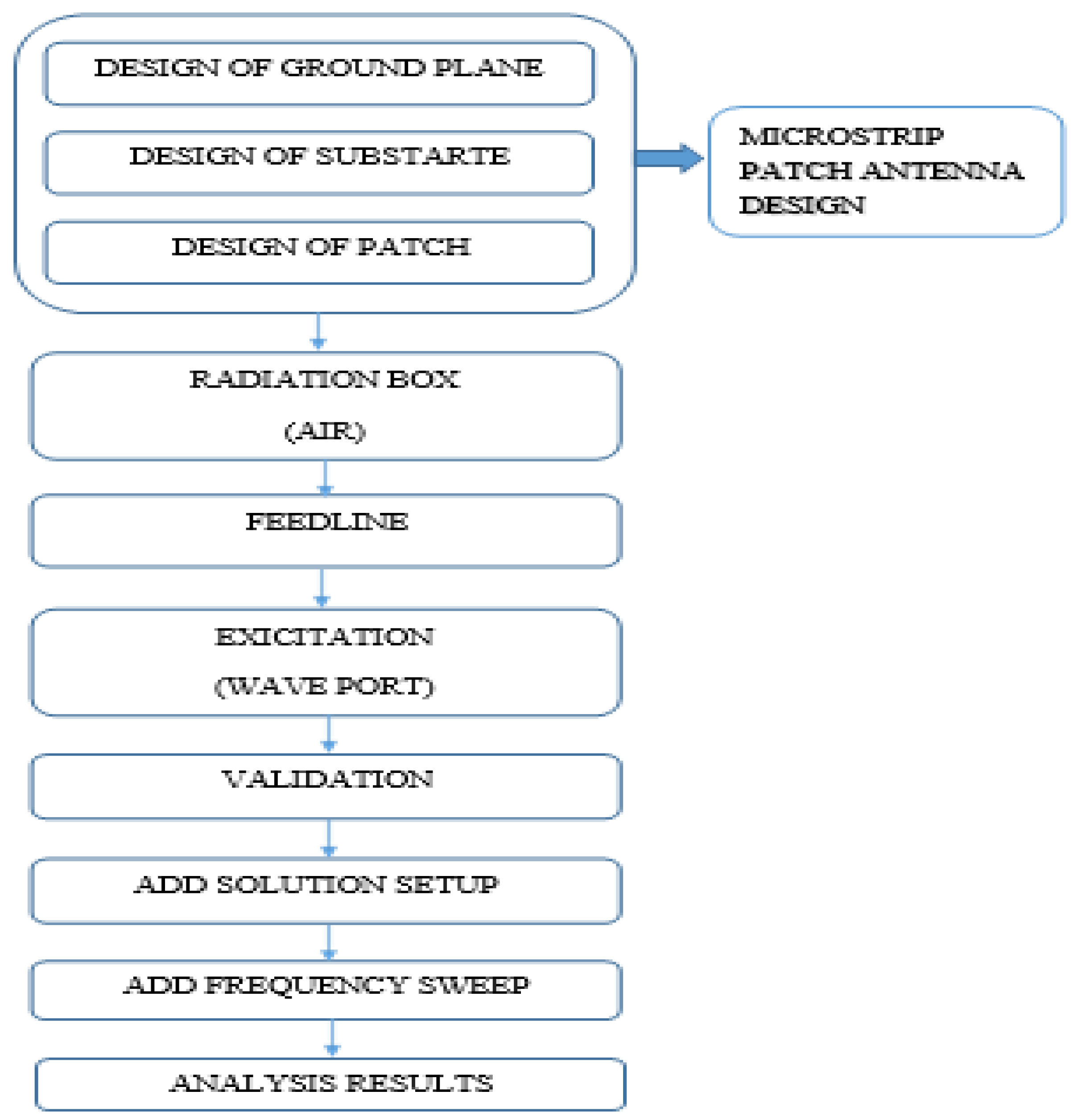
The proposed geometry of the antenna system is better at maintaining the total conductivity and radiating characteristics of the antenna. The antenna is 59 mm in total width and length of 29 mm, while the height of the substrate is 1.6 mm, loss tangent, tan δ = 0.019, and dielectric constant εr = 4.4. For the second iteration, the hexagonal fractal antenna had made a further small hexagonal slot at its center. Furthermore, the miniaturization produced eight smaller hexagons around a large hexagon in the third iteration. The excitation is through the coaxial, with the diameter of the probe being 3.0 mm at the center resonating frequency of 2.5 GHz. The smaller compact hexagons within the patch increase the surface radial current distribution and, hence, the overall conductivity of the patch, resulting in stronger radiation. The following flow diagram (
Figure 4) symbolizes the workflow in designing conventional patch antennas in HFSS.
3.2. Fractal Antenna Design
The iterative function system (IFS) used to describe the generator is shown in Relation 4:
where n is the iteration number and θ is the angle toward the middle.
The proposed antenna is 25 mm × 30 mm in size and 0.8 mm in substrate thickness. The radiating element is 18.32 × 19.4 mm in dimension.
Ymn = Y11 (for mode TM11) = 1.8412,
Y21 (for mode TM21) = 3.0542,
Rc = effective radius of CPA,
c is the speed of light in freespace,
ε
reff = effective dielectric constant.
where R
c is the radius of CPA, and t
S is the thickness of the substrate. The circular patch radius is given by
The parameter, Z =.
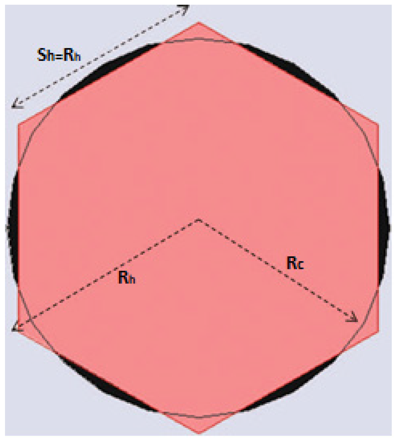
The thickness of the substrate is denoted by the letter t. By linking the areas of the circular patch antenna (CPA) with a hexagonal patch antenna (HPA), as shown in
Figure 5, the f
res is used for building a hexagonal antenna.
where S
h is the slanting length of each side of the hexagonal patch antenna (HPA).
3.3. Equivalent Circuit Model of Proposed Hexagonal Fractal Antenna Array
The proposed fractal antenna exhibits the characteristic of a bandpass filter on observing the S11 parameter. By normalizing the basic circuit elements, the antenna equivalent lumped element network model is developed. Resistance (R), capacitance (C), inductance (L), and conductance (C) can be used to describe an equivalent lumped circuit of a microstrip antenna. The proposed antenna’s conducting portion is loomed as a combination of R and L elements in series, as shown in Equations (10) and (11), respectively [
51].
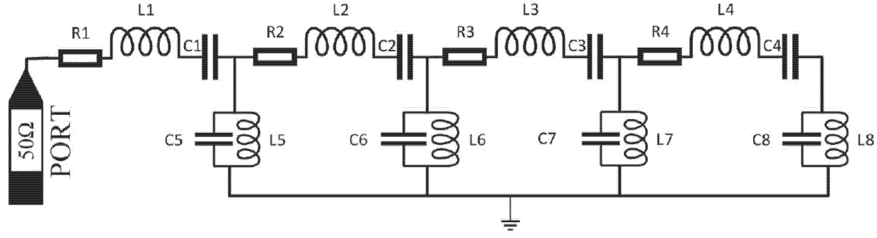
The radiating patch and feedline in the top layer and defected ground plane in the bottom layer of the proposed fractal antenna are detached by FR-4 epoxy dielectric substrates, resulting in a C and G parallel combination. Equation (13) calculates the value of C. A high pass filter is developed by combining R, L, and C resonance circuits in order, while a low pass filter is created by combining L and C resonance circuits in parallel. As shown in
Figure 6, this lumped element circuit model has 4 resonating modes of R, L, and C elements in series and parallel L and C components. The proposed antenna’s scattering parameter was determined using the HFSS simulator [
36,
37,
38,
39], and each resonating circuit was tuned at a particular frequency to match it. The equivalent circuit’s optimized resistances, inductors, and capacitors were modeled using the following equations.
where copper conductivity, skin depth, angular frequency, surface inductance, surface resistance, capacitor, substrate height, effective permittivity, effective width, and effective magnetic permeability are denoted by t, σcond,
, ω, L, R, C, h, ε
reff, W
eff, and μ
0, respectively.
Table 1 shows the values of the lumped elements of the equivalent circuit parameters (shown in
Figure 6).
In general,
and
where n = 5, 6, 7, 8 and
i = 1, 2, 3, 4. The input impedance (Z
in) is calculated as
The reflection coefficient (
), VSWR, and return loss can be expressed as
where
Z0 is the characteristic impedance of the feedline.
3.4. Parametric Analysis
The optimization of antenna parameters is performed by parametric analysis. It aids in examining the impact of various parameters on bandwidth and impedance. Genetic Algorithm (GA) and Particle Swarm Optimization (PSO) algorithms can be used to evaluate an antenna structure that meets a set of user-defined dimensions and impedance-matching performance constraints. In this analysis, a genetic algorithm is used for optimization.
3.5. Field Distribution and Surface Current Analysis
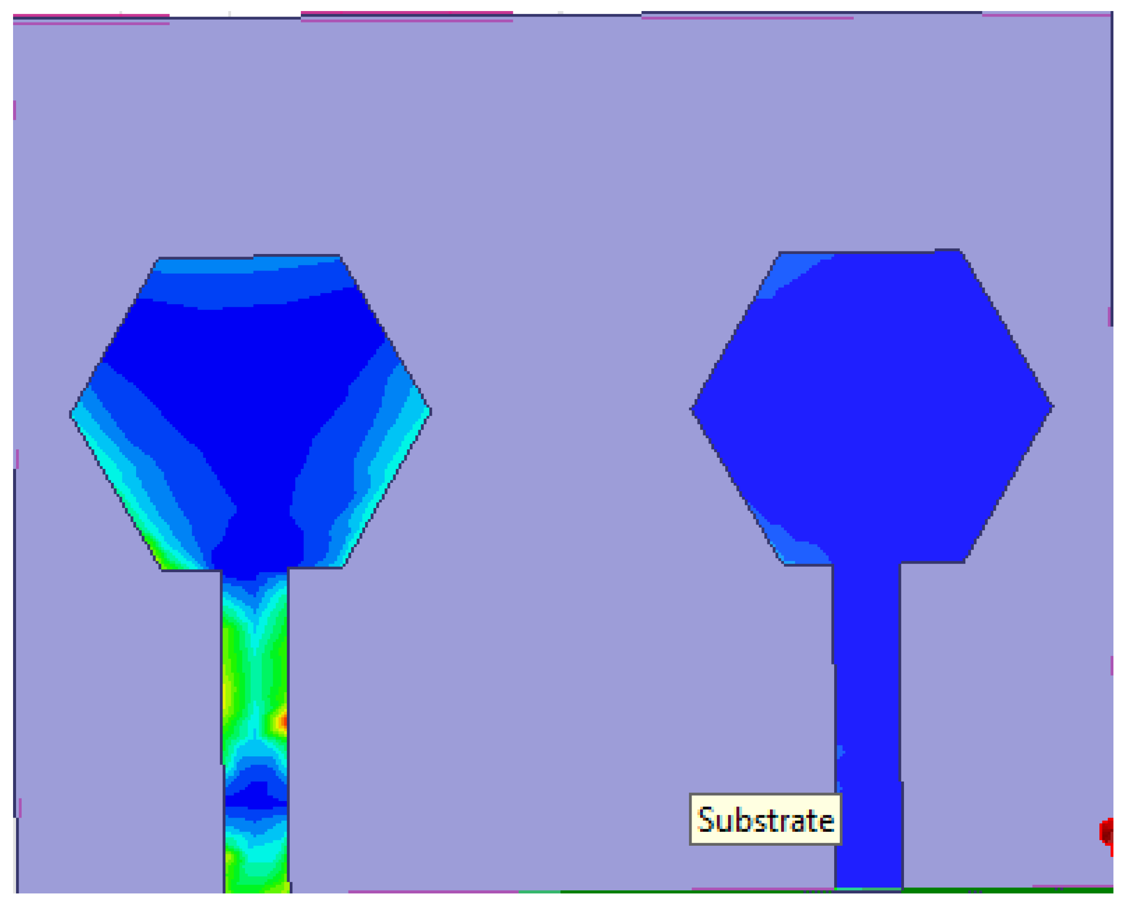
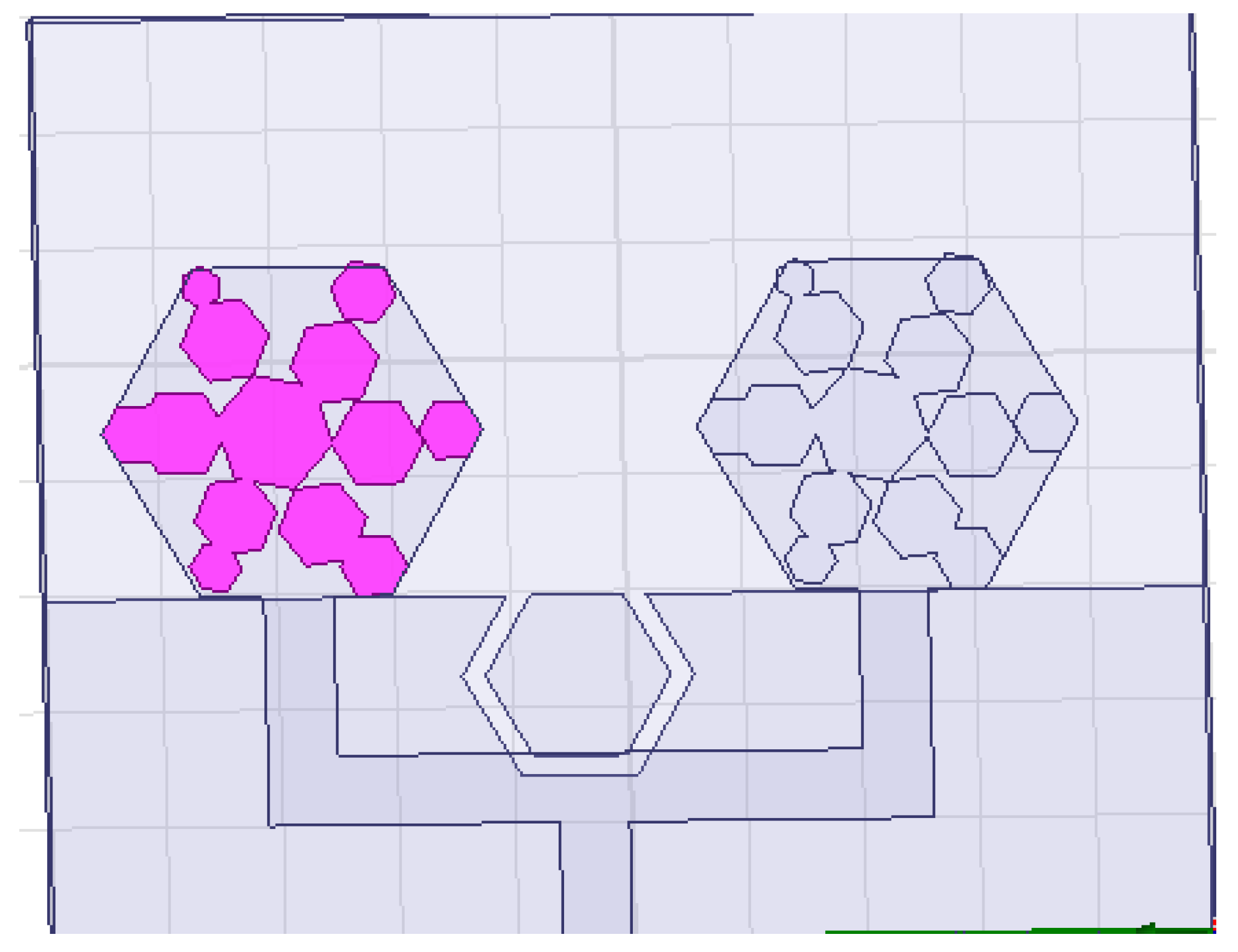
Figure 7 shows the surface radial current distribution analysis for all iterations at 2.48 GHz. The wideband characteristics are caused by the surface currents laterally over the hexagonal outer rings with triangular element boundaries, which gains additional resonances and results in increased gains by maximizing electrical length through fractal iterations. The fractal design of the antenna and its broadband output is compromised by the concentration of current distribution along the edges of the fractal hexagonal outer rings.
From the surface current distributions for various resonating frequencies of the proposed antenna, it is noted that the current density is higher in the system closest to the edges than in the interior portion of the antenna in all cases. The mutual inductance and capacitance of the proposed hexagonal antenna are influenced by the current density near the edges. Because of the accumulation of charges at the triangular edges and over the boundaries of the inner and outer hexagons, the fractal’s electrical length validates the antenna’s broadband output. The surface current distributions focus mainly on the patch and feed line’s lower half.
The proposed hexagonal fractal antenna is realized in a microstrip-fed structure with overlapping apexes to maintain electrical self-similarity. The hexagonal fractal appears to have identical scaling dimensions of one-third when viewing from the input of the corner, indicating that it can produce resonators. The hexagonal ring fractal also appears to have identical scale lengths of one-third of the corner input, indicating that it can yield resonant frequencies in multiples of three [
51]. As needed in microstrip patch antenna design, a 44.6 × 79.9 mm ground plane is implanted on the rear side of the substrate. Larger dimensions of the ground plane yield better radiation efficiency in general, but there is a constraint to the maximum size of antenna that can be used.
4. Results and Discussions
The radiation characteristics of the proposed hexagonal fractal antenna, including the S
11 parameter, gain, radiation pattern, performance, and VSWR of the proposed antenna, are all discussed here. To increase the number of iterations in the parametric tests, as shown in
Figure 8, it is observed that as the number of iterations increases, so does the impedance bandwidth as well as the complexity of the radiating patch. Parametric analysis is used to determine the effect of feedline width (w
f), ground plane length (l
g), substrate width (W), and substrate length (L) on the other parameters. The S
11 characteristics of the proposed antenna obtained through simulation, measurement, and analogous circuit model analysis are very similar. It can be shown that it operates efficiently at frequencies ranging from 2.2 to 10.5 GHz, with a 146% bandwidth. In the entire frequency band (2.2–10.5 GHz), the voltage standing wave ratio (VSWR) is lesser than 2, indicating strong impedance matching characteristics. The amount of return loss, dB, and bandwidth generated by each iteration will vary.
4.1. Comparing Performance Parameters
A comparison of the performance of hexagonal fractal antenna array (HFAA) antennas of different iterations with the other conventional GPS navigation antennas is shown in
Table 2. One of the advantages of this design is that the radiation pattern in the antenna with a strip is of the broadside type throughout the entire matching bandwidth.
Table 2 summarizes the measured gain, axial ratio (AR) bandwidth, and impedance bandwidth of the conventional fractal antenna, with and without defective ground structure, at the mentioned frequencies. The expected improvement in radiation characteristics may be observed clearly, particularly around 3.6 GHz. For correct impedance matching of the fed system with antenna impedance, the CPW-Fed is a one-step system with fed width (f) = 1.6 mm and feed length (t) = 6.54 mm. A step-fed step [
5] is one of the design parameters that helped in increasing the overall radiation characteristics of fractal antennas from 3.1 to 10.6 GHz. The increased return loss characteristics in the frequency region with the feed structure are below −10 dB.
4.2. Return Loss
The fractal antenna in the proposed design radiates along the periphery of triangular and quadrilateral edges and also along the triangular radiating patch, which increases the bandwidth by adding all the multiple resonating frequencies together.
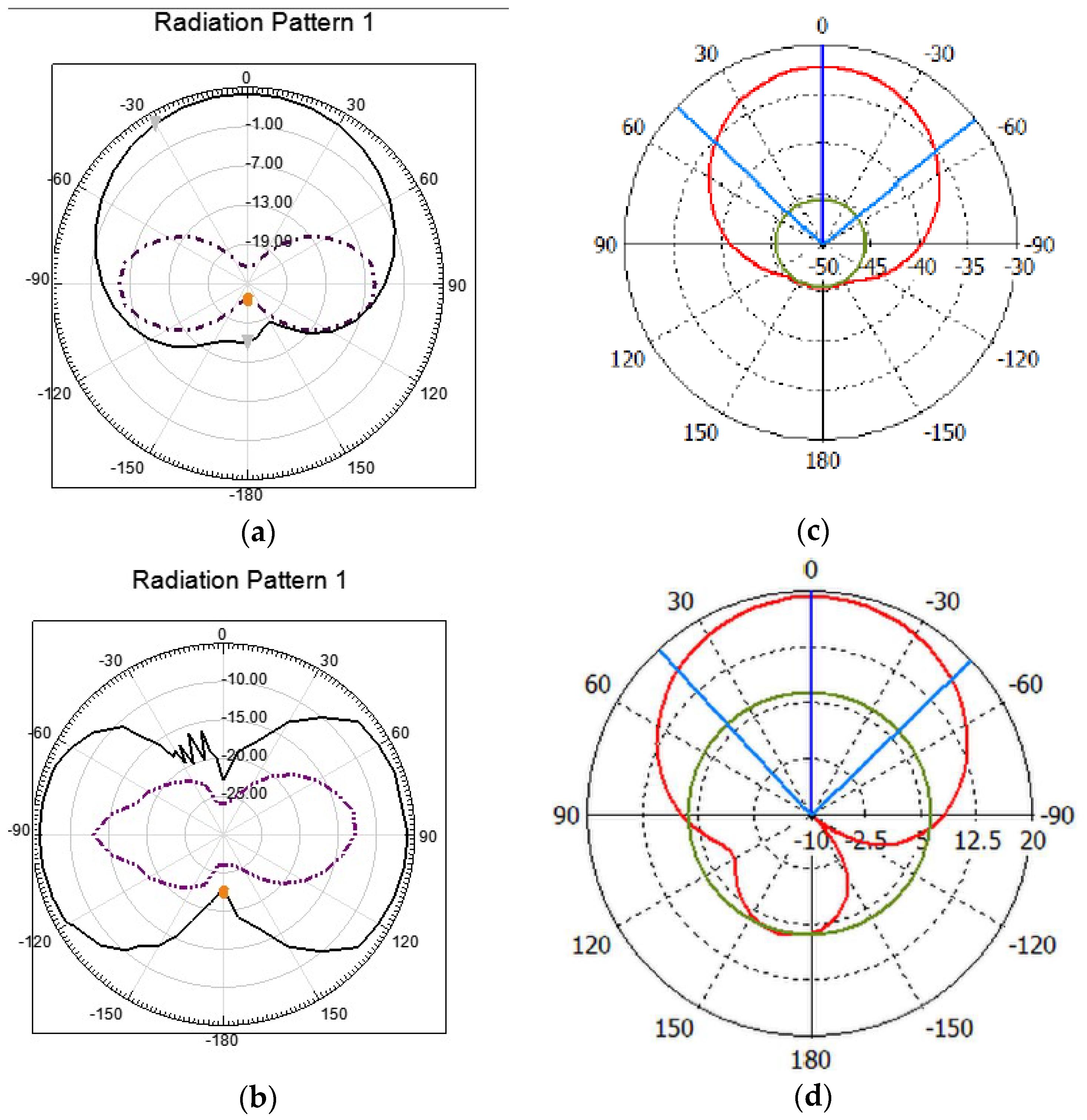
Figure 9 shows the fractal-shaped antenna’s simulated and calculated radiation pattern (E-plane and H-plane) at 3.6 and 5.8 GHz. The pattern shows the H-plane and E-plane shaped like a dumbbell. The pattern is identical to the dipole/monopole antenna’s radiation pattern.
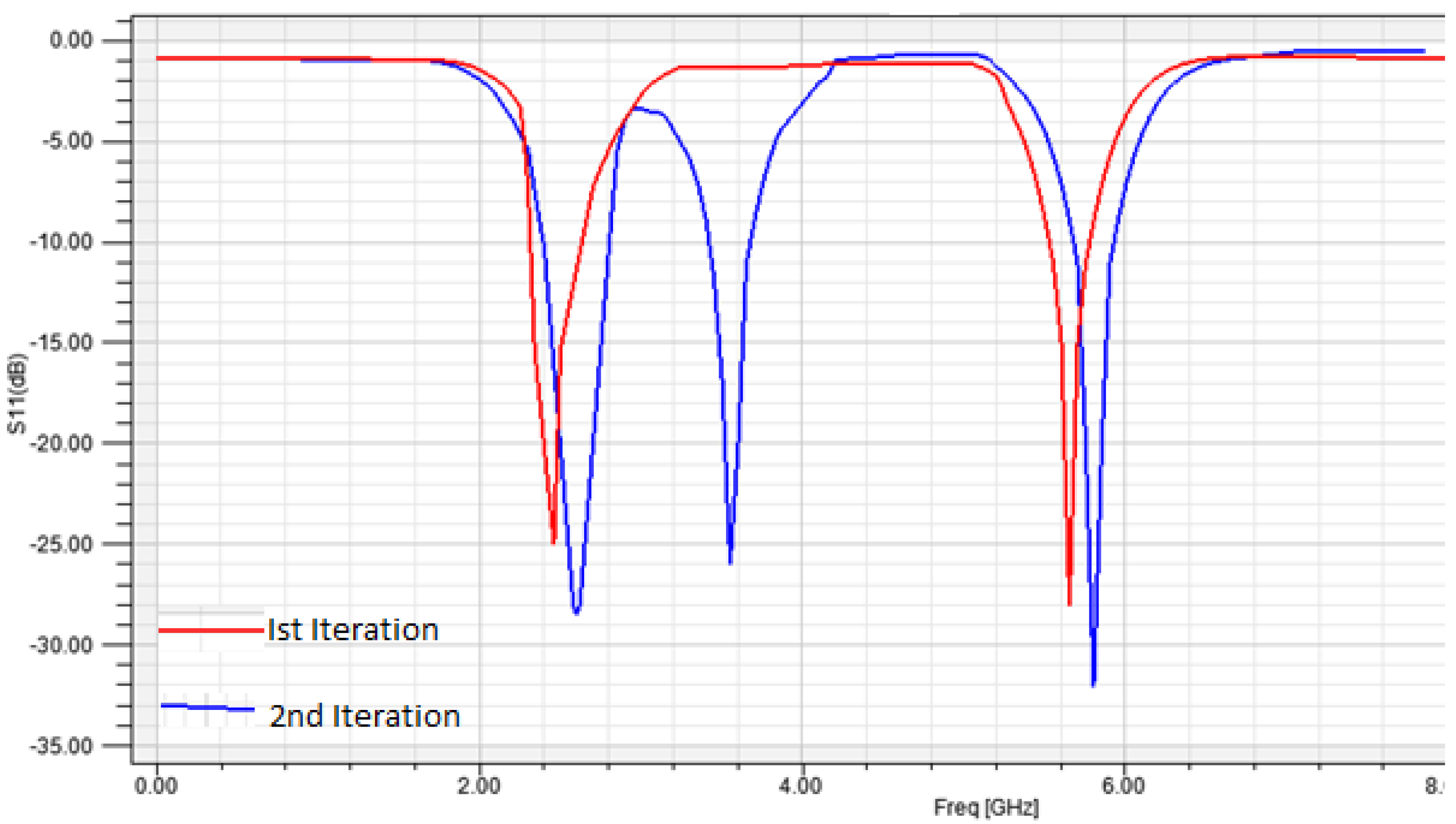
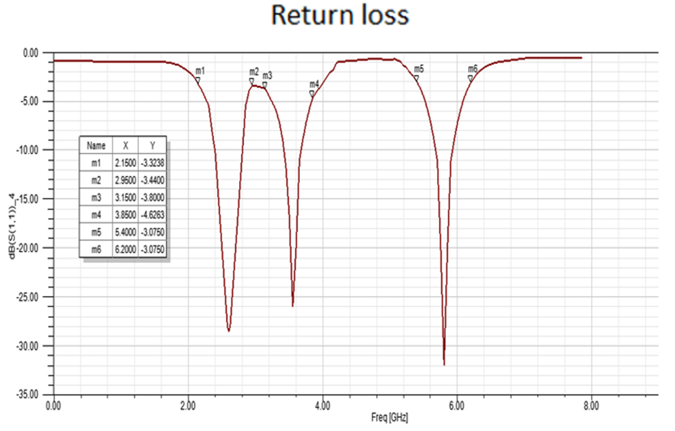
Figure 10 shows the return loss for the hexagonal fractal antenna’s first and second iterations showing −25 and −28 dB for 2.4 and 5.3 GHz, respectively, for the first iteration and −29 dB at 2.48 GHz, −26 dB at 3.6 GHz, and −32 dB at 5.8 GHz during the second iteration. In comparison to the Sierpinski Carpet fractal antenna, the hexagonal fractal microstrip patch antenna possesses a high return loss.
The resonant frequency for the second iteration of the proposed hexagonal fractal antenna array is described in
Table 2. Apart from the initial resonant frequency, the hexagonal fractal antenna generates resonating frequencies that repeat by about a factor of 3. At the second iteration, proper return loss was observed, and the proposed hexagonal fractal antenna’s resonance frequency was determined using the following equation.
where C is the velocity of light, δ is the scale factor, l is the hexagon side length, k is the fractal iteration, and n is the resonance. As the above equation considers a resonance frequency of 2.50 GHz, due to various practical considerations, therefore a center frequency of 2.5 GHz has been considered for analysis. It has been discovered that better impedance matching can be achieved at 2.58 GHz, which is the frequency used for the second iteration. As shown in
Table 3, VSWR is very high and exceeds the limit in the first iteration. The radiating patch at the first iteration works as a hexagonal radiating patch of a fractal antenna, and the VSWR is unreliable due to insufficient conductivity maintenance in the antenna. The simulations revealed that the radiation pattern for the first and second iterations is erroneous due to excessive back radiation. Since there is a single hexagon at the center of the second version, sufficient conductivity is not achieved, thus resulting in insufficient impedance matching and spurious radiation.
4.3. Radiation Pattern
Figure 10 compares the measured H-plane (xz-plane) and E-plane (yz-plane) radiation patterns of the antenna with and without a defective ground structure at 2.48, 3.6, and 5.8 GHz. Across the operational frequency range, the H-plane patterns are symmetrical and patch-like. The E-plane patterns, on the other hand, are not as symmetrical as the H-plane designs.
Figure 11 shows the generated and measured radiation patterns in two major planes, E and H planes, for the three operation frequencies (2.48, 3.6, and 5.8 GHz). The radiation pattern is essentially continuous and directed in the azimuth and elevation planes for low frequencies of 2.48, 3.6, and 5.8 GHz.
Using the NVIS 72 prototype machine, the proposed antenna was built on a low-cost FR4 substrate (semi-automated prototype machine). It was put to the test and measured to ensure that the simulation’s results, such as the reflection coefficient, gain, and radiation pattern, were accurate. The fabricated prototype’s reflection coefficient (the S11 parameter) was measured with a Rohde & Schwarz VNA. As demonstrated in
Figure 11, there was good agreement between the simulated and measured results in terms of the reflection coefficient and bandwidth for this antenna. The simulated reflection coefficient of the same antenna was obtained as −29 dB at 2.48 GHz, −26 dB at 3.6 GHz, and −32 dB at 5.8 GHz during second iterations. For a resonance frequency of 2.48 GHz, the measured reflection coefficient of the antenna was in the range of –29 and −26 dB at 3.6 GHz and −32 dB at 5.8 GHz.
The simulated and measured outcomes are in good agreement, which verifies the designed concept, as shown in
Figure 11. When the suggested hexagonal fractal antenna array is compared to various other conventional antennas for the next generation of wireless technology (5G), it shows that the radiating parameters, such as the reflection coefficient, gain, and radiation pattern, are vastly improved. The suggested rectangular antenna has a smaller dimension and a substantially larger bandwidth than existing reference works, as shown by the simulated and observed findings.
5. Conclusions
A MIMO hexagonal fractal antenna array (HFAA) has been designed, simulated, and fabricated for next-generation mobile handsets. With this structure, there has been some improvement in return loss and radiation characteristics at lower and higher frequencies. By implementing defected ground structure (DGS), the radiating patch achieves better impedance matching. The simulated radiation characteristics, comprising of return loss, is −25 dB at 2.52 GHz, with a 1.58% return loss bandwidth at the first iteration, where the radiation pattern is directive. The transceiver’s simulated return loss was found to be −29 dB at 2.6 GHz and −26 dB at 3.5 GHz, with a 620 MHz bandwidth of −10 dB (1.26%). For the return that has been experimentally confirmed with a return loss of −32 dB at 5.7 GHz, the loss is very promising at 340 MHz bandwidth (1.52%). The findings showed that there was a trade-off between antenna impedance and thickness with bandwidth. In this work, the dimensions of a microstrip patch antenna were reduced using a hexagonal fractal slot at the ground plane (DGS); gains have been improved substantially by about 4.2 dBi at 2.6 GHz, 3.8 dBi at 3.5 GHz, and 3.6 dBi at 5.7 GHz. It is concluded that in the vertical polarization pattern, the horizontal polarization pattern has the fewest nulls at lower frequencies and more nulls at higher frequencies. Wideband features increase surface current distribution compared to traditional antennas. With the addition of DGS, the size of the second iterated antenna was decreased by 43.67%; additionally, DGS also results in the suppression of higher harmonics. However, DGS reduces an antenna’s gain slightly without affecting its efficiency. The difference in gain can be further enhanced by reducing the thickness of the substrate and varying fractal structures. The proposed antenna is appropriate for 5G smartphone antenna systems as it possesses better radiation characteristics compared to existing conventional antennas.


 ,
, 


