Article

Structural Power Performance Targets for Future Electric Aircraft

by
Elitza Karadotcheva
1,
Sang N. Nguyen
1,*,
Emile S. Greenhalgh
1,
Milo S. P. Shaffer
2,3,
Anthony R. J. Kucernak
2 and
Peter Linde
4,5
1
Department of Aeronautics, Imperial College London, South Kensington, London SW7 2AZ, UK
2
Department of Chemistry, White City Campus, Imperial College London, 82 Wood Lane, London W12 0BZ, UK
3
Department of Materials, Imperial College London, South Kensington, London SW7 2AZ, UK
4
German Aerospace Center (DLR), Königswinterer Straße 522-524, Oberkassel, D-53227 Bonn, Germany
5
Department of Industrial and Materials Science, Chalmers University of Technology, S-41296 Gothenburg, Sweden
*
Author to whom correspondence should be addressed.
Energies 2021, 14(19), 6006; https://doi.org/10.3390/en14196006
Submission received: 9 August 2021 / Revised: 10 September 2021 / Accepted: 12 September 2021 / Published: 22 September 2021
(This article belongs to the Special Issue Application of Composite Materials for Energy Devices)

Abstract

:
The development of commercial aviation is being driven by the need to improve efficiency and thereby lower emissions. All-electric aircraft present a route to eliminating direct fuel burning emissions, but their development is stifled by the limitations of current battery energy and power densities. Multifunctional structural power composites, which combine load-bearing and energy-storing functions, offer an alternative to higher-energy-density batteries and will potentially enable lighter and safer electric aircraft. This study investigated the feasibility of integrating structural power composites into future electric aircraft and assessed the impact on emissions. Using the Airbus A320 as a platform, three different electric aircraft configurations were designed conceptually, incorporating structural power composites, slender wings and distributed propulsion. The specific energy and power required for the structural power composites were estimated by determining the aircraft mission performance requirements and weight. Compared to a conventional A320, a parallel hybrid-electric A320 with structural power composites >200 Wh/kg could potentially increase fuel efficiency by 15% for a 1500 km mission. For an all-electric A320, structural power composites >400 Wh/kg could halve the specific energy or mass of batteries needed to power a 1000 km flight.

1. Introduction

The environmental impact of aviation has received attention because aviation accounts for 2.4% of global CO2 emissions [1] and these emissions are forecast to at least double by 2050 [2]. Adding the effects of non-CO2 emissions, such as NOx, water vapour and sulphate and carbon particulates, potentially further doubles the contribution of aviation to climate change [3]. The non-CO2 emissions per unit of fuel burn lead to far more detrimental effects on the local air quality than on the ozone layer [4], whilst the noise has a direct impact on human health.
To reduce the environmental impact of air travel, both the National Aeronautics and Space Administration (NASA) and the European Commission have put forward ambitious targets for the US and European aviation markets, respectively. The Advisory Council for Aviation Research and innovation in Europe (ACARE) has developed the Flightpath 2050 vision to achieve a 75% reduction in CO2 emissions, a 90% reduction in NOx and a 65% reduction in noise [5]. The International Civil Aviation Organization (ICAO) is also promoting legislation targeted at regulating airline emissions internationally. The Carbon Offsetting and Reduction Scheme for International Aviation (CORSIA) requires airlines to offset CO2 emissions of international flights that exceed 2020 levels [6].
The projected incremental improvements in fuel efficiency of about 2% per year, however, are not sufficient to counteract the increase in passenger volume. Disruptive designs of propulsion systems, secondary systems and airframes will be required to reach the emissions objectives. The ultimate aspiration for the future of “green” aviation is a large scale all-electric aircraft (AEA) [7], as this configuration has the potential for zero emissions directly from flight. Hence, the UK has developed an aerospace technology strategy [8] and has launched an industry–government partnership, the Jet Zero Council [9], aiming to deliver zero-emissions flights through innovative technologies. The approaches toward achieving these emissions targets include improving the combustion efficiency of jet engines, and the potential adoption of hydrogen [10] or other sustainable aviation (bio)fuels.
Aircraft electrification has been an increasing focus of academic and industry research over the last decade. All-electric designs have been demonstrated for small air vehicles. However, such prototypes have not been scaled up to more than ten passengers due to the specific energy (E*) limitations of current battery technology. Note that in this article, all E* values refer to useable or required pack-level values unless otherwise stated. A significant proportion of the energy expenditure would be used to transport the mass of the batteries; this mass would not decrease during a flight as would that of conventional fuel. Existing state-of-the-art Li-ion batteries (≈250 Wh/kg at the cell level) have E* ≈ 170 Wh/kg when packed into a battery with a suitable casing [11,12]. This E* is approximately fifty times lower than that of kerosene, even including the fuel tank weight (E* ≈ 8.9 kWh/kg [10]). Some promising battery technologies are projected to reach cell-level E* ≈ 400–700 Wh/kg with the potential for scaling up to commercialization within five years [13]. However, high E* values potentially introduce a host of problems for aviation related to safety concerns and battery thermal runaway. Even current Li-ion batteries onboard conventional aircraft have caused fires due to overheating, notably on the Boeing 787 Dreamliner [14]. Since electric propulsion is a key aspiration for future commercial airliner designs, several concepts have been developed in response to the engineering challenge of the electric propulsion system (Table 1). In many of these studies, the range of the aircraft has been optimised against the batteries’ specific energy, which has been recognised as the most critical obstacle to large scale electric aviation. As a result, electrified aircraft concepts are typically differentiated by their approaches to reducing the power and energy demands on the battery packs.
A more immediate goal of commercial aviation is the more-electric aircraft (MEA) which involves the electrification of only the subsystems. This configuration removes the pneumatic and hydraulic systems and has already been introduced into service to some extent in the Boeing 787 Dreamliner. AEA designs are based on the adoption of fully electrified subsystems. The initial approach for many AEA projects has involved researchers trying to recreate conventional aircraft configurations with electric propulsion and associated electronics that would be comparable with the existing gas generator turbine systems [20]. Such approaches would lead to such electric aircraft designs being handicapped by the state of electronics technology. For this reason, scaling up existing small AEA design as a strategy towards an all-electric commercial airliner has not been fruitful. On the other hand, electrical propulsion allows the baseline configuration of an aircraft to change through disruptive integration strategies. Coupling different disciplines of study during the broader conceptual design phase could lead to a fundamentally unique vision for a future airliner.
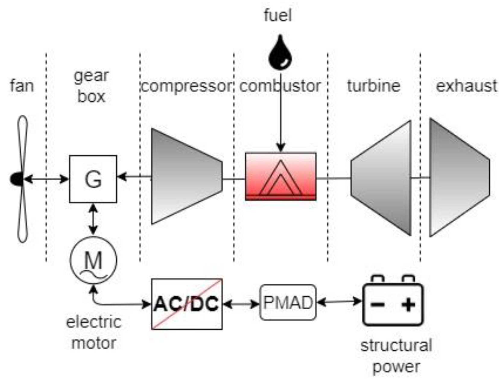
Hybrid-electric propulsion (Figure 1) represents another strategy for combining different systems’ capabilities. As an intermediate step in realising the fully electric propulsion system, hybrid-electric aircraft (HEA) integrate electric motors with gas turbines into the same designs, thereby combining combustion with electrical power to improve performance. In the turboelectric HEA, electric motors are driven by energy from turbofans which alleviates the need for battery energy storage. The engines can be downsized and optimised for cruising. Thy can operate closer to their design points during cruising, where they have maximum efficiency, than conventional engines.
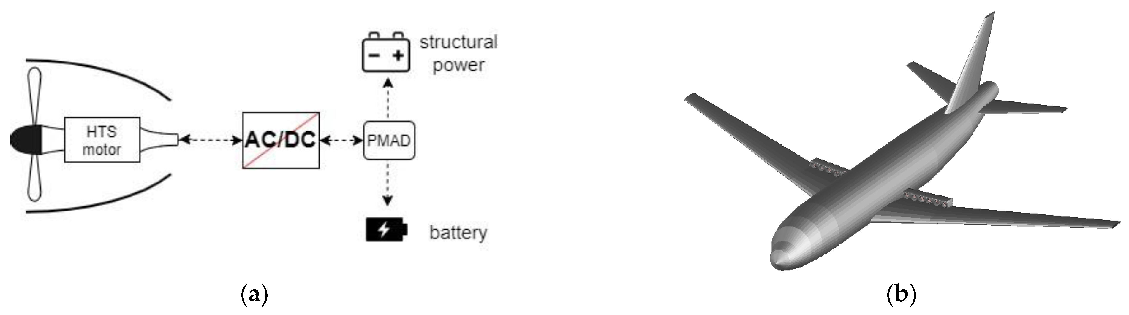
Distributed propulsion (DP) (Figure 2) represents an integration strategy that exploits the unique characteristics of electric propulsion. Figure 2 shows a potential configuration where the traditional jet engines under the wings are replaced with multiple smaller electric engines towards the trailing edges of the wings. Electric motors can be scaled down without the performance penalties that limit the scaling of gas turbines. This allows engineers to distribute thrust along the wing and thus achieve superior aerodynamic performance. Moreover, the freedom that electric motors permit regarding their scaling and integration means they can also utilise boundary layer ingestion (BLI). Boundary layer ingestion decreases the engine’s inlet flow rate. This lower flow velocity reduces the engine’s power demands and thus reduces the energy storage requirements [21]. Distributed propulsion with BLI is employed in the NASA N3-X concept [19]. The Dragon concept, on the other hand, combines a turboelectric architecture with DP integrated with the wing section to reduce drag [16].
Electric propulsion can also be coupled with aerodynamics through alternative wing designs. The BHL Ce-Liner concept utilizes a C-wing design with long C-shaped winglets to improve lift-to-drag ratio and thus decrease power and energy consumption [
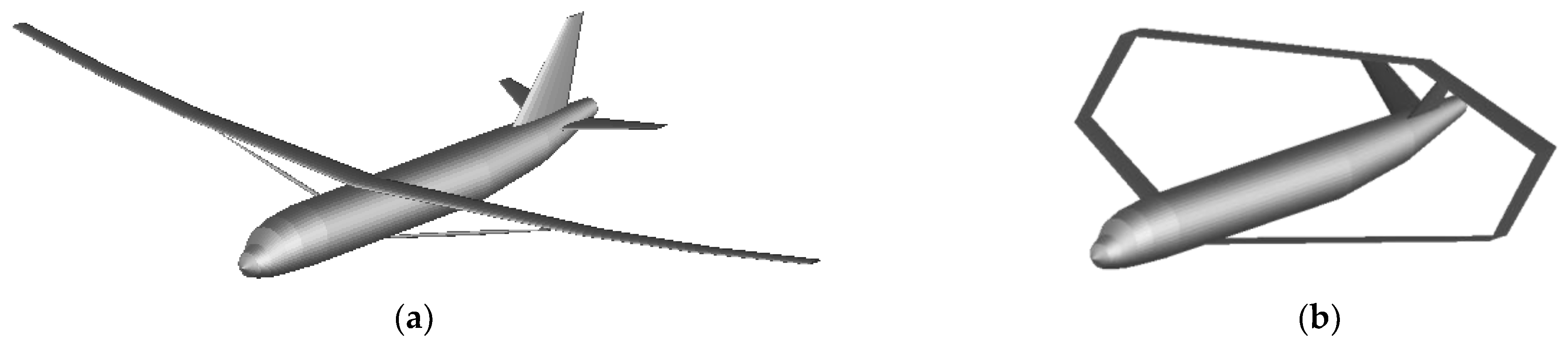
18]. Other novel wing configurations that improve aerodynamic performance include the strut-braced wing (SBW) (Figure 3a) and the box wing (BW) (Figure 3b). NASA’s Subsonic Ultra Green Aircraft Research (SUGAR) Volt concept incorporates an SBW to improve drag and minimise weight [17]. The wing–body design of the NASA N3-X is the most ambitious wing configuration which, when combined with DP, shows the greatest improvement in fuel efficiency [19]. Each of these novel wing configurations leads to different challenges in terms of optimising aerodynamic and structural performance and passenger comfort. The improvements from propulsor and airframe/wing integration highlight the potential value in exploring energy storage and airframe integration through structural power composites (SPCs).
Structural power composites (SPCs) [25] are multifunctional materials where one or more of the constituents of the material simultaneously perform(s) load carrying and energy-storing functions. For example, carbon fibres can be used to carry structural loads, store electrical energy and act as current collectors to conduct electrons. Similarly, structural electrolytes made from mixtures of epoxy and ionic liquid surrounding the carbon fibres can transfer both mechanical stresses and ionic charges. SPC technology has been developed over the last two decades, and its main advantages over existing systems are the potential for considerable systems-level mass and volume savings [26], which are becoming increasingly important for many applications such as surface and air transport and consumer electronics. Structural power composites can be further categorized by the type of electrical energy storage device. The two types which receive the greatest attention are structural battery composites (SBC) [27,28] and structural supercapacitor composites (SSC) [
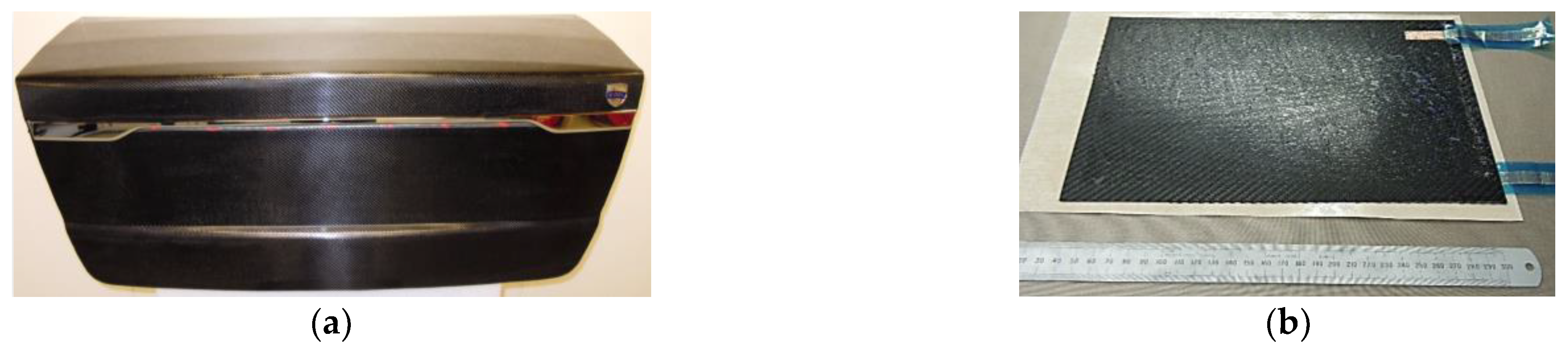
29]. SPC technology has been demonstrated in full scale automotive structures (Figure 4a) incorporating SSCs (Figure 4b) to power the rear lighting.
SPCs offer an additional or alternative solution to meeting the high electrical energy demands of AEA. Structural power reduces the parasitic weight penalty of traditional batteries and hence mitigates the high energy density requirements. Thus, SPCs potentially enable AEA which were previously considered unachievable or require alternative fuels such as liquid hydrogen. Although the technological, economic and environmental prospects of large AEA have been assessed in previous studies [15,31], such studies have not considered the adoption of SPCs in the aircraft. The study reported here investigated the potential impact that an SPC airframe would have on the design of future commercial aircraft. The electrochemical performance requirements of the SPC were evaluated for different aircraft configurations, including configurations previously regarded as non-optimal. The investigation was concluded by assessing the environmental impacts of the designs considered.
Introducing SPCs into aviation is especially challenging due to certification issues, including fire resistance, damage tolerance and cyclability [25]; however, the development of predictive modelling [32] may help to address these issues. SPCs are still emerging technology, but the prospects they can offer will have profound implications for the aviation industry. The mass savings resulting from the integration of SPCs, as confirmed by various studies concerning their integration in electric vehicles [33], are a very attractive feature for aerospace applications. Electric aircraft range increases of 11% to 66% have been predicted if a battery could be substituted with SPCs in airframes [34]. The structural electrolyte in the SPC may mitigate issues associated with separator shrinkage and short-circuiting [35] at low temperatures, and therefore may offer superior fire-resistance to that of batteries [34]. Distributed energy storage using SPCs may offer different thermal management options and may self-passivate in the event of a fault or penetration. Moreover, SPCs can offer localization of power sources, which has the potential benefits of increased safety and further reductions in wiring and cooling system masses.
Studies on early adoption routes for SPCs in conventional aircraft have considered powering auxiliary systems such as those in the aircraft cabin. Replacing the floor panels of the cabin with SPCs that would power the in-flight entertainment system has been modelled, demonstrating that mass saving of over 260 kg per aircraft (approximately 2% of the maximum payload mass on the A220-100) could be achieved if the SPC could meet specific energy, specific power and in-plane elastic modulus targets of approximately 144 Wh/kg, 300 W/kg and 28 GPa, respectively [36]. A feasibility analysis of SPC integration for small electric aircraft focused on replacing the structures within the Airbus E-fan 1.0 and Bristol Eco-Flyer, both two-seater AEA, with SPCs [37]. A specific energy of 52 Wh/kg and specific power of 103 W/kg would be required for the SPC to fully power the aircraft. A higher specific energy of 122 Wh/kg could increase endurance by 31%. A more detailed structural analysis considering the adoption of structural batteries in a four-seater general aviation aircraft with a serial hybrid-electric propulsion (Hybris) presented a procedure to size an airframe based on a weight-optimal approach [38]. In contrast, the study reported here considered such analyses on large commercial aircraft together with slender wing and electric propulsion system configurations.
SPCs have the potential to replace batteries and improve the system-level performances of aircraft. However, perhaps more critically, SPCs are such a profoundly different way to power aircraft that they warrant rethinking the traditional approach to conceptual aircraft design. Instead of bracketing the design of different systems within the aircraft, a more integrated approach will be essential to enable novel, disruptive aircraft configurations using SPCs and slender wings to reduce drag. For internal combustion engine aircraft, a drawback of slender wings is that there is a significant reduction in the fuel tanks’ total volume inside the wings. For SPC airframes, there may be no (or less) need for fuel tank (or battery pack) volume; hence these slender wing configurations both facilitate efficient electric aircraft designs and are synergistic with an SPC airframe.
Since SPC adoption presents significant challenges, the first step is to assess the feasibility of using SPCs for this application. The aim of this study was to adopt a system-level approach and exploit the synergy between the airframe and the power system of future large aircraft using SPCs. Due to the current low level of maturity of SPCs, the performance of existing SPCs was not used as a constraint, but rather the performance requirements were prescribed from the analysis. Ultimately, the main aim was to guide research efforts to the performance levels that need to be reached if SPCs are to be integrated into large commercial aircraft. A secondary aim was to provide insights into potential adoption strategies for these materials that are unconstrained by the current performances of existing materials.
This multifunctional design study focused specifically on the electrification of large civil aircraft. Since both technologies, SPCs and electric propulsion for large aircraft, are projected to mature over the next thirty years, it was fitting to analyse them in the same context. However, we do not present comparisons against either hydrogen or alternative fuels because there are still many unknowns regarding issues such as cryogenic storage and carbon capture. Furthermore, SPC technology could potentially be used, not only as an alternative, but together with other low carbon technologies, such as hydrogen or sustainable aviation fuels, to improve fuel efficiency. Conceptual designs of future aircraft configurations are outlined herein to identify the role structural power could have in developing those concepts further. By outlining the potential and the limitations of structural power for future aviation, definitive goals can be set for the further development of the technology.

2. Materials and Methods

The modelling methodology entailed five stages. The first stage involved selecting an appropriate reference aircraft to be redesigned with an SPC airframe and electrified propulsion. Secondly, a performance model was developed to estimate the power and energy required to complete a predefined mission. Thirdly, the performance model was adapted to hybrid-electric and all-electric propulsion systems and for various wing configurations. Fourthly, the masses of structural composites eligible for substitution with SPCs were estimated. Finally, the required specific energy and power density of each SPC airframe configuration were evaluated. The results of the analysis were used to assess the economic and environmental impacts from the adoption of an SPC airframe. The limitations and caveats with using these materials were also evaluated.

2.1. Baseline Aircraft

Most of the existing AEA designs focus on smaller aircraft containing up to ten seats, largely due to current battery technology limitations. To assess the potential of an SPC airframe in larger scale AEA designs, a single-aisle airliner was selected. Such narrow-bodied aircraft have substantial amounts of structural mass which could be replaced with SPC compared to smaller configurations. Such aircraft also have lower power demands than wide-bodied aircraft due to their lighter operational weights and shorter ranges. The Airbus A320 was selected as a reference aircraft based on its size and widespread use in the civil aviation industry. In their global market forecast, Airbus predicts that 76% of all new aircraft deliveries by 2038 will be single-aisle aircraft, which include A320, A319 and A220 models [39]. The A320 is the most demanded configuration by airline carriers and a 175-seat cabin is forecast to comprise 30% of the total new deliveries, representing the largest share. In this study, the A320 was used to provide baseline values for operational empty weight (OEW), maximum take-off weight (MTOW), dimensions and performance. The A320-200 series with the CFM56-5A3 engine (118 kN thrust rating) was modelled, and the parameters used in the analysis are provided in the following subsection.

2.2. Mission Profile

A mission profile for a regional jet aircraft was adopted as a foundation for the power and energy calculations. The overall modelling methodology followed the sizing workflow shown in Figure 5, and the mission profile and key aircraft specifications are shown in Figure 6a and Table 2. For the loiter stage, a turbine engine airliner is required to carry additional fuel for a flight of 30 min at holding speed and 457 m (1500 ft) altitude [40]. The payload of the mission consists of the 175-passengers, their luggage and six flight crew members. The average passenger mass including baggage is 90 kg [41], giving a total payload of 16.3 t. The total energy of the mission was determined by the flight range, and the climb rate set the maximum power requirements. The A320 has a design range of 6100 km. However, over 80% of the routes the aircraft flies are equal to or less than 1500 km long [39]. To minimize the energy requirements for the SPC airframe while maintaining high utility of the design, 1500 km was set as the design range. Where applicable, this model assumed an electric rather than a kerosene-driven aircraft, such that the total mass did not change during the mission.
The power requirements and energy consumption of the design missions were evaluated as a first step in assessing the SPC airframe. The performance of each mission segment was determined from flight mechanics principles. An SPC aircraft should be able to reach, or ideally surpass, the performance of a conventional design, in addition to providing environmental benefits. The propulsive power, P, required for level flight is P = T × V∞ = D × V∞, where V∞ is the free-stream velocity, and T and D are the thrust and drag forces. For climbing, an additional term was added to the power equation to account for the vertical velocity component RC × W, where W is the aircraft weight at the beginning of the climb stage and RC is the rate of climb or the climb gradient.
The drag force was D = (1/2)ρV∞2CDS, where the total drag coefficient could be split into zero-lift drag and induced drag CD = CD0 + CL2/(πeAR). In level flight, the lift coefficient is CL = 2W/(ρV∞2S). The zero lift-drag; CD0, the aspect ratio, AR; and the Oswald efficiency factor, e, are all parameters determined by the wing geometry and baseline configuration of the A320. The value of CD0 depends on the flap and slat configurations during the different flight stages and can be estimated using the component build up method [42]. A more comprehensive and robust methodology for drag polar estimation of modern aircraft [44] was used for the purposes of power calculations in this analysis. The drag values for an A320 found by this method [44] are presented in Table 3. The Oswald efficiency factor for the A320 was set to e = 0.78 for all flight stages [45]. The required propulsive power needed to complete each mission segment can be expressed as:
P = 1 2 ρ V 3 C D 0 S + 2 W 2 ρ V S π e A R + R C × W .
The final value of the power required from the propulsion system of the aircraft is subject to the efficiency, ηp, of the propulsive system, such that Preq = ηpP. Turbofans currently in service can reach propulsive efficiency up to ηp = 0.8 and an overall efficiency of fuel to propulsor of ηo = 0.35 after fuel combustion thermal losses [46]. The energy, E, is given by E = Pt, where t is the time taken to complete the mission segment.
The take-off (Figure 6b) is the first leg of the design mission and its performance was analysed in accordance with EASA certification specifications for large aircraft (CS-25) [47]. CS-25 defines the take-off as the period between acceleration from zero speed on the ground to the point, at which the aircraft has climbed to a height of 11 m from the runway surface. To calculate the power and energy requirements, the take-off path was split into ground roll and transition to climb. The take-off velocity has a safety value of V2 = 1.13Vstall for a fly-by-wire aircraft [43,47]. The stall speed was estimated from level flight force equilibrium and was subject to the value of CLmax for take-off and the MTOW. An empirical estimation of CLmax = 2.6 [48] is used for a flat/slat configuration such as that of an A320 wing. The resulting take-off speed was then V2 = 62.6 m/s and the typical A320 V1 = 74.6 m/s. The rotational velocity was approximately VRV2. Given these velocities, the power could be calculated from Equation (1). The take-off time was next estimated to find the energy requirements. The ground roll time, tgr, i.e., the time for the aircraft to accelerate to lift-off, derived from force equilibrium, is:
t g r = V 0 V 1 W g T D + μ L W d V
The rolling coefficient of friction, μ, for a standard dry asphalt/concrete is 0.03 [49], and the thrust at take-off is 93% of the maximum A320 engine thrust [50]. Equation (2) was solved numerically using the trapz function in Matlab.
The second stage of take-off starts from lift-off and ends after climbing to 11 m above ground (Figure 6b). The time taken, ttr, was calculated as ttr = 11/(tanγV2), where the rotation angle γ was constrained to 12° to avoid tail strike [51]. The conventional A320 climb performance from empirical data and the A320 Flight Crew Operating Manual is shown in Table 4. The second climb stage is the most demanding in terms of power and thus governs the specific power of the energy source. The power requirements for each of the four climb stages were estimated, and the energy was then determined based on the climb times. The cruise and loiter segments represent the biggest portions of the total energy consumption for a mission. There is no vertical velocity component during these stages, and the power demand was calculated for the clean configuration at the target cruise speed. The loitering speed of the A320 is 118.3 m/s [43].
The descent was modelled similarly to the climb stage. The descent performance of an A320 is summarized in Table 5, where the rate of descent, RD, is -RC in Equation (1). Only the first and last descent stages were powered due to the steep descent angle of the second stage. To analyse the landing requirements, the landing path was split into flare and deceleration, mirroring the transition and ground roll phases of take-off. The flare time is defined as the period of descent from 11 m altitude to touchdown [47]. The flare time, tflare, was calculated as was ttrans for an A320 pitch angle at touchdown of γ = 8.7° [51], and a velocity of Vlanding = 70.5 m/s [43]. Equation (2) was used to estimate the time to decelerate to taxiing speed after touchdown. The new integral limits were then Vlanding and Vtaxi = 10.3 m/s, the A320 taxi speed limit [43]. The breaking friction coefficient was set to 0.35 [52] and the thrust for idle engine during landing was 23% of the maximum thrust [50].
In addition to this mission profile, the energy and power requirements during taxiing were included; 7% of the maximum thrust was considered to be used during taxiing [53]. For a taxi time set to 20 min and Vtaxi = 10.3 m/s, the power and energy were calculated from Etaxi = Ptaxi ttaxi, where Ptaxi = Ttaxi Vtaxi. Finally, the model included non-propulsive power and energy demands from electrification of the subsystems. These non-propulsive demands depend on the subsystem architecture. The subsystems of A320 aircraft are powered by pneumatic, hydraulic, mechanical and electrical power. For a conventional aircraft, non-propulsive energy typically represents 5% of the total energy of a mission [54].

2.3. Electrical Requirements

A numerical model was formulated to calculate the maximum power requirement and total energy based on the take-off weight (TOW) and mission profile of an A320 using a Matlab script to compute the flight mechanics analysis detailed in Section 2.2. This model was applied to a conventional A320 design and validated against existing studies, as follows. The take-off weight of the baseline A320 included the OEW, payload and fuel. The fuel requirement to complete the design mission profile was approximated from empirical weight fractions for a civil jet. The fuel consumption during cruising and loitering was estimated for the lift-to-drag ratio, L/D, and specific fuel consumption, C, of A320 wings and engines, using the Breguet range equation [42], R = (V/C) (L/D) ln(Wi/Wf), where R is the range, V is the velocity, Wi is the initial aircraft weight and Wf is the final aircraft weight after the mission segment has been completed. The final fuel weight included a 5% contingency fuel, as per ICAO regulations, resulting in a total of 5.7 t for a 1500 km mission. The TOW for the design mission was then approximately 65 t. For the estimated take-off weight and range, the energy and power demands are presented in Figure 7.
Model validation was performed using the overall efficiency of a turbofan and the total mission energy. A separate study [22] has estimated a peak power demand of 21 MW and a total energy of 32 MWh for an A320 on the same mission range; the slightly higher peak power is attributed to a heavier take-off weight. The mission performance model was also compared to the data in the A320 Flight Crew Operating Manual (FCOM) [43]. The mission time and fuel efficiency agreed with those from the FCOM for all flight stages. Consequently, the outputs of the model were deemed to provide reasonably accurate values for the A320 energy consumption and peak power demand. Following the baseline model, the script was updated to model the energy and power demands for the MEA, HEA and AEA configurations. Details of the design changes associated with these different electric aircraft configurations are provided in Appendix A. The major differentiating factors were the differing take-off weight and weight changes throughout the mission profile.

2.4. Structural Mass

An A320 is composed of around 20% composite materials by weight; only a small portion of which are carbon fibre reinforced polymer (CFRP) composites. The A350 XWB model has 53% composite materials by weight [55]. While most of the fuselage structures are made from CFRP, heavy load frames such as the landing gear and the pylons are still manufactured from metal alloys. Even monofunctional composite materials still face predictive modelling issues, particularly in relation to compressive strength failure mechanisms and damage tolerance. Certification is therefore a major challenge, and much of the current research is focused on overcoming this hurdle.
Structural masses are shown in Table 6. The total structural masses from two independent sources agreed to within 1% [56,57]. To determine minimum specific energy and specific power requirements, an approximate total structural mass of 25 t was considered as being representative of the maximum mass that could be replaced with SPC.
A fully composite A320 airframe would have a significantly different mass. Replacing just the fuselage of an A320 with CFRP is predicted to decrease the component’s mass by over 27% [58]. However, since the idea of this study is to replace the airframe with SPCs, the implications for mass savings will be different. SPCs with poorer mechanical performance relative to conventional composites could be used to make thicker structures to achieve the required mechanical properties. For example, if an SPC has 80% of the structural performance of a CFRP, the thickness and energy stored in the SPC could increase by 25%. This analysis assumed that the mass savings of a composite A320 airframe would be offset by the increased thicknesses of SPC structures. The weight of an SPC cooling and management system was not considered. Since the energy in SPCs is more sparsely distributed than that in batteries, the cooling required for SPCs may be less than that needed for batteries. Ultimately, the goal was to not exceed the conventional airframe mass significantly, to maintain the benefits of using SPCs instead of batteries.

2.5. Slender Wings

The final difference between the baseline aircraft and the SPC airframe that was assessed in the current study involved the wing configuration—specifically, slender wings to reduce drag. The aim of this section is to provide high-level understanding of the relationship between novel wing configurations and the SPC airframe in terms of energy demands. The direct impact of the MEA and HEA configurations is a lower MTOW which allows for smaller wings. An alternative approach is to couple wing and SPC design through modelling the energy demands for novel wing configurations whilst maintaining the original TOW. The alternative wing configurations were sized to reach the same mass as the conventional wing. The aspect ratio, Oswald efficiency factor and zero-lift drag were the wing geometry factors affecting the performance.
The two slender wing configurations that were considered for the SPC airframe design were the strut-braced wing (SBW, Figure 3a) and the box wing (BW, Figure 3b). The former is a thinner wing of longer span or higher aspect ratio that is structurally supported by a strut. The system-level effects of an SBW are reductions in induced drag and weight. An alternative version of the SBW is the truss-braced wing, where several additional structural members can be attached between the wing and the strut. The advantages of adding structural attachments are an increase in flutter speed, a decrease in overall wing weight and attractive fuel efficiency increases [59]. The SBW can potentially be optimised to decrease the energy demands through improved aerodynamic performance whilst maintaining the weight of a reference cantilever beam. This new optimisation strategy, which does not focus on minimising weight, would relate the SPC and SBW design. The SBW was sized based on a methodology that was verified against the SUGAR Volt design [60]. The aspect ratio of an SBW has been shown to increase from 10 to 16.6 at no weight penalty compared to a cantilever wing [60]. Other studies have shown similar increases in aspect ratio [61]. Maintaining the same aspect ratio was expected to lead to weight savings for the SBW. For the A320 wing in AEA configuration, the aspect ratio was increased to 16 whilst maintaining the same surface area and mass.
The box wing configuration has improved structural and aerodynamic performance as well. Distributing the load between the aft and the fore wing in the BW results in a different moment distribution. The box wing has been shown to offer a lower bending moment and shear force which can relieve constraints in the design of multifunctional composites for the skins, spars, stringers and ribs of the wing [62]. In terms of aerodynamics effects, the induced drag can be reduced by up to 20% compared to conventional wings because of the higher aspect ratio and Oswald efficiency [60]. The box wing can be designed to be slightly heavier or lighter than the conventional wing depending on the optimisation parameters. The BW was sized assuming that the aerodynamic load was equally distributed between the fore and the aft wing as per the biplane theory [62]. The two wing surfaces were sized to be of equal surface area, and their total surface area to be equal to that of the conventional wing. The box wing has a higher efficiency and lower zero-lift drag than the conventional wing. Various theoretical and CFD studies have estimated an Oswald efficiency of 0.97 for the box wing with up to 14% lower glide ratio, both dependent on the stagger ratio—that is, the ratio of height-wise spacing of the two wings to the span [63]. For the geometry of the A320 wing, the stagger ratio was set to 0.2 [63].
The final wing designs (Figure 3) were employed in the AEA and HEA configurations. In both cases, further studies need to be performed to account for the overall effect on drag. The overall wing geometry variables (Table 7) were calculated from theory and OpenVSP [24], and then used to calculate the energy and power consumption of the missions. The SBW would experience penalties in zero-lift drag and Oswald efficiency due to the decreased chord lengths [42]. A slightly larger surface area was considered for the BW configuration due to the wingtip section.

2.6. Impact on Aviation

The motivation behind developing electric commercial aircraft is to minimise emissions. Zero direct-flight emissions are a definite consequence of the AEA, but the overall environmental impact [15,31] depends on the source of electricity. The energy supply chain needs to be followed to assess the environmental impact of the aircraft configurations designed. Depending on the source of electricity generation, the overall AEA emissions can be very different. The total emissions were evaluated per flight and compared to those of the conventional A320. The starting point was to identify the different electricity sources and their fraction of the total electricity generated. The CO2 and non-CO2 emissions per watt-hour produced were then evaluated, including any losses in energy transfer. Similarly, the emissions per kilogram of jet fuel burnt were calculated.
The future electrical grid was modelled using the European Commission (EC) reference scenario for the energy grids of the European Union members [64] and how the electricity generation split is projected to evolve up to 2050 (Figure 8). The increase of the renewable energy sector and the reduction of coal electricity generation is expected to reduce the carbon intensity per unit electrical energy from the grid significantly.
The emissions per flight were estimated based on the greenhouse gas (GHG) intensity per unit energy from the grid, which includes all greenhouse gases emissions that are a by-product of electricity generation [15]. By the time the AEA can be introduced into service, the emissions intensity of electricity will have dropped drastically (Figure 9a). However, these emission intensity values would be very different depending on the region or country where the AEA are charged. Charging in India and China would result in over three times higher emissions [65], which thus places a strong emphasis on the efficiency of aircraft management and operations.
The CO2 emissions from the aviation sector as projected by ICAO [2] are shown in Figure 9b. Under a business-as-usual scenario, with only moderate advancements in fuel efficiency, emissions are expected to triple by 2050, whereas more optimistic assumptions suggest emissions are significantly lower. Both scenarios emphasize the need for more disruptive design innovations if green aviation targets are to be met. ICAO estimates that 3.16 kg of CO2 is emitted for every kg of jet fuel burned [2]. The greenhouse impact of non-CO2 aviation emissions is difficult to predict, and there is uncertainty in how to measure this impact. The emissions per flight for the conventional A320 were calculated by assuming that 2.58 kg of non-CO2 GHGs are emitted for every 1 kg of jet fuel burned [15]. Electricity transmission efficiency and battery charging efficiency were accounted for in the calculations.

3. Results and Discussion

This section presents the results and corresponding discussion related to five analysis topics: (a) more-electric (Figure A1), (b) hybrid-electric (Figure 1) and (c) all-electric aircraft (Figure 2b); (d) slender wing designs (Figure 3) and (e) environmental impact.

3.1. More-Electric Aircraft

The MEA with an SPC airframe would need 5.6% less fuel than a conventional A320 and 4.9% less fuel than an MEA using engine generators and no electrical green taxiing system (EGTS). For comparison, fuel savings of 3.5% have been calculated for a 5556 km mission [66]. The EGTS would result in overall fuel efficiency improvements only when powered through structural power. For the MEA without an SPC airframe, the EGTS would lead to a slightly larger amount of fuel being burnt during flight. If a 40 kg battery were to power the EGTS, instead of the auxiliary power unit, that would lead to overall savings and zero airport emissions [67]. However, such a battery would need to have an energy density of 417 Wh/kg to power the 20-min taxi phase, which is about 2.5 times larger than the current Li-ion battery pack-level energy density of 170 Wh/kg [11]. In addition, there would also need to be a local supercapacitor to meet the high power demands. As the landing gear housing is tightly packed, the volume that would be needed to accommodate the EGTS is also a design challenge. Structural power composites could power the system with minimal added volume and localise the power source, thereby reducing the amount of wiring needed. Forming the panels around the landing gear housing from SPC could also reduce high energy density requirements and enable the design of a self-contained taxiing system that is safer and could be easier to maintain and repair.
Removing the hydraulic system would lead to both mass savings and more available volume within the airframe. Removing the three main hydraulic reservoirs of the A320 would free up 33 L of space and removing the largest diameter hydraulic pipes would result in over 180 L of space saved [43]. This extra space can be used to accommodate new systems or electrical components related to the SPC. The estimated mass, volume and fuel burn savings that an MEA SPC airframe could achieve compared to conventional A320 were >1100 kg, >210 L and 5.6%, respectively.
The specific energy and power requirements of the MEA SPC airframe can be met by adjusting the proportion of airframe structural mass that is substituted by SPCs (Figure 10). For example, a 50% SPC airframe, corresponding to the composite composition of state-of-art airliners, would need E* = 90 Wh/kg and P* = 55 W/kg. These values are approaching feasibility for the state-of-the-art SPCs [68,69]. The maximum power requirement corresponds to all subsystem electrical loads applied at once: for most of the flight, these power demands are much lower. Therefore, structural battery composites could be used for most of the operating conditions. Structural supercapacitor composites could be used in flight control surfaces and landing gear actuators where there are high power requirements for short periods. An integrated design of the electro-mechanical actuators and electro-hydrostatic actuators using SSCs could minimise efficiency losses and wiring mass.

3.2. Hybrid-Electric Aircraft

The HEA A320 with electric subsystems, as with the MEA design, was calculated to have a mission fuel burn of 4.0 t. The significant improvement in fuel efficiency for the HEA (Table 8) was a result of the electric motors producing propulsive power throughout the whole mission, excluding landing and take-off, due their much lower energy consumption (Figure 11a). Most HEA concepts have the electric motors switched off during cruising, as the motors would require too much additional battery power and remove any fuel efficiency benefits. The emphasis here is on developing more powerful and efficient electric motors that could undertake a larger portion of the power demand during take-off and climbing and allow scaling down of the turbine. High-temperature superconducting (HTS) motors, even at the lower spectrum of performance projections, would result in notably higher fuel savings when employed during cruising.
The required E* of a fully SPC airframe for different levels of HTS cruise power setting (Table 9) is close to that of current Li-ion batteries. The required performance for the SPC airframe can be lowered if the HTS motors operate at lower power settings during cruising. Even if the HTS motors are switched off during cruising, the fuel saving with an SPC airframe would be over double that of the 7% fuel efficiency improvements for other A320 HEA designs in the literature [70,71]. Alternatively, batteries could be added. Figure 11b shows how the SPC E* requirements vary for future batteries for a 1500 km mission. Even with an additional 7.5 t of battery mass, the HEA design would have 17% better fuel efficiency than the conventional A320. However, unless the batteries’ E* is much higher than 400 Wh/kg, adding batteries would not significantly lower the performance targets for the SPC airframe, whilst introducing issues with their onboard accommodation, thermal management and safety. A potential design zone to target for 1500 km HEA might be that shown in the red box in Figure 11b—for example, a 200 Wh/kg SPC airframe with 5 t of 600 Wh/kg batteries. The SPC E* target, which matches the performance of existing Li-ion batteries, could be considered a plausible stretch target, given that a 131 Wh/kg [72] (260 Wh/L, 12.1 N m2 bending rigidity, 9.6 GPa elastic modulus [73]) structural battery has been experimentally demonstrated and a 160 Wh/kg (330 Wh/L) structural battery has been calculated to be producible by tripling the stack thickness. The battery targets may be achievable using known, but not yet widely implemented, chemistries, such as Li-S [74,75] or Zn-air, with which 523 Wh/kg [76] has been experimentally demonstrated and over 700 Wh/kg has been projected [77].

3.3. All-Electric Aircraft

Once the propulsion system had been sized, the potential impact of an SPC airframe was assessed by calculating its effect on the E* requirements. Even with a 5 t reduction in MTOW for the AEA due to the lighter propulsion system, an SPC airframe would require an energy density of around 1000 Wh/kg for a 1500 km mission. Given this high value, it would be beneficial to supply some of the energy using batteries to reduce the SPC E* requirements. The battery mass was limited to 23 t, to keep the total mass below the MTOW of an A320. The landing gear and control surfaces would need to be resized if a greater battery mass is needed.
For both the 1000 km and 1500 km missions, increasing either the mass of the batteries or the specific energy of the batteries led to a linear reduction in the SPC specific energy requirement (Figure 12). A range of 1500 km or greater is very energy demanding and would require a large mass of batteries, even with an SPC airframe. For the 1000 km range (Figure 12a), the lower energy demands lead to more achievable targets. Li-air batteries have been projected to reach cell-level specific energies of 950 Wh/kg [11], and a useable pack-level E* has been estimated to initially be 900 Wh/kg (700 Wh/L), dropping linearly down to 680 Wh/kg (530 Wh/L) after 200 cycles [78]. Therefore, a potential design zone to target for 1000 km AEA might be that shown in the red box in Figure 12a—for example, a 400 Wh/kg SPC airframe with 17 t of 700 Wh/kg batteries. Assuming batteries supply two-thirds of the power, a maximum SPC P* ≈ 300 W/kg would be needed during climbing. Power demand was not considered to be a constraint at this stage, as SSC components could be added at later design stages to meet climbing power demands.
For a 1000 km range AEA without an SPC airframe, 36 t of 680 Wh/kg batteries would be needed. The volumetric fuel capacity of the current A320 is 27 kL; hence even with 530 Wh/L (pack-level) Li-air batteries [78], there would not be enough space in current airframes for 46 kL of batteries plus their cooling system. Since SPCs could reduce the battery mass needed, an AEA design with an SPC airframe could provide a solution to these volume constraints. Another potential consequence of an SPC airframe is increased safety. Carrying half the amount of high-energy-density batteries could lower the risks of catastrophic incidents, such as explosions on the runaway.

3.4. Slender Wings

Both slender wing configurations with the AEA design significantly decreased the energy demands on the batteries and the SPC airframe (Figure 13) compared to those for the conventional-winged AEA A320. The BW and SBW designs led to decreases in energy demands of 6.7% and 11%, respectively. For the HEA A320 configuration without batteries, the BW and SBW would result in 29% and 34% fuel efficiency improvements, respectively, compared to the baseline conventional A320. The constraints on the SPC airframe remain constant, as they depend on the power output of the HTS motor. The slender wing designs enable either reductions in the mass and volume of batteries or lower E* requirements for SPCs and/or batteries. Potential design parameters for a 1000 km AEA might be targeted within the red boxes shown in Figure 13. For the SBW design, a 400 Wh/kg SPC airframe with 12 t of 700 Wh/kg batteries, the batteries would occupy half of the original A320 fuel tank’s volume.
The drag, and therefore, the energy requirements, could be reduced by using computational fluid dynamics (CFD) as a tool to more precisely develop and refine the aerodynamic design of the wings. The results indicated that the SBW had a more significant impact on mission energy expenditure than the BW. However, the trade-off between structural and aerodynamic performance may make the BW more attractive for an SPC airframe. Further research involving a detailed structural analysis is recommended to determine which wing configuration would be more appropriate for an SPC airframe. Additionally, a blended wing–body configuration warrants investigation but would involve a complete redesign of the reference aircraft, which was not within the scope of the present investigation.
An issue with both the BW and the SBW configurations is the engine mounting [63]. The large turbofans of conventional aircraft present challenges for the slender wings. For the HEA, the two turbofans can be mounted to the back of the fuselage to avoid complicating the design of the novel wing configurations. For the AEA, the DP configuration makes fuselage mounting less likely. However, since the DP is much lighter, mounting would not be such a constraint for the structural integrity of the wings. The ducted fans could be fully integrated into the BW as in the Dragon concept [16]. There are many possibilities for the optimal configuration; and further research into combining wing structural and aerodynamic analysis, and engine integration with SPC design, would be very beneficial for realising future green AEA.
The majority of past and ongoing research concentrates on the design of the SBW through optimising the strut or attachment points and integrating that design into conventional aircraft [79]. These studies are mostly short-term projects and even the multidisciplinary studies are limited to conventional aircraft, except for the SUGAR Volt project [17]. Considering the level of maturity of slender wing designs, it may prove more fruitful to continue their development in the context of AEA objectives, rather than limiting their research to discipline-specific objectives that would then need to be adapted to the full aircraft configuration. These wing configurations could be utilized in AEA design to reach feasible performance requirements for cleaner energy storage systems. Future research should investigate the mechanical performance requirements of an SPC airframe using slender wing designs together with distributed propulsion integration strategies. Future research could also investigate whether using SPCs to provide part of the energy storage would enable simpler non-battery solutions to supply the remaining energy. For example, using hydrogen fuel cells instead of developing hydrogen combustion engines and/or using gaseous instead of liquid hydrogen [80].

3.5. Impact on Aviation

The emissions per flight were estimated for all the configurations without slender wings (Figure 14a,b) and the emissions for slender wing configurations in AEA (Figure 14c,d). From the configurations considered in this study, only the AEA configurations could potentially reduce operating CO2 emissions by 75% relative to the conventional A320. MEA and HEA showed much lower impacts on GHG emissions than AEA, but their effects on local air quality near airports are important. Depending on the mission range and the country of charging, the advantages of an AEA over a conventional aircraft might not be exploited. For the AEA-800 MIT design, operating a 926 km mission using the current energy grid scenario in the US, little to no improvements in emissions have been estimated compared to conventional A320 [15]. Depending on the battery energy density and the energy grid scenario, the GHG emissions for the MIT design can even be higher than those of conventional aircraft. Consequently, the environmental impacts of future aviation are not only in the hands of aircraft and electrical engineers, but also rely on airline operations and electricity grids transitioning towards renewable energy sources.
The full life-cycle emissions from batteries and SPCs [81] are important to consider, as both composite and battery production and disposal have high GHG intensity. A full life-cycle assessment is not yet possible for the SPC airframe, since the detailed chemistry, material design and structural architecture are not yet known. The SPC airframe would most likely consist of a variety of SBCs and SSCs, with differing lifetimes depending on the types of load-bearing structures they represent and the types of electrical components that they power. The production of a 121 Wh/kg Li-ion battery has been estimated to emit up to 15 kg CO2 equivalent GHG per kg battery produced [82]. If the emissions per kg of battery produced were to remain constant, around thirty-two missions would produce the CO2 equivalent GHG emissions from the production of 12 t of batteries for a SBW all-electric A320. Since a large portion of production emissions is due to electricity consumption, the country of production is of great significance.
At their end of their service lives on aircraft, when the charging properties have degraded, the SPCs and batteries could be re-purposed and reused as non-structural battery packs in less demanding stationary applications [15]. Recycling the SPC airframe could reduce production costs, since a quarter of the production emissions of Li-ion batteries due to electricity consumption can be reduced by recycling the anodes and cathodes [83].
Minimising noise emissions is another objective of commercial aviation. Aircraft noise depends on the thrust rating, the speed of the propulsion system, the MTOW, the flight controls and the landing gear [84]. Noise predictive modelling is a complex process that requires a detailed propulsion system analysis and CFD simulations; both analyse are outside of the scope of this study. For an all-electric A320 with six ducted fans, a 15% reduction in sound levels of take-off and landing noise contour distance has been calculated [22]. The noise of the final baseline AEA design could be lower for the slender designs, depending on the fan integration method. At this stage, it is unclear whether Flightpath 2050s [5] noise goals can be achieved.
Airline operations of AEA or even HEA would be very different to those of conventional aircraft. New daily flight operations, maintenance schedules and checks need to be developed and certified. The daily utility of a current A320 airliner translates to roughly four flights under 1500 km a day [39]. The average turn-around time of 45 min for single-aisle aircraft [85] would require charging of the batteries or SPC airframe at a charge rate of (4/3)C in battery C-rate terms. This charge rate does not exceed the maximum charge rates that are safely accepted by batteries used in existing electric vehicles of 1–1.5C [86]. Faster charge rates are expected to be achieved of around 3C [86], and recent research has developed batteries that can recharge in 10 min [87].
The useful life of an aircraft with an SPC airframe could potentially be much lower than that of a conventional aircraft. Composites with electrochemical properties may have shorter lives than the materials of current aircraft due to capacity fading during storage and during cycling. Replacement of the SPC airframe components could potentially be costly, and therefore adoption of SPC technology is likely to begin with easily replaceable structures. Although the production costs of an SPC airframe would be higher than those for a conventional airframe, the costs may be lower than the total production costs for the separate monofunctional structures and batteries, since less overall material would be processed and only one production facility would be needed. The costs would be highly dependent on the production scale; scaling up SPCs would reduce the costs considerably, as with batteries. Estimated costs of the required raw materials for SPCs compared with the costs for conventional composite materials are provided in [36] (Section III.G).
The principal challenge of the SPC airframe is to develop material architectures and compositions capable of storing and supplying the required energy and power whilst maintaining structural integrity and minimizing weight and cost. Apart from the issues that SPCs share with conventional composites, namely, manufacturing rate, damage tolerance and maintenance, their electrochemical properties introduce a host of additional challenges for airline operations. An SPC airframe might have a detrimental effect on the useful life of an aircraft, alongside increasing capital and maintenance costs. Moreover, overall emissions and energy costs would be dependent on the country of charging. A strong emphasis should be placed on addressing these operational and ownership challenges to enhance the economic viability of SPC airframes and their applications in large aircraft. Finally, SPC research should aim to demonstrate SPCs in small scale MEA, HEA or AEA to provide confidence to adopt SPCs in larger aircraft.

4. Conclusions

The adoption of structural power composite airframes in future electric aircraft configurations could lead to significant reductions in energy demand and emissions. A methodology was developed to estimate the specific energy and power requirements of an SPC airframe according to the mission performance and aircraft mass of an A320. The role of the SPC was assessed for three different levels of electrification: from more-electric aircraft (MEA) having electric subsystems to hybrid-electric aircraft (HEA) to all-electric aircraft (AEA). Finally, slender wing configurations in conjunction with AEA and SPCs, and the challenges in terms of airline operations, were evaluated and discussed.
The required electrical performance of SPCs was within feasible limits when combined with batteries or as a stand-alone energy source in MEA and HEA configurations. For an MEA A320, a 5.6% fuel efficiency improvement could be achieved by a 50% SPC airframe with specific energy and power of 90 Wh/kg and 55 W/kg, respectively, for a 1500 km mission. The specific energies of state-of-the-art structural battery composites already demonstrated experimentally at the laboratory scale and cell level (24 Wh/kg [68]) are approaching the specific energy target. The cell-level specific power levels of state-of-the-art structural supercapacitors, demonstrated experimentally at the laboratory scale (1.1 kW/kg [69]), exceed the specific power target. For the HEA and AEA, the entire airframe would need to be substituted with SPC to minimise the performance requirements. In the HEA configurations, specific energy and power values exceeding 200 Wh/kg and 120 W/kg would lead to improved system-level performance. The AEA configuration would need to incorporate novel wing design and distributed propulsion, in addition to batteries and an SPC airframe, in order to decrease the specific energy and power requirements to feasible levels. An AEA aircraft with an SPC airframe would require half the battery mass and could enable increased mission ranges compared to those of a conventional airframe.
This investigation has established that a large AEA having commercially attractive mission profiles could become more technologically viable by coupling novel wing configurations with engine integration and SPC development. Combining these disciplines at the conceptual design level would enable optimisation of performance requirements for each component. This study has also defined quantitative electrochemical performance targets to provide the start of the roadmap for adoption of SPCs in civil aviation. Recommended milestones for SPC specific energy values would be approximately 100 Wh/kg for adoption in MEA; 200 Wh/kg together with 600 Wh/kg pack-level batteries for adoption in HEA; and 400 Wh/kg together with 700 Wh/kg pack level batteries or other sustainable energy source for adoption in AEA. Since structural power is applicable to other vehicles, such as cars and lorries, the methodology reported in this study could be adapted and used to develop similar roadmaps for the adoption of SPCs in other vehicles.

Author Contributions

Conceptualization, E.S.G., E.K. and S.N.N.; methodology, E.K., E.S.G. and S.N.N.; software, E.K.; validation, E.K., S.N.N. and E.S.G.; formal analysis, E.K.; investigation, E.K.; resources, E.S.G.; data curation, E.K. and S.N.N.; writing—original draft preparation, E.K. and S.N.N.; writing—review and editing, S.N.N., E.S.G., M.S.P.S., A.R.J.K. and P.L.; visualization, E.K.; supervision, E.S.G. and S.N.N.; project administration, E.S.G.; funding acquisition, E.S.G., M.S.P.S., A.R.J.K. and P.L. All authors have read and agreed to the published version of the manuscript.

Funding

This research was funded by the EPSRC Future Composites Research Manufacturing Hub (EP/P006701/1), the EPSRC Beyond Structural project (EP/P007465/1), the European Office of Aerospace Research and Development (IOE Grant FA9550-17-1-0251), EU Clean Sky 2 (SORCERER Project #738085) and the Royal Academy of Engineering (Chair in Emerging Technologies).

Conflicts of Interest

The authors declare no conflict of interest.

Appendix A. Electric Aircraft Configurations

Appendix A.1. More-Electric Aircraft

The first step towards aircraft electrification is electrifying the subsystems. The conventional A320 design has many of its secondary systems powered non-electrically. In the MEA design, an electrical taxiing system was added, and all subsystems were redesigned to be powered through SPCs. The conventional A320 numerical model was adapted to calculate MEA power and energy demands, with altered the non-propulsive energy and taxiing stages.
The pneumatic system of the A320 currently powers the ice-protection system and environmental control system (ECS), hydraulic pressurisation, water reservoir and engine start [43]. These functions can all be electrically powered in a bleed-less architecture. The 787 Dreamliner has already demonstrated the many advantages of a bleed-less architecture, including reduced maintenance costs and fuel savings. The electrical load, however, is tripled, requiring more powerful engine generators and a more complex power management and distribution (PMAD) system. An alternative approach is to remove the generators altogether and power the systems through batteries or SPCs charged on the ground before departure.
Similarly, the hydraulic system can be electrified. In the A320, the flight control surface (FCS) actuation system, nose-wheel steering, landing gear (LG) actuation, wheel braking and cargo doors are all hydraulically powered [43]. Two approaches have been developed for electrical actuation: electro-hydrostatic actuators (EHA) and electro-mechanical actuators (EMA) [88]. EHAs use a hydraulic cylinder that is electrically actuated, and each actuator is a self-contained system (it is not part of system-level hydraulic power). EMAs operate using only electric motors for actuation. Such actuators are already in service on the Boeing 787 and Airbus A350XWB [88]. In the MEA A320 design, a combination of both EHAs and EMAs can be used to replace all the hydraulic and pneumatic system functions by following an integrated approach to sizing the MEA components for single-aisle aircraft [66].
With the removal of the generators, the A320 electrical system will also be powered by SPCs. The A320 electrical system powers 115 V AC and 28 V DC electric buses. The new suggested PMAD system of the MEA is illustrated in Figure A1 with some of the electrical loads shown. The ±270 V DC buses correspond to the new electrical requirements of the hydraulic and pneumatic systems. The MEA SPC airframe allows the architecture of the PMAD to be optimised according to the design objectives. Safety or weight considerations may mean a different distribution and number of the converter units, different AC and DC buses and different wiring. A comprehensive study is needed in the future to determine the optimal operational strategy of the structural power PMAD. We maintained the conventional A320 PMAD system weight of 1 t, as we assumed that any weight savings may be offset by additional cooling system requirements.
Figure A1. More-electric aircraft power distribution (adapted from [66]).
Energies 14 06006 g0a1
The MEA subsystem power was estimated to be 365 kW on average based on conventional A320 electrical demands and the additional electrical ECS and IPS loads [15,66,89]. A stable power demand was assumed through all flight stages. The maximum power requirement was estimated to reach up to 650 kW if all systems simultaneously work at maximum capacity. The PMAD was considered to be 94.5% efficient [15].
The final function that was electrified in the MEA design was the taxiing system. The electrical green taxiing system (EGTS) developed by Safran and Honeywell [90] has already been successfully tested on an A320. The 300 kg system is installed at the nose landing gear and can accelerate the A320 to its normal taxi speed [90]. The EGTS was originally designed to be powered by the auxiliary power unit (APU), but since it operates at ±270 VDC, it can easily be integrated into the MEA. Currently the benefits of EGTS do not out-weigh the additional weight penalty. However, if powered by SPCs, the EGTS could yield zero direct emissions and significantly reduce noise during taxiing. In terms of power, the EGTS can consume up to 50 kW [67].
The masses of the conventional A320 subsystems, the new masses calculated using this approach and the net mass changes for the MEA are shown in Table A1.
Table A1. More-electric aircraft subsystem mass savings (adapted from [66,91,92]).
SubsystemOriginal Mass (kg)New Mass (kg)Mass Change (kg)
Hydraulics8660−866
Electrical generators and auxiliary power unit5560−556
Bleed air2490−249
Landing gear steering and brakes760661−99
Ice-protection system309565
Environmental control system08080
Flight control surfaces and landing gear actuation772996224
Electrical taxiing system0300300
Total32332132−1101

Appendix A.2. Hybrid-Electric Aircraft

The HEA combines electrical and chemical (fuel) energy sources to increase fuel efficiency and reduce emissions. A variety of propulsion system architectures have been developed involving different levels of integration between the internal combustion engine and an electric motor. The main challenge of HEA design is compensating for the added system complexity and mass. The three main designs explored by engineers are series, parallel and turboelectric architectures [7]. In the series configuration, power from the gas turbine is transformed via a generator to power an electric motor, which in turn drives the fan. The electric motor can be powered by batteries, and conversely, the motor can also be used to regeneratively produce electrical power during descent for use in other purposes, such as charging batteries or offsetting the internal electrical load. This design, however, suffers from the added weight and losses of the generator, and has been proven to be less efficient than the parallel architecture [7].
In the parallel architecture (Figure 1), the fan is driven simultaneously by the gas turbine and an electric motor powered by batteries. This concept has been the subject of extensive research by NASA during their SUGAR project. SUGAR explored a single-aisle HEA flying a 1667 km mission and estimated a fuel reduction of 3% to 5% [93]. However, these results considered an energy storage system with an energy density of 1000 Wh/kg, significantly higher than that of any current battery technology. Other studies of the parallel configuration for such mission ranges of regional jets have also confirmed that battery densities below 1000 Wh/kg do not result in notable fuel efficiency improvements [7].
Finally, the turboelectric architecture does not use any additional battery packs onboard, and the electric motor is driven solely by engine generators. There is a distinction between a partially turboelectric, where the turboshaft drives both the generator and the fan, and a fully turboelectric configuration, where the turboshaft is only used to deliver mechanical energy. The turboelectric concept was of no particular interest to this study, as it does not involve electrical energy storage and makes use of generators already removed from the MEA configuration.
The HEA SPC airframe was designed to have a parallel architecture (Figure 1). Since there are many published studies on parallel HEA, this selection would allow for the comparison between batteries and an SPC system. An electrically-assisted A320 propulsion system where electrical energy is used during the take-off and climbing stages has been estimated to deliver 14% and 25% of the power demands for those stages and decrease the fuel consumption by 7.5% for a 1000 km mission [70]. A parallel HEA configuration for the A320neo that also employs fully electrified subsystems (MEA) has been developed [71]. Using the electric motor to provide 15% of the take-off power and 10% of the climb power has been estimated to decrease the fuel consumption by 7% [94]. Both these studies considered battery energy densities of over 600 Wh/kg. In sizing the propulsion system for a HEA SPC airframe, the goal was to deliver a greater fraction of the electrical propulsive energy than possible through using batteries and achieve greater fuel savings by having the electric motor operating through all the stages of flight.
The first step in sizing the propulsion system was the selection of the type and power rating of the electric motor. High-temperature superconducting (HTS) motors are the most promising technology for aerospace applications due to their high efficiency and power capabilities. HTS motors utilise superconducting material to create a higher magnetic flux than that from the permanent magnets used in conventional motors [94]. To achieve the high power output required for aircraft propulsion applications, AC current needs to be supplied to the HTS motors [95]. The benchmark for power output in studies demonstrating the utility of HTS motors in aerospace is 1 MW [96]. The European Commission has sponsored a demonstration study of such an HTS motor [95]. Some HEA concepts employ motors of over 2 MW in a turboelectric configuration [97]. However, the more conservative value of 1 MW was used for the HEA configuration due to weight saving considerations.
The parallel architecture (Figure 1) was adopted in the redesign of the A320. A gear box was added to regulate the rotational speed of the fan, and a DC/AC inverter was needed to deliver AC power to the HTS motor (Figure 2a). Due to the AC losses, the HTS motor would need a cooling system: a cryocooler can be integrated in the HTS motor topology to maintain the required working temperature [95]. The power from the SPC airframe can be supplied either directly or via the PMAD (Figure 2a). Depending on the location of the energy source, it would be more efficient to include a DC/DC converter and transport high voltages to minimise losses due to cable resistance. However, this approach is highly dependent on the specific SPC cells that would be developed and can only be optimised in later stages of the design process. The values of the sizing parameters used in the analysis (Table A2) were chosen based on previous studies of electric propulsion and represent more conservative projections, with the assumption that HEA would be developed before AEA. Therefore, the more ambitious performance projections, which should be feasible in the more distant future, were adopted in the AEA configuration. The resulting total mass of the HEA electric propulsion components (350 kg) included an additional 15% to account for the cryocooler and gearbox masses [98].
Table A2. Specifications for the electric components in the hybrid-electric aircraft.
ComponentSpecific Power (kW/kg)Efficiency (%)Refs.
Electric motor1397[15,92]
DC/AC inverter1998[15,16]
After sizing the electric components, the turbofan was scaled down because the HTS motors would deliver 2 MW for the whole flight duration in place of the equivalent power from the turbofan. For the one-engine inoperative take-off case, this means that the turbofan can be scaled down to deliver 1 MW less power. However, the characteristic diameter of the engine needed to be scaled to achieve a constant mass flow rate scaling parameter for the engine [71] and this design requirement limits how much down-scaling is possible. Therefore, each turbofan was scaled down to 90% using an empirical formula for the engine mass based on the static take-off thrust [70]. This scaling resulted in an overall mass reduction of 370 kg. A similar mass reduction of 400 kg was estimated for scaling A320neo engines [71].
A numerical model for the HEA configuration was formulated to update the methodology for the new configuration. The HEA propulsion system had a very similar mass to the conventional A320 turboshaft configuration. However, this result is highly sensitive to PMAD system architecture. The analysis assumed that no DC/DC converters would be needed, as energy would be locally sourced from nearby SPC airframe components. If additional converter units are later found necessary to achieve a more efficient power transmission, the mass may increase by more than 500 kg.

Appendix A.3. All-Electric Aircraft

The final step in electrifying the A320 was eliminating the turboshaft altogether and developing an AEA SPC airframe configuration. The scalability of electric motors allows unique design opportunities, from distributed propulsion (Figure 2b) to a variety of propulsor integration approaches. This design flexibility is exploited in sizing the new propulsion system for the AEA. The objective was to explore how such a configuration couples with the design of the SPC airframe.
Distributed electric propulsion decreases the electric load on the SPC airframe in three ways: it improves aerodynamic and propulsive efficiencies and lowers system weight. NASA’s LEAPtech project focused on developing and testing a range of electric propulsor arrangements. Some of these investigations have concluded that having many small electric propulsors allows for significantly higher wing loading, due to increased lift coefficient during take-off and climbing, and cruising at two times the current lift-to-drag ratio [7,99]. The ability to size the electric motors according to cruise performance, rather than to take-off and climbing constraints, as for air-breathing engines, can also increase propulsive efficiency by up to 20% [20]. Moreover, mounting the propulsors at the trailing edge or at the back of the fuselage allows for boundary layer ingestion, which additionally improves propulsive efficiency [21]. The aerodynamic and propulsive coupling requires deeper analysis and modelling to be performed at later design stages and is beyond the scope of the present study.
The current conceptual design of the AEA assumed that the electric propulsors have system-level effects, mainly through decreasing the MTOW. The effects on drag were neglected at this stage. Another aspect of DP that was not accounted for was the effect on vertical tail sizing. Having DP allows for a smaller vertical tail. However, this reduced structural weight would reduce the amount of energy-storing material and so was not considered. The propulsion system weight and its implications on the wing configuration were investigated instead. After gauging the baseline electrical requirements on the SPC airframe, further improvements can be made through novel wing configurations. The weight of the propulsion system depends on the number of propulsors that are integrated and their size. The propulsors were assumed to be ducted fans containing a HTS motor and an inverter, which were then connected to the PMAD system (Figure 2a). The smallest in diameter fans that reached the thrust requirements were identified to minimise weight. According to NASA’s N+3 concept, the distributed propulsor’s inlet fan areas, and therefore, fan diameters, can be modelled as roughly equal the inlet area of a conventional turbofan and can be treated as such in terms of their system-level performance [23]. Using this methodology, a minimum diameter of 0.36 m was calculated for the A320, constrained additionally by certification and performance requirements [22]. NASA’s N+3 concept, for comparison, constrains the minimum fan diameter to 1 m, or to twice the electric motor diameter/length. Since there are conceptual designs of HTS motors with 0.15–0.30 m diameters and up to 5 MW power [100], the fan was assumed to have a minimum diameter of 0.36 m, in agreement with previous work [22].
A gear box can also be incorporated to control the fan speed as with the HEA case. The PMAD can supply energy to both structural power and a monofunctional battery pack if they are needed due to the high demands of AEA. The ducted fan can also be used to recharge the batteries during the non-powered descent phases, though not by a significant amount. A proposed configuration of the DP AEA is shown in Figure 2b. The ducted fans are mounted at the trailing edge for improved circulation and near the fuselage to take advantage of BLI and minimise flow disturbance. Such integration was explored by ONERA and showed additional improvements in the bending moment of the wings which would lower constraints on the mechanical performance of the SPC airframe. This integration strategy would decrease the parasitic drag but might be challenging to design structurally. Many alternative integration strategies are possible, and a separate study is required to determine the best configuration to minimise drag whilst maximizing propulsive efficiency. The ducted fan weight was estimated by Wductedfans = Wfan + Wnacelle + Winv + Welmot [22,23]. The fan weight, Wfan, was calculated based on the fan diameter [22], and the weight of the nacelle and lining, Wnacelle, was estimated based on the area and length of the ducted fan [2]. Finally, the inverter weight, Winv, and electric motor weight, Welmot, were calculated as for the HEA design. However, their power densities (Table A3) would require more significant technological improvements than those for the HEA (Table A2). The final weight of the twelve-ducted-fan electric propulsion system was calculated to be 3.3 t.
Table A3. Specifications for the electric components in the all-electric aircraft.
ComponentSpecific Power (kW/kg)Efficiency (%)Refs.
Electric motor2599.7[16,98]
DC/AC inverter2599.5[15,16]

References

  1. European Environment Agency; European Union Aviation Safety Agency. Eurocontrol European Aviation Environmental Report; European Environment Agency; European Union Aviation Safety Agency: Brussels, Belgium, 2019; Available online: https://ec.europa.eu/transport/sites/default/files/2019-aviation-environmental-report.pdf (accessed on 13 September 2021).
  2. Fleming, G.G.; de Lépinay, I. Environmental Trends in Aviation to 2050. Aviat. Environ. Outlook 2019, 22–27. [Google Scholar]
  3. Larsson, J.; Elofsson, A.; Sterner, T.; Åkerman, J. International and national climate policies for aviation: A review. Clim. Policy 2019, 19, 787–799. [Google Scholar] [CrossRef] [Green Version]
  4. Grobler, C.; Wolfe, P.J.; Dasadhikari, K.; Dedoussi, I.C.; Allroggen, F.; Speth, R.L.; Eastham, S.D.; Agarwal, A.; Staples, M.D.; Sabnis, J.; et al. Marginal climate and air quality costs of aviation emissions. Environ. Res. Lett. 2019, 14, 114031. [Google Scholar] [CrossRef]
  5. European Commission. Flightpath 2050 Europe’s Vision for Aviation; Report Number EUR 098 EN; European Commission: Luxembourg, 2011; Available online: https://ec.europa.eu/transport/sites/default/files/modes/air/doc/flightpath2050.pdf (accessed on 13 September 2021).
  6. Timperley, J. Corsia: The UN’s Plan to ‘Offset’ Growth in Aviation Emissions after 2020. Available online: https://www.carbonbrief.org/corsia-un-plan-to-offsetgrowth-in-aviation-emissions-after-2020 (accessed on 13 September 2021).
  7. Brelje, B.; Martins, J. Electric, hybrid, and turboelectric fixed-wing aircraft: A review of concepts, models, and design approaches. Prog. Aerosp. Sci. 2019, 104, 1–19. [Google Scholar] [CrossRef]
  8. Aerospace Technology Institute. Accelerating Ambition—Technology Strategy; Aerospace Technology Institute: London, UK, 2019; Available online: www.rolandberger.com/en/Insights/Publications/Hydrogen-A-future-fuel-for-aviation.html (accessed on 17 September 2021).
  9. UK Government Jet Zero Council. Available online: www.gov.uk/government/groups/jet-zero-council (accessed on 7 June 2021).
  10. Roland Berger. Hydrogen A Future Fuel for Aviation? Roland Berger GMBH: Munich, Germany, 2020. [Google Scholar]
  11. The Faraday Institution. High-Energy Battery Technologies; Faraday Report; The Faraday Institution: Farnborough, UK, 2020; Available online: https://committees.parliament.uk/writtenevidence/25274/pdf/ (accessed on 13 September 2021).
  12. Yiu, N.; Jing, L.; Yeh, Y.; He, K.; Zheng, E. State of Batteries Report 2020. Available online: https://www.flightglobal.com/business-aviation/the-magic-number-that-makes-electric-flight-viable/140050.article (accessed on 4 May 2021).
  13. Hepperle, M. Electric Flight—Potential and Limitations. In Proceedings of the Energy Efficient Technologies and Concepts of Operation, AVT-209 Workshop on Energy Efficient Technologies And Concepts Operation, Lisbon, Portugal, October 2012; Available online: https://elib.dlr.de/78726/1/MP-AVT-209-09.pdf (accessed on 17 September 2021).
  14. Williard, N.; He, W.; Hendricks, C.; Pecht, M. Lessons learned from the 787 Dreamliner issue on lithium-ion battery reliability. Energies 2013, 6, 4682–4695. [Google Scholar] [CrossRef] [Green Version]
  15. Gnadt, A.R.; Speth, R.L.; Sabnis, J.S.; Barrett, S.R.H. Technical and environmental assessment of all-electric 180-passenger commercial aircraft. Prog. Aerosp. Sci. 2019, 105, 1–30. [Google Scholar] [CrossRef] [Green Version]
  16. Schmollgruber, P.; Döll, C.; Hermetz, J.; Liaboeuf, R.; Ridel, M. Multidisciplinary Exploration of DRAGON: An ONERA Hybrid Electric Distributed Propulsion Concept. In Proceedings of the AIAA Scitech 2019, San Diego, CA, USA, 7–11 January 2019. [Google Scholar]
  17. Bradley, M.K.; Droney, C.K. Subsonic Ultra Green Aircraft Research: Phase II—Volume II—Hybrid Electric Design Exploration; NASA Langley: Hampton, VA, USA, 2015; NASA/CR-2015-218704/Volume II.
  18. Hornung, M.; Isikveren, A.T.; Cole, M.; Sizmann, A. Ce-Liner—Case Study for eMobility in Air Transportation. In Proceedings of the 2013 Aviation Technology, Integration, and Operations Conference, Los Angeles, CA, USA, 12–14 August 2013. [Google Scholar]
  19. Kim, H.D.; Felder, J.L.; Tong, M.T.; Berton, J.J.; Haller, W.J. Turboelectric distributed propulsion benefits on the N3-X vehicle. Aircr. Eng. Aerosp. Technol. 2014, 86, 558–561. [Google Scholar] [CrossRef]
  20. Moore, M.D.; Fredericks, B. Misconceptions of electric propulsion aircraft and their emergent aviation markets. In Proceedings of the 52nd Aerospace Sciences Meeting, National, Harbor, MD, USA, 13–17 January 2014. [Google Scholar]
  21. Budziszewski, N.; Friedrichs, J. Modelling of A Boundary Layer Ingesting Propulsor. Energies 2018, 11, 708. [Google Scholar] [CrossRef] [Green Version]
  22. Synodinos, A.; Self, R.; Torija, A. Preliminary Noise Assessment of Aircraft with Distributed Electric Propulsion. In Proceedings of the 2018 AIAA/CEAS Aeroacoustics, Atlanta, GA, USA, 25–29 June 2018. [Google Scholar]
  23. Sgueglia, A.; Schmollgruber, P.; Bartoli, N.; Atinault, O.; Benard, E.; Morlier, J.; Bénard, E. Exploration and Sizing of a Large Passenger Aircraft with Distributed Ducted Electric Fans. AIAA Scitech 2018, 1–33. [Google Scholar] [CrossRef] [Green Version]
  24. Scholtz, D. OpenVSP-Connect Hangar Airbus A320. Available online: https://www.fzt.haw-hamburg.de/pers/Scholz/OpenVSP/A320.html (accessed on 13 September 2021).
  25. Asp, L.E.; Greenhalgh, E.S. Structural power composites. Compos. Sci. Technol. 2014, 101, 41–61. [Google Scholar] [CrossRef]
  26. Johannisson, W.; Zerkert, D.; Lindbergh, G.; Zenkert, D.; Lindbergh, G. Model of a structural battery and its potential for system level mass savings. Multifunct. Mater. 2019, 2, 035002. [Google Scholar] [CrossRef]
  27. Asp, L.E.; Johansson, M.; Lindbergh, G.; Xu, J.; Zenkert, D. Structural battery composites: A review. Funct. Compos. Struct. 2019, 1, 042001. [Google Scholar] [CrossRef]
  28. Danzi, F.; Salgado, R.M.; Oliveira, J.E.; Arteiro, A.; Camanho, P.P.; Braga, M.H. Structural Batteries: A Review. Molecules 2021, 26, 2203. [Google Scholar] [CrossRef]
  29. Xu, Y.; Lu, W.; Xu, G.; Chou, T.-W. Structural supercapacitor composites: A review. Compos. Sci. Technol. 2021, 204, 108636. [Google Scholar] [CrossRef]
  30. Greenhalgh, E.S.; Asp, L.E. STORAGE (Composite Structural Power Storage for Hybrid Vehicles) Final Publishable Summary Report, STORAGE/WP1/ICL/M1-42. 2013. Available online: https://cordis.europa.eu/project/id/234236/reporting (accessed on 13 September 2021).
  31. Schäfer, A.W.; Barrett, S.R.H.; Doyme, K.; Dray, L.M.; Gnadt, A.R.; Self, R.; O’Sullivan, A.; Synodinos, A.P.; Torija, A.J. Technological, economic and environmental prospects of all-electric aircraft. Nat. Energy 2019, 4, 160–166. [Google Scholar] [CrossRef] [Green Version]
  32. Carlstedt, D.; Asp, L.E. Thermal and diffusion induced stresses in a structural battery under galvanostatic cycling. Compos. Sci. Technol. 2019, 179, 69–78. [Google Scholar] [CrossRef]
  33. Carlstedt, D.; Asp, L.E. Performance analysis framework for structural battery composites in electric vehicles. Compos. Part B Eng. 2020, 186, 107822. [Google Scholar] [CrossRef]
  34. Adam, T.J.; Liao, G.; Petersen, J.; Geier, S.; Finke, B.; Wierach, P.; Kwade, A.; Wiedemann, M.; Adam, J.T.; Liao, G.; et al. Multifunctional Composites for Future Energy Storage in Aerospace Structures. Energies 2018, 11, 335. [Google Scholar] [CrossRef] [Green Version]
  35. Kalnaus, S.; Asp, L.E.; Li, J.; Veith, G.M.; Nanda, J.; Daniel, C.; Chen, X.C.; Westover, A.; Dudney, N.J. Multifunctional approaches for safe structural batteries. J. Energy Storage 2021, 40, 102747. [Google Scholar] [CrossRef]
  36. Nguyen, S.N.; Millereux, A.; Pouyat, A.; Greenhalgh, E.S.; Shaffer, M.S.P.; Kucernak, A.R.J.; Linde, P. Conceptual Multifunctional Design, Feasibility and Requirements for Structural Power in Aircraft Cabins. J. Aircr. 2021, 58, 677–687. [Google Scholar] [CrossRef]
  37. Scholz, A.E.; Hermanutz, A.; Hornung, M. Feasibility Analysis and Comparative Assessment of Structural Power Technology in All-Electric Composite Aircraft. In 67 German Aerospace Congress 2018, Friedrichshafen; DGLR Publications, Ed.; German Aerospace Society-Lilienthal-Oberth e.V.: Bonn, Germany, 2018. [Google Scholar]
  38. Riboldi, C.E.; Trainelli, L.; Biondani, F. Structural Batteries in Aviation: A Preliminary Sizing Methodology. J. Aerosp. Eng. 2020, 33, 4020031. [Google Scholar] [CrossRef]
  39. Airbus. Global Market Forecast: Cities, Airports and Aircraft 2019–2038; Airbus: Blagnac, France, 2019; Available online: www.airbus.com/aircraft/market/global-market-forecast.html (accessed on 13 September 2021).
  40. International Civil Aviation Organization. Flight Planning and Fuel Management (FPFM) Manual (9976); ICAO Store: Montréal, QC, Canada, 2009. [Google Scholar]
  41. International Civil Aviation Organization. Available Capacity and Average Passenger Mass; ICAO Store: Montréal, QC, Canada, 2009. [Google Scholar]
  42. Raymer, D.P. Aircraft Design: A Conceptual Approach, 6th ed.; American Institute of Aeronautics and Astronautics, Inc.: Washington, DC, USA, 2018. [Google Scholar]
  43. Airbus. A318/A319/A320/A321F Flight Crew Operating Manual.; Airbus S.A.S Customer Services Directorate: Blagnac, France, 2012. [Google Scholar]
  44. Sun, J.; Hoekstra, J.; Ellerbroek, J. Aircraft Drag Polar Estimation Based on a Stochastic Hierarchical Model. In Proceedings of the Eighth SESAR Innovation Days, Salzburg, Austria, 3–7 December 2018. [Google Scholar]
  45. Nita, M.F.; Scholz, D. Estimating the Oswald Factor from Basic Aircraft Geometrical Parameters; German Aerospace Society-Lilienthal-Oberth, e.V.: Bonn, Germany, 2012. [Google Scholar]
  46. National Academies of Sciences Engineering, Medicine. Commercial Aircraft Propulsion and Energy Systems Research: Reducing Global Carbon Emissions; The National Academies Press: Washington, DC, USA, 2016. [Google Scholar]
  47. European Union Aviation Safety Agency. Certification Specifications and Acceptable Means of Compliance for Large Aeroplanes CS-25, Amendment 24; European Union Aviation Safety Agency: Brussels, Belgium, 2020; Available online: https://www.easa.europa.eu/sites/default/files/dfu/cs-25_amendment_25.pdf (accessed on 17 September 2021).
  48. Torenbeek, E. Synthesis of Subsonic Airplane Design; Delft University Press: Delft, The Netherlands, 1982. [Google Scholar]
  49. Corda, S. Introduction to Aerospace Engineering with a Flight Test Perspective; John Wiley & Sons Ltd.: Hoboken, NJ, USA, 2017. [Google Scholar]
  50. Hirtz, N.; Bousquet, X.; Lesceu, X.; Kahloul, S.; Gupta, S. Engine Thrust Management—Thrust Setting at Takeoff. Available online: https://safetyfirst.airbus.com/engine-thrust-management-thrust-setting-at-takeoff/ (accessed on 8 June 2020).
  51. Palomeque, M. A320/Prevention of tailstrikes. Available online: https://safetyfirst.airbus.com/app/themes/mh_newsdesk/documents/archives/a320-prevention-of-tailstrikes.pdf (accessed on 5 June 2020).
  52. International Civil Aviation Organization. International Standards and Recommended Practices-Annex 15, Aeronautical Information Services, 16th ed.; ICAO Store: Montréal, QC, Canada, 2018. [Google Scholar]
  53. International Civil Aviation Organization. International Standards and Recommended Practices-Annex 16, Environmental Protection: Aircraft Engine Emissions; ICAO Store: Montréal, QC, Canada, 2008; Volume 2. [Google Scholar]
  54. Moir, I.; Seabridge, A.; Jukes, M. Civil Avionics Systems, 2nd ed.; John Wiley & Sons Ltd.: Hoboken, NJ, USA, 2013. [Google Scholar]
  55. Mikulik, Z.; Haase, P. CODAMEIN—Composite Damage Metrics and Inspection, EASA.2010.C13; Blankeneser Bahnhofstraße: Hamburg, Germany, 2012. [Google Scholar]
  56. Collen, L. Standardized Geometry Formats for Aircraft Conceptual Design and Physics-based Aerodynamics and Structural Analyses; KTH Royal Institute of Technology: Stockholm, Sweden, 2011. [Google Scholar]
  57. Thomas, J.; Qidwai, M.A.; Matic, P.; Everett, R.; Gozdz, A.S.; Keennon, M.; Grasmeyer, J. Structure-power multifunctional materials for UAV’s. In Proceedings of the SPIE’s 9th Annual International Symposium on Smart Structures and Materials, San Diego, CA, USA, 17–21 March 2002; Volume 4698. [Google Scholar]
  58. Achternbosch, M.; Bräutigam, R.; Kupsch, C.; Reßler, B.; Sardemann, G. Material Flow Analysis—A Comparison of Manufacturing, use and fate of CFRP-fuselage Components versus Aluminium-Components for Commercial Airliners. Fresenius Environ. Bull. 2003. [Google Scholar]
  59. Harrison, N.A.; Gatlin, G.M.; Viken, S.A.; Beyar, M.; Dickey, E.D.; Hoffman, K.; Reichenbach, E.Y. Development of an Efficient M = 0.80 Transonic Truss-Braced Wing Aircraft. In Proceedings of the AIAA Scitech 2020 Forum, Orlando, FL, USA, 6–10 January 2020. [Google Scholar]
  60. Chiozzotto, P.; Wing, G. Weight estimation in conceptual design: A method for strut-braced wings considering static aero-elastic effects. CEAS Aeronaut. J. 2016, 499–519. [Google Scholar] [CrossRef]
  61. UTIAS Conceptual Design of a Strut-Braced Wing Configuration. UTIAS National Colloquium on Sustainable Aviation. 2017. Available online: http://www.utias.utoronto.ca/wp-content/uploads/2017/09/Potter-Strut_Braced_Wing.pdf (accessed on 17 September 2021).
  62. Andrews, S.A.; Perez, R.E.; Wowk, D. Wing weight model for conceptual design of nonplanar configurations. Aerosp. Sci. Technol. 2015, 43, 51–62. [Google Scholar] [CrossRef]
  63. Schiktanz, D.; Scholz, D. Box Wing Fundamentals—An Aircraft Design Perspective. In Proceedings of the German Aerospace Conference 2011, Bremen, Germany, 27–29 September 2011; pp. 601–615. [Google Scholar]
  64. European Commission EU Reference Scenario 2016 Energy, Transport and GHG Emissions Trends to 2050. 2016. Available online: https://ec.europa.eu/energy/sites/ener/files/documents/20160713%20draft_publication_REF2016_v13.pdf (accessed on 17 September 2021).
  65. IEA Carbon Intensity of Electricity Generation in Selected Regions in the Sustainable Development Scenario, 2000–2040. Available online: https://www.iea.org/data-andstatistics/charts/carbon-intensity-of-electricity-generation-in-selectedregions-in-the-sustainable-development-scenario-2000–2040 (accessed on 5 June 2020).
  66. Chakraborty, I.; Mavris, D.; Emeneth, M.; Schneegans, A. An Integrated Approach to Vehicle and Subsystem Sizing and Analysis for Novel Subsystem Architectures. Proc. Inst. Mech. Eng. Part G J. Aerosp. Eng. 2015. [Google Scholar] [CrossRef]
  67. Lukic, M.; Hebala, A.; Giangrande, P.; Klumpner, C.; Nuzzo, S.; Chen, G.; Gerada, C.; Eastwick, C.; Galea, M. State of the Art of Electric Taxiing Systems. In Proceedings of the 2018 IEEE International Conference on Electrical Systems for Aircraft, Railway, Ship Propulsion and Road Vehicles International Transportation Electrification Conference (ESARS-ITEC), Nottingham, UK, 7–9 November 2018; pp. 1–6. [Google Scholar]
  68. Asp, L.E.; Bouton, K.; Carlstedt, D.; Duan, S.; Harnden, R.; Johannisson, W.; Johansen, M.; Johansson, M.K.G.; Lindbergh, G.; Liu, F.; et al. A Structural Battery and its Multifunctional Performance. Adv. Energy Sustain. Res. 2021, 2000093. [Google Scholar] [CrossRef]
  69. Greenhalgh, E.S.; Shaffer, M.S.P.; Kucernak, A.R.; Anthony, D.B.; Senokos, E.; Nguyen, S.N.; Pernice, F.; Zhang, G.; Qi, G.; Balaskandan, K.; et al. Future Challenges and Industrial Adoption Strategies for Structural Supercapacitors. In Proceedings of the ICCM22, Melbourne, Australia, 11–16 August 2019; pp. 1–23. [Google Scholar]
  70. Pornet, C.; Gologan, C.; Vratny, P.C.; Seitz, A.; Schmitz, O.; Isikveren, A.T.; Hornung, M. Methodology for Sizing and Performance Assessment of Hybrid Energy Aircraft. J. Aircr. 2015, 52, 341–352. [Google Scholar] [CrossRef]
  71. Ang, A.W.X.; Rao, A.G.; Kanakis, T.; Lammen, W. Performance analysis of an electrically assisted propulsion system for a short-range civil aircraft. Proc. Inst. Mech. Eng. Part G J. Aerosp. Eng. 2019, 233, 1490–1502. [Google Scholar] [CrossRef] [Green Version]
  72. Ladpli, P.; Nardari, R.; Kopsaftopoulos, F.; Chang, F.K. Multifunctional energy storage composite structures with embedded lithium-ion batteries. J. Power Sources 2019, 414, 517–529. [Google Scholar] [CrossRef] [Green Version]
  73. Hopkins, B.J.; Long, J.W.; Rolison, D.R.; Parker, J.F. High-Performance Structural Batteries. Joule 2020, 4, 2240–2243. [Google Scholar] [CrossRef]
  74. Yang, X.; Li, X.; Adair, K.; Zhang, H.; Sun, X. Structural Design of Lithium–Sulfur Batteries: From Fundamental Research to Practical Application. Electrochem. Energ. Rev 2018. [Google Scholar] [CrossRef] [Green Version]
  75. Liu, Y.-T.; Liu, S.; Li, G.-R.; Yan, T.-Y.; Gao, X.-P. High Volumetric Energy Density Sulfur Cathode with Heavy and Catalytic Metal Oxide Host for Lithium–Sulfur Battery. Adv. Sci. 2020, 1903693. [Google Scholar] [CrossRef] [PubMed]
  76. Shinde, S.S.; Jung, J.Y.; Wagh, N.K.; Lee, C.H.; Kim, D.-H.; Kim, S.-H.; Lee, S.U.; Lee, J.-H. Ampere-hour-scale zinc–air pouch cells. Nat. Energy 2021, 6, 592–604. [Google Scholar] [CrossRef]
  77. The Faraday Institution. Lithium-Sulfur Batteries: Lightweight Technology for Multiple Sectors, Faraday Insights—Issue 8: July; The Faraday Institution: Didcot, UK, 2020. [Google Scholar]
  78. Hopkins, B.J.; Shao-Horn, Y.; Hart, D.P. Suppressing corrosion in primary aluminum–air batteries via oil displacement. Science 2018, 362, 658. [Google Scholar] [CrossRef] [PubMed] [Green Version]
  79. Cavallaro, R.; Demasi, L. Challenges, Ideas, and Innovations of Joined-Wing Configurations: A Concept from the Past, an Opportunity for the Future. Prog. Aerosp. Sci. 2016, 87, 1–93. [Google Scholar] [CrossRef]
  80. Clean Sky 2 Joint Undertakings. Hydrogen-Powered Aviation: A fact-Based Study of Hydrogen Technology, Economics, and Climate Impact by 2050; Publications Office of the European Union: Luxembourg, 2020. [Google Scholar]
  81. Zackrisson, M.; Jönsson, C.; Johannisson, W.; Fransson, K.; Posner, S.; Zenkert, D.; Lindbergh, G. Prospective Life Cycle Assessment of a Structural Battery. Sustainability 2019, 11, 5679. [Google Scholar] [CrossRef] [Green Version]
  82. Hao, H.; Mu, Z.; Jiang, S.; Liu, Z.; Zhao, F. GHG Emissions from the production of lithium-ion batteries for electric vehicles in China. Sustainability 2017, 9, 504. [Google Scholar] [CrossRef] [Green Version]
  83. Pinegar, H.; Smith, Y. Recycling of End-of-Life Lithium Ion Batteries, Part I: Commercial Processes. J. Sustain. Metall. 2019. [Google Scholar] [CrossRef]
  84. Bertsch, L.; Snellen, M.; Enghardt, L.; Hillenherms, C. Aircraft Noise Generation and Assessment: Executive Summary. CEAS Aeronaut. J. 2019. [Google Scholar] [CrossRef] [Green Version]
  85. Gross, S.; Schröder, A. Handbook of Low Cost Airlines: Strategies, Business Processes and Market Environment. Tour. Manag. 2009, 30, 612–613. [Google Scholar] [CrossRef]
  86. Tomaszewska, A.; Chu, Z.; Feng, X.; O’Kane, S.; Liu, X.; Chen, J.; Ji, C.; Endler, E.; Li, R.; Liu, L.; et al. Lithium-ion battery fast charging: A review. eTransportation 2019, 1, 100011. [Google Scholar] [CrossRef]
  87. Yang, X.-G.; Liu, T.; Wang, C.-Y. Thermally modulated lithium iron phosphate batteries for mass-market electric vehicles. Nat. Energy 2021, 6, 176–185. [Google Scholar] [CrossRef]
  88. Qiao, G.; Liu, G.; Shi, Z.; Wang, Y.; Ma, S.; Lim, T.C. A review of electromechanical actuators for More/All Electric aircraft systems. Proc. Inst. Mech. Eng. Part C J. Mech. Eng. Sci. 2018, 232, 4128–4151. [Google Scholar] [CrossRef] [Green Version]
  89. Roboam, X. New trends and challenges of electrical networks embedded in “more electrical aircraft”. In Proceedings of the 2011 IEEE International Symposium on Industrial Electronics, Gdansk, Poland, 27–30 June 2011; pp. 26–31. [Google Scholar]
  90. Carey, B. Honeywell, Safran Demo Electric Taxiing System For Airlines. Available online: https://www.ainonline.com/aviation-news/air-transport/2013-06-18/honeywell-safran-demo-electric-taxiing-system-airlines (accessed on 9 July 2021).
  91. Obert, E. Aerodynamic Design of Transport. Aircraft; Delft University Press: Delft, The Netherland, 2009. [Google Scholar]
  92. Chakraborty, I.; Mavris, D.; Emeneth, M.; Schnegans, A. A Methodology for Vehicle and Mission Level Comparison of More Electric Aircraft Subsystem Solutions—Application to the Flight Control Actuation System. Proc. Inst. Mech. Eng. Part. G J. Aerosp. Eng. 2014, 229. [Google Scholar] [CrossRef]
  93. Bradley, M.K.; Droney, C.K. Subsonic Ultra Green Aircraft Research Phase II: N+4 Advanced Concept Development. NASA Center for AeroSpace Information: Hanover, MD, USA, 2012; NASA/CR-2012-217556. [Google Scholar]
  94. Vankan, W.; Lammen, W. Parallel hybrid electric propulsion architecture for single aisle aircraft—Powertrain investigation. In Proceedings of the MATEC Web of Conferences, Pilsen, Czech Republic, 7–9 September 2021; Volume 304, p. 3008. [Google Scholar]
  95. Luongo, C.; Masson, P.J.; Nam, T.; Mavris, D.; Kim, H.; Brown, G.; Waters, M.; Hall, D. Next Generation More-Electric Aircraft: A Potential Application for HTS Superconductors. IEEE Trans. Appl. Supercond. 2009, 3, 1055–1068. [Google Scholar] [CrossRef]
  96. Nam, G.D.; Go, B.S.; Lee, S.J.; Park, M. A Conceptual Design and Analysis of a 5MW HTS Motor for Future Electric Aircraft. Available online: https://indico.cern.ch/event/763185/contributions/3415604/attachments/1914821/3179251/Wed-Af-Or15-03_-_PPT_-_DV_Le_-CWNU_2019.pdf (accessed on 13 September 2021).
  97. Bowman, C.L.; Marien, T.V.; Felder, J.L. Turbo- and Hybrid-Electrified Aircraft Propulsion for Commercial Transport. In Proceedings of the 2018 AIAA/IEEE Electric Aircraft Technologies Symposium, Cincinnati, OH, USA, 9–11 July 2018. [Google Scholar]
  98. Manolopoulos, C.; Iacchetti, M.; Smith, A.; Tuohy, P.M.; Pei, X.; Husband, M.; Miller, P. Design of Superconducting AC Propulsion Motors for Hybrid Electric Aerospace. In Proceedings of the 2018 AIAA/IEEE Electric Aircraft Technologies Symposium, Cincinnati, OH, USA, 9–11 July 2018. [Google Scholar]
  99. Vratny, P.C.; Forsbach, P.; Seitz, A.; Hornung, M. Investigation of universally electric propulsion systems for transport aircraft. In Proceedings of the 29th Congress of the International Council of the Aeronautical Sciences, ICAS 2014, St. Petersburg, Russia, 7–12 September 2014. [Google Scholar]
  100. Kim, H.D.; Perry, A.T.; Ansell, P.J. A Review of Distributed Electric Propulsion Concepts for Air Vehicle Technology. In Proceedings of the 2018 AIAA/IEEE Electric Aircraft Technologies Symposium, Cincinnati, OH, USA, 9–11 July 2018. [Google Scholar]
Figure 1. A hybrid-electric aircraft propulsion system with parallel architecture.
Energies 14 06006 g001
Figure 2. (a) Distributed propulsion ducted fan (adapted from [22,23], HTS = high-temperature superconducting, PMAD = power management and distribution system). (b) An all-electric aircraft with distributed propulsion designed in OpenVSP based on A320 design (adapted from [24]).
Energies 14 06006 g002
Figure 3. (a) Strut-braced and (b) box wing configurations designed in OpenVSP based on A320 design (adapted from [24]).
Energies 14 06006 g003
Figure 4. (a) A full scale automotive boot lid technology demonstrator and (b) a structural supercapacitor cell (adapted from [30]).
Energies 14 06006 g004
Figure 5. Aircraft sizing flow diagram (MTOW = maximum take-off weight, MFM = multifunctional material).
Energies 14 06006 g005
Figure 6. (a) Mission profile and (b) take-off path based on conventional aircraft specifications (adapted from [42]).
Energies 14 06006 g006
Figure 7. Power and energy consumption of the baseline A320 (total energy = 28.4 MWh).
Energies 14 06006 g007
Figure 8. Electricity generation projection compiled from European Commission data [64].
Energies 14 06006 g008
Figure 9. (a) Emissions intensity from the EU grid compiled using data from [15,64]. (b) Aviation emissions and fuel burn projections compiled using data from [2] (BAU = business as usual).
Energies 14 06006 g009
Figure 10. Gravimetric energy and power density requirements for an MEA SPC airframe. The marks show the percentages of the airframe mass replaced by multifunctional material (MFM) in increments of 10%.
Energies 14 06006 g010
Figure 11. (a) HEA propulsive energy split. (b) SPC performance requirements for HEA with an SPC airframe together with 400 Wh/kg and 600 Wh/kg batteries.
Energies 14 06006 g011
Figure 12. (a) 1000 km range. (b) 1500 km range. SPC E* requirements for the AEA configuration with different battery pack-level E*. The red box highlights a zone which aims to simultaneously minimise SPC and battery E* requirements.
Energies 14 06006 g012
Figure 13. SPC E* requirements for AEA configurations over 1000 km with (a) box and (b) strut-braced wings for different battery pack-level E*. The red box highlights a zone which aims to simultaneously minimise the volume of batteries and the SPC E* requirements.
Energies 14 06006 g013
Figure 14. A320 emissions with various SPC airframe configurations over a 1500 km mission (a,b) with conventional wings and (c,d) the effect of slender wings.
Energies 14 06006 g014
Table 1. Future commercial airliner concepts showing fuel savings relative to a conventional aircraft. This table does not include smaller (typically one to four seat) electric aircraft prototypes or demonstrators, either in development or which have flown. AEA = all-electric aircraft, HEA = hybrid-electric aircraft, DP = distributed propulsion.
ConceptRange (km)PassengersPropulsionFuel SavingBattery E* (Wh/kg)
AEA-800 [15]92680AEA100%800
Dragon [16]1482150HEA + DP7%n/a
SUGAR Volt [17]1666154HEA10%750
Ce-Liner [18]1666190AEA100%2000
N3-X [19]13,890300HEA + DP70%n/a
Table 2. A320 specifications compiled using data from [43].
InputValue
Wingspan34.1 m
Wing area122.6 m2
Aspect ratio9.5
Cruise Mach number0.79
Cruise altitude11.3 km
Take-off distance1.9 km
Landing distance1.4 km
Operating empty weight42.2 t
Maximum take-off weight78.0 t
Table 3. Zero-lift drag values compiled using data from [44].
Flight PhaseCleanTake-OffInitial ClimbApproachLanding
CD00.0230.0780.0430.0530.120
Table 4. A320 climb parameters compiled using data from [43].
Altitude (km)Velocity (m/s)Rate of Climb (m/s)
1.529012.7
4.5714910.2
7.321487.1
11.32301.2
Table 5. A320 descent parameters compiled using data from [43].
Altitude (km)Velocity (m/s)Rate of Descent (m/s)
7.322305.1
3.0514917.8
0.461297.6
Table 6. Structural mass in a conventional A320 compiled using data from [56,57].
GroupWingsFuselageLanding GearNacelles & PylonsTailTotal [56]Total [57]
Mass (t)8.87.25.72.61.325.625.9
Table 7. Strut-braced wing (SBW) and box wing (BW) parameters compiled using data from [63].
ParameterStrut-Braced WingBox Wing
Aspect ratio169.5
Oswald efficiency0.700.97
Surface area (m2)123134
Zero-lift drag coefficient0.0250.023
Table 8. HEA fuel efficiency improvements with conventional and electric aircraft for a 1500 km mission.
ConfigurationConventional A320MEA A320Vankan HEA A320neo
HEA A32026%22%22%
Table 9. Hybrid-electric aircraft with structural power composite airframe performance requirements.
HTS Cruise SettingSpecific Energy (Wh/kg)Specific Power (W/kg)Fuel Saving
0% (off)21012315%
50%27012320%
100%33012326%
Publisher’s Note: MDPI stays neutral with regard to jurisdictional claims in published maps and institutional affiliations.

