
A Survey on FOPID Controllers for LFO Damping in Power Systems Using Synchronous Generators, FACTS Devices and Inverter-Based Power Plants

 ,
,  ,
,  ,
,  ,
,  and
and 
Abstract
:1. Introduction
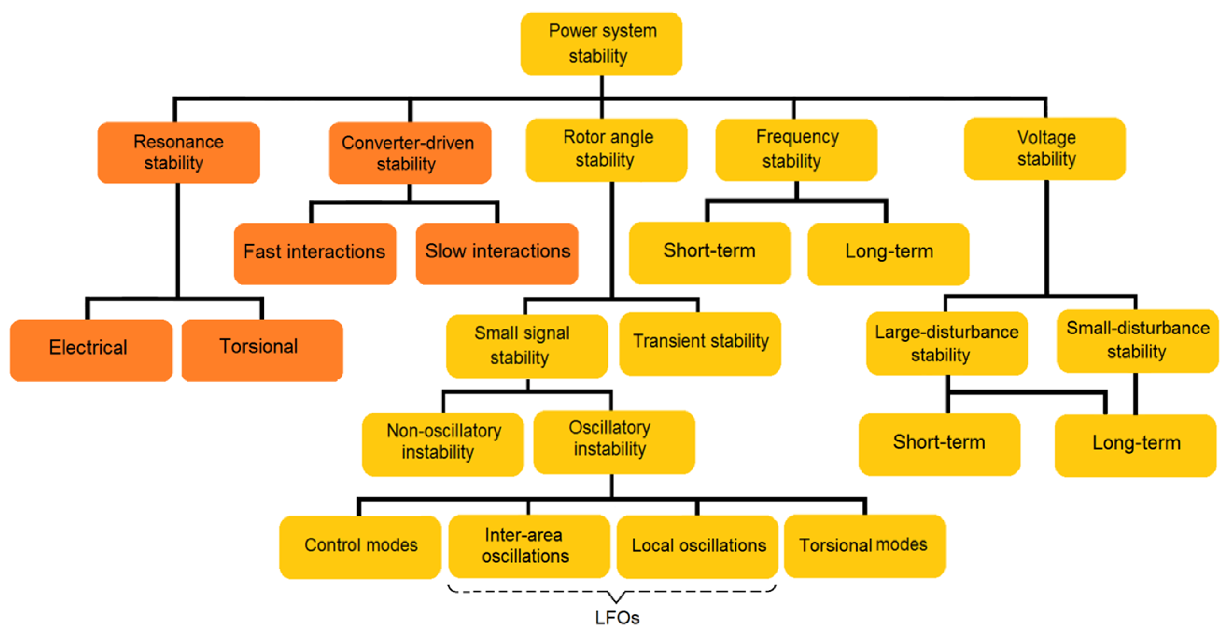
2. Concept of LFOs
- Small-signal stability;
- Transient stability.
3. Review of the FOPID Controller
3.1. Concept of Fractional-Order Calculus
- The Grunwald–Letnikov (GL) definition;
- The Riemann–Liouville (RL) definition;
- The Caputo dinition.
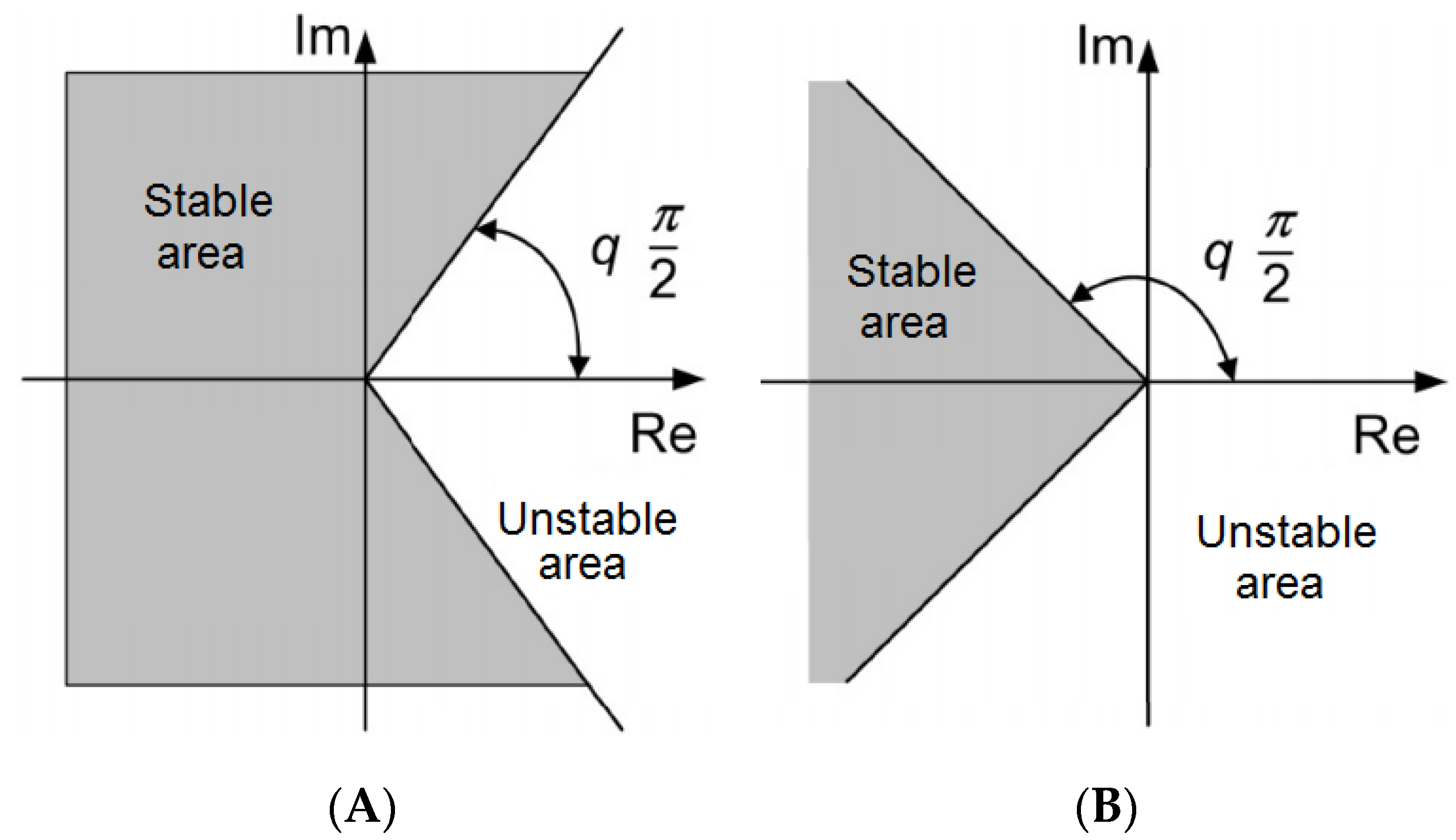
3.2. Stability of Fractional-Order System
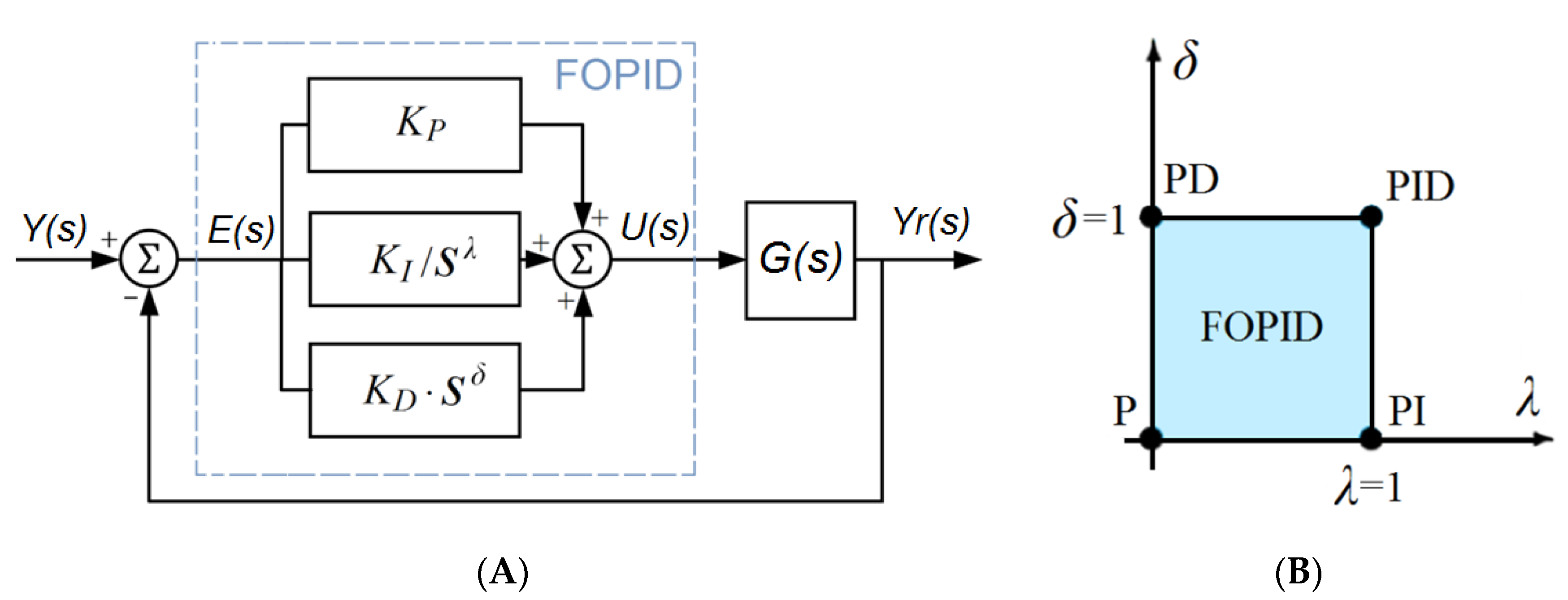
3.3. FOPID Controller
4. Tuning Methods of FOPID Controllers
- Rule-based techniques;
- Numerical techniques;
- Analytical techniques.
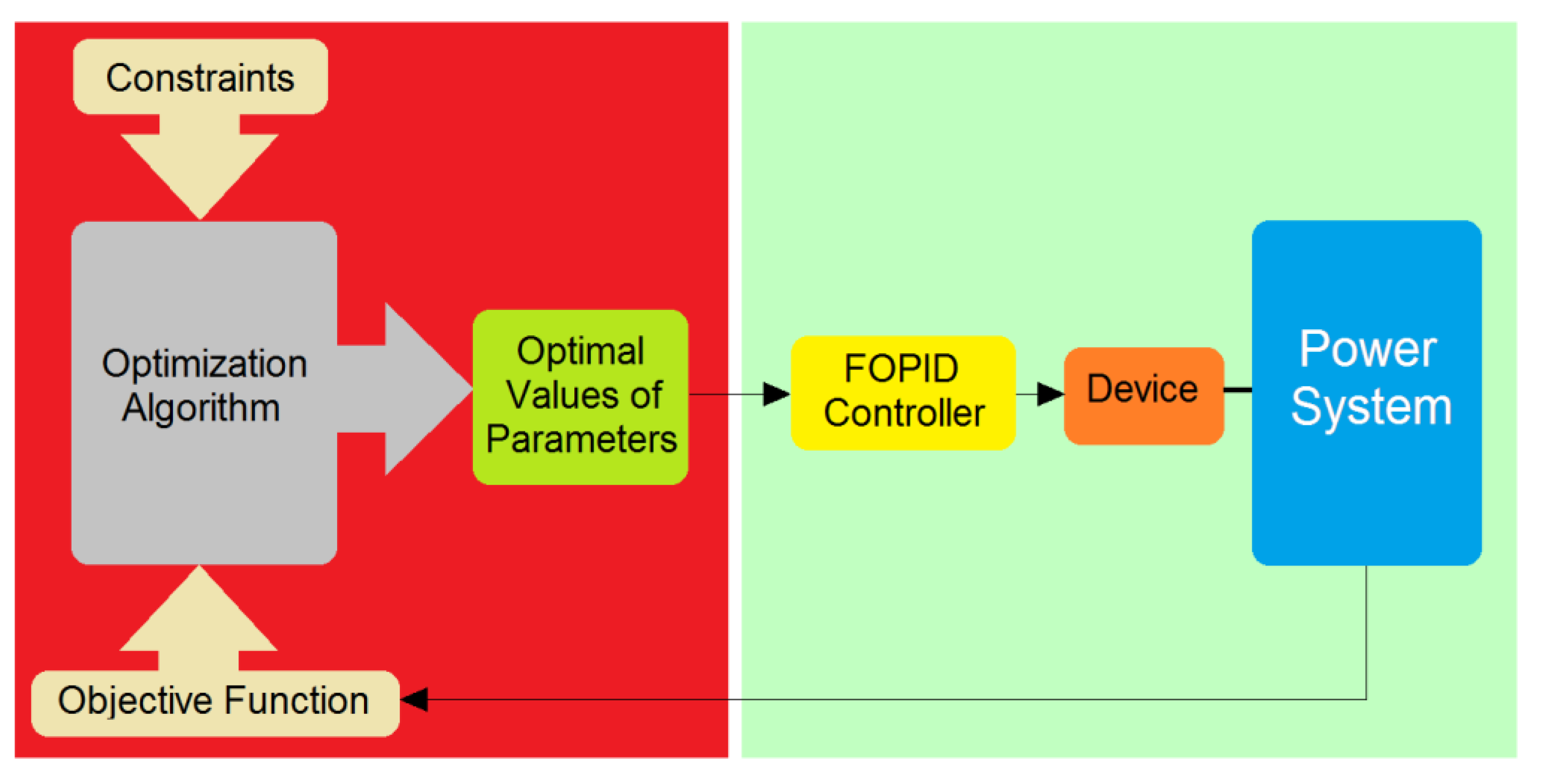
Optimization Methods Technique
5. FOPID Controller for LFO Damping in Power Systems
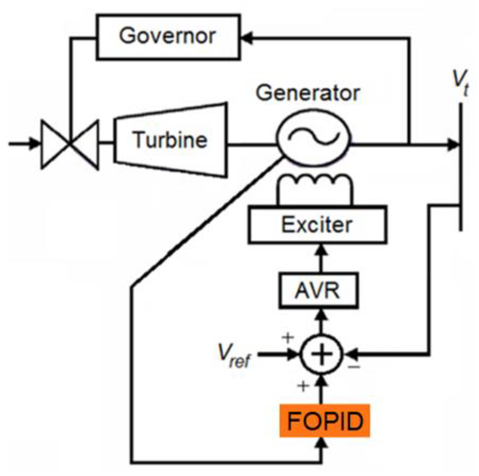
5.1. FOID-PODC of SG
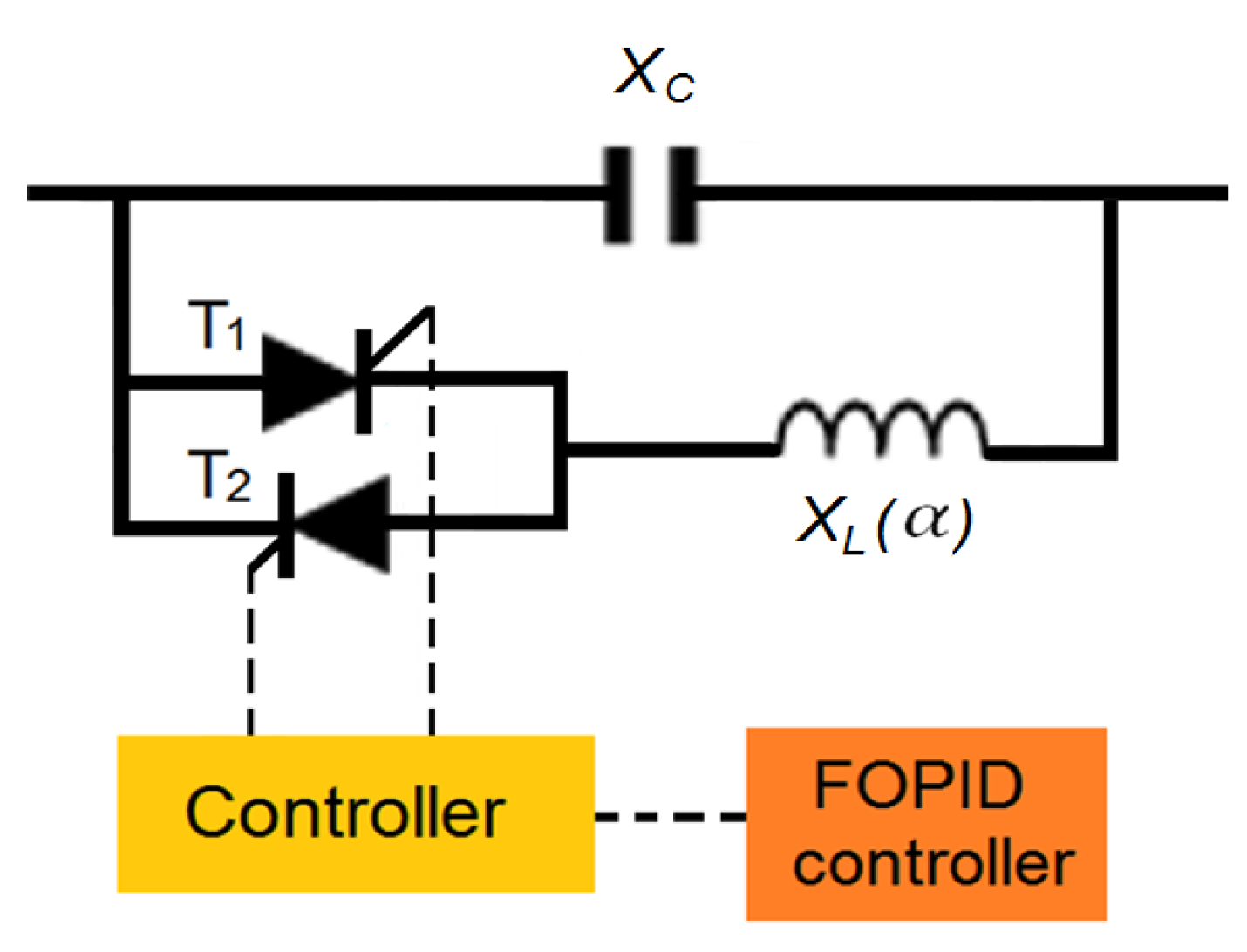
5.2. FOPID-PODC of FACTS Devices
5.3. FOPID-PODC of IBPPs
- The renewable energy generator/converter (REGC);
- The renewable energy electrical control (REEC);
- The renewable energy plant control (REPC).
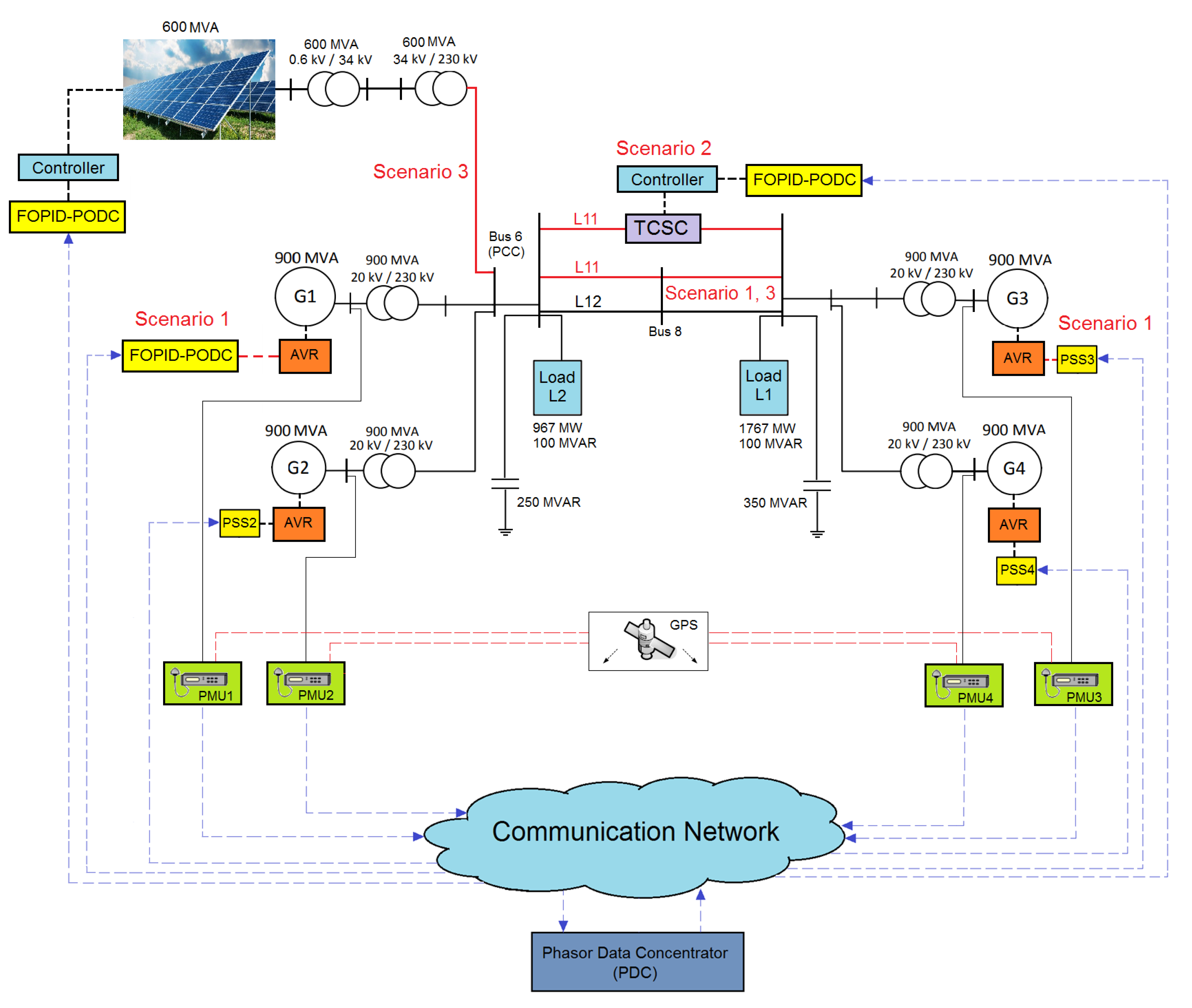
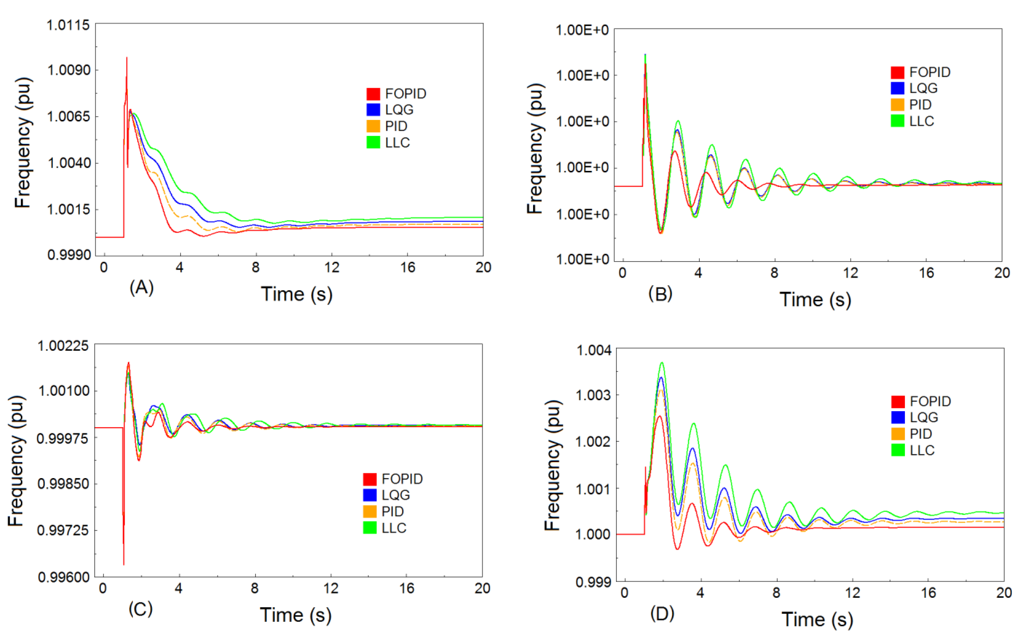
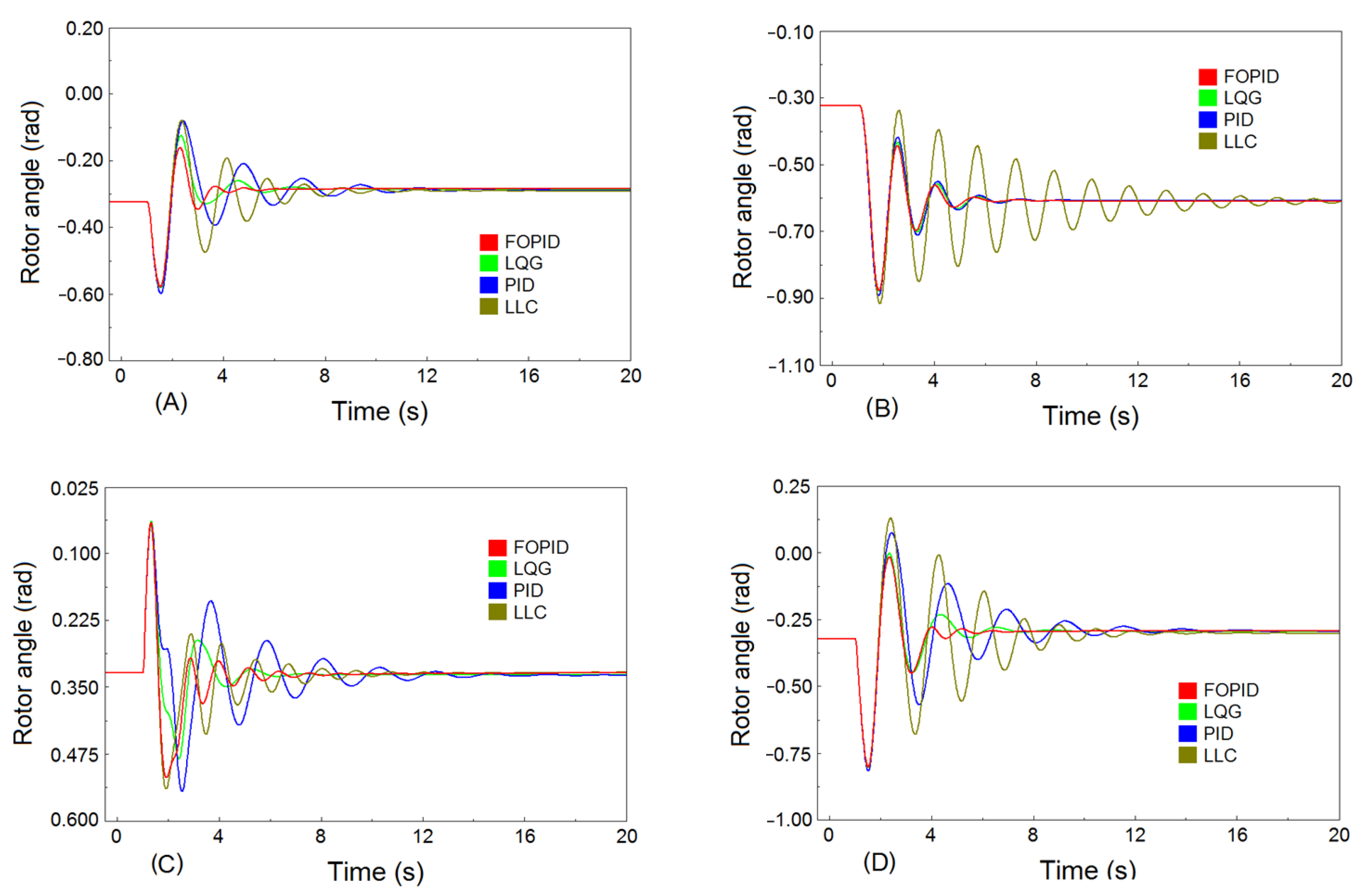
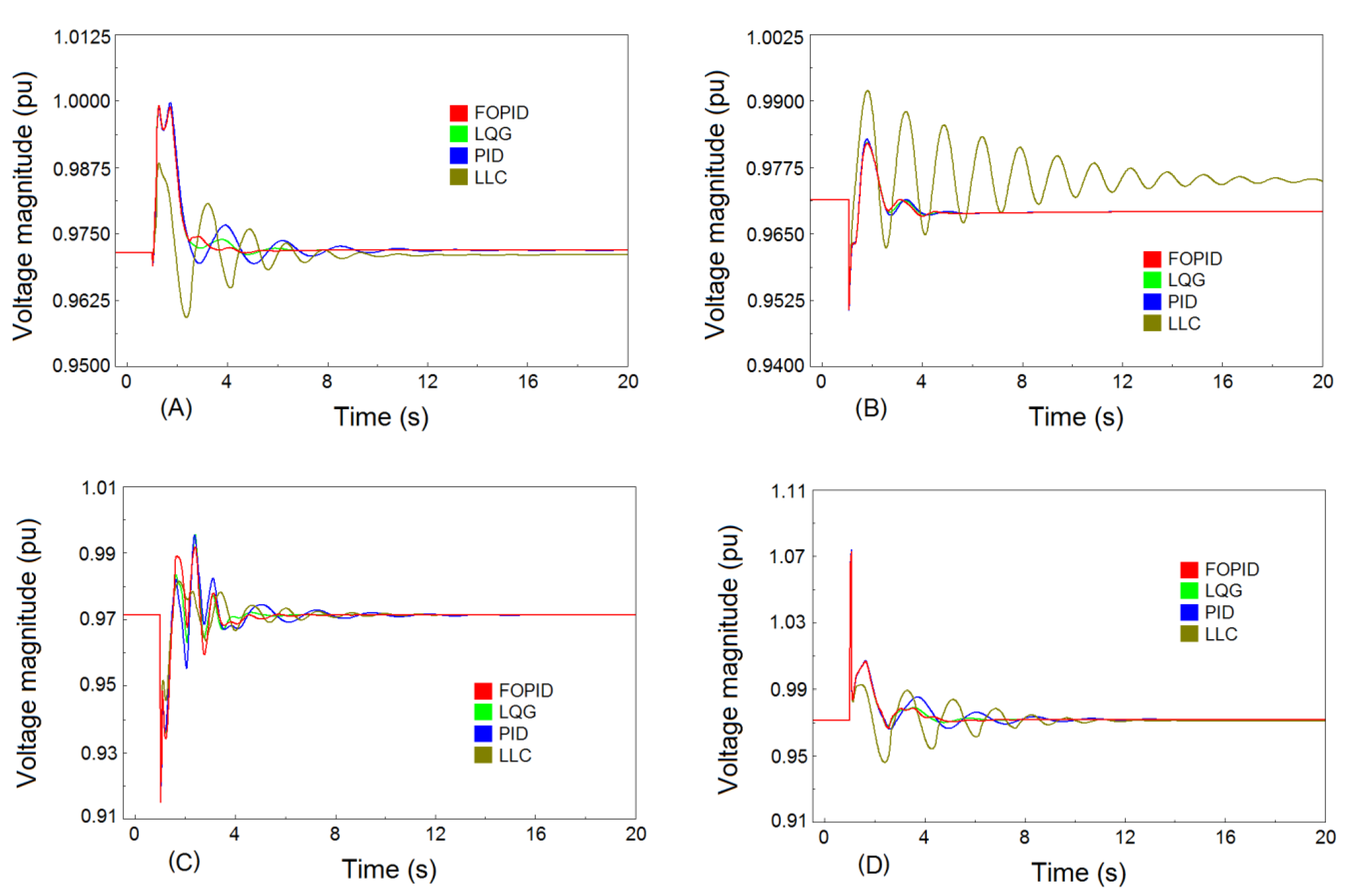
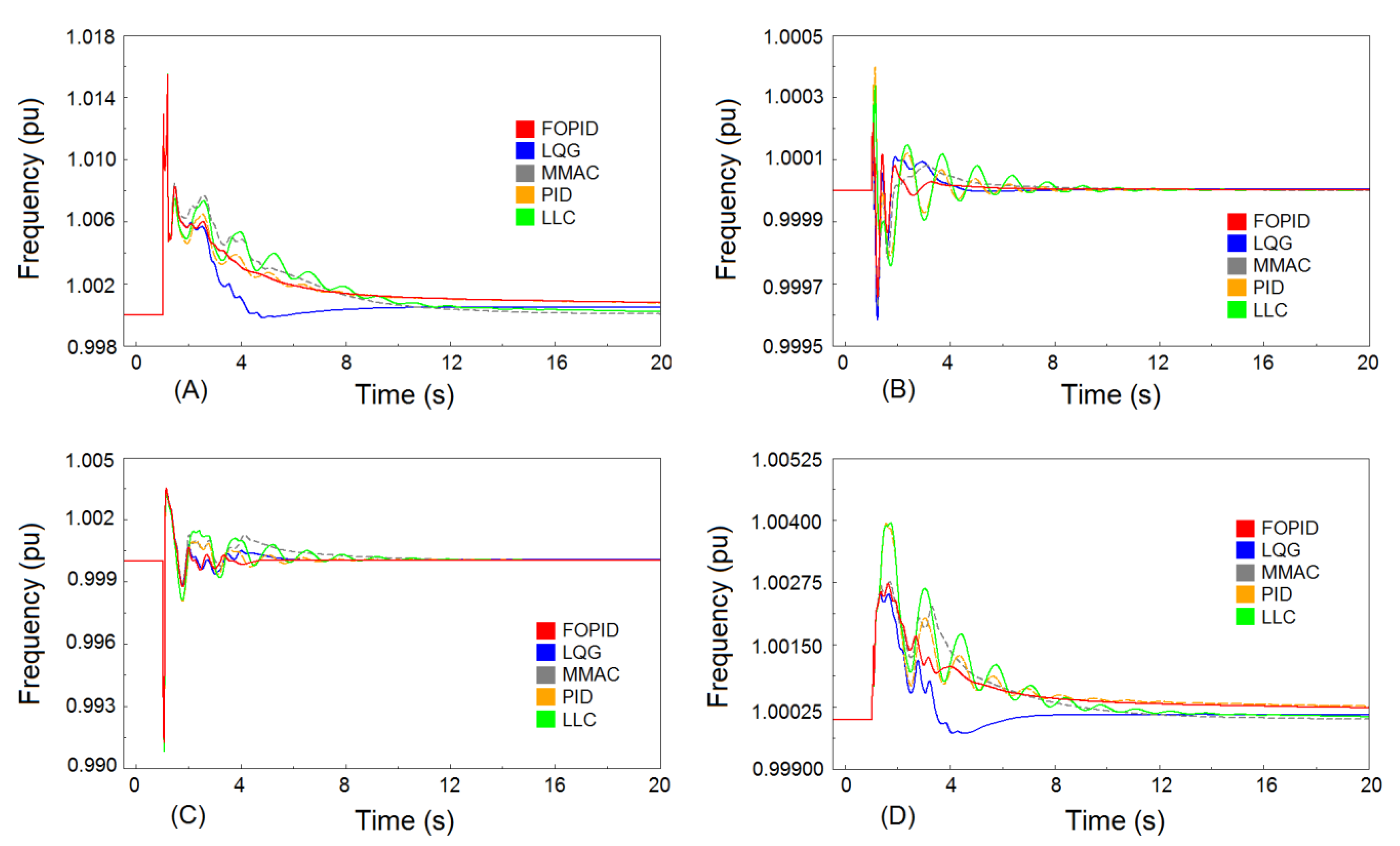
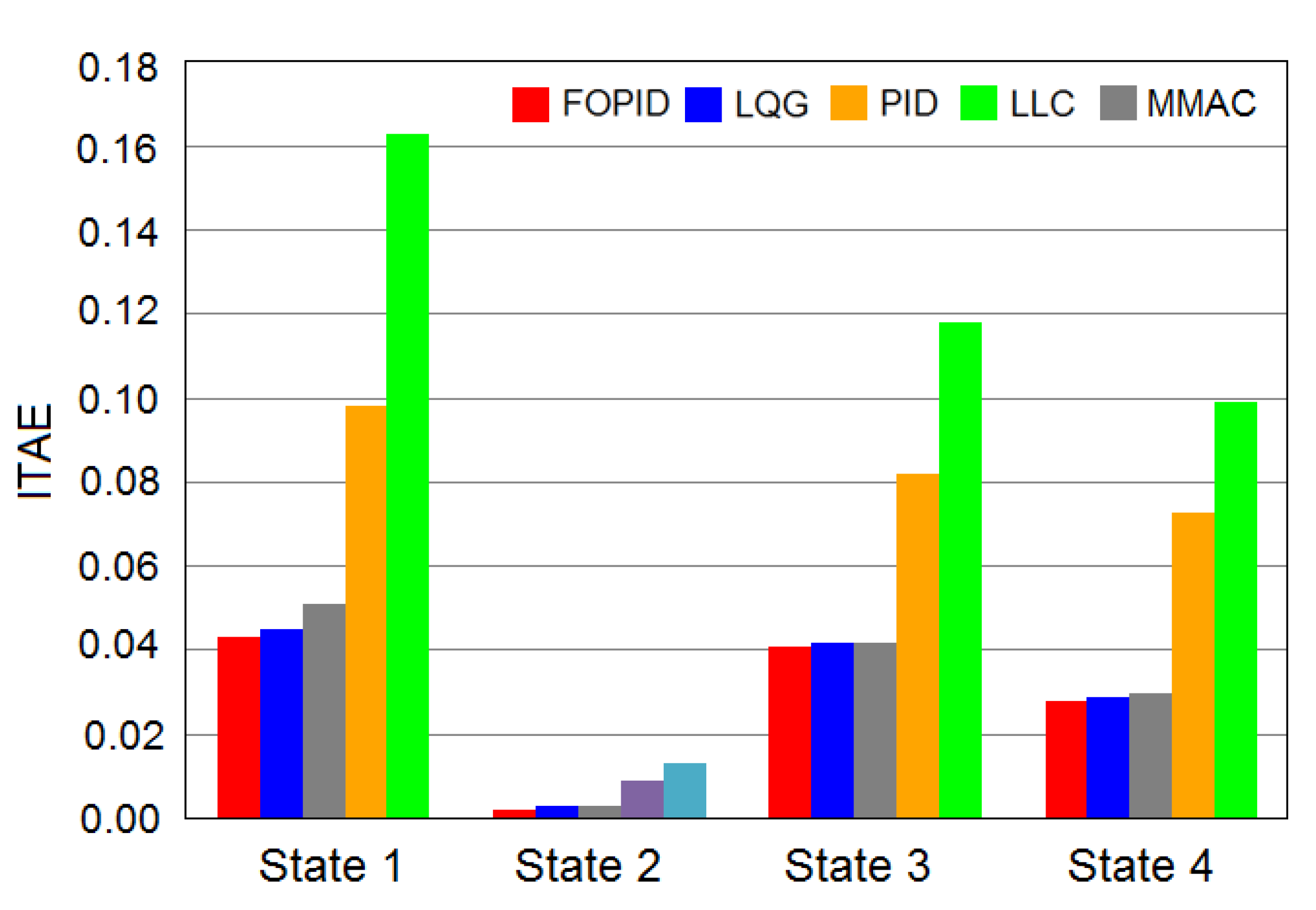
6. Performance Evaluation and Comparative Simulation
- State 1: A three-phase fault at bus 8 at t = 1 s for 170 ms.
- State 2: Disconnection of line L12 at t = 1 s for 67 ms.
- State 3: Disconnection of generator G1 at t = 1 s for 67 ms.
- State 4: Disconnection of load 2 at t = 1 s for 67 ms.
6.1. Scenario 1
6.2. Scenario 2
6.3. Scenario 3
7. Opportunities and Challenges
- Using robust controllers with a higher range of stability area in accordance with the requirements of next-generation systems;
- Damping the LFOs using new devices in power systems, such as IBPPs and FACTS devices.
8. Discussion
9. Conclusions
- Superior performance of the FOPID-PODC than conventional PODCs in terms of LFO mitigation;
- Superior performance of the FOPID-PODC than conventional PODCs in terms of robustness to some power system uncertainties.
Author Contributions
Funding
Institutional Review Board Statement
Informed Consent Statement
Data Availability Statement
Acknowledgments
Conflicts of Interest
References
- Machowski, J.; Lubosny, Z.; Bialek, J.W.; Bumby, J.R. Power System Dynamics: Stability and Control; John Wiley & Sons, Inc.: Hoboken, NJ, USA, 2020. [Google Scholar]
- Kundur, P. Power System Stability and Control; McGraw-Hill: New York, NY, USA, 1994. [Google Scholar]
- Pal, B.; Chaudhuri, B. Robust Control in Power Systems; Springer Science + Business Media, Inc.: Boston, MA, USA, 2010. [Google Scholar]
- Rogers, G. Power System Oscillations; Kluwer Academic Publishers: Boston, MA, USA, 2000. [Google Scholar]
- Shayeghi, H.; Safari, A.; Shayanfar, H. PSS and TCSC damping controller coordinated design using PSO in multi-machine power system. Energy Convers. Manag. 2010, 51, 2930–2937. [Google Scholar] [CrossRef]
- Abido, M.A.; Abdel-Magid, Y.L. Coordinated design of a PSS and an SVC-based controller to enhance power system stability. Int. J. Electr. Power Energy Syst. 2003, 25, 695–704. [Google Scholar] [CrossRef]
- Yao, W.; Jiang, L.; Wen, J.; Wu, Q.H.; Cheng, S. Wide-area damping controller of FACTS devices for inter-area oscillations considering communication time delays. IEEE Trans. Power Syst. 2013, 29, 318–329. [Google Scholar] [CrossRef] [Green Version]
- Majumder, R.; Pal, B.C.; Dufour, C.; Korba, P. Design and real-time implementation of robust FACTS controller for damping inter-area oscillation. IEEE Trans. Power Syst. 2006, 21, 809–816. [Google Scholar] [CrossRef] [Green Version]
- Hasanvand, H.; Arvan, M.R.; Mozafari, B.; Amraee, T. Coordinated design of PSS and TCSC to mitigate interarea oscillations. Int. J. Electr. Power Energy Syst. 2016, 78, 194–206. [Google Scholar] [CrossRef]
- Salgotra, A.; Pan, S. A frequency domain model-based design of PSS and TCSC controller for damping the small signal oscillations in the power system. Int. Trans. Electr. Energy Syst. 2019, 29, e2742. [Google Scholar] [CrossRef]
- Shah, R.; Mithulananthan, N.; Lee, K.Y. Large-scale PV plant with a robust controller considering power oscillation damping. IEEE Trans. Energy Convers. 2012, 28, 106–116. [Google Scholar] [CrossRef]
- Domínguez-García, J.L.; Gomis-Bellmunt, O.; Bianchi, F.D.; Sumper, A. Power oscillation damping supported by wind power: A review. Renew. Sustain. Energy Rev. 2012, 16, 4994–5006. [Google Scholar] [CrossRef]
- Zhou, L.; Yu, X.; Li, B.; Zheng, C.; Liu, J.; Liu, Q.; Guo, K. Damping inter-area oscillations with large-scale PV plant by modified multiple-model adaptive control strategy. IEEE Trans. Sustain. Energy 2017, 8, 1629–1636. [Google Scholar] [CrossRef]
- Singh, M.; Allen, A.J.; Muljadi, E.; Gevorgian, V.; Zhang, Y.; Santoso, S. Interarea oscillation damping controls for wind power plants. IEEE Trans. Sustain. Energy 2014, 6, 967–975. [Google Scholar] [CrossRef]
- Varma, R.K.; Akbari, M. Simultaneous Fast Frequency Control and Power Oscillation Damping by Utilizing PV Solar System as PV-STATCOM. IEEE Trans. Sustain. Energy 2019, 11, 415–425. [Google Scholar] [CrossRef]
- Gurung, S.; Jurado, F.; Naetiladdanon, S.; Sangswang, A. Optimized tuning of power oscillation damping controllers using probabilistic approach to enhance small-signal stability considering stochastic time delay. Electr. Eng. 2019, 101, 969–982. [Google Scholar] [CrossRef]
- Varma, R.K.; Maleki, H. PV solar system control as STATCOM (PV-STATCOM) for power oscillation damping. IEEE Trans. Sustain. Energy 2018, 10, 1793–1803. [Google Scholar] [CrossRef]
- Saadatmand, M.; Mozafari, B.; Gharehpetian, G.B.; Soleymani, S. Optimal PID controller of large-scale PV farms for power systems LFO damping. Int. Trans. Electr. Energy Syst. 2020, 30, e12372. [Google Scholar] [CrossRef]
- Monje, C.A.; Chen, Y.; Vinagre, B.M.; Xue, D.; Feliu-Batlle, V. Fractional-Order Systems and Controls: Fundamentals and Applications; Springer: London, UK, 2010. [Google Scholar]
- Shah, P.; Agashe, S. Review of fractional PID controller. Mechatronics 2016, 38, 29–41. [Google Scholar] [CrossRef]
- Podlubny, I. Fractional-order systems and -controllers. IEEE Trans. Autom. Control 1999, 44, 208–214. [Google Scholar] [CrossRef]
- Chathoth, I.; Ramdas, S.K.; Krishnan, S.T. Fractional-order proportional-integral-derivative-based automatic generation control in deregulated power systems. Electr. Power Compon. Syst. 2015, 43, 1931–1945. [Google Scholar] [CrossRef]
- Yohanandhan, R.V.; Srinivasan, L. Decentralised wide-area fractional order damping controller for a large-scale power system. IET Gener. Transm. Distrib. 2016, 10, 1164–1178. [Google Scholar] [CrossRef]
- Ayres Junior, F.A.C.; Costa Junior, C.T.; de Medeiros, R.L.P.; Barra Junior, W.; das Neves, C.C.; Lenzi, M.K.; Veroneze, C.D.M. A Fractional Order Power System Stabilizer Applied on a Small-Scale Generation System. Energies 2018, 11, 2052. [Google Scholar] [CrossRef] [Green Version]
- Tzounas, G.; Dassios, I.; Murad, M.A.; Milano, F. Theory and Implementation of Fractional Order Controllers for Power System Applications. IEEE Trans. Power Syst. 2020, 35, 4622–4631. [Google Scholar] [CrossRef]
- Taher, S.A.; Fini, M.H.; Aliabadi, S.F. Fractional order PID controller design for LFC in electric power systems using imperialist competitive algorithm. Ain Shams Eng. J. 2014, 5, 121–135. [Google Scholar] [CrossRef] [Green Version]
- Zamani, A.; Barakati, S.M.; Yousofi-Darmian, S. Design of a fractional order PID controller using GBMO algorithm for load–frequency control with governor saturation consideration. ISA Trans. 2016, 64, 56–66. [Google Scholar] [CrossRef]
- Saxena, S. Load frequency control strategy via fractional-order controller and reduced-order modeling. Int. J. Electr. Power Energy Syst. 2019, 104, 603–614. [Google Scholar] [CrossRef]
- Mohamed, E.A.; Ahmed, E.M.; Elmelegi, A.; Aly, M.; Elbaksawi, O.; Mohamed, A.A. An Optimized Hybrid Fractional Order Controller for Frequency Regulation in Multi-Area Power Systems. IEEE Access 2020, 8, 213899–213915. [Google Scholar] [CrossRef]
- Morsali, J.; Zare, K.; Hagh, M.T. A novel dynamic model and control approach for SSSC to contribute effectively in AGC of a deregulated power system. Int. J. Electr. Power Energy Syst. 2018, 95, 239–253. [Google Scholar] [CrossRef]
- Pan, I.; Das, S. Fractional order AGC for distributed energy resources using robust optimization. IEEE Trans. Smart Grid 2015, 7, 2175–2186. [Google Scholar] [CrossRef] [Green Version]
- Gorripotu, T.S.; Samalla, H.; Rao, C.J.; Azar, A.T.; Pelusi, D. TLBO algorithm optimized fractional-order PID controller for AGC of interconnected power system. In Soft Computing in Data Analytics, Proceedings of the International Conference on SCDA 2018, Srikakulam, India, 10–11 March 2018. [Google Scholar]
- Kumar, N.; Tyagi, B.; Kumar, V. Application of fractional order PID controller for AGC under deregulated environment. Int. J. Autom. Comput. 2018, 15, 84–93. [Google Scholar] [CrossRef]
- Tasnin, W.; Saikia, L.C. Deregulated AGC of multi-area system incorporating dish-Stirling solar thermal and geothermal power plants using fractional order cascade controller. Int. J. Electr. Power Energy Syst. 2018, 101, 60–74. [Google Scholar] [CrossRef]
- Mishra, A.K.; Das, S.R.; Ray, P.K.; Mallick, R.K.; Mohanty, A.; Mishra, D.K. PSO-GWO Optimized Fractional Order PID Based Hybrid Shunt Active Power Filter for Power Quality Improvements. IEEE Access 2020, 8, 74497–74512. [Google Scholar] [CrossRef]
- Zamani, M.; Karimi-Ghartemani, M.; Sadati, N.; Parniani, M. Design of a fractional order PID controller for an AVR using particle swarm optimization. Control Eng. Pract. 2009, 17, 380–1387. [Google Scholar] [CrossRef]
- Pan, I.; Das, S. Chaotic multi-objective optimization based design of fractional order PIλDµ controller in AVR system. Int. J. Electr. Power Energy Syst. 2012, 43, 393–407. [Google Scholar] [CrossRef] [Green Version]
- Pan, I.; Das, S. Frequency domain design of fractional order PID controller for AVR system using chaotic multi-objective optimization. Int. J. Electr. Power Energy Syst. 2013, 51, 106–118. [Google Scholar] [CrossRef] [Green Version]
- Chiranjeevi, S.B. Implementation of fractional order PID controller for an AVR system using GA and ACO optimization techniques. IFAC-PapersOnLine 2016, 49, 456–461. [Google Scholar]
- Chaib, L.; Choucha, A.; Arif, S. Optimal design and tuning of novel fractional order PID power system stabilizer using a new metaheuristic Bat algorithm. Ain Shams Eng. J. 2017, 8, 113–125. [Google Scholar] [CrossRef] [Green Version]
- Sikander, A.; Thakur, P.; Bansal, R.C.; Rajasekar, S. A novel technique to design cuckoo search based FOPID controller for AVR in power systems. Comput. Elec. Eng. 2018, 70, 261–274. [Google Scholar] [CrossRef]
- Bhookya, J.; Jatoth, R.K. Optimal FOPID/PID controller parameters tuning for the AVR system based on sine–cosine-algorithm. Evol. Intell. 2019, 12, 725–733. [Google Scholar] [CrossRef]
- Ray, P.K.; Paital, S.R.; Mohanty, A.; Foo, Y.E.; Krishnan, A.; Gooi, H.B.; Amaratunga, G.A. A hybrid firefly-swarm optimized fractional order interval type-2 fuzzy PID-PSS for transient stability improvement. IEEE Trans. Ind. App. 2019, 55, 6486–6498. [Google Scholar] [CrossRef]
- Micev, M.; Ćalasan, M.; Oliva, D. Fractional order PID controller design for an AVR system using Chaotic Yellow Saddle Goatfish Algorithm. Mathematics 2020, 8, 1182. [Google Scholar] [CrossRef]
- Morsali, J.; Zare, K.; Hagh, M.T. Applying fractional order PID to design TCSC-based damping controller in coordination with automatic generation control of interconnected multi-source power system. Eng. Sci. Technol. Int. J. 2017, 20, 1–7. [Google Scholar] [CrossRef] [Green Version]
- Paital, S.R.; Ray, P.K.; Mohanty, A. Dolphin Echolocation and Fractional Order PID-Based STATCOM for Transient Stability Enhancement. In Recent Findings in Intelligent Computing Techniques, Proceedings of the 5th ICACNI, Goa, India, 1–3 June 2017; Springer: Singapore, 2018. [Google Scholar]
- Saadatmand, M.; Mozafari, B.; Gharehpetian, G.B.; Soleymani, S. Optimal fractional-order PID controller of inverter-based power plants for power systems LFO damping. Turk. J. Electr. Eng. Comput. Sci. 2020, 28, 485–499. [Google Scholar] [CrossRef]
- Saadatmand, M.; Mozafari, B.; Gharehpetian, G.B.; Soleymani, S. Optimal Coordinated Tuning of Power System Stabilizers and Wide-area Measurement-based Fractional-order PID Controller of Large-scale PV Farms for LFO Damping in Smart Grids. Int. Trans. Electr. Energy Syst. 2021, 31, e12612. [Google Scholar] [CrossRef]
- Saadatmand, M.; Gharehpetian, G.B.; Siano, P.; Alhelou, H.H. PMU-based FOPID Controller of Large-scale Wind-PV Farms for LFO Damping in Smart Grid. IEEE Access 2021, 9, 94953–94969. [Google Scholar] [CrossRef]
- Kundur, P.; Paserba, J.; Ajjarapu, V.; Andersson, G.; Bose, A.; Canizares, C.; Hatziargyriou, N.; Hill, D.; Stankovic, A.; Taylor, C.; et al. Definition and classification of power system stability IEEE/CIGRE joint task force on stability terms and definitions. IEEE Trans. Power Syst. 2004, 19, 1387–1401. [Google Scholar]
- Hatziargyriou, N.; Milanovic, J.V.; Rahmann, C.; Ajjarapu, V.; Canizares, C.; Erlich, I.; Hill, D.; Hiskens, I.; Kamwa, I.; Pal, B.; et al. Definition and classification of power system stability revisited & extended. IEEE Trans. Power Syst. 2020, 36, 3271–3281. [Google Scholar]
- Hatziargyriou, N.; Milanovic, J.V.; Rahmann, C.; Ajjarapu, V.; Canizares, C.; Erlich, I.; Hill, D.; Hiskens, I.; Kamwa, I.; Pal, B.; et al. Stability Definitions and Characterization of Dynamic Behavior in Systems with High Penetration of Power Electronic Interfaced Technologies; Technical Report PESTR77; IEEE Power and Energy Society: Piscataway, NJ, USA, 2020. [Google Scholar]
- Miller, K.S.; Ross, B. An Introduction to the Fractional Calculus and Fractional Differential Equations; John Wiley: New York, NY, USA, 1993. [Google Scholar]
- Singh, H.; Kumar, D.; Baleanu, D. Methods of Mathematical Modelling: Fractional Differential Equations; CRC Press, Taylor & Francis Group: Boca Raton, FL, USA, 2020. [Google Scholar]
- Oldham, K.B.; Spanier, J. The Fractional Calculus; Academic Press: New York, NY, USA, 1974. [Google Scholar]
- Lanusse, P.; Malti, R.; Melchior, P. CRONE control system design toolbox for the control engineering community: Tutorial and case study. Philos. Trans. R. Soc. A Math. Phys. Eng. Sci. 2013, 371, 20120149. [Google Scholar] [CrossRef] [Green Version]
- Dastjerdi, A.A.; Saikumar, N.; HosseinNia, S.H. Tuning guidelines for fractional order PID controllers: Rules of thumb. Mechatronics 2018, 56, 26–36. [Google Scholar] [CrossRef]
- Sánchez, H.S.; Padula, F.; Visioli, A.; Vilanova, R. Tuning rules for robust FOPID controllers based on multi-objective optimization with FOPDT models. ISA Trans. 2017, 66, 344–361. [Google Scholar] [CrossRef] [PubMed] [Green Version]
- Yousaf, S.; Mughees, A.; Khan, M.G.; Amin, A.A.; Adnan, M.A. A Comparative Analysis of Various Controller Techniques for Optimal Control of Smart Nano-Grid Using GA and PSO Algorithms. IEEE Access 2020, 8, 205696–205711. [Google Scholar] [CrossRef]
- Daraz, A.; Malik, S.A.; Mokhlis, H.; Haq, I.U.; Zafar, F.; Mansor, N. N. Improved-Fitness Dependent Optimizer Based FOI-PD Controller for Automatic Generation Control of Multi-Source Interconnected Power System in Deregulated Environment. IEEE Access 2020, 8, 197757–197775. [Google Scholar] [CrossRef]
- Wang, H.; Wang, H.; Zeng, G.; Dai, Y.; Bi, D.; Sun, J.; Xie, X. Design of a fractional order frequency PID controller for an islanded microgrid: A multi-objective extremal optimization method. Energies 2017, 10, 1502. [Google Scholar] [CrossRef] [Green Version]
- Nie, Y.; Zhang, Y.; Zhao, Y.; Fang, B.; Zhang, L. Wide-area optimal damping control for power systems based on the ITAE criterion. Int. J. Electr. Power Energy Syst. 2019, 106, 192–200. [Google Scholar] [CrossRef]
- Khezri, R.; Oshnoei, A.; Tarafdar Hagh, M.; Muyeen, S.M. Coordination of heat pumps, electric vehicles and AGC for efficient LFC in a smart hybrid power system via SCA-based optimized FOPID controllers. Energies 2018, 11, 420. [Google Scholar] [CrossRef] [Green Version]
- Pan, I.; Das, S. Fractional-order load-frequency control of interconnected power systems using chaotic multi-objective optimization. Appl. Soft Comput. 2015, 29, 328–344. [Google Scholar] [CrossRef] [Green Version]
- Irudayaraj, A.X.R.; Wahab, N.I.; Umamaheswari, M.G.; Radzi, M.A.; Sulaiman, N.B.; Veerasamy, V.; Prasanna, S.C.; Ramachandran, R. A Matignon’s Theorem Based Stability Analysis of Hybrid Power System for Automatic Load Frequency Control Using Atom Search Optimized FOPID Controller. IEEE Access 2020, 8, 168751–168772. [Google Scholar] [CrossRef]
- Hekimoğlu, B. Optimal Tuning of Fractional Order PID Controller for DC Motor Speed Control via Chaotic Atom Search Optimization Algorithm. IEEE Access 2019, 7, 38100–38114. [Google Scholar] [CrossRef]
- Arya, Y.; Kumar, N. BFOA-scaled fractional order fuzzy PID controller applied to AGC of multi-area multi-source electric power generating systems. Swarm Evol. Comput. 2017, 32, 202–218. [Google Scholar] [CrossRef]
- Morsali, J.; Zare, K.; Hagh, M.T. Modified group search optimisation-based comparative performance evaluation of thyristor controlled series capacitor-based fractional order damping controllers to improve load frequency control performance in restructured environment. IET Gener. Transm. Distrib. 2017, 11, 4654–4669. [Google Scholar] [CrossRef]
- Ismayil, C.; Kumar, R.S.; Sindhu, T.K. Optimal fractional order PID controller for automatic generation control of two-area power systems. Int. Trans. Electr. Energy Syst. 2015, 25, 3329–3348. [Google Scholar] [CrossRef]
- Zhao, P.; Malik, O.P. Design of an adaptive PSS based on recurrent adaptive control theory. IEEE Trans. Energy Convers. 2009, 24, 884–892. [Google Scholar] [CrossRef]
- Zhang, S.; Luo, F.L. An improved simple adaptive control applied to power system stabilizer. IEEE Trans. Power Electron. 2009, 24, 369–375. [Google Scholar] [CrossRef]
- Milla, F.; Duarte-Mermoud, M.A. Predictive optimized adaptive PSS in a single machine infinite bus. ISA Trans. 2016, 63, 315–327. [Google Scholar] [CrossRef]
- Barreiros, J.A.; Ferreira, A.M.; Tavares-da-Costa, C., Jr.; Barra, W., Jr.; Lopes, J.A. A neural power system stabilizer trained using local linear controllers in a gain-scheduling scheme. Int. J. Electr. Power Energy Syst. 2005, 27, 473–479. [Google Scholar] [CrossRef]
- Hasanovic, A.M.; Feliachi, A.; Bhatt, N.B.; DeGroff, A.G. Practical robust PSS design through identification of low-order transfer functions. IEEE Trans. Power Syst. 2004, 19, 1492–1500. [Google Scholar] [CrossRef]
- Bandal, V.; Bandyopadhyay, B. Robust decentralised output feedback sliding mode control technique-based power system stabiliser (PSS) for multimachine power system. IET Control Theory Appl. 2007, 1, 1512–1522. [Google Scholar] [CrossRef]
- Bakhshi, M.; Holakooie, M.H.; Rabiee, A. Fuzzy based damping controller for TCSC using local measurements to enhance transient stability of power systems. Int. J. Electr. Power Energy Syst. 2017, 85, 12–21. [Google Scholar] [CrossRef]
- Kalyan, C.N.; Rao, G.S. Coordinated SMES and TCSC Damping Controller for Load Frequency Control of Multi Area Power System with Diverse Sources. Int. J. Electr. Eng. Inform. 2020, 12, 747–769. [Google Scholar]
- Luburić, Z.; Pandžić, H.; Carrión, M. Transmission Expansion Planning Model Considering Battery Energy Storage, TCSC and Lines Using AC OPF. IEEE Access 2020, 8, 203429–203439. [Google Scholar] [CrossRef]
- Ordóñez, C.A.; Gómez-Expósito, A.; Maza-Ortega, J.M. Series Compensation of Transmission Systems: A Literature Survey. Energies 2021, 14, 1717. [Google Scholar] [CrossRef]
- Eftekharnejad, S.; Vittal, V.; Heydt, G.T.; Keel, B.; Loehr, J. Impact of increased penetration of photovoltaic generation on power systems. IEEE Trans. Power Syst. 2012, 28, 893–901. [Google Scholar] [CrossRef]
- Quintero, J.; Vittal, V.; Heydt, G.T.; Zhang, H. The impact of increased penetration of converter control-based generators on power system modes of oscillation. IEEE Trans. Power Syst. 2014, 29, 2248–2256. [Google Scholar] [CrossRef]
- Pourbeik, P.; Sanchez-Gasca, J.J.; Senthil, J.; Weber, J.D.; Zadehkhost, P.S.; Kazachkov, Y.; Tacke, S.; Wen, J.; Ellis, A. Generic dynamic models for modeling wind power plants and other renewable technologies in large-scale power system studies. IEEE Trans. Energy Convers. 2016, 32, 1108–1116. [Google Scholar] [CrossRef]
- Canizares, C.; Fernandes, T.; Geraldi, E.; Gerin-Lajoie, L.; Gibbard, M.; Hiskens, I.; Kersulis, J.; Kuiava, R.; Lima, L.; DeMarco, F.; et al. Benchmark Models for the Analysis and Control of Small-Signal Oscillatory Dynamics in Power Systems. IEEE Trans. Power Syst. 2017, 32, 715–722. [Google Scholar] [CrossRef]
- Cai, D. Wide Area Monitoring, Protection and Control in the Future Great Britain Power System. Ph.D. Thesis, University of Manchester, Manchester, UK, 2012. [Google Scholar]
- Kerahroudi, S.K.; Alamuti, M.M.; Li, F.; Taylor, G.A.; Bradley, M.E. Application and Requirement of DIgSILENT PowerFactory to MATLAB/Simulink Interface. In PowerFactory Applications for Power System Analysis; Gonzalez-Longatt, F.M., Rueda, J.L., Eds.; Springer: Cham, Switzerland, 2014; pp. 297–322. [Google Scholar]
- Das, T.K.; Venayagamoorthy, G.K.; Aliyu, U.O. Bio-inspired algorithms for the design of multiple optimal power system stabilizers: SPPSO and BFA. IEEE Trans. Ind. Appl. 2008, 44, 1445–1457. [Google Scholar] [CrossRef]
- Li, C.; Deng, J.; Zhang, X.P. Coordinated design and application of robust damping controllers for shunt FACTS devices to enhance small-signal stability of large-scale power systems. CSEE J. Power Energy Syst. 2017, 25, 399–407. [Google Scholar] [CrossRef]
- Yathisha, L.; Patilkulkarni, S. LQR and LQG based optimal switching techniques for PSS and UPFC in power systems. Control Theory Technol. 2018, 16, 25–37. [Google Scholar] [CrossRef]
- Ghouraf, D.E.; Naceri, A. Robust H2-PSS design based on LQG control optimized by genetic algorithms. Autom. Control Comput. Sci. 2017, 51, 301–310. [Google Scholar] [CrossRef]
- ASV, V.L.; Manyala, R.R.; Mangipudi, S.K. Design of a robust PID-PSS for an uncertain power system with simplified stability conditions. Prot. Control Mod. Power Syst. 2020, 5, 20. [Google Scholar]
- Dudgeon, G.J.W.; Leithead, W.E.; Dysko, A.; o’Reilly, J.; McDonald, J.R. The Effective Role of AVR and PSS in Power Systems: Frequency Response Analysis. IEEE Trans. Power Syst. 2007, 22, 1986–1994. [Google Scholar] [CrossRef]
- Chatterjee, A.; Mukherjee, V.; Ghoshal, S.P. Velocity relaxed and craziness-based swarm optimized intelligent PID and PSS controlled AVR system. Int. J. Electr. Power Energy Syst. 2009, 31, 323–333. [Google Scholar] [CrossRef]
- Mukherjee, V.; Ghoshal, S.P. Comparison of intelligent fuzzy based AGC coordinated PID controlled and PSS controlled AVR system. Int. J. Electr. Power Energy Syst. 2007, 29, 679–689. [Google Scholar] [CrossRef]
- Ramos, R.A. Stability analysis of power systems considering AVR and PSS output limiters. Int. J. Electr. Power Energy Syst. 2009, 31, 153–159. [Google Scholar] [CrossRef]
- Dysko, A.; Leithead, W.E.; O’Reilly, J. Enhanced Power System Stability by Coordinated PSS Design. IEEE Trans. Power Syst. 2010, 25, 413–422. [Google Scholar] [CrossRef]
- Prasertwong, K.; Mithulananthan, N.; Thakur, D. Understanding low-frequency oscillation in power systems. Int. J. Electr. Eng. Educ. 2010, 47, 248–262. [Google Scholar]
- Liu, H.; Su, J.; Yang, Y.; Qin, Z.; Li, C. Compatible Decentralized Control of AVR and PSS for Improving Power System Stability. IEEE Syst. J. 2020, 15, 2410–2419. [Google Scholar] [CrossRef]
- Kumar, A. Ideal AVR and PSS: A theoretical study. IET Gener. Transm. Distrib. 2020, 14, 6250–6258. [Google Scholar] [CrossRef]
- Son, K.M.; Park, J.K. On the robust LQG control of TCSC for damping power system oscillations. IEEE Trans. Power Syst. 2000, 15, 1306–1312. [Google Scholar] [CrossRef]
- Ferreira, A.M.; Barreiros, J.A.; Barra, J.R.W.; Brito-de-Souza, J.R. A robust adaptive LQG/LTR TCSC controller applied to damp power system oscillations. Electr. Power Syst. Res. 2007, 77, 956–964. [Google Scholar] [CrossRef]
- Zolotas, A.C.; Chaudhuri, B.; Jaimoukha, I.M.; Korba, P. A Study on LQG/LTR Control for Damping Inter-Area Oscillations in Power Systems. IEEE Trans. Control Syst. Technol. 2007, 15, 151–160. [Google Scholar] [CrossRef]
- Panda, S. Differential evolutionary algorithm for TCSC-based controller design. Simul. Model. Pract. Theory 2009, 17, 1618–1634. [Google Scholar] [CrossRef]
- Fan, L.; Feliachi, A.; Schoder, K. Selection and design of a TCSC control signal in damping power system inter-area oscillations for multiple operating conditions. Electr. Power Syst. Res. 2002, 62, 127–137. [Google Scholar] [CrossRef]
- Abdel-Magid, Y.L.; Abido, M.A. Robust coordinated design of excitation and TCSC-based stabilizers using genetic algorithms. Electr. Power Syst. Res. 2004, 69, 129–141. [Google Scholar] [CrossRef]
- WECC. PV Plant Power Flow Modeling Guide; Western Electricity Coordinating Council: Salt Lake City, UT, USA, 2010. [Google Scholar]
- WECC. Renewable Energy Modeling Task Force: WECC PV Power Plant Dynamic Modeling Guide; Western Electricity Coordinating Council: Salt Lake City, UT, USA, 2014. [Google Scholar]
- Pourbeik, P. Model User Guide for Generic Renewable Energy System Models; Electric Power Research Institute: Palo Alto, CA, USA, 2015. [Google Scholar]
- Kamwa, I.; Grondin, R.; Trudel, G. IEEE PSS2B versus PSS4B: The limits of performance of modern power system stabilizers. IEEE Trans. Power Syst. 2005, 20, 903–915. [Google Scholar] [CrossRef]
- Khodabakhshian, A.; Hemmati, R.; Moazzami, M.M. Multi-band power system stabilizer design by using CPCE algorithm for multi-machine power system. Electr. Power Syst. Res. 2013, 101, 36–48. [Google Scholar] [CrossRef]
- Rimorov, D.; Kamwa, I.; Joós, G. Model-based tuning approach for multi-band power system stabilisers PSS4B using an improved modal performance index. IET Gener. Transm. Distrib. 2015, 9, 2135–2143. [Google Scholar] [CrossRef]
- Abdulkhader, H.K.; Jacob, J.; Mathew, A.T. Fractional-order lead-lag compensator-based multi-band power system stabiliser design using a hybrid dynamic GA-PSO algorithm. IET Gener. Transm. Distrib. 2018, 12, 3248–3260. [Google Scholar] [CrossRef]
- Warrier, P.; Shah, P. Fractional Order Control of Power Electronic Converters in Industrial Drives and Renewable Energy Systems: A Review. IEEE Access 2021, 9, 58982–59009. [Google Scholar] [CrossRef]
- Tepljakov, A.; Alagoz, B.B.; Yeroglu, C.; Gonzalez, E.A.; Hosseinnia, S.H.; Petlenkov, E.; Ates, A.; Cech, M. Towards Industrialization of FOPID Controllers: A Survey on Milestones of Fractional-Order Control and Pathways for Future Developments. IEEE Access 2021, 9, 21016–21042. [Google Scholar] [CrossRef]


| Reference | Optimization Algorithm | Power System Application |
|---|---|---|
| [32] | Teaching–learning-based optimization (TLBO) | AGC |
| [36] | Particle swarm optimization (PSO) | PODC |
| [37,38] | Chaotic non-dominated sorting genetic algorithm-II (chaotic NSGA-II) | PODC |
| [39] | Genetic algorithm (GA), ant colony optimization (ACO) | PODC |
| [40] | Bat algorithm (BA) | PODC |
| [41] | Cuckoo search (CS) | PODC |
| [42] | Sine–cosine algorithm (SCA) | PODC |
| [43] | Hybrid firefly algorithm-PSO (FAPSO) | PODC |
| [44] | Chaotic yellow saddle goatfish algorithm | PODC |
| [45] | Improved PSO (IPSO) | PODC |
| [46] | Dolphin echolocation optimization (DEO) | PODC |
| [47] | PSO | PODC |
| [48] | PSO, GA | PODC |
| [49] | TLBO, PSO, GA | PODC |
| [63] | SCA | AGC |
| [64] | Chaotic multi-objective optimization | LFC |
| [65] | Atom search optimization (ASO) | LFC |
| [66] | Chaotic ASO (ChASO) | Controller of DC motor |
| [67] | Bacterial foraging optimization algorithm (BFOA), hybrid firefly algorithm-pattern search (hFA-PS), grey wolf optimization (GWO), GA | AGC |
| [68] | Group search optimization (GSO) | LFC |
| [69] | GA | AGC |
| Reference | Device | Tuning Method | Comparison with Other Controllers | Time- Domain Analysis | Frequency- Domain Analysis |
|---|---|---|---|---|---|
| [36] | SG | Optimization by PSO | No | Yes | No |
| [37,38] | SG | Optimization by chaotic NSGA-II | No | Yes | No |
| [39] | SG | Optimization by ACO | Yes | Yes | No |
| [40] | SG | Optimization by BA | Yes | Yes | No |
| [41] | SG | Optimization by CS | Yes | Yes | No |
| [42] | SG | Optimization by SCA | Yes | Yes | No |
| [43] | SG | Optimization by FAPSO | No | Yes | Yes |
| [44] | SG | Optimization by chaoticyellow saddle goatfish algorithm | No | Yes | No |
| [45] | FACTS (TCSC) | Optimization by IPSO | Yes | Yes | Yes |
| [46] | FACTS (STATCOM) | Optimization by DEO | No | Yes | No |
| [47] | IBPP (LPF) | Optimization by PSO | Yes | Yes | No |
| [48] | IBPP (LPF) | Optimization by PSO | Yes | Yes | No |
| [49] | IBPP (LWPF) | Optimization by TLBO | Yes | Yes | No |
| Scenario | Application |
|---|---|
| 1 | Supplementary controller for excitation system of an SG as a PSS |
| 2 | Auxiliary controller of TCSC as a PODC |
| 3 | Supplementary controller of LPF controller as a PODC |
| Item | Description/Value |
|---|---|
| Dynamic model of SGs | Sixth-order model |
| Exciters model | IEEE-ST1A |
| PSSs model | STAB1 |
| Loads | Constant power load |
| Constant time delay of signal transmission | 100 ms [84,85] |
| Item | KP | KI | KD | λ | δ |
|---|---|---|---|---|---|
| Upper range | 100 | 100 | 100 | 1 | 1 |
| Lower range | 0 | 0 | 0 | 0 | 0 |
| Item | Value |
|---|---|
| KP | 32.752 |
| KI | 64.958 |
| KD | 82.003 |
| λ | 0.4910 |
| δ | 0.5360 |
| Parameter | Value |
|---|---|
| Time constant of TCSC (Tf) (s) | 0.05 |
| Series capacitor of TCSC (Xc) (Ohm) | 20 |
| XL-Min (minimum reactance) (Ohm) | 25 |
| XL-Max (maximum reactance) (Ohm) | 50 |
| XMin (Ohm) | 11.1 |
| XMax (Ohm) | 14.3 |
| Item | Value |
|---|---|
| KP | 86.423 |
| KI | 61.622 |
| KD | 73.355 |
| λ | 0.687 |
| δ | 0.337 |
| Item | Value |
|---|---|
| KP | 26.874 |
| KI | 32.821 |
| KD | 85.233 |
| λ | 0.266 |
| δ | 0.219 |
| Opportunity | Description |
|---|---|
| Wide range of stability area | Due to the nature of the FOPID controller, this type of controller provides a large range of stability area. |
| Robustness | Due to the natural properties of the FOPID controller, which is due to the fractional orders of derivative and integral operators, this type of controller has a high robustness against system uncertainties. |
| Flexibility in design | It seems that the most important opportunity created by fractional-order calculus is its high flexibility to propose new types of robust PODCs in power systems by researchers. |
| Opportunity | Description |
|---|---|
| Auto-tuning | Although FOPID controllers have better performance in terms of LFO damping than conventional controllers, their tuning is difficult and time consuming compared to conventional controllers. Given the need for auto-tuning in modern power systems and smart grids, this is one of the most fundamental challenges of these types of controllers. It seems that the industrial use of FOPID controllers can be developed by creating and developing auto-tuning techniques. |
| Multi-band FOPID-PODC | One of the major research gaps in this subject is the design of multi-band FOPID-PODCs. Multi-band PODCs have the ability to mitigate oscillations at different frequencies. Although, in recent years, some studies have designed PSS-based multi-band controllers [108,109,110] and fractional-order LLC-based multi-band controller [111], no study has been done on multi-band FOPID controllers. |
| Commercialization and industrialization | One of the important research gaps of these types of controllers for PODC application in power systems is the examination of the capabilities for commercialization and industrialization. Conventional LLCs and PID controllers are easily and cheaply available for PODC applications. Today, conventional PSSs are based on LLCs that are very affordable and easy to design. |
| Fractional-order-based software packages | Given that the power system modeling in many software packages of electrical engineering is based on integer-order calculus, it is not possible to model the FOPID controllers. On the other hand, in many software packages where it is possible to model FOPID controllers, there is a limitation that the fractional orders cannot be variable. Therefore, it is impossible to tune the FOPID controller using these software packages. |
| Practical justification | The most important challenge with fractional-order calculus is that there is currently no practical justification for a fractional-order integral or derivative, e.g., the integral of a function means the area under its curve, but there is still no practical justification for fractional-order integrals. |
Publisher’s Note: MDPI stays neutral with regard to jurisdictional claims in published maps and institutional affiliations. |
© 2021 by the authors. Licensee MDPI, Basel, Switzerland. This article is an open access article distributed under the terms and conditions of the Creative Commons Attribution (CC BY) license (https://creativecommons.org/licenses/by/4.0/).
Share and Cite
Saadatmand, M.; Gharehpetian, G.B.; Kamwa, I.; Siano, P.; Guerrero, J.M.; Haes Alhelou, H. A Survey on FOPID Controllers for LFO Damping in Power Systems Using Synchronous Generators, FACTS Devices and Inverter-Based Power Plants. Energies 2021, 14, 5983. https://doi.org/10.3390/en14185983
Saadatmand M, Gharehpetian GB, Kamwa I, Siano P, Guerrero JM, Haes Alhelou H. A Survey on FOPID Controllers for LFO Damping in Power Systems Using Synchronous Generators, FACTS Devices and Inverter-Based Power Plants. Energies. 2021; 14(18):5983. https://doi.org/10.3390/en14185983
Chicago/Turabian StyleSaadatmand, Mahdi, Gevork B. Gharehpetian, Innocent Kamwa, Pierluigi Siano, Josep M. Guerrero, and Hassan Haes Alhelou. 2021. "A Survey on FOPID Controllers for LFO Damping in Power Systems Using Synchronous Generators, FACTS Devices and Inverter-Based Power Plants" Energies 14, no. 18: 5983. https://doi.org/10.3390/en14185983
APA StyleSaadatmand, M., Gharehpetian, G. B., Kamwa, I., Siano, P., Guerrero, J. M., & Haes Alhelou, H. (2021). A Survey on FOPID Controllers for LFO Damping in Power Systems Using Synchronous Generators, FACTS Devices and Inverter-Based Power Plants. Energies, 14(18), 5983. https://doi.org/10.3390/en14185983