Review

A Comprehensive Analysis of Wind Turbine Blade Damage

by
Dimitris Al. Katsaprakakis
*,
Nikos Papadakis
and
Ioannis Ntintakis
Power Plant Synthesis Laboratory, Department of Mechanical Engineering, Hellenic Mediterranean University, Estavromenos, 714 10 Heraklion, Crete, Greece
*
Author to whom correspondence should be addressed.
Energies 2021, 14(18), 5974; https://doi.org/10.3390/en14185974
Submission received: 16 August 2021 / Revised: 11 September 2021 / Accepted: 17 September 2021 / Published: 20 September 2021

Abstract

:
The scope of this article is to review the potential causes that can lead to wind turbine blade failures, assess their significance to a turbine’s performance and secure operation and summarize the techniques proposed to prevent these failures and eliminate their consequences. Damage to wind turbine blades can be induced by lightning, fatigue loads, accumulation of icing on the blade surfaces and the exposure of blades to airborne particulates, causing so-called leading edge erosion. The above effects can lead to damage ranging from minor outer surface erosion to total destruction of the blade. All potential causes of damage to wind turbine blades strongly depend on the surrounding environment and climate conditions. Consequently, the selection of an installation site with favourable conditions is the most effective measure to minimize the possibility of blade damage. Otherwise, several techniques and methods have already been applied or are being developed to prevent blade damage, aiming to reduce damage risk if not able to eliminate it. The combined application of damage prevention strategies with a SCADA system is the optimal approach to adequate treatment.

1. Introduction

In terms of developed technologies and installed operating facilities for electricity production, wind energy represents one of the leading renewable energy sources (RES)—apart from hydroelectricity, which is an old and widely expanded, mature technology. A total of 744 GW in wind park generating capacity had been installed worldwide as of the end of 2020, of which 93 GW were added during 2020 alone [1]. The evolution since 2015 in worldwide installed wind park generating capacity is depicted in Figure 1.
According to the data depicted in this figure, 308.7 GW of new wind park generating capacity has been installed worldwide since 2015, corresponding to a 70% increase in total capacity. The annual share of global electricity production attributable to wind energy was estimated at 6% in 2020 [2], or roughly 1600 TWh [3], and is expected to rise to 30% by 2050 [2]. These numbers exemplify the significance of the contribution of wind energy to the energy transition.
The secure and cost-effective operation of wind parks requires their regular inspection and scheduled maintenance. These procedures become more essential in areas of extreme weather conditions (strong winds, thunderstorms, high turbulence). Investors are often forced to select such areas for the development of a wind park project, because of the broad expansion in wind park installations and the licensing restrictions frequently imposed in specific geographical regions due to environmental, social or historical reasons [4,5]. Hence, a large number of already operating wind parks frequently face intense strains due to strong winds, lightning, hail or rain and atmospheric turbulence.
The wind turbine blades (WTBs) are the most intensively stressed components of the whole structure [6,7,8]. They are the wind turbines’ components most likely to be damaged by the interaction with the ambient environment. As will be further explained in the following sections, they can be exposed to strong storm winds, rain drops or hail falling with velocities higher than 100 m/s, lightning, repeated wind loads, and shear effects, which can introduce intensive hammer or fatigue loads, potentially causing a number of different types of structural damage. These types of damage negatively affect the performance of wind turbines, with direct economic impacts stemming from both the shutdown of the damaged wind turbines for repair (or at least the low-efficiency operation in case of minor damage) and, of course, the cost of repair itself. Given the fact that the wind turbine blades constitute large, undivided structures (a typical midrange 2 MW blade is approximately 50 m long and weighs about 7000 kg), their repair costs are far from negligible. Furthermore, as the necessity for increased installations of wind power leads to the development of larger wind turbines, the cost of repairing of a damaged blade will increase respectively as well, considerably affecting the economic efficiency of the overall investment.
In general, although structural failures of wind turbine blades are rather rare, they do occur. The Caithness Wind Farm Information Forum (CWIF), an organization dedicated to halting the spread of wind turbines in the Caithness area of Scotland, tracks all publicly known wind turbine accidents worldwide. In 2014, CWIF recorded 33 incidents of blade failure, defined as failure that “results in either whole blades or pieces of blades being thrown from the turbine” [9].
The scope of this article is to present a review of the potential causes that can lead to wind turbine blade failures, indicate their significance on turbine performance and secure operation and summarize the techniques proposed in relevant applied research or already applied in practise, to prevent these failures and eliminate their consequences, once occurred. The article is divided in two fundamental sections. In Section 2, the potential causes of wind turbine blade failures, along with the severity of the induced damages and the potential impact on the wind turbine performance are presented. Secondly, in Section 3, the methods and techniques already applied or still under research for preventing or remedying the most common types of damage to wind turbine blades are thoroughly described. The data and results presented in this article are based on either extended literature research or experience gained from the inspection of the operation of wind parks under severe weather conditions.
From the literature research performed during the development of this article, it was noticed that, although extensive work has been implemented on specific types of wind turbine blade damage and remedies, presented in corresponding separate and focused articles, there was no article that gathered this information and presented it in a comprehensive mode. There were only a few articles found on the literature review for new methods and tests for the prediction and assessment of wind turbine blade damage.
For example, a hierarchical identification framework for wind turbine blades, which consists of a Haar-AdaBoost step for region proposal and a convolutional neural network (CNN) classifier for damage detection and fault diagnosis, is presented in [10]. It is shown through case studies implemented on real data sets from an eastern China wind farm that the proposed methodology can effectively detect blade damages in a timely manner. Artificial intelligence and neural networks for the detection of WTB damage also have been proposed in other works [11,12].
A comprehensive WTB mechanical damages presentation is presented in [13]. This article also focuses on state-of-the-art damage detection techniques for WTBs, including most of the updated methods based on strain measurement, acoustic emission, ultrasound, vibration, thermography and machine vision. Similarly, a review of non-destructive methods for WTB testing is provided in [14]. This work gives a comprehensive presentation of visual testing, ultrasonic testing, thermography, radiographic testing, electromagnetic testing, acoustic emission and shearography (speckle pattern shearing interferometry). A new arithmetical approach based on Gaussian processes (GPs) and categorised in s h m (SHM) technologies is presented in [15]. The GPs are used to predict the edge frequencies of one blade given that of another. The proposed methodology is able to identify when the blades start behaving differently from one another versus time, imposing a relevant malfunction originating from structural failure.
A discrete Markov chain model as a simplified probabilistic model for damages in wind turbine blades is introduced in [16]. The approach is based on a six-level damage categorization scheme applied by the wind industry, with the aim of providing decision makers with cost-optimal inspection intervals and maintenance strategies for the most common challenges that wind turbine blades face. Finally, a state-of-the-art overview on the existing fault diagnosis prognosis and resilient control methods and techniques for wind turbine systems, with particular attention to results reported during the last decade, is presented in [17], yet not limited only to WTB issues.
The above analysis revealed the lack of a single review article that summarizes the most common types of WTB blade damage and the prevailing preventive or remedial measures so far proposed. The present work aims to cover exactly this gap and serve as a reference article on this topic.

2. The Potential Causes of Wind Turbine Blade Failures

The wind turbine is a complex structure. Although there is no single approach and there is variability in the commercial designs, a typical WTB is a thin-walled multi-cellular hollow airfoil shaped cross-section. For its manufacture, a number of materials and material systems are used for structural purposes (fibre composites and sandwich composite systems) as well as aesthetic purposes (primers, UV gel coats, paint, etc). Typical construction layouts of wind turbine blades are presented in Figure 2 [18] and Figure 3 [19].
The potential causes of wind turbine blade failures can be classified into the following four categories:
  • damage from lightning;
  • failures due to fatigue;
  • leading edge erosion;
  • damage from icing.
The types of damage caused to wind turbine blades—originating from the above four different sources—along with their significance to the turbine’s performance and secure operation, are detailed in the following sub-sections.

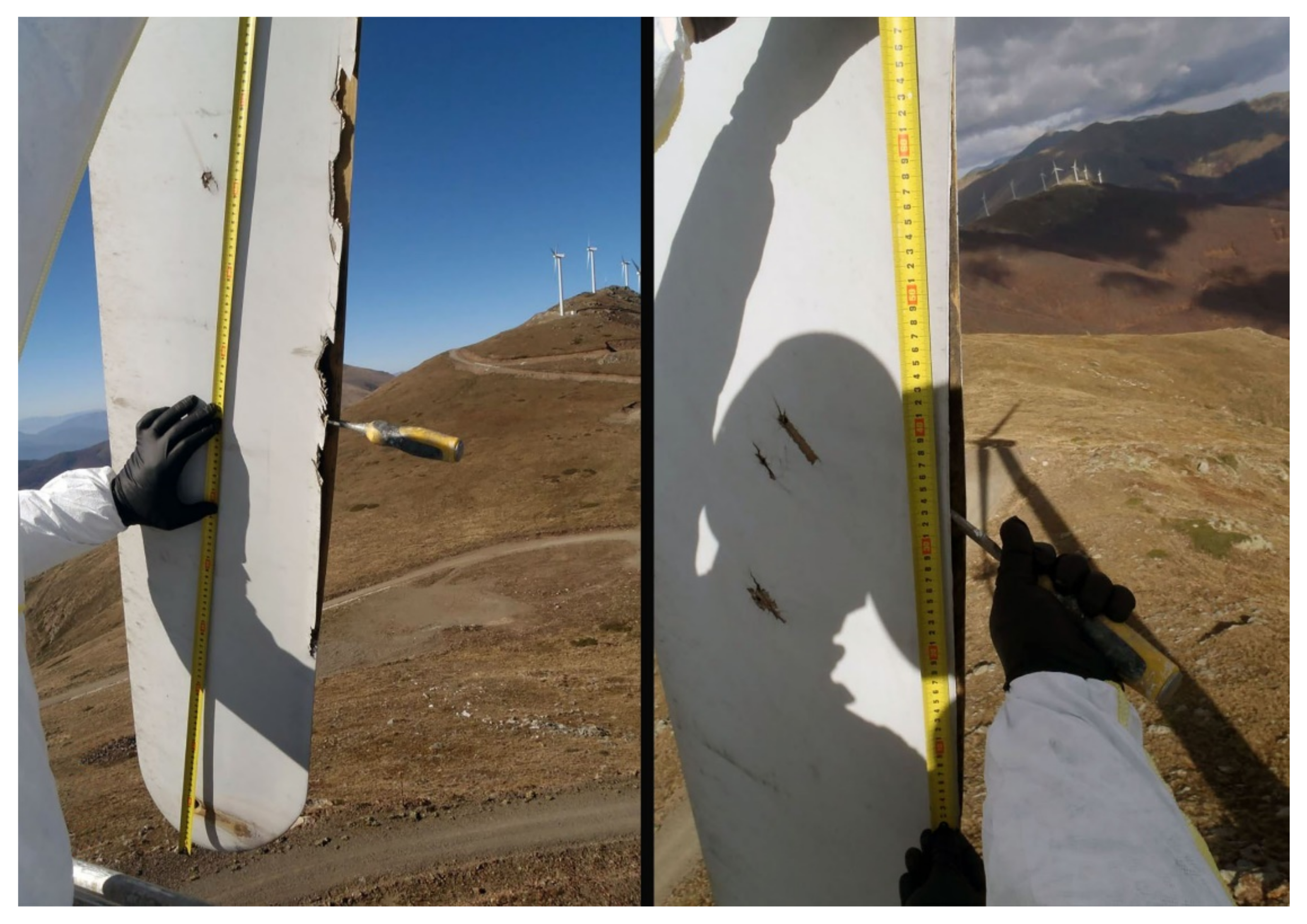
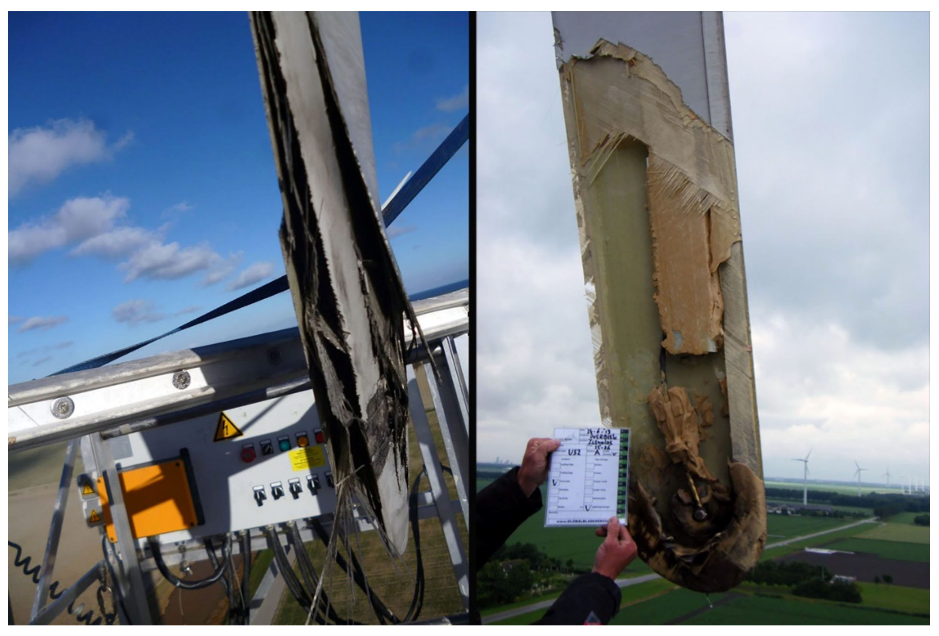
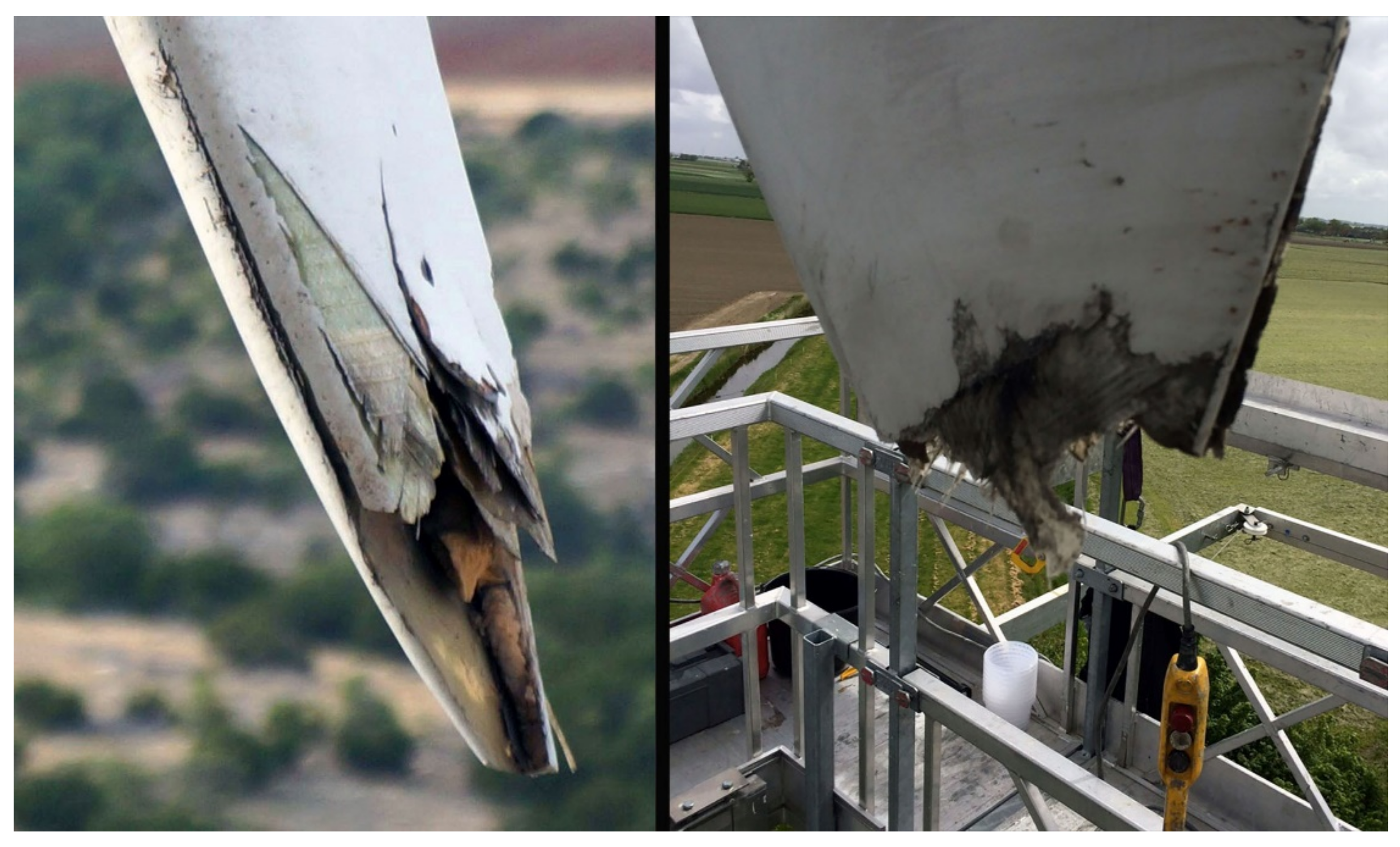
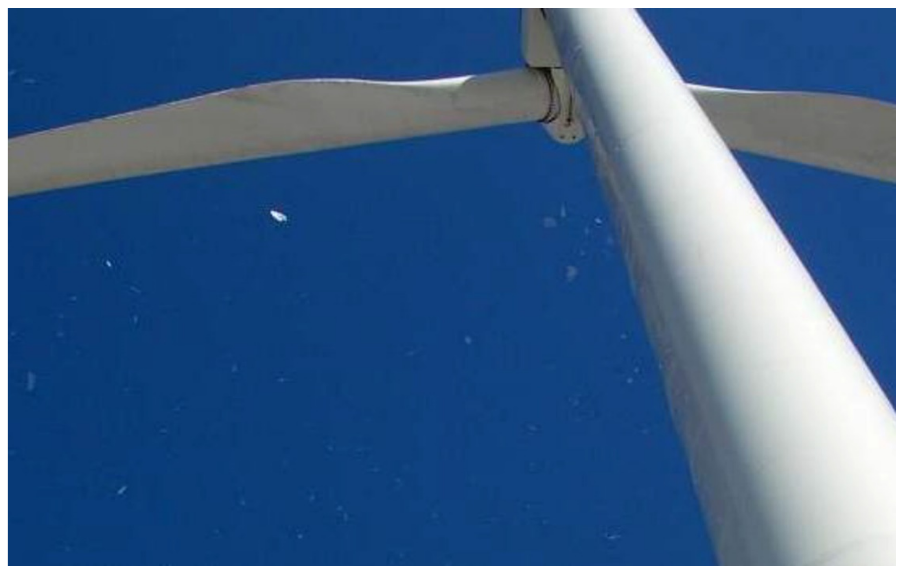
2.1. Damage from Lightning

The annual average frequency of lightning outages in Europe was between 3.9% and 8.0% from 1991 to 1998 [9]. In Japan, this figure was around 10–20% from 2002 to 2006 [20]. The recorded frequency of lightning outages implies a considerable probability of lightning strikes in wind turbines. According to [21], approximately 6% of wind turbines in Denmark and Germany could expect to be damaged annually by lightning strikes from 1992 to 1997. In a region in south central Texas in U.S.A., with an approximate frequency of 5–6 lightning strikes per km2 per year over a 3-year period, about 5% of the wind turbines with 1.5 MW rated power at a specific wind park experienced lightning damage to their blades [22]. Conclusively, according to field observations, wind turbines experience a significant number of lightning strikes during their lifetime [23,24].
The most frequent damage from lightning occurs on the WTBs [25,26,27,28,29,30]. More than 88% of lightning attachments occur within the outermost 1 m of the blade tip, where the thickness of the surface skin is around 2–10 mm. Yet, increasing risk of inboard puncture is also noted [31] with regard to the rest of the blade. Experimental results have shown that WTB rotation enhances the triggering of lightning [32].
Current lightning air-termination systems for rotor blades are designed to withstand about 98% of lightning strikes. Consequently, there is still a risk of local damage, particularly at the attachment point [33,34,35,36]. Such occurrences are caused in cases where the lightning conductor does not conduct as designed, causing lightning to create a shock wave in the blade’s inner space, due to air or internally concentrated moisture expansion, or both. The imposed over-pressures can stress the blade to subsequent failure [22].
Damage from lightning to wind turbine blades strongly depends on the structural materials. According to relevant experiments, polyvinyl chloride (PVC) and polyethylene terephthalate (PET) suffered pyrolysis and cracks inside when tested under severe temperature and increasing pressure strikes, while in cases of balsa wood blades, fibre breakage and large areas of delamination between the wooden material and the resin layer have been observed [37].
The most common types of damage in wind turbine blades caused by lightning strikes are as follows [38,39]:
Delamination: Delamination is normally caused by the localised build-up of pressure and abrupt expansion of the lightning arc column, combined with the structural degradation of the resin (due to incineration or overheating) between the laminate plies due to the temperature of the lightning channel. This causes the plies of the laminate to detach from each other (Figure 4). Usually, lightning-induced delamination is accompanied by punctures and burns on the laminate near the point of impact. Although delamination mainly occurs close to the blade tip, it can be found at any position between the blade tip and the hub.
The main problem with delamination is that it creates favourable conditions for the onset and development of cracks. This is especially troublesome in wind turbine blades, because of the fatigue loading that the structure is subjected to.
Debonding: Debonding consists of a localized separation of the upper and lower shells of the blade. It is usually present at the tip or at the trailing edge in the outer few meters of the blade (Figure 5). Usually debonding is caused because the heat generated from the lightning expands the air inside the blade, thus creating internal pressure. The vaporisation of condensed moisture trapped inside the blade can intensify this phenomenon. Debonding is mainly located very close to the tip of the blade, in distances lower than 1 m. However, there can be cases of shell debonding traced in distances up to 6 m from the tip. This is attributed to the fact that the blade is more robust near the hub, and therefore the expansion of air is not usually sufficient to cause the separation of the shells. Additionally, the blade tips are more likely to attract lightning.
It is noteworthy, that the concept of debonding usually refers to large scales (blade shells) compared to delamination (plies), while in materials science the reverse is true. In materials science, debonding usually refers to the events of failure of physical, chemical or mechanical forces that hold the interface between the fibre and the matrix together. Thus, in that context it refers to an interface between components of a ply (laminate). The delamination refers to the next level of the structure, which is the breakage of the interface between the laminates.
Shell detachment: The shell detachment consists of several meters of one or both shells completely detached from the load carrying structure (Figure 6). Usually, shell detachment starts with shell debonding. The mechanical forces generated by blades’ rotation, alongside any flutter induced by the flow characteristics (which change due to the geometry change) and the strong wind gusts during adverse weather conditions, eventually lead to shell detachment. Shell detachment is a rather rare damage caused by lightning strikes on wind turbine blades. In cases of shell detachment, the lightning strike point is usually located within the last 3 m of the blade tip, even if the damage affects several meters of the shell.
Tip detachment: Tip detachment refers to the complete detachment of several meters of the tip from the rest of the blade (Figure 7). It occurs when the lightning strike severely damages the structural laminate, such that the laminate cannot support the mechanical load and breaks. Consequently, tip detachment can be considered as the most critical case of WTB damage caused by lightning strikes. Tip detachment occurs rarely, most commonly in blades with a carbon fibre structure. For a 20 m blade length, tip detachment is located between 2 m and 7 m from the blade tip (namely, between 10% to 35% of the total blade’s length), where a direct lightning strike can be critical for the integrity of the relatively thin laminate of the load carrying structure [38]. This type of damage occurs when the lightning current severely damages the structural laminate, to the extent that the laminate cannot support the mechanical load and breaks [39].
An integrated and comprehensive analysis of WTB damage caused by lightning is presented in [38]. The analysis is based on 304 lightning incidents during a period of 5 years, occurring in the states of Texas, Kansas and Illinois, where the lightning flash density is within 2 and 8 flashes/km2 per year. The number of the involved wind turbines was 508, with a total rated power of 997 MW. The wind turbine blades were constructed of either fiberglass only (64.8% of the blades), or mixed fiberglass and carbon fibre (35.2% of the blades). All of the investigated wind turbine blades were designed and manufactured prior to the publication of IEC 61400-24 [40].
Given the total number of involved wind turbines and recorded lightning incidents, it is estimated that, on average, each wind turbine experienced blade damage due to lightning every 8.4 years [39]. In other words, it is estimated that during a period of 20 years, a wind turbine should expect on average 2–3 lightning strikes capable of inflicting damage.
The basic conclusions of this study can be summarized as follows:
  • More than 60% of the total damage occurred within the last meter of the blade, and 90% of all damage was located within the last 4 m. The remaining 10% of damage was found mainly from 5 m to 10 m from the blade tip. There were only three lightning incidents further inboard, at 15 m, 20 m and 22 m from the tip.
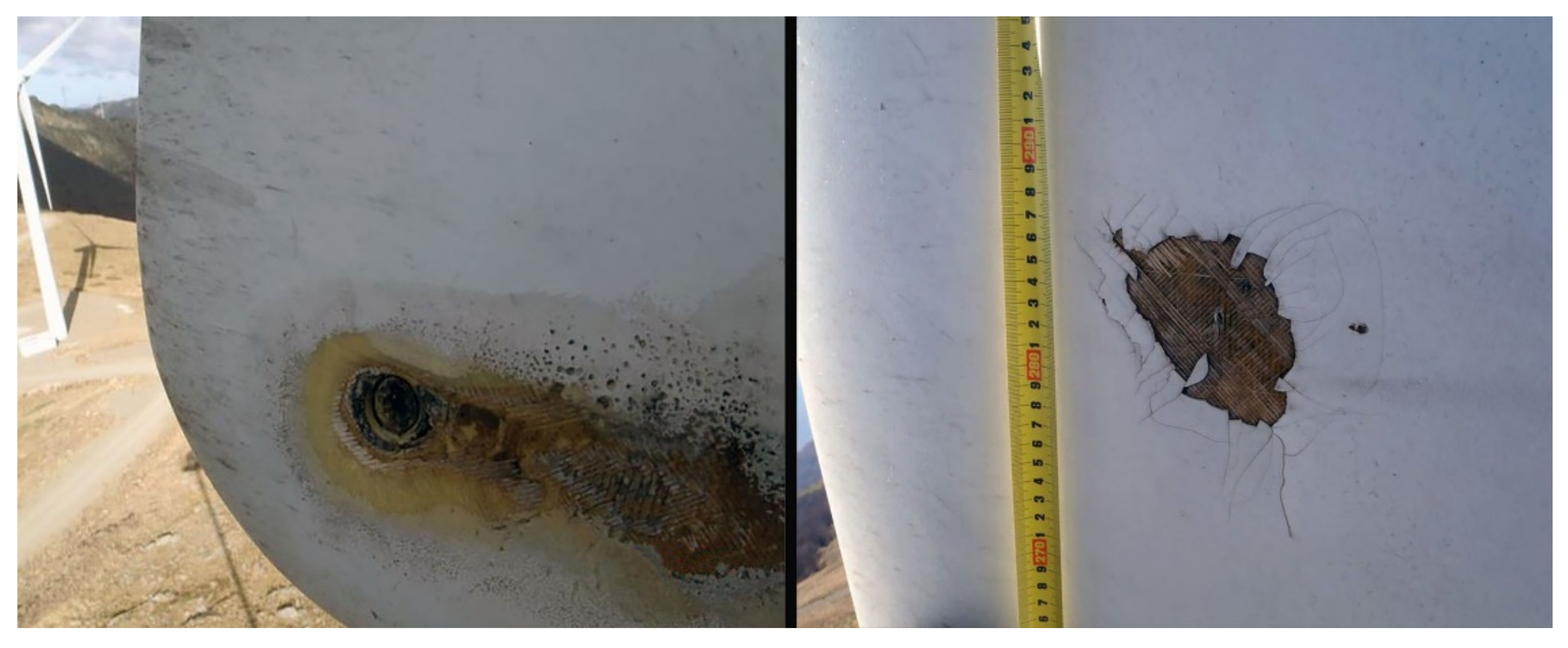
  • The most common type of lightning damage was delamination (72.4% of total blade damage), followed by debonding of the shells (24.7%). Shell and tip detachment each occurred in 1.4% of the investigated cases.
  • Wind turbines suffering damage to more than one blade are uncommon (2.7% in two blades and 0.7% in three blades). A single lightning stroke sweeping from one blade to another due to the blade rotation, different branches of a single lightning strike attaching to the blades, or different lightning events during a thunderstorm can be the potential causes of damage observed in more than one blade of the same wind turbine [39]. In any case, it is shown that damage to more than one blades of a single wind turbine is a rare event.
Lightning damage to wind turbine blades can impose serious costs, which are associated not only with the repair itself, but with the income lost due to the inevitable interruption of the turbine’s operation. The repair process for minor lightning damage, such as delamination, can take as little as 2–3 h, while more severe damage, such as detachment, may require a period of 3–5 days [39]. The cost of repairing blade damage caused by lightning can be as high as USD 30,000 [41].

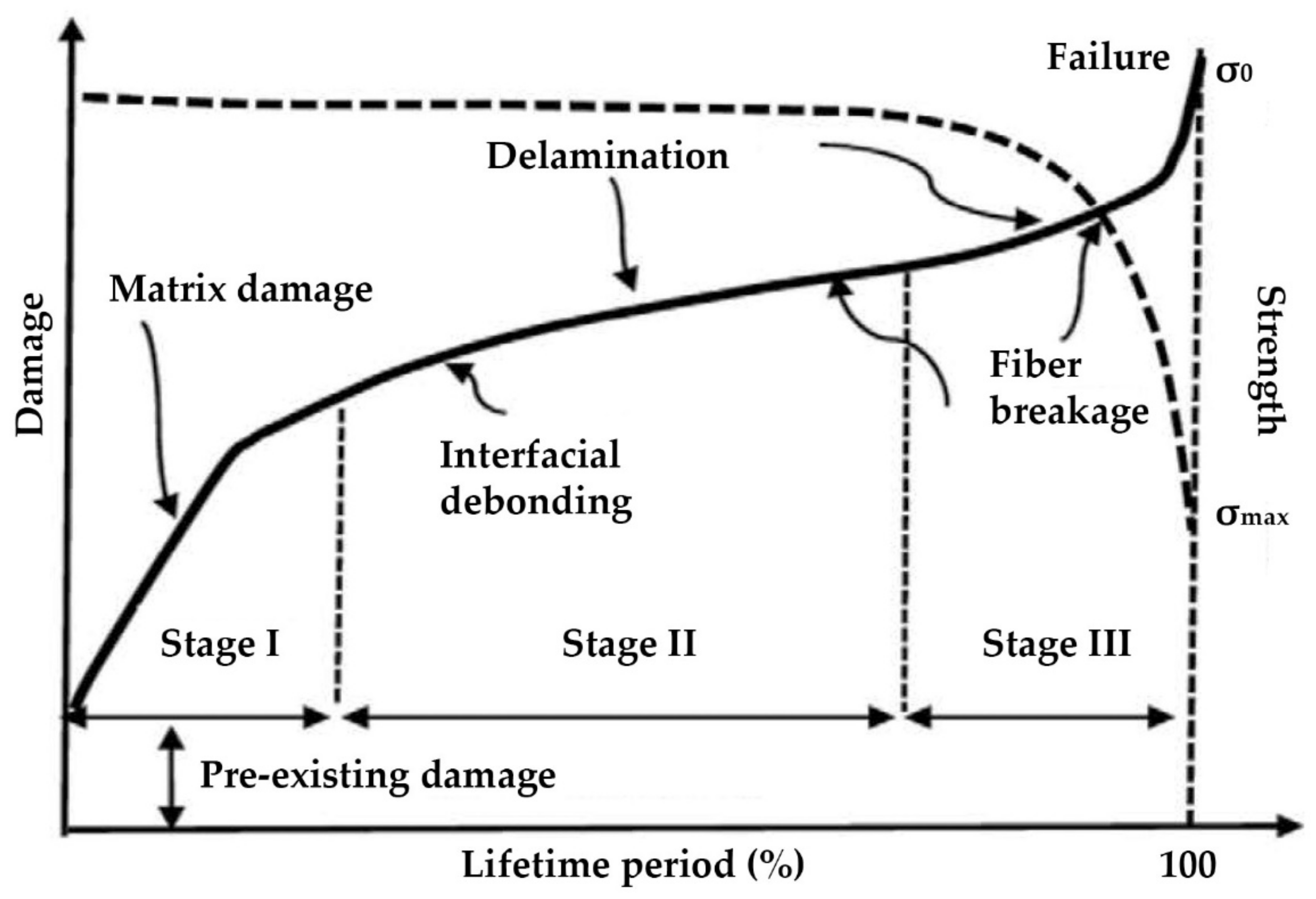
2.2. Fatigue Damage on Wind Turbine Blades

The term “fatigue” is used to describe the inability of a material to persistently withstand cyclic applied loads, which are fully tolerable when applied only once or for a few repetitions. During its operational lifetime, a wind turbine faces repetitious loads that contribute to the fatigue of the overall structure. Wind is the main source of these loads, which can be steady loads, transient loads from events such as gusts, periodic loads from wind shear and stochastic loads from turbulence. Additional loads can be developed by the turbine’s cyclic starts and stops, yaw error, yaw motion, resonance-induced loads from vibration of the structure and loads from gravity as well.
The main parameters affecting the potential occurrence and magnitude of fatigue loads and the resulting fatigue-induced damage in wind turbines are the surrounding environment and the land morphology of the installation area—more specifically, how the flow characteristics are affected by the land morphology and other obstructions.
Regarding the surrounding environment of a wind park, surface wear can be caused on the blades’ outer coating by corrosive pits from sand or rain impingement or even seawater, in the case of offshore or near-shore wind park installations. These initially small wear points would act as stress concentrators during cyclic loading, causing the initiation of localized cracking.
Moisture also can constitute another critical environmental parameter of fatigue damage caused mainly to the wind turbine blades. Despite the fact that glass fibre reinforced polyester (GFRP) blades are adequately water insulated, moisture can still penetrate into the blades’ inner material. Obviously the most fatigue-critical part of a wind turbine’s blade is the blade’s connection to the hub, because it has to bear all of the blade’s mechanical loads transferred and gathered at this particular point. For the connection of the blade with the turbine’s hub, a bolted joint is commonly used. The major effects of absorbed moisture on the laminates are as follows [42]:
  • Reduction of the glass transition temperature of the matrix resin
  • Damage to the interface between the fibres and the resin
  • Reduction of the cure-induced residual stresses through swelling, which may retard failure
  • Particularly in wind park installations in locations with subzero temperatures, the presence of moisture turning to ice. Ice formation can act as a wedge between the plies and leads to delamination propagation.
A composite material subjected to water and fatigue loads will exhibit increasing matrix cracking that, in turn, will accelerate water penetration. The effects of moisture absorption on the mechanical properties of GFRP blades are not accurately known [43]. The effects of moisture on the mechanical properties of fibre-reinforced plastics (FRP) are summarized in Table 1 [43].
However, the most important cause of fatigue damage is the load development from intensively fluctuating forces. Wind constitutes the main source of such forces, especially in cases of wind park installations in intensively turbulent wind conditions [44]. The land morphology of the installation area of a wind turbine may lead to the appearance of extensive wind turbulence conditions and the phenomenon of wind shear (Figure 8).
This intensively varying wind environment constitutes the fundamental source of iteratively fluctuating wind loads on the turbine’s structure, exposing it to operation under adverse fatigue conditions. Such unfavourable land morphologies can be abrupt changes of a mountain’s slope, steep cliffs downwards or upwards to the wind flow direction and, in general, any land geometries that result in separation of the atmospheric boundary layer.
Apart from the available land morphology, the wind flow on a wind turbine can be significantly affected by any physical or technical obstructions, such as, most commonly, the other wind turbines in the same wind park. Behind the wind turbine’s rotor, the wind flow exhibits roughly 40% reduced kinetic energy and increasing turbulence relative to the initial, unaffected flow. This area is the wind turbine’s wake. The term “aerodynamic shading” refers to the unpleasant situation of one wind turbine being inside the wake of another. This can occur in the case of short distances between the wind turbines and, of course, depending on the wind flow direction and the wind turbines’ relevant positions. The aerodynamic shading also constitutes another source of fatigue due to unsteady mechanical loads imposed by turbulent wind flow and shear effect. To avoid this probability, wind turbines should be sited properly, with adequate distances between them, accounting also for the prevailing wind direction, so as to ensure maximum efficiency and minimum impact on the normal atmospheric boundary layer.
Wind turbine blades, subject to repeated bending, are the most vulnerable components of the overall structure with regard to fatigue damage due to fluctuating forces. The fatigue damage initially appears as tiny cracks, usually located in the joining zone of the blade with the hub.
It is then concluded that the blade joints with the turbine’s hub constitute the most likely places for the appearance of fatigue damage, regardless of the source of the fatigue conditions. All of the factors with an unfavourable influence on a material’s fatigue strength are present in this area: stress concentration, bolt holes, built-in stresses, offsets, changes of section and application of different materials. Fatigue damage in the joining zone of the blade with the root appears initially as tiny cracks, which tend to become more severe over time.
The response of composite materials to fluctuating loads has been studied and defined for some specific material combinations, such as carbon fibres in an epoxy matrix for aerospace applications. According to [45], in anisotropic materials, fatigue damage accumulates in three stages versus time. During the initial load period (stage 1), a small drop in the material’s stiffness manifests, associated with the formation of minor damage. This first stage is followed by a much longer time period (stage 2), during which the damage seems to increase linearly with time and the stiffness falls gradually. If the stress is sufficiently high, a third stage (3) is observed, characterized by further and more severe damage, which ultimately lead to failure. This process is depicted in Figure 9 [46].
An image of typical fatigue damage in stage 1, in the form of cracks on the external surface, located in the transition zone between the root of the blade and the zone of airfoil profile, is presented in Figure 10 [45].
The shear effect also can be critical for the trailing edge adhesive joint, because it is more susceptible to damage due to the complex geometry, manufacturing technique and operating conditions [47].
The cost of manufacturing the three blades corresponds to 15–20% of the total manufacturing cost of a wind turbine [41]. The complete replacement of a destroyed blade with a new one can cost up to USD 200,000 [48]. The use of a crane imposes an additional cost of USD 350,000 per week [48]. These facts reveal the considerable economic load imposed by the costs associated with the repair of a blade after major damage caused by fatigue. The repair process for a severely damaged turbine blade can take several days, depending on the type and severity of damage, causing an additional cost burden due to income loss. Each day that a wind turbine remains inoperative imposes income losses ranging from USD 800 to 1600, depending on the available wind potential [48]. These unpleasant economic consequences can be prevented with the application of non-destructive and cost-effective techniques for the in-time detection of potential failures of the blades’ structural integrity due to fatigue loads, which will be presented in detail in Section 3.2.

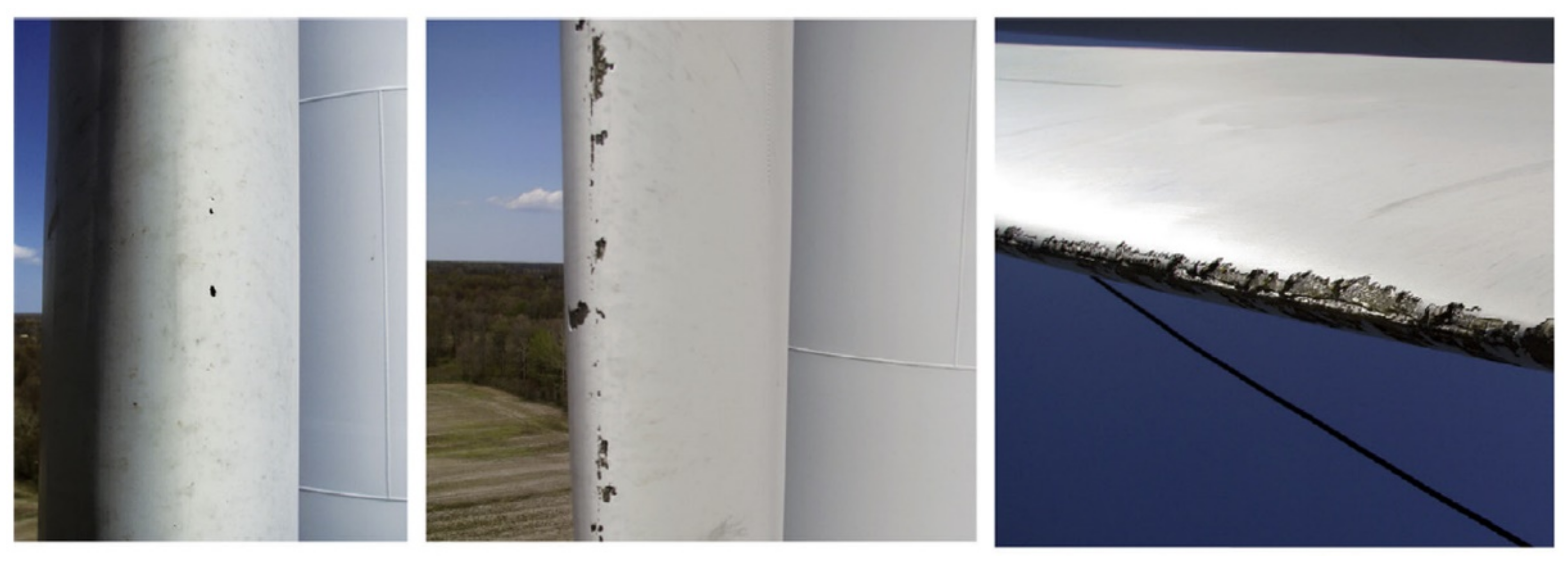
2.3. Leading Edge Erosion

In general, leading edge erosion of a wind turbine’s blade is the result of its exposure to:
  • airborne particulates, mainly in the form of rain, hailstone, sea-spray, dust and sand
  • UV light and humidity/moisture.
The first impact of this exposure is a gradual increase in the blade’s surface roughness, which negatively affects the blade’s aerodynamic performance by increasing its friction drag [49], and aerodynamic loss on the scale of 0.45–0.50% [50]. Depending on the level of leading edge erosion, drag can increase from 6 to 500% [51,52], leading in turn to an approx. 5% reduction in annual electricity production. The reduced lift and increased drag become more intensive with higher levels of erosion [53]. In extreme cases of leading edge erosion, the structural integrity of the blade can be affected (Figure 11).
Leading edge erosion can become an issue after only 2 years of turbine operation [50], much sooner than expected, with the tip being most susceptible to wear, but with erosion also exhibited on the more inboard portions of the blade [55]. As with all forms of environmental exposure, leading edge erosion is heavily site-dependent. In warm and arid climates, sand and dust may be a common type of airborne particulate and therefore may pose leading edge erosion problems, whereas in wetter, greener habitats, the problem may be non-existent. Likewise, at near-shore locations, the issue of sand erosion may be a considerable threat [56,57,58,59]. Leading edge erosion can be a result of rain, with the raindrops’ kinetic energy, diameter, temperature and sea salt content being critical parameters [56]. It has been also observed that careful handling of the blade during manufacturing, transport and installation is essential to avoid small tears or scratches that may act as initiation sites for further wear and erosion [60].
In order to present an estimation of the forces acting on a blade’s coating from airborne particles, let us assume a raindrop travelling with the wind. In general, the diameter of raindrops depends on the climatic conditions under which they are formed and the conditions of their transportation in the air. Typical raindrop diameters are commonly cited from 0.5 mm to 5 mm [50,61], while for mild to moderate rain rates, raindrop diameters range from 0.5 mm to 3 mm. Assuming water density at approximately 1000 kg/m3, the mass of a raindrop of spherical shape with a diameter of 3 mm is calculated at m = 0.014 gr.
The terminal velocity of a falling raindrop is also heavily dependent on the climatic conditions. The maximum free falling terminal velocity levels out at around 9 m/s for diameters in excess of about 3.5 mm [50,61]. Assuming a rain droplet with a terminal velocity of 8 m/s, fully entrained in a horizontal 20 m/s wind (i.e., assuming that the droplet is also travelling at this speed horizontally), strikes a rotating blade with a 90 m/s tangential tip speed, it is calculated that the impact velocity between the rain and blade does not drop below 80 m/s [45].
It is possible to calculate the force (average and peak) of impact using the following calculation. Assume the x-axis is the horizontal axis (along the wind), the y-axis is the vertical and z is perpendicular to the x-y plane. In that frame of reference, the velocity of a raindrop the moment before impacting the blade is vx = 20 m/s, vy = 8 m/s. Additionally, the wind turbine blade is rotating with a tip velocity of 90 m/s, which is parallel to the z-axis when the blade tip passes through the top and bottom of the rotation. The force on each axis is calculated with the change of momentum at each axis. The duration of the impact is proportional to the speed in that axis (note that on the x and y axes, the assumption is that the water drop stops moving, while on the z-axis it initially has zero velocity which after the impact is common to the blade tip). The resulting forces ( F x ,   F y ,   F z ) for each axis are added as vectors (Euclidean norm) and the resulting average force is calculated. Additionally, a triangular temporal distribution is assumed, which means that the peak impact force is twice the average force.
Given the assumptions of raindrop mass of m = 0.014 gr, diameter of d = 3 mm, wind speed 20 m/s, terminal velocity of 8 m/s and blade tip 90 m/s, the impact force F between the raindrop and the blade is calculated by using the Equation (1):
F = F x 2 + F y 2 + F z 2 F = 76 Nt
which means that every travelling droplet hitting the tip of the blade exerts on the blade’s coating approximately a force equivalent to the weight of a 7.6 kg mass.
The force exerted will obviously vary as the wind blade rotates. Nevertheless, the above estimation serves as a good tool to estimate the magnitude of impact forces on WTBs.
In the case of hailstones, the effects on a blade’s coating can be even worse, mainly due to the expected larger diameters. The average size of hailstones is dependent on site location [62]. Measurements on-site are considered the only certain method to obtain secure estimations regarding the likely average size of hail at a specific location. In northern Greece, for example, more than 85% of the hailstones recorded between 1984 and 1993 had sizes larger than 11 mm [63], while in the United Kingdom hailstone sizes in the range of 60 mm–90 mm have been recorded [64], although these are considered freak events.
As the diameter of hailstones increases, their mass mh and kinetic energy Ekin also increase (see Equation (2)). Additionally, with increasing diameter and mass, the terminal velocity of a hailstone Vh also increases according to Equation (3), where g is the gravitational acceleration, CD is the drag coefficient (0.5 for a sphere), ρair is the air density, Ah is the cross-sectional area of the hailstone in the direction of travel and rh is the hailstone radius [65].
E kin = 1 2 × m × V 2
V = 2 × m h × g C D × ρ air × A h = 8 3 g C D ρ h ρ air r h
Using Equation (3), assuming a density of 900 kg/m3 for the hailstone (this value varies widely) and of 1225 kg/m3 for the air, and a perfectly spherical hailstone shape and thus a drag coefficient of 0.5, the theoretical velocity for a range of hailstone diameters from 5 mm to 90 mm is calculated to be between 10 m/s and 40 m/s, respectively. Given the above hailstone velocities, it is conclusively proved that the maximum calculated impact velocity of a 15 mm and 30 mm diameter hailstone, impacting a blade tip with a tip speed of 90 m/s, in a 20 m/s wind field varies from 70 m/s to 120 m/s [50,61]. Given the above assumptions for the hailstones, the exerted forces can be calculated using the methodology for Equation (1). For hailstones of 15 mm and 30 mm diameter, the exerted forces at the tip of the blade are calculated to be from 1.7 kNt to 6.9 kNt, respectively.
Surface erosion of a wind turbine’s blade is not the only possible wear from hailstones. Hailstone impact can result in stress propagation throughout the blade coating [66], which, in turn, can result in delamination between plies, in the case of simultaneous blade bending due to shear forces. The constituents of the composite material may also fail, resulting in cracking through the matrix material or crushing of the reinforcing fibre. Both can have a significant effect on static and fatigue properties of the blade.
Seawater spray constitutes a special case of airborne particles, in the case of offshore or near- shore wind turbines, regarding the erosion of the blades’ leading edge. Apart from the fact that the seawater spray may affect the blades’ coating in the same way as raindrops with respect to the forces and pressures exerted, an additional impact comes from the transportation of sea salt crystals in the sea spray. The accumulation of sea salt crystals on the blade leading edge may lead to degradation of the blades’ aerodynamic performance and, possibly, to corrosive damage as well [67,68].
Leading edge erosion is directly related to income loss, due to degradation of the blades’ aerodynamic performance. As the damage concerns only a blade’s outer coating, the repair cost is not significant, on the condition, of course, that the damage is detected early and the required repair process is executed in time.

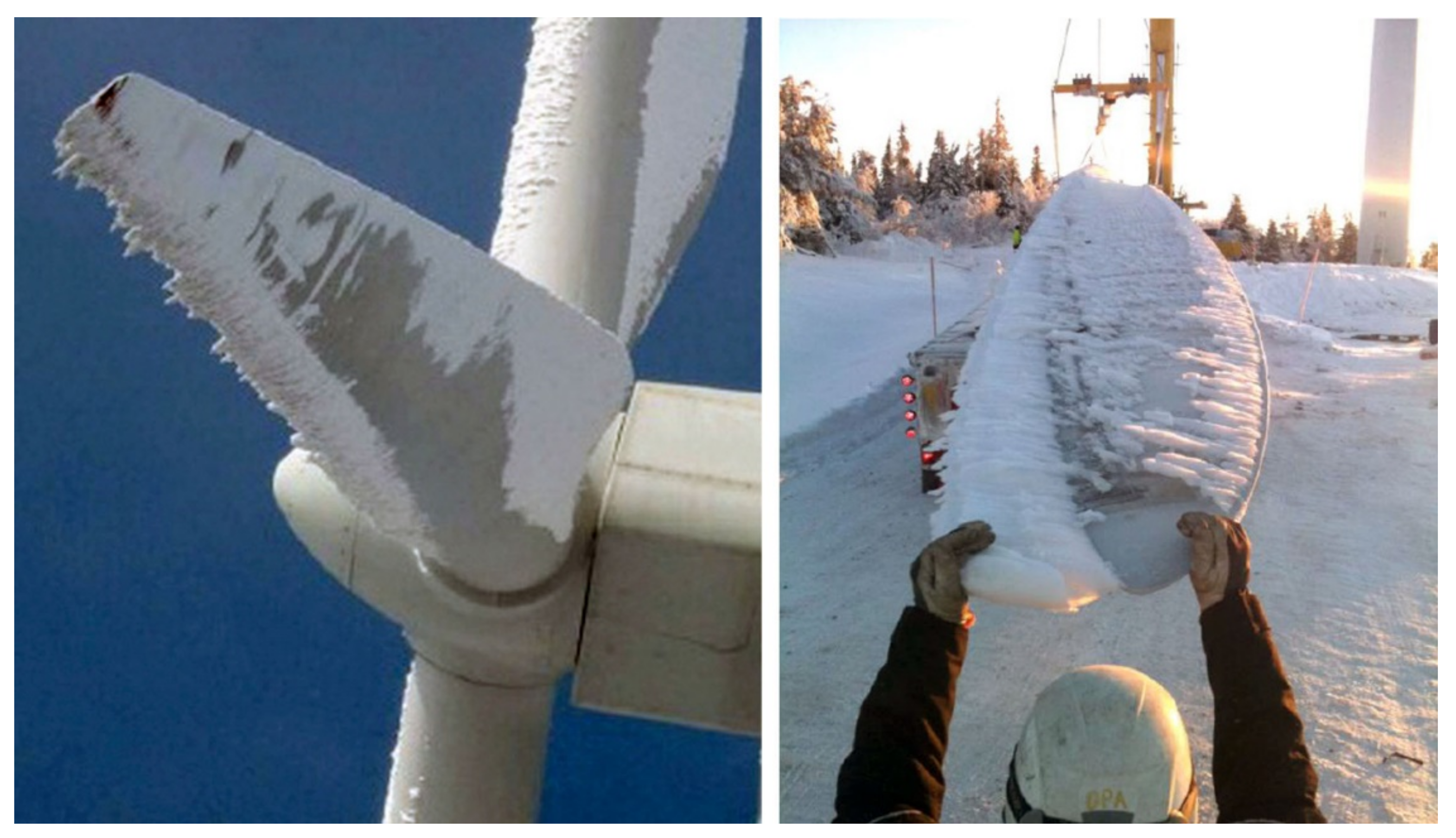
2.4. Damages from Icing

Atmospheric icing is defined as the accretion of ice or snow on structures exposed to the atmosphere. Two different types of atmospheric icing can be distinguished: in-cloud icing (rime ice or glaze) and precipitation icing (freezing rain or drizzle, wet snow). These are described as follows [69]:

2.4.1. Rime Ice

Rime ice is formed when the wind transfers supercooled liquid water droplets from clouds or fog. These droplets might freeze instantaneously as they hit a surface. In the case of small droplets, soft rime is formed, while hard rime is formed by large droplets.
Soft rime is a fragile, snow-like formation. Mainly, it consists of thin ice needles or flakes of ice. Soft rime starts forming in a very localised manner and grows triangularly into the windward direction. Soft rime usually ranges in density from 200 kg/m3 to 600 kg/m3 [70] and is easily removable. On the other hand, hard rime is an opaque and usually white ice formation. It adheres firmly onto surfaces and is very difficult to remove. Hard rime ice density ranges typically between 600 kg/m3 and 900 kg/m3 (ISO 12494) [70].
The formation of rime ice is asymmetrical, usually taking the shape of needles following the windward side of a structure. Rime ice is typically formed at temperatures from −20 °C to 0 °C. The most severe rime icing occurs at exposed ridges where moist air is lifted and wind speed increases.

2.4.2. Glaze

Glaze is the result of freezing rain or wet in-cloud icing. A smooth, transparent and homogenous ice layer is formed and strongly adheres on surfaces. Glaze is usually formed at temperatures from 0 °C to −6 °C with a density of around 900 kg/m3 [70].
Freezing rain occurs when the air aloft does not let water at temperatures below freezing to form ice crystals. As soon as freezing rain contacts a surface or the ground, it freezes. Conditions that favour freezing rain may be encountered in warm fronts or in valleys, where cold air may be trapped below warmer air aloft.
Wet in-cloud icing occurs when the surface temperature is close to 0 °C. The water droplets that hit a surface do not freeze completely. This results in the formation of a layer of liquid water which, due to wind and gravity, may flow around the surface and freeze also on its leeward side.

2.4.3. Wet Snow

Wet snow is formed by partially melted snow crystals with high liquid water content. The liquid content of the crystals increases the cohesive forces of this formation. Thus, it is able to adhere on an object’s surface. Wet snow accretion occurs when the air temperature is between 0 °C and +3 °C, with typical density from 300 kg/m3 to 600 kg/m3 [70]. If there is a temperature decrease after the wet snow accretion, then there can be ice formation.
Apart from the aforementioned categorisation, the icing conditions at a site are further described by the following additional parameters:
  • icing rate: ice accumulation per time (kg/h)
  • maximum ice load: maximum ice mass accreted at a structure (kg/m).
An icing event develops following the stages presented below [71], applicable to all structures exposed to atmospheric icing:

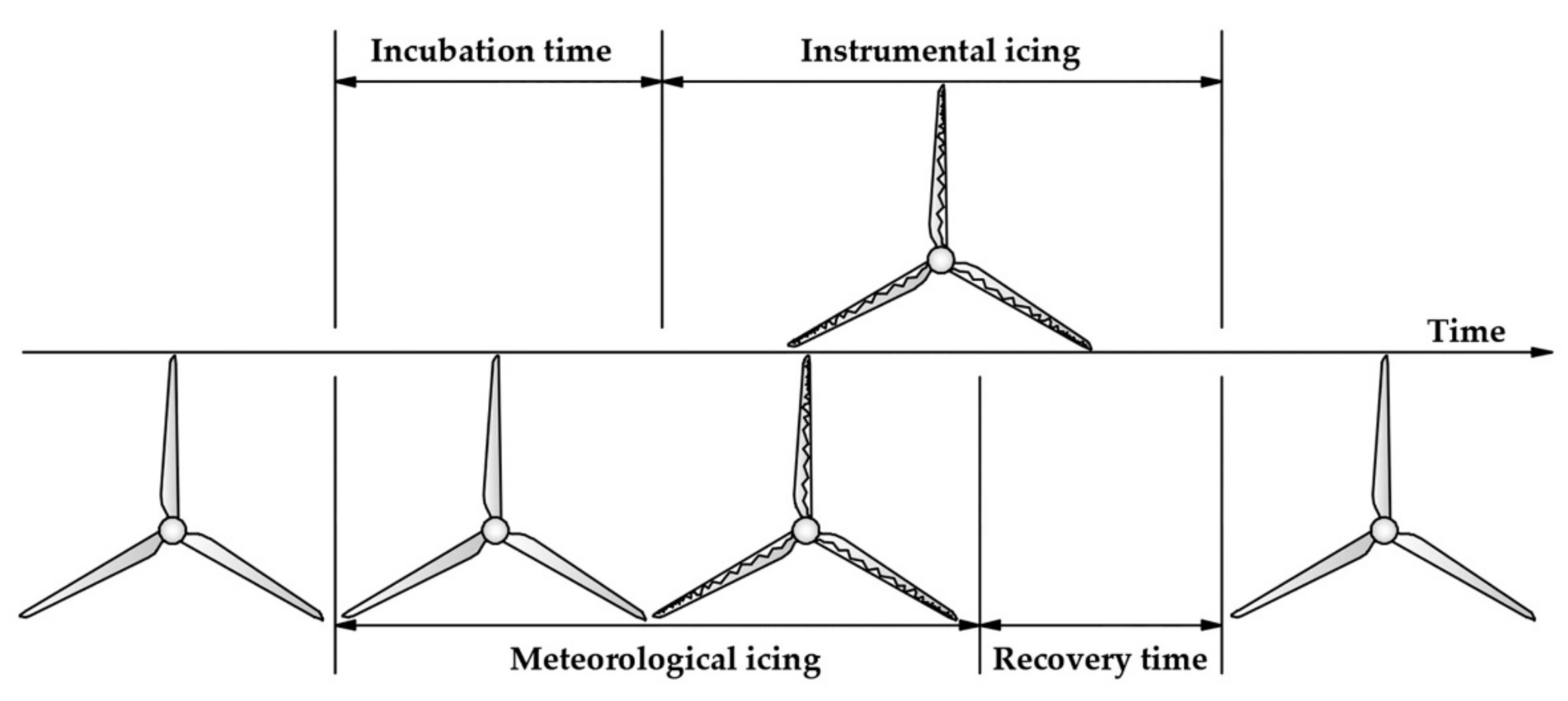
2.4.4. Meteorological Icing

Period during which the meteorological conditions (i.e., temperature, humidity, wind speed, etc.) favour ice formation (active ice formation).

2.4.5. Instrumental Icing

Period during which the ice remains at a structure. During that time the operation of the wind turbines is affected and their performance degrades.

2.4.6. Incubation Time

Delay period between the start of meteorological and start of instrumental icing (dependent on the surface and the temperature of the structure).
Figure 12 illustrates how the operation of a wind turbine is affected by icing according to the definitions described above [71]. When climate conditions for ice accretion are favourable (which signals the start of the meteorological icing period), then there is a certain delay period—the incubation time. The incubation time is the time required for the ice accretion to start on the wind turbine blades. The incubation time can be prolonged in an ideal case until the end of the meteorological icing, by using anti-icing measures, such as anti-icing coatings, heated surfaces, etc. As soon as ice has accumulated on the blade surfaces, which marks the start of instrumental icing, the wind turbine’s efficiency is affected. Ice accretion continues on the blade surfaces until the climate conditions for icing are not favourable anymore. However, ice will still remain on the blade surfaces for the recovery time, until it melts or falls off, with the end of the instrumental icing. The recovery time for the wind turbine blades can be significantly longer than the period of meteorological icing. By using de-icing measures, the recovery time can be shortened.
During the process of ice accumulation, the wind turbine is subjected to the above icing phases. Some of these phases (meteorological and maybe a part of instrumental icing) allow the turbine to remain operational. However, if the turbine’s limit for load bearing capacity is reached, or if there is a significant threat of ice-throw or the structural health of the turbine is endangered, then the turbine has reached its operational limit and must be stopped. The operational limit of the turbine will vary in each situation and is determined by the turbine design limits in response to environmental conditions and the surrounding safety limitations.
Ice accretion on the wind turbine blades produces significant change in the geometry of each blade’s surface, affecting its aerodynamic efficiency. As a result, the blade lift reduces while the drag increases, resulting in reduced power production and, eventually, in the turbine’s shutdown. Reduced power production occurs with an increasing number of lower than expected power stops, stops due to high vibration amplitude and stops due to faulty wind measurements.
Apart from the reduction in produced electricity, increasing vibrations and aerodynamic noise, imbalances in the blades, leading to increased wear in structural components such as connectors, couplers and gearbox, errors in nacelle wind speed measurements, as well as the risk of ice throw resulting in safety hazards should be expected as direct effects of icing [72,73,74,75]. Symmetrical icing of the blades reduces loads acting on the turbine components, whereas asymmetrical icing of the blades induces loads and vibrations in the tower, hub and nacelle assembly at a frequency synchronous to rotational speed of the turbine [74], imposing considerable fatigue loads. The aerodynamic changes in the iced blade can cause violent vibrations within the wind velocity operating range of the turbine [75]. Indirect consequences from the above effects might include reduced technical life, bodily injuries and material damage caused by falling ice.
An example of ice accretion on a turbine blade is presented in Figure 13 [69].
Iced up wind turbines blades and towers can pose a safety risk for wind parks visitors and staff, as large pieces of ice may be thrown from turbine blades during operation. Figure 14 is provided as an example of falling ice fragments [68].
Iced up wind turbine blades and towers can pose a safety risk for wind park visitors and staff, as large pieces of ice may be thrown from the turbine blades during operation. Figure 14 is provided as an example of falling ice fragments [69].
The cost related to icing mainly refers to the income loss imposed due to lower aerodynamic performance or even the interruption of the wind turbine’s operation, in the case of extreme accumulations of ice on the blades’ surface. The reduction in annual electricity production can exceed 10% due to icing or, in extreme cases with total shutdown of the turbine for a period of 2 months, it can be higher than 20% [77], leading to corresponding income loss.

3. Protection against Wind Turbine Blade Failures

Several techniques already have been applied in practise or studied in laboratory settings and presented in research articles on wind turbine blade protection from the aforementioned potential forms of damage. The most important of them are presented in the following sub-sections.

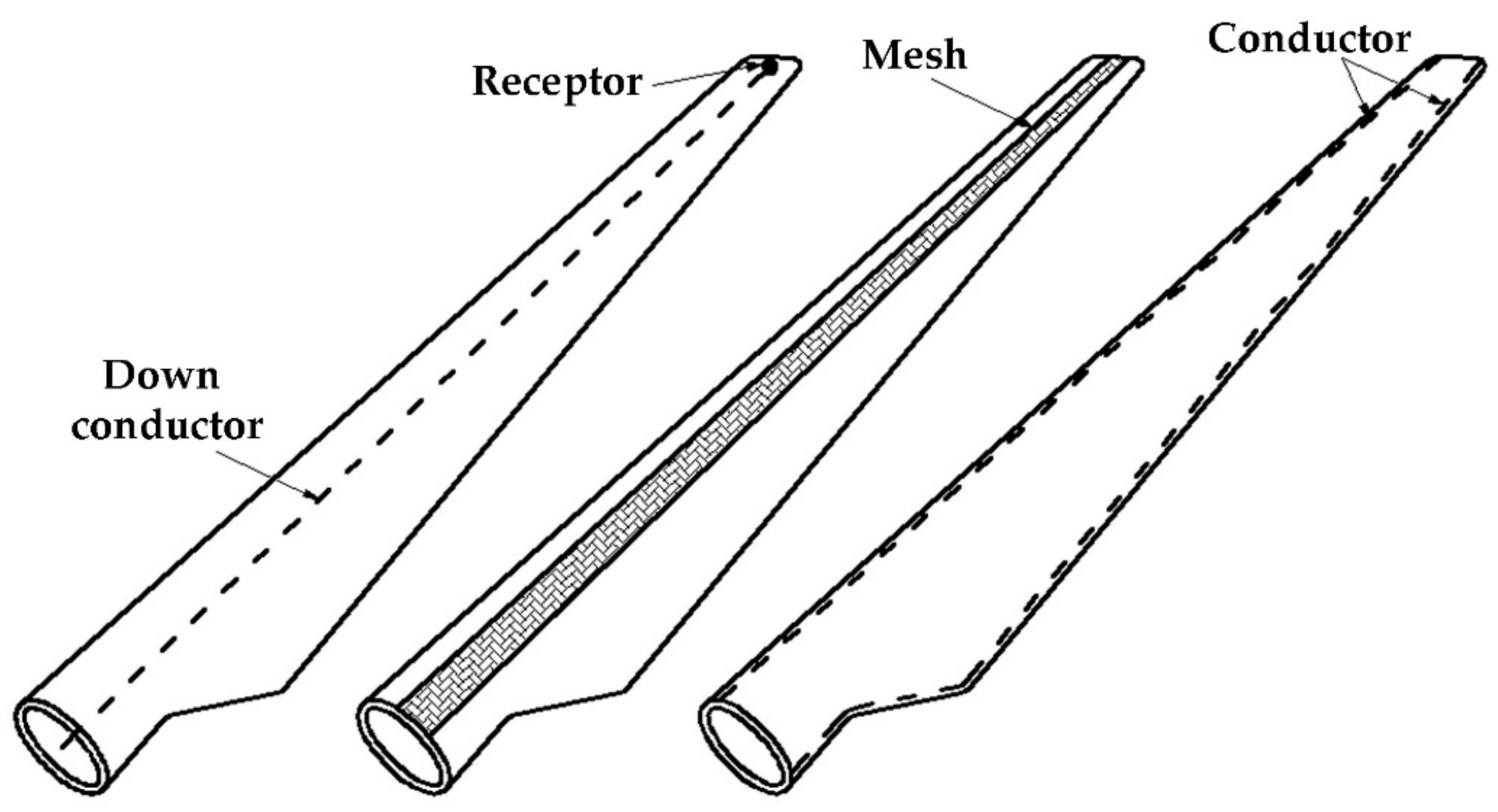
3.1. Protection from Lightning Damage

As the size of modern wind turbines increases, lightning protection becomes more and more important from an economic point of view, because the cost of repair for larger blades after a lightning strike is significantly higher than that for older, smaller blades. As they are installed at the top of the overall structure, the blades are commonly considered the most vulnerable part of the wind turbine in terms of lightning protection. Apart from the consequent damage to wind turbines blades, failure to ensure lightning protection may also negatively affect general attitudes toward wind energy exploitation.
Lightning protection on wind turbines can be approached in the following ways:
  • adequate driving of the lightning strike to a preferred point, such as the blade’s air termination system
  • installation of appropriate grounding, in order to guarantee the lightning current passage through the turbine’s structure into the earth, without causing any damage, including damage from strong electric or magnetic fields
  • minimisation of voltage gradients developed in and around the wind turbine.
The prerequisites and requirements for blade lightning protection systems (LPS) are defined in the IEC 61400-24 standard [40]. However, although a blade may be equipped with LPS, the probability of lightning damage can still exist, mainly due to interception failure of the air termination system during direct lightning attachment on the blade surface. Currently, there is no definite guidance or technology for guaranteed protection of wind turbines against lightning. Different methods and approaches have been introduced by the manufacturers, following the development of new wind turbines [20].
The different types of lightning protection installed in wind turbines blades are [40]:
  • air termination systems on the blade surfaces
  • high resistive tapes and diverters
  • down conductors placed inside the blade
  • conducting materials for the blade surface.
It is obvious that, regardless of the installed type of LPS, the metallic air terminations, strips, diverters and down conductors should be of sufficient cross sections in order to safely conduct the lightning current without any physical damage.
A commonly used protection method against lightning consists of a conductor installed inside the blade’s body [40], aiming to adequately drive the lightning current away from the blade’s mass. This conductor is connected to metal receptors (Figure 15), located at the blade’s tip, which in turn, by penetrating the blade’s surface, act as air terminations. This method is widely used for blades up to 60 m long [40], but is not likely to change for even longer blades. As already mentioned in Section 2.1, current LPS for wind turbines blades are designed to withstand 98% of lightning strikes.
Lightning receptors are the common technique applied in wind turbine blades for lightning protection. Yet, the observed number of lightning strike incidents proves that they cannot guarantee absolute protection [78]. An alternative protection method is to construct an isolated tower, which is installed a little apart from the wind turbine in order to block lightning discharge from it [78]. This method is expected to be fairly effective under the condition that wind direction is constant during thunderstorms. The lightning tower should be constructed on the windward side of a wind turbine. If the wind direction varies widely, it will be necessary to construct two or more towers. This approach is not practical from an economic viewpoint.
Another modern approach for lightning protection is the construction of the wind turbine blade with a non-metallic mesh. This non-metallic mesh is usually a continuous carbon fibre-reinforced thermoset resin that acts as a protection mesh on a glass fibre reinforced polymer (GFRP) composite surface. Experimental investigation of this technique has revealed that the carbon fibre mesh causes the striking current to spread outside the laminate instead of penetrating inside [79].

3.2. Protection against Fatigue

The major cause of wind turbine failure is fatigue. This is due to the vulnerability of wind turbine blades to cumulative fatigue damage imposed by the cyclic and repetitive nature of wind loading. Damage to wind turbine blades due to fatigue can be prevented with two alternative approaches:
  • adequate prediction of the blade’s material behaviour versus fatigue and its structural properties
  • appropriate selection of the wind park’s installation site and the optimum siting of the wind turbines.
The prediction of the dynamic behaviour of wind turbine blades constitutes one of the most important steps in the wind turbine design and development process, as it affects both the turbine’s efficiency, determining, eventually, the final electricity production, as well as the structural approach to the whole turbine’s construction, including the blades’ properties versus fatigue. The study of this dynamic behaviour can be undertaken with various methods of analysis [80], taking into account both the geometry and the material of the blade. Obviously this task depends on the manufacturer of the wind turbine and should be adequately approached using best practices and methods.
Among measures against fatigue that can be taken by the investor-owner of the wind park, first and above all, the proper siting of the wind turbines is the most efficient way to eliminate the fluctuating aerodynamic loading on the mechanical structure and, thus, the imposed fatigue consequences. In general, areas with small particles of soil or dust should be avoided. Additionally, as justified in Section 2.2, areas with intensive changes in mountain slopes and steep cliffs should not be selected for wind turbine installations. As a rule of thumb, the milder the land terrain, the less intensive the wind load variations will be [81].
Additionally, it has been found that turbulence intensity adversely affects the expected life to failure of a wind turbine blade [82]. Therefore, based on the data collected during a wind measurement campaign, or wind models, it is possible to determine the best location that minimises damage from fatigue.
After installation of the wind park, the only measure one can introduce against fatigue is the regular and valid inspection of wind turbine operations. Obviously, the main idea is that any potential fatigue-induced damage can be remedied easier and with lower cost if detected in time.
The inspection of wind turbine blades is a rather complicated task, as they exhibit an arbitrary curved surface, constitute complex multi-layered structures, are made with anisotropic materials and have variable thicknesses. Non-destructive testing (NDT) or non-destructive evaluation (NDE) is commonly used to monitor blade structures before, during and after installation. The most commonly applied NDT are [14]:
  • visual testing
  • ultrasonic testing
  • thermography
  • radiographic testing
  • acoustic emission.
Visual testing is a common method applied to inspect the discontinuities and cracks on wind turbine blade surfaces, especially in wind parks installed in isolated and difficult-to-access locations. It can be applied with the support of unmanned aerial vehicles (UAVs) equipped with photogrammetric or pan-tilt zoom cameras to provide images of the inspected structure. The latter are able to detect 2-cm width cracks from 200 m away [83]. The entire approach employs several artificial intelligence methods that aim to interpret the captured images and detect faults on the blade surfaces.
With the application of non-destructive ultrasonic evaluation, delamination, adhesive defects and resin-poor areas can be quickly, reliably and effectively detected. It is the most widely used non-destructive inspection technology for composite materials in industry. This technique is capable of detecting surface and subsurface faults. It is based on the analysis of the wave travelling along the blade. For the detection of faults, several mathematical and, recently, artificial intelligence methods have been proposed, aiming to overcome the noise introduced by the composite material and, of course, the complex geometry. The most popular studies are based on wavelet transform and pattern recognition [84], guided wave with signal processing [85], signal-to-noise processing [86] and simple harmonic motion analysis [87].
Infrared thermography can detect variations in the thermodynamic properties of the object and produce surface temperature patterns. Hot spots, due to degeneration of components or bad internal contact, can be identified in a simple and fast manner. It is a fast method and, due to this feature, it can be applied on large surfaces in short time. Among its main disadvantages, one can mention the misinterpretation of thermographs, which can be caused by reflections, dirt, etc. Yet, it has been proved that with the application of the appropriate filters, the noise generated by the application of this method can be detected and isolated [88]. In any case, the results of this method are also heavily based on the quality and the resolution of the employed thermographic camera, the type of heat source and, of course, the accuracy and the requirements of the investigated problem [89].
Radiographic testing is performed with the application of X-rays. The method is based on the different levels of absorption of X-ray photons as they pass through a material. The X-ray measurement data contain quantitative information about variations in density, which are caused by changes in material properties or internal delamination. X-rays combined with the new digital tomography technology enable 3D visualization of the structure of an inspected object [90].
The acoustic emission technique is based on the propagation of elastic waves through the mass of the material. The acoustic events are passively emitted by the material itself and not by an external excitation source [91]. The frequency of the acoustic event and any abnormalities in the wave’s propagation can indicate corresponding failures in the examined material’s structure, such as cracks, discontinuities, delamination, breakage, etc. The acoustic emission technique is appropriate to detect faults on wind turbine blades from their initiation stage; hence, it is usually employed for early damage detection [92]. Acoustic emission is performed with the installation of piezoelectric sensors properly allocated on the blade’s surface. An indicative allocation is presented in Figure 16 [93]. Cracks in particular are detected with either a single or a set of microphones [94]. The large amount of generated data requires appropriate processing, starting with the exclusion of noise and erroneous data. For this purpose, different mathematical approaches have been proposed in the literature, based on radical base function neural networks [95], Gaussian mixture models [96], wavelet transforms [97], etc.

3.3. Protection against Erosion

The protection of wind turbine blades against leading edge erosion is approached by applying plastic or elastomeric anti-corrosion protective tapes (e.g., abrasion-resistant polyurethane elastomers) or coatings on the blade’s leading edge (Figure 17 [98]).
The application of a polyurethane coating on the blade leading edges constitutes a commonly used technique for the protection of wind turbine blades against erosion. Such coatings have been widely used for the same reason on helicopter rotor blades. Polyurethane is characterized as segmented material, in the sense that its structure consists of both hard and soft segments. Hard segments have a direct positive impact on the stiffness and hardness of the material, while soft segments determine the toughness and the damping properties [99]. These combined features allow the development of strong, stiff, tough and composite coatings with good damping properties.
Moving one step ahead, an alternative approach against leading edge erosion is the application of multilayer coatings. Such multilayer protective coatings can be a combination of hybrid polycarbonatediol polyurethane-urea technology [100], polymer–metal laminates [101] or the introduction of nickel cobalt alloys into the main erosion protection material [102] and the application of electroformed nickel shields in the outer, higher speed parts of the blade and cheaper and lighter thermoplastic coatings in the intermediate regions closer to the hub [103]. These solutions aim to improve the strength and anticorrosive properties of the main protective polymer material.
The enhancement of the blades’ polymer coating with particle reinforcements at microscale and nanoscale constitutes another proposed technique for improved protection against leading edge erosion. Indicatively, the synthesis of epoxy coatings with surface treated ceramic nanoparticles [104] or the development of graphene-based coatings [105] have been proposed. The application of nanoengineering for the improvement of anti-corrosion coatings strongly depends on the manufacture of the coating, the manufacture and distribution of the nanoparticles, the coating’s surface processing, etc. [106,107].
The development of interpenetrated polymers based on polyurethane and epoxy resins constitutes another alternative solution, exhibiting specific attractive features, such as higher strength and improved damping properties [108]. The introduction of graphene to improve the mechanical and thermal properties of the interpenetrated polymer network also has been proposed [109], with positive results.
Another approach to improve the damping properties is the use of auxetic structures [110]. For this purpose, several studies are proposed [111,112]. Such an example is the use of chiral structures coupling uniaxial and rotational deformations to provide a negative Poisson’s ratio behaviour and high dissipation through shear strain energy; this feature is exploited by up-scaling the deformation mechanism of the chiral cell to design a damper that dissipates energy in the edgewise/shear modes, such as the ones occurring in wind turbine blades [113]. Other work describes the numerical and experimental assessment of using star-shaped biphase cells. The composite cells are intended for possible use as structural damping units to be located in maximum nodal strain positions corresponding to specific wind turbine blade modes [114].
Finally, as also stated in Section 2.3, the careful handling of the blade during manufacture, transport and installation is essential to avoid small tears or scratches that may act as initiation sites for further wear and erosion [115]. In general, a critical parameter is the surface roughness. The smoother the blade coating surface is, the more unfavourable the conditions for development of leading edge erosion will be [116]. However, the opposite opinion also exists, at least as far as the impact of airborne solid particles on blade erosion is concerned. According to this perspective, rugged, rough surfaces can exhibit improved anti-corrosion performance. This approach is bio-inspired and originated from the rough shells and skins of desert animals. Following this point, anti-corrosive rough bio-based surfaces have been developed, involving features and elements from desert scorpions [117,118].

3.4. Protection against Icing

The problems raised by ice formation on turbine blades can be treated with anti-icing or de-icing techniques. De-icing refers to the removal of ice from the blades. The aim is to reduce the recovery time from an icing event. Anti-icing aims to prevent or at least delay ice build-up on the wind turbines blades. Effective anti-icing methods will result in an increase in the incubation time (see Figure 12, Section 2.4).
Unfortunately, most of the research on wind turbine blade protection against icing is internally implemented by manufacturers, and therefore, relatively little information about the technical specifications and the performance of the techniques under development is available to the public. Currently, the commercially available and widely used and tested systems in independent R&D projects and in commercial applications are the hot air heating systems. These systems, and some more still in a trial phase, are presented in the next paragraphs.
De-icing: The hot air de-icing system operation is based on heat production and dissipation across the blade’s whole length, aiming to increase blade temperature and, therefore, concentrated ice melting. More specifically, hot air produced by electric resistance is propelled by a fan located in the root of the rotor blade over the ribs inside the blade all the way to the tip [119]. From the blade’s tip, the air circulates back to the root via the centre rib in the direction of the fan, creating, thus, a continuous flow. The continuous circulation of hot air inside the blade causes a temperature increase in the laminate above 0 °C, resulting, eventually, in the melting of ice or snow. This system, developed by ENERCON, has been tested thoroughly at the St. Brais site in Switzerland with satisfying results [120]. The power consumption of the rotor blade heating system is roughly 85 kW for the ENERCON E-82 and E-70 wind turbines, leading to a 4% reduction in the rated power production. It should be mentioned at this point that the loss of production due to icing in the winter months has been reported to be in excess of 10% annually in cold climates [121]. Alternatively, in wind turbines from other manufacturers, the electrical resistance is embedded inside the membrane or laminated on the surface of the turbine blade. Electrically heated foils can be heating wires or carbon fibres.
With all available versions of de-icing systems there is a potential risk, related to the high temperature induced in the blade’s interior. This temperature may pose considerable danger to the integrity of composite blades [122]. There are no reports regarding the long-term effects of heating systems on the structural integrity of large wind turbines.
The automatic operation of a de-icing system is another important field. The control of de-icing systems is based on ice detectors and blade surface temperature sensors. Additional temperature sensors are installed inside the blade to protect it from permanent damage due to overheating. Beyond the technical issues regarding safe and effective operation, which are described above, the correct timing for activation and deactivation of de-icing systems is an operation of major economic importance. The aim is to achieve the most cost-effective operating mode in terms of electricity consumed for heating versus the maximisation of electricity production from the wind turbine. To this end, several algorithms have been developed, based on a cluster of measurements received through an appropriate SCADA system and the exploitation of neural networks and artificial intelligence [123,124].
An innovative approach applied to ice protection systems introduces the use of ultrasonic guided waves (UGW). A few relevant research projects and review articles already have been reported [125,126,127]. UGW constitutes a non-destructive method, in which the waves propagate in a low frequency range, typically from 20 kHz to 100 kHz, along the length of the blade. According to wave theory, ultrasonic waves cause displacements and stresses inside a material as they propagate through it. Consequently, UGW possess, at least theoretically, the potential for removing ice accumulated on solid surfaces. Indeed, following the experiment presented in [128], an aluminium airfoil was de-iced once its resonance frequency had been matched with the applied 1 kHz UGW. The total procedure lasted 130 s in total, while the shear and normal stresses measured during the experiment reached 7.5 MPa and 25 MPa, respectively.
A target of obvious significance is the ability to predict icing and start up de-icing systems before there is ice on the blades. Such a possibility is not currently available. With all the developed de-icing systems, the process of removing the ice from the blade surfaces starts only after ice has been detected. A preventive de-icing, which would then be anti-icing, is not available today.
Finally, another potential drawback of de-icing systems comes from the fact that they are mainly applied on the blade’s leading edge. This implies a potential for secondary icing, namely the re-freezing and accumulation of initially melted ice on the unheated parts of the rotor blades.
Anti-icing: Anti-icing is mainly approached with the development of coatings with the ability to act as passive anti-ice surfaces [129]. In most cases, these coatings are constructed from hydrophobic materials that prevent water from remaining on their surfaces and, consequently, reduce ice formation. One big advantage of anti-icing methods is that no control system is needed. Although this approach sounds sensible, no general hydrophobic coating type has been reported to exhibit outstanding anti-icing results. This has been attributed to the fact that ice formation is affected by many factors, thus the importance of hydrophobicity is limited.
A first approach is the development of coatings with chemical freezing point depression, based on the leaching of depressors out of the paint matrix. Due to the leaching aspect, this effect is temporary and the technique is only suitable for applications that require ice-free surfaces for a short time.
The use of biochemical technologies for the prevention of ice formation on technical surfaces constitutes another promising idea. This biochemical approach is naturally adopted by organisms in polar and sub-polar climates (fish, amphibians, plants and insects), enabling them to survive in very low temperatures. In nature, this is achieved with antifreeze proteins on the organisms’ skin. Technically, this concept can be implemented by integrating substances with constitutive properties into a surface coating that can cause freezing point depression due to the configuration and conformation of the molecules. These molecules are described as thermal hysteresis proteins or, more commonly, as anti-freeze proteins (AFPs) [130]. They can selectively depress the freezing point without affecting the melting point of ice. This effect leads to a temperature difference between melting point and freezing point, known as “thermal hysteresis”.
Another approach is the development of coatings that contain hydrophilic centres in a hydrophobic environment. This allows water molecules to adhere to certain positions on the blade surface, yet the hydrophobic surroundings of these sites promote the removal of ice crystals.
In [131], an innovative dual de-icing and anti-icing system under development is presented. This either prevents ice accumulation (anti-icing) or removes any ice layer on a blade’s surface (de-icing). The method is based on the propagation of ultrasonic guided waves in composite blades to determine the optimal frequency and location of the transducers for ensuring wave propagation, causing the required level of energy concentration and resulting shear stress across the leading edge of the turbine’s blade. This allows specification and optimisation of the positioning of shakers, together with the magnitude and direction of harmonic forces required to induce sufficient acceleration to the blade surface for ice removal. A drawback of this method is the effect of blade distortion due to vibrations on the dynamical balancing of the turbine’s blades, which has not yet been investigated.
Most of the above presented approaches have been tested in labs, but only a few have been applied in the field. Hydrophobic coatings and biochemical technologies are generally either still subjects of lab research or at the early stages of field testing.
Finally, regarding the effects on public safety and health, wind turbine operations with iced up blades may not be permitted in certain countries or permitted only in the case of rime ice, as glaze ice is considered more dangerous. However, rime ice can be almost as dense as glaze ice, so there is no obvious reason to treat the cases differently. As visibility can be extremely poor under active icing conditions, warning signs should be closely spaced unless the area is accessible only via specific posted entry points. The areas of potential ice throw should be calculated and the proximity of developed areas, roads, and tourist infrastructure such as, for example, ski slopes, lifts, footpaths and parking areas must be taken into account when siting the turbines [132]. Warning signs of falling ice, visual warnings after icing events and horns or other active attention devices implemented before turbine start-up should be incorporated to help ensure public safety.
The cost associated with the installation and application of an anti-icing or a de-icing system in a wind turbine can reach 5% of the turbine’s total procurement cost [133].

3.5. Operating Strategies

The operating strategies for wind turbines to mitigate any possible damage to their blades are based on early detection and the actions required to prevent damage from becoming severe enough to negatively affect their operations and repair costs. They are performed with the collection of measurements of several critical parameters, such as temperature, noise, rotational speed, etc., gathered with the installation of relevant instruments (piezoelectric sensors, thermometers, optical sensors, etc.), or even cameras for optical inspection. The aforementioned process is always supported by the automatic inspection and control system that is commonly integrated into modern wind turbines, with the aim of detecting possible malfunctions or failures inside the nacelle, the bearing structure (pylon, foundation) and the rotor. Apart from the gathered measurement data, historical data and weather data also can be obtained.
Once the measurements and other data have been gathered and a fault has been detected, the proposed and applied operating algorithms aim to optimize the turbine’s operation in order to, depending on the damage severity, firstly prevent any further degradation of the turbine’s operational status and protect its structural integrity and, secondly, minimize the electricity production loss. Usually these operating algorithms are developed on the basis of specific mathematical models (e.g., Monte Carlo simulations to predict blade deterioration [134]) or on the experienced gained from technical facilities operating under the same conditions (e.g., data from offshore oil pumping stations can be used for offshore wind parks [135]). The potential decisions can be as follows:
  • shutdown of the wind turbine in case of severe damage or adverse weather conditions
  • selective shutdown or reduced operation, depending on the wind direction, of one or more wind turbines in case they affect the operation of the damaged turbine with their wake [136]
  • controlled operation of the damaged wind turbine in order to minimize power production loss, while concurrently executing the repair process.

4. Conclusions

A comprehensive analysis of the causes of potential wind turbine blade damage and the available methods and techniques to prevent or remedy them was presented in this article. As cumulative conclusions for the inspections, results and statistical data used in this work, the following can be stated:
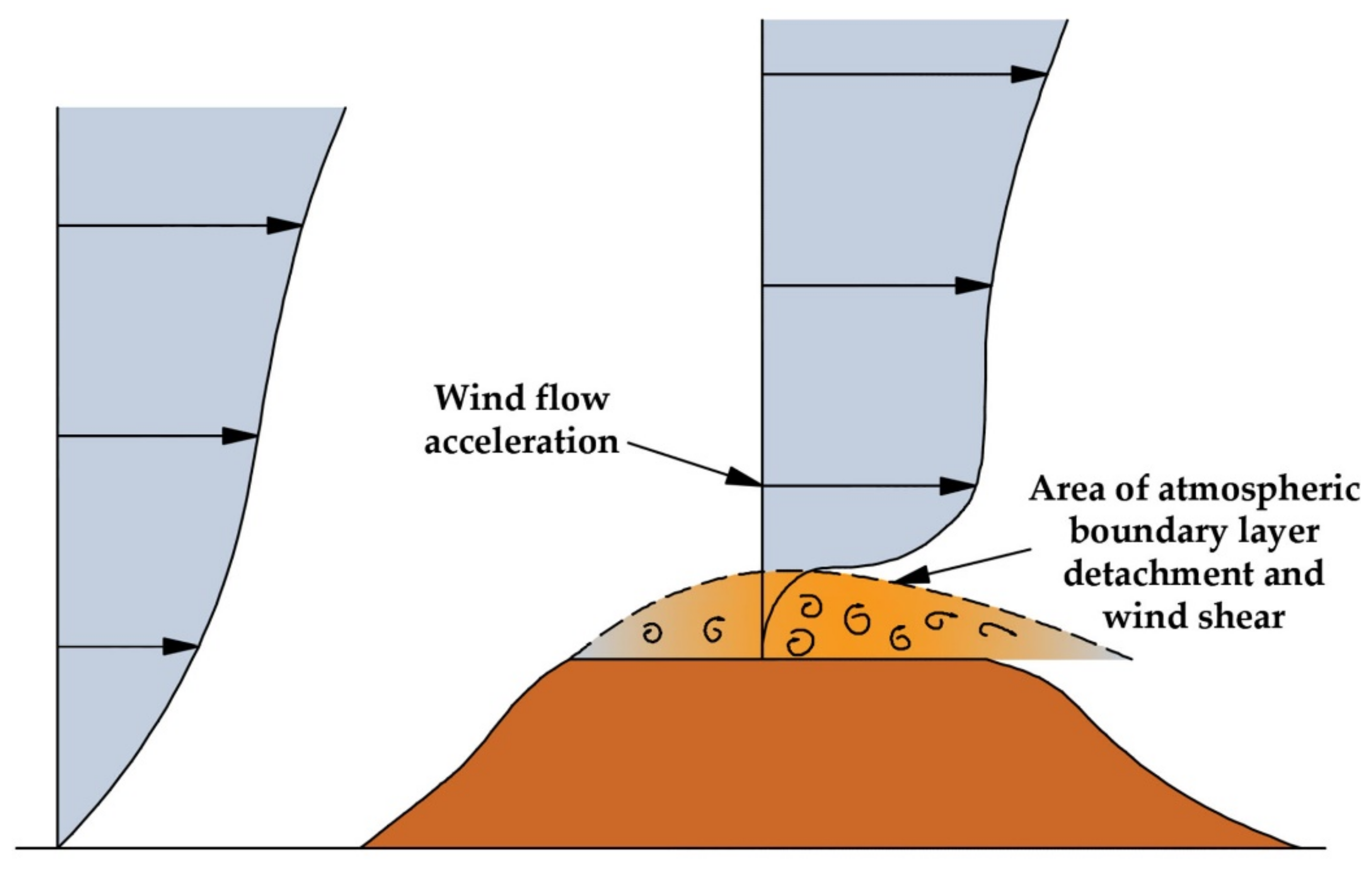
  • A common conclusion from the evaluation of potential causes of wind turbine blade damage is the ultimate significance of the surrounding environment and the existing weather conditions. The appropriate selection of a wind park’s installation site and the adequate siting of the wind turbines can eliminate induced fatigue loads. Additionally, in mild weather conditions, the probability of damage from lightning, icing and leading edge erosion also can be minimised.
  • In any case, it was revealed that there is no absolute method for guaranteed protection against any potential damage. All of the developed techniques and approaches contribute to the reduction of damage risk; however none of them can eliminate it.
  • In general, to facilitate operation and maintenance in adverse climates, a SCADA (supervisory control and data acquisition) system can be of considerable assistance, e.g., with ice detection, lightning damage or vibration monitoring. Important information includes, for example, ambient temperature, visibility at the site, web camera photos of rotor blades, turbine wind sensors, rotor rotating speed, etc. The supervisory system aims to detect and handle any damage at an initial stage, thus eliminating any potential technical or economic impact on the normal operation of the wind turbine and minimising repair costs.
  • Attempting a qualitative approach to the potential causes of wind turbine blade damage, we should mention that lightning can induce the most severe damage, even the total destruction of the blade. This can also be caused by fatigue loads after a long period of repetitive dynamic loading. However, destruction due to fatigue loads can be easily prevented with the appropriate selection of the installation site, the correct siting of the wind turbines and inspections of their operation. This, in general, cannot be achieved with lightning, because it commonly exists everywhere and abruptly, in a manner that cannot be either prevented or controlled. Hence, once it has occurred, the resulting damage cannot be avoided or limited in terms of severity. Conversely, although fatigue can potentially cause more severe and important damage to the wind turbine’s structure because it evolves over time, its impact can be prevented at the initial stage through proper inspections of the turbine’s operation, avoiding in this way its destructive results.
  • Icing cannot be destructive to the blade’s structure, except under very extreme conditions. However, the accumulation of ice on blade surfaces for long time periods (e.g., for an entire winter period) can lead to considerable reductions in wind turbine performance, eventually causing a corresponding negative impact to the project’s economic efficiency, analogous to, or even higher than, the cost of repairing a turbine blade struck by lightning.
  • Leading edge erosion seems to be the milder form of potential damage to a wind turbine blade, as it affects only the outer coating of the blade and cannot be a risk to the blade’s structure in any case. It can be easily repaired if it is detected in time.
  • All forms of blade damage can seriously affect the aerodynamic performance of the wind turbine and, consequently, its annual electricity production. For example, the reduction in electricity production due to icing can exceed 10%, while in extreme cases, it can reach 30%. Similarly, the increased roughness of the blade’s outer surface due to leading edge erosion can cause a 5% reduction in annual electricity production through an increased drag coefficient. Lightning and fatigue can also lead to significant production losses when the turbine has to be shut down for maintenance or repair, or, in the worst-case scenario, when the blade has been destroyed.
  • Wind turbine blade repair costs depend on the severity of the damage. A blade damaged by lightning may require up to USD 30,000 to be repaired, while the total cost of replacing a destroyed blade can cost up to USD 200,000. In general, the three blades of a wind turbine together account for 15% to 20% of the wind turbine’s total manufacturing cost. Additionally, each day during which a wind turbine remains inoperative due to blade damage imposes income losses ranging from USD 800 to USD 1600, depending on the available wind potential. These figures highlight the significance of wind turbine blade damage to the performance of a wind park and the economic efficiency of the wind project.

Author Contributions

Conceptualization, D.A.K.; methodology, D.A.K., N.P. and I.N.; validation, N.P.; investigation, D.A.K., N.P. and I.N.; resources, D.A.K., N.P. and I.N.; writing—original draft, D.A.K.; writing—review and editing, D.A.K., N.P. and I.N.; visualization, D.A.K.; supervision, D.A.K.; project administration, D.A.K.; funding acquisition, D.A.K. All authors have read and agreed to the published version of the manuscript.

Funding

This research was funded by the private company, Anemos Makedonias S.A.

Institutional Review Board Statement

Not applicable.

Informed Consent Statement

Not applicable.

Data Availability Statement

Not applicable.

Conflicts of Interest

The authors declare no conflict of interest. The funders had no role in the design of the study; in the collection, analyses, or interpretation of data; in the writing of the manuscript, or in the decision to publish the results.

References

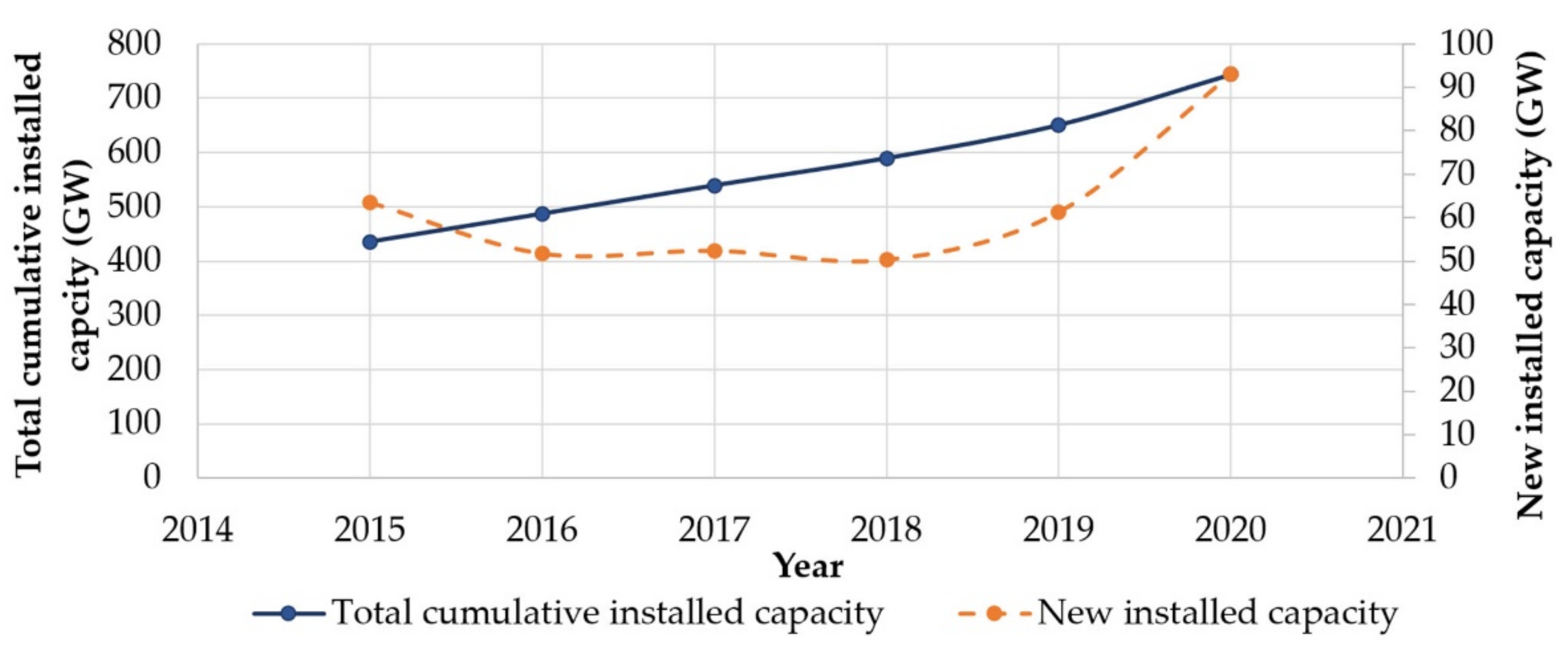
  1. World Wind Energy Association (WWEA). Worldwide Wind Capacity Reaches 744 Gigawatts—An Unprecedented 93 Gigawatts Added in 2020. Available online: https://wwindea.org/worldwide-wind-capacity-reaches-744-gigawatts/ (accessed on 17 June 2021).
  2. Lee, J.; Zhao, F. Global Wind Energy Council (GWEC). Available online: https://gwec.net/wp-content/uploads/2021/03/GWEC-Global-Wind-Report-2021.pdf (accessed on 10 September 2021).
  3. Global Energy Statistical Yearbook. Electricity Production. 2021. Available online: https://yearbook.enerdata.net/electricity/world-electricity-production-statistics.html (accessed on 10 September 2021).
  4. Kluskens, N.; Vasseur, V.; Benning, R. Energy Justice as Part of the Acceptance of Wind Energy: An Analysis of Limburg in The Netherlands. Energies 2019, 12, 4382. [Google Scholar] [CrossRef] [Green Version]
  5. Dimitris, A.L.; Katsaprakakis, D.A.; Christakis, D.G. The exploitation of electricity production projects from Renewable Energy Sources for the social and economic development of remote communities. The case of Greece: An example to avoid. Renew. Sustain. Energy Rev. 2016, 54, 341–349. [Google Scholar]
  6. Mishnaevsky, L., Jr.; Branner, K.; Petersen, H.N.; Beauson, J.; McGugan, M.; Sørensen, B.F. Materials for Wind Turbine Blades: An Overview. Materials 2017, 10, 1285. [Google Scholar] [CrossRef] [Green Version]
  7. Sutherland, H.J. A Summary of the Fatigue Properties Wind Turbine Materials. Available online: https://www.osti.gov/servlets/purl/12694 (accessed on 10 September 2021).
  8. Nagel, C.; Sondag, A.; Brede, M. Designing adhesively bonded joints for wind turbines. In Adhesives in Marine Engineering; Woodhead Publishing: Sawston, UK, 2012; pp. 46–71. [Google Scholar]
  9. Caithness Wind Farm Information Forum. Summary of Wind Turbine Accident Data to 31 March 2021. Available online: http://www.caithnesswindfarms.co.uk/AccidentStatistics.htm (accessed on 17 June 2021).
  10. Guo, J.; Jinfeng, C.L.; Jiang, C.D. Damage identification of wind turbine blades with deep convolutional neural networks. Renew. Energy 2021, 174, 122–133. [Google Scholar] [CrossRef]
  11. Movsessian, A.; Cava, D.G.; Tcherniak, D.G. An artificial neural network methodology for damage detection: Demonstration on an operating wind turbine blade. Mech. Syst. Signal Process. 2021, 159, 107766. [Google Scholar] [CrossRef]
  12. Reddy, A.; Indragandhi, V.; Ravi, L.; Subramaniyaswamy, V. Detection of Cracks and damage in wind turbine blades using artificial intelligence-based image analytics. Measurement 2019, 147, 106823. [Google Scholar] [CrossRef]
  13. Dua, Y.; Zhoua, S.; Jing, X.; Peng, Y.; Wu, H.; Kwok, N. Damage detection techniques for wind turbine blades: A review. Mech. Syst. Signal Process. 2020, 141, 106445. [Google Scholar] [CrossRef]
  14. Márquez, F.P.G.; Chacón, A.M.P. A review of non-destructive testing on wind turbines blades. Renew. Energy 2020, 161, 998–1010. [Google Scholar] [CrossRef]
  15. Chandrasekhar, K.; Stevanovic, N.; Cross, E.J.; Dervilis, N.; Worden, K. Damage detection in operational wind turbine blades using a new approach based on machine learning. Renew. Energy 2021, 168, 1249–1264. [Google Scholar] [CrossRef]
  16. Yang, Y.; Sørensen, J.D. Cost-Optimal Maintenance Planning for Defects on Wind Turbine Blades. Energies 2019, 12, 998. [Google Scholar] [CrossRef] [Green Version]
  17. Gao, Z.; Liu, X. An Overview on Fault Diagnosis, Prognosis and Resilient Control for Wind Turbine Systems. Processes 2021, 9, 300. [Google Scholar] [CrossRef]
  18. Wind Power Monthly. How to Service and Maintain a Wind Turbine Blade. Available online: https://www.windpowermonthly.com/article/1137943/service-maintain-wind-turbine-blade (accessed on 9 September 2021).
  19. Steigmann, R.; Iftimie, N.; Savin, A.; Sturm, R. Wind turbine blade composites assessment using non-contact ultrasound method. J. Clean Energy Technol. 2016, 4, 440–443. [Google Scholar] [CrossRef]
  20. Ideno, M.; Seki, K. Study on Improvement of Performance of wind power generation system and lightning damage. In Proceedings of the 28th International Conference on Lightning Protection, Kanazawa, Japan, 18–22 September 2006; pp. 1585–1589. [Google Scholar]
  21. Lightning Protection of Wind Turbines. Contract JOR3-CT95-0052. Publishable Final Report. Research Funded in Part by the European Commission in the Framework of the Non Nuclear Energy Programme JOULE III. Available online: https://cordis.europa.eu/docs/projects/files/JOR/JOR3950052/47698081-6_en.pdf (accessed on 27 July 2021).
  22. Kithi, R. Case Study of Lightning Damage to Wind Turbine Blade. 2008. Available online: http://www.lightningsafety.com/nlsi_lhm/wind_blade_damage.pdf (accessed on 27 July 2021).
  23. Wilson, N.; Myers, J.; Cummins, K.L.; Hutchinson, M.; Nag, A. Lightning attachment to wind turbines in Central Kansas: Video observations, correlation with the NLDN and in-situ peak current measurements. In Proceedings of the EWEA Annual Event, Vienna, Austria, 4–7 February 2013. [Google Scholar]
  24. Cummins, K.L.; Zhang, D.; Quick, M.G.; Garolera, A.C.; Myers, J. Overview of the Kansas Windfarm 2013 Field Program. In Proceedings of the International Lightning Detection Conference, Tucson, AZ, USA, 12–15 March 2014. [Google Scholar]
  25. Wang, D.; Takagi, N.; Watanabe, T.; Sakurano, H.; Hashimoto, M. Observed characteristics of upward leaders that are initiated from a windmill and its lighting protection tower. Geophys. Res. Lett. 2008, 35, L02803. [Google Scholar] [CrossRef]
  26. Ishii, M.; Saito, M.; Natsuno, D.; Sugita, A. Lighting current observed at wind turbines at winter in Japan. In Proceedings of the International Conference on Lightning and Static Electricity, Seattle, WA, USA, 18–20 September 2013. [Google Scholar]
  27. Kusiak, A.; Li, W. The prediction and diagnosis of wind turbine faults. Renew. Energy 2011, 36, 16–23. [Google Scholar] [CrossRef]
  28. Kong, C.; Bang, J.; Sugiyama, Y. Structural investigation of composite wind turbine blade considering various load cases and fatigue life. Energy 2005, 30, 2101–2114. [Google Scholar] [CrossRef]
  29. Amirat, Y.; Benbouzid, M.E.H.; Al-Ahmar, E.; Bensaker, B.; Turri, S. A brief status on condition monitoring and fault diagnosis in wind energy conversion systems. Renew. Sustain. Energy Rev. 2009, 13, 2629–2636. [Google Scholar] [CrossRef] [Green Version]
  30. Rodrigues, R.B.; Mendes, V.M.F.; Catalão, J.P.S. Protection of wind energy systems against the indirect effects of lightning. Renew. Energy 2011, 36, 2888–2896. [Google Scholar] [CrossRef]
  31. Madsen, S.F.; Holboll, J.; Henriksen, M.; Bertelsen, K.; Erichsen, H.V. New test method for evaluating the lightning protection system on wind turbine blades. In Proceedings of the 28th International Conference on Lightning Protection, Kanazawa, Japan, 18–22 September 2006. [Google Scholar]
  32. Wen, X.; Qu, L.; Wang, Y.; Chen, X.; Lan, L.; Si, T.; Xu, J. Effect of Wind Turbine Blade Rotation on Triggering Lightning: An Experimental Study. Energies 2016, 9, 1029. [Google Scholar] [CrossRef]
  33. Cotton, I.; Jenkins, N.; Pandiaraj, K. Lightning protection for wind turbine blades and bearings. Wind Energy 2001, 4, 23–37. [Google Scholar] [CrossRef]
  34. Peesapati, V.; Cotton, I. Lightning protection of wind turbines—A comparison of real lightning strike data and finite element lightning attachment analysis. In Proceedings of the 1st International Conference of Sustainable Power Generation Supply (Supergen), Nanjing, China, 6–7 April 2009. [Google Scholar]
  35. Madsen, S.F.; Erichsen, H.V. Numerical model to determine lightning attachment point distributions on wind turbines according to the revised IEC 61400-24. In Proceedings of the International Conference on Lightning and Static Electricity (ICOLSE), Pittsfield, MA, USA, 15–17 September 2009. [Google Scholar]
  36. Naka, T.; Vasa, N.J.; Yokoyama, S.; Wada, A.; Asakawa, A.; Honda, H. Study on lightning protection methods for wind turbine blades. IEEJ Trans. Power Energy 2005, 125, 993–999. [Google Scholar] [CrossRef] [Green Version]
  37. Yan, J.; Wang, G.; Li, Q.; Zhang, L.; Yan, J.D.; Chen, C.; Fang, Z. A Comparative Study on Damage Mechanism of Sandwich Structures with Different Core Materials under Lightning Strikes. Energies 2017, 10, 1594. [Google Scholar] [CrossRef] [Green Version]
  38. Garolera, A.C. Lightning Protection of Flap System for Wind Turbine Blades. Ph.D. Thesis, Technical University of Denmark, Lyngby, Denmark, September 2014. Available online: http://orbit.dtu.dk/files/118015819/PhD_Thesis_Anna_Candela_Garolera.pdf (accessed on 27 July 2021).
  39. Garolera, A.C.; Madsen, S.F.; Nissim, M.; Myers, J.D.; Holboell, J. Lightning damage to wind turbine blades from wind farms. IEEE Trans. Power Deliv. 2016, 31, 1043–1049. [Google Scholar] [CrossRef]
  40. Wind Turbines—Part 24: Lightning Protection, 1st ed.; IEC 61400-24; IEC: London, UK, 2010.
  41. Shohag, M.A.S.; Hammel, E.C.; Olawale, D.O.; Okoli, O.I. Damage mitigation techniques in wind turbine blades: A review. Wind Eng. 2017, 41, 185–210. [Google Scholar] [CrossRef]
  42. Bulder, B.H.; Bach, P.W. A Literature Survey on the Effects of Moisture on the Mechanical Properties of Glass and Carbon Fibre Reinforced Laminates; ECN-C-91-033; U.S. Department of Energy: Washington, DC, USA, 1991.
  43. Reifsnider, K.F. Fatigue of Composite Materials; Elsevier: Amsterdam, The Netherlands, 1991. [Google Scholar]
  44. Bergeles, G. Wind Converters; Simeon Editions: Athens, Greek, 2005. [Google Scholar]
  45. Marín, J.C.; Barroso, A.; París, F.; Cañas, J. Study of fatigue damage in wind turbine blades. Eng. Fail. Anal. 2009, 16, 656–668. [Google Scholar] [CrossRef]
  46. D’Amore, A.; Grassia, L. Principal Features of Fatigue and Residual Strength of Composite Materials Subjected to Constant Amplitude (CA) Loading. Materials 2019, 12, 2586. [Google Scholar] [CrossRef] [Green Version]
  47. Chen, C.; Li, H.; Wang, T.; Wang, L. Influence of Structural Configurations on the Shear Fatigue Damage of the Blade Trailing-Edge Adhesive Joint. Appl. Sci. 2020, 10, 2715. [Google Scholar] [CrossRef] [Green Version]
  48. Mishnaevsky, L., Jr.; Thomsen, K. Costs of repair of wind turbine blades: Influence of technology aspects. Wind Energy 2020, 23, 2247–2255. [Google Scholar] [CrossRef]
  49. Schramm, M.; Rahimi, H.; Stoevesandt, B.; Tangager, K. The Influence of Eroded Blades on Wind Turbine Performance Using Numerical Simulations. Energies 2017, 10, 1420. [Google Scholar] [CrossRef] [Green Version]
  50. Hasager, C.B.; Vejen, F.; Skrzypiński, W.R.; Tilg, A.M. Rain Erosion Load and Its Effect on Leading-Edge Lifetime and Potential of Erosion-Safe Mode at Wind Turbines in the North Sea and Baltic Sea. Energies 2021, 14, 1959. [Google Scholar] [CrossRef]
  51. Elert, G.; Volynets, I. Diameter of A Raindrop. 2001. Available online: http://hypertextbook.com/facts/2001/IgorVolynets.shtml (accessed on 8 March 2021).
  52. Villermaux, E.; Bossa, B. Single-drop fragmentation determines size of distribution of raindrops. Nat. Phys. 2009, 5, 697–702. [Google Scholar] [CrossRef]
  53. Imeson, A.C.; Vis, R.; de Water, E. The measurement of water-drop impact forces with a piezo-electric transducer. CATENA 1981, 8, 83–96. [Google Scholar] [CrossRef]
  54. Gaudern, N. A practical study of the aerodynamic impact of wind turbine blade leading edge erosion. J. Phys. Conf. Ser. 2014, 524, 012031. [Google Scholar] [CrossRef]
  55. Slot, H.M.; Gelinck, E.R.M.; Rentrop, C.; Van Der Heide, E. Leading edge erosion of coated wind turbine blades: Review of coating life models. Renew. Energy 2015, 80, 837–848. [Google Scholar] [CrossRef]
  56. Nash, J.W.K.; Zekos, I.; Stack, M.M. Mapping of Meteorological Observations over the Island of Ireland to Enhance the Understanding and Prediction of Rain Erosion in Wind Turbine Blades. Energies 2021, 14, 4555. [Google Scholar] [CrossRef]
  57. Phan, P.T.S.; Huang, S.C. Analysis of material loss from brittle erosion. J. Eng. Technol. Educ. 2008, 5, 141–155. [Google Scholar]
  58. Balu, P.; Kong, F.; Hamid, S.; Kovacevic, R. Finite element modeling of solid particle erosion in AISI 4140 steel and nickel-tungsten carbide composite material produced by the laser-based powder deposition process. Tribol. Int. 2013, 62, 18–28. [Google Scholar] [CrossRef]
  59. Aquaro, D. Erosion rate of stainless steel due to the impact of solid particles. In Proceedings of the 5th International Conference on Tribology, Parma, Italy, 20–22 September 2006. [Google Scholar]
  60. El Togby, M.S.; Elle, N.; Elbestawi, M.A. Finite element modelling of erosive wear International. J. Mach. Tools Manuf. 2005, 45, 1337–1346. [Google Scholar]
  61. Rempel, L. Rotor Blade Leading Edge Erosion—Real Life Experiences. 2012. Available online: https://www.windsystemsmag.com/wp-content/uploads/pdfs/Articles/2012_October/1012_BladeFeature.pdf (accessed on 8 April 2021).
  62. Nearing, M.A.; Bradford, J.M.; Holtz, R.D. Measurement of Force vs. Time Relations for Waterdrop Impact Soil. Sci. Soc. Am. J. 1986, 50, 1532–1536. [Google Scholar] [CrossRef]
  63. Sioutas, M.; Meaden, G.T.; Webb, J.D.C. Hail frequency and intensity in northern Greece. In Proceeding of the 4th European Conference on Severe Storms, Trieste, Italy, 10–14 September 2007; Available online: http://indico.ictp.it/event/a06216/session/11/contribution/5/material/0/6.pdf (accessed on 8 April 2021).
  64. The Tornado and Storm Research Organisation (TORRO). Available online: https://www.torro.org.uk/research/hail (accessed on 8 April 2021).
  65. Georgia State University. Terminal Velocity. Available online: http://hyperphysics.phy-astr.gsu.edu/hbase/airfri2.html (accessed on 8 April 2021).
  66. Keegan, M.H.; Nash, D.; Stack, M. Numerical modelling of hailstone impact on the leading edge of a wind turbine blade. In Proceedings of the EWEA Annual Event, Vienna, Austria, 4–7 February 2013. [Google Scholar]
  67. Kumar, V.S.; Vasa, N.J.; Sarathi, R. Detecting salt deposition on a wind turbine blade using laser induced breakdown spectroscopy technique. Appl. Phys. A 2013, 112, 149–153. [Google Scholar]
  68. Cortés, E.; Sánchez, F.; O’Carroll, A.; Madramany, B.; Hardiman, M.; Young, T.M. On the Material Characterisation of Wind Turbine Blade Coatings: The Effect of Interphase Coating–Laminate Adhesion on Rain Erosion Performance. Materials 2017, 10, 1146. [Google Scholar] [CrossRef] [Green Version]
  69. Baring-Gould, I.; Cattin, R.; Durstewitz, M.; Hulkkonen, M.; Krenn, A.; Laakso, T.; Lacroix, A.; Peltola, E.; Ronsten, G.; Tallhaug, L.; et al. Expert Group Study on Recommended Practices 13: Wind Energy Projects in Cold Climates. Available online: https://nachhaltigwirtschaften.at/resources/iea_pdf/reports/iea_windenergy_projects_in_cold_climates_2011.pdf (accessed on 10 September 2021).
  70. ISO 12494: 2001 Atmospheric Icing on Structures, 1st ed.; 2001-08-15. TC/SC: ISO/TC 98/SC 3. ICS: 91.080.01; ISO: Geneva, Switzerland, 2001.
  71. Heimo, A.; Cattin, R.; Calpini, B. Recommendations for Meteorological Measurements under Icing Conditions. In Proceedings of the 13th International Workshop on Atmospheric Icing of Structures (IWAIS), Andermatt, Switzerland, 8–11 September 2009. [Google Scholar]
  72. Homola, M.C.; Virk, M.S.; Nicklasson, P.J.; Sundsbø, P.A. Performance losses due to ice accretion for a 5MW wind turbine. Wind Energy 2012, 15, 379–389. [Google Scholar] [CrossRef]
  73. Barber, S.; Wang, Y.; Chokani, N.; Abhari, R.S. The Effect of Ice Shapes on Wind Turbine Performance. In Proceedings of the 13th International Workshop on Atmospheric Icing of Structures (IWAIS), Andermatt, Switzerland, 8–11 September 2009. [Google Scholar]
  74. Gantasala, S.; Tabatabaei, N.; Cervantes, M.; Aidanpää, J.O. Numerical Investigation of the Aeroelastic Behavior of a Wind Turbine with Iced Blades. Energies 2019, 12, 2422. [Google Scholar] [CrossRef] [Green Version]
  75. Gantasala, S.; Luneno, J.C.; Aidanpää, J.O. Influence of Icing on the Modal Behavior of Wind Turbine Blades. Energies 2016, 9, 862. [Google Scholar] [CrossRef] [Green Version]
  76. Tesauro, A.; Pavese, C.; Branner, K. Rotor Blade Online Monitoring and Fault Diagnosis Technology Research; Technical Report No. 0042; Department of Wind Energy, Denmark Technical University: Lyngby, Denmark, 2014. [Google Scholar]
  77. Davis, N. Icing Impacts on Wind Energy Production. 2014. Available online: https://backend.orbit.dtu.dk/ws/portalfiles/portal/104279722/Icing_Impacts_on_Wind_Energy_Production_final.pdf (accessed on 11 September 2021).
  78. Yokoyama, S. Lightning protection of wind turbine blades. Electr. Power Syst. Res. 2013, 94, 3–9. [Google Scholar] [CrossRef]
  79. Wang, B.; Ming, Y.; Zhu, Y.; Yao, X.; Ziegmann, G.; Xiao, H.; Zhang, X.; Zhang, J.; Duan, Y.; Sun, J. Fabrication of continuous carbon fiber mesh for lightning protection of large-scale wind-turbine blade by electron beam cured printing. Addit. Manuf. 2020, 31, 100967. [Google Scholar] [CrossRef]
  80. Younsi, R. Dynamic study of wind turbine blade with horizontal axis. Eur. J. Mech.—A Solids 2001, 20, 241–252. [Google Scholar] [CrossRef]
  81. Uchida, T.; Kawashima, Y. New Assessment Scales for Evaluating the Degree of Risk of Wind Turbine Blade Damage Caused by Terrain-Induced Turbulence. Energies 2019, 12, 2624. [Google Scholar] [CrossRef] [Green Version]
  82. Ismaiel, A.; Yoshida, S. Study of Turbulence Intensity Effect on the Fatigue Lifetime of Wind Turbines. Evergreen 2018, 5, 25–32. [Google Scholar] [CrossRef]
  83. Kim, D.Y.; Kim, H.-B.; Jung, W.S.; Lim, S.; Hwang, J.-H.; Park, C.-W. Visual testing system for the damaged area detection of wind power plant blade. In Proceedings of the 44th IEEE International Symposium on Robotics (ISR), Seoul, Korea, 1–5 October 2013. [Google Scholar]
  84. Munoz, C.Q.G.; Jimenez, A.A.; Marquez, F.P.G. Wavelet transforms and pattern recognition on ultrasonic guided waves for frozen surface state diagnosis. Renew. Energy 2018, 116, 42–54. [Google Scholar]
  85. Jimenez, A.A.; Munoz, C.Q.G.; Marquez, F.P.G. Machine learning for wind turbine blades maintenance management. Energies 2018, 11, 13. [Google Scholar] [CrossRef] [Green Version]
  86. Tiwari, K.A.; Raisutis, R.; Samaitis, V. Signal processing methods to improve the signal-to-noise ratio (snr) in ultrasonic non-destructive testing of wind turbine blade. Proc. Struct. Integr. 2017, 5, 1184–1191. [Google Scholar] [CrossRef]
  87. Yang, K.; Rongong, J.A.; Worden, K. Damage detection in a laboratory wind turbine blade using techniques of ultrasonic NDT and SHM. Strain 2018, 54, 12290. [Google Scholar] [CrossRef]
  88. Hwang, S.; An, Y.-K.; Sohn, H. Continuous line laser thermography for damage imaging of rotating wind turbine blades. Proc. Eng. 2017, 188, 225–232. [Google Scholar] [CrossRef]
  89. Lizaranzu, M.; Lario, A.; Chiminelli, A.; Amenabar, I. Non-destructive testing of composite materials by means of active thermography-based tools. Infrared Phys. Technol. 2015, 71, 113–120. [Google Scholar] [CrossRef]
  90. Mikkelsen, L.P. Visualizing composite materials for wind turbine blades using x-ray tomography. In Proceedings of the Materials for Tomorrow 2019: Visualizing Materials, Gothenburg, Sweden, 4 December 2019. [Google Scholar]
  91. Beganovic, N.; Soffker, D. Structural health management utilization for lifetime prognosis and advanced control strategy deployment of wind turbines: An overview and outlook concerning actual methods, tools, and obtained results. Renew. Sustain. Energy Rev. 2016, 64, 68–83. [Google Scholar] [CrossRef]
  92. Leaman, F.; Hinderer, S.; Baltes, R.; Clausen, E.; Rieckhoff, B.; Schelenz, R.; Jacobs, G. Acoustic emission source localization in ring gears from wind turbine planetary gearboxes. Forsch. Im Ing. 2019, 83, 43–52. [Google Scholar] [CrossRef]
  93. Han, B.H.; Yoon, D.J.; Huh, Y.; Lee, Y. Damage assessment of wind turbine blade under static loading test using acoustic emission. J. Intell. Mater. Syst. Struct. 2013, 25, 621–630. [Google Scholar] [CrossRef]
  94. Poozesh, P.; Aizawa, K.; Niezrecki, C.; Baqersad, J.; Inalpolat, M.; Heilmann, G. Structural health monitoring of wind turbine blades using acoustic microphone array. Struct. Health Monit. 2017, 16, 471–485. [Google Scholar] [CrossRef]
  95. Wang, Y.; Zhang, Y.; Yang, G.; Zhang, R. Identification of engine foreign object impact based on acoustic emission and radical basis function neural network. In Proceedings of the IEEE 2nd International Conference on Electronic Information and Communication Technology (ICEICT 2019), Harbin, China, 20–22 January 2019; pp. 291–296. [Google Scholar]
  96. Fuentes, R.; Dwyer-Joyce, R.; Marshall, M.; Wheals, J.; Cross, E. Detection of subsurface damage in wind turbine bearings using acoustic emissions and probabilistic modelling. Renew. Energy 2020, 147, 776–797. [Google Scholar] [CrossRef]
  97. Gomez, C.; García, F.; Arcos, A.; Cheng, L.; Kogia, M.; Mohimi, A.; Papaelias, M. A heuristic method for detecting and locating faults employing electromagnetic acoustic transducers. Eksploat. I Niezawodn. 2017, 19, 493. Available online: http://www.ein.org.pl/sites/default/files/2017-04-01.pdf (accessed on 16 August 2021). [CrossRef]
  98. YouTube: Polytech ELLE®—Leading Edge Protection. Available online: https://www.youtube.com/watch?v=ga2OUS9H1LQ (accessed on 8 May 2021).
  99. Sigamani, N.S. Characterization of Polyurethane at Multiple Scales for Erosion Mechanisms under Sand Particle Impact. Master’s Thesis, Texas A&M. University, College Station, TX, USA, 2010. [Google Scholar]
  100. Cortes, E.; Lopez, F.S.; Domenech, L.; Olivares, A.; Young, T.; O’ Caroll, A.; Chinesta, F. Manufacturing issues which affect coating erosion performance in wind turbine blades. In Proceedings of the 20th International ESAFORM Conference on Material Forming, Dublin, Ireland, 26–28 April 2017. [Google Scholar]
  101. Mohagheghian, I.; McShane, G.J.; Stronge, W.J. Impact perforation of polymeremetal laminates: Projectile nose shape sensitivity. Int. J. Solids Struct. 2016, 88, 337–353. [Google Scholar] [CrossRef] [Green Version]
  102. Herring, R.; Dyer, K.; McKeever, P.; Martin, F. Integration of Thermoplastic/Metallic Erosion Shields into Wind Turbine Blades to Combat Leading Edge Erosion. Topic: Offshore Wind Turbines and Components. Available online: https://rave-offshore.de/files/downloads/konferenz/konferenz-2018/Session2.6_2018_%20Offshore%20wind%20turbines%20&%20components/16243_abstract.pdf (accessed on 14 August 2021).
  103. Offshore Demonstration Blade (ODB) Project: Leading Edge Erosion Solutions. Protecting Against Blade Leading Edge Erosion with Aerospace-Inspired Technology. Available online: https://ore.catapult.org.uk/stories/offshore-demonstration-blade-leading-edge-erosion-solutions/ (accessed on 16 August 2021).
  104. Armada, S.; Bjørgum, A.; Knudsen, O.Ø.; Simon, C.; Pilz, M. Organic Coatings Reinforced with Ceramic Particles: An Erosion Study, NOWITECH. 2010. Available online: https://www.sintef.no/projectweb/nowitech/ (accessed on 16 August 2021).
  105. Alajmi, A.F.; Ramulu, M. Solid particle erosion of graphene-based coatings. Wear 2021, 476, 203686. [Google Scholar] [CrossRef]
  106. Dashtkar, A.; Hadavinia, H.; Sahinkaya, M.N.; Williams, N.A.; Vahid, S.; Ismail, F.; Turner, M. Rain erosion resistant coatings for wind turbine blades: A Review. Polym. Polym. Compos. 2019, 27, 443–475. [Google Scholar] [CrossRef]
  107. Dai, G.M.; Mishnaevsky, L., Jr. Carbone nanotube reinforced hybrid composites: Computational modelling of environmental fatigue and usability for wind blades. Compos. Part B 2015, 78, 349–360. [Google Scholar] [CrossRef] [Green Version]
  108. Chern, Y.C.; Tseng, S.M.; Hsieh, K.H. Damping properties of interpenetrating polymer networks of polyurethane-modified epoxy and polyurethanes. J. Appl. Polym. 1999, 74, 328–335. [Google Scholar] [CrossRef]
  109. Zhang, L.; Jiao, H.; Jiu, H.; Chang, J.; Zhang, S.; Zhao, Y. Thermal, mechanical and electrical properties of polyurethane/(3-aminopropyl) triethoxysilane functionalized graphene/epoxy resin interpenetrating shape memory polymer composites. Compos. Part A Appl. Sci. Manuf. 2016, 90, 286–295. [Google Scholar] [CrossRef]
  110. Stavroulakis, G.E. Auxetic behaviour: Appearance and engineering applications. Phys. Status Solidi 2005, 242, 710–720. [Google Scholar] [CrossRef]
  111. Khalid, S.A.; Khan, A.M.; Shah, O.R. A Numerical Study into the Use of Auxectic Structures for Structural Damping in Composite Sandwich Core Panels for Wind Turbine Blades. J. Energy Resour. Technol. 2021, 144, 031301. [Google Scholar] [CrossRef]
  112. Liu, W.; Ma, Y.; Wang, N.; Luo, Y.; Tang, A. A design of composite spar/shear web with ZPR honeycombs and graded structures for wind turbine blades. Mech. Adv. Mater. Struct. 2021. [Google Scholar] [CrossRef]
  113. Agnese, F.; Remillat, C.; Scarpa, F.; Payne, C. Composite chiral shear vibration damper. Compos. Struct. 2015, 132, 215–225. [Google Scholar] [CrossRef]
  114. Agnese, F.; Scarpa, F. Macro-composites with star-shaped inclusions for vibration damping in wind turbine blades. Compos. Struct. 2014, 108, 978–986. [Google Scholar] [CrossRef]
  115. Haag, M.D. Advances in leading edge protection of wind turbine blades. In Proceedings of the EWEA Annual Event, Vienna, Austria, 4–7 February 2013. [Google Scholar]
  116. Kirols, H.S.; Kevorkov, D.; Uihlein, A.; Medraj, M. The effect of initial surface roughness on water droplet erosion behaviour. Wear 2015, 342, 198–209. [Google Scholar] [CrossRef]
  117. Han, Z.W.; Zhang, J.; Ge, C.; Lü, Y.; Jiang, J.; Liu, Q.; Ren, L. Anti-erosion function in animals and its biomimetic application. J. Bionic Eng. 2010, 7, S50–S58. [Google Scholar] [CrossRef]
  118. Han, Z.; Zhu, B.; Yang, M.; Niu, S.; Song, H.; Zhang, J. The effect of the micro-structures on the scorpion surface for improving the anti-erosion performance. Surf. Coat. Technol. 2017, 15, 143–150. [Google Scholar] [CrossRef]
  119. ENERCON Windblatt 2011/01. Available online: https://www.enercon.de/fileadmin/Redakteur/Medien-Portal/windblatt/pdf/en/wb_01-2011_en.pdf (accessed on 20 September 2021).
  120. Cattin, R. Wind turbine blade heating—Does it pay? In Proceedings of the 10th German Wind Energy Conference DEWEK 2010, Bremen, Germany, 17–18 November 2010. [Google Scholar]
  121. Ribeiro, C.; Beckford, T. Icing losses—What can we learn from production and meteorological data? In Proceedings of the Wind Europe Summit 2016, Hamburg, Germany, 27–29 September 2016; Available online: https://windeurope.org/summit2016/conference/allfiles2/51_WindEurope2016presentation.pdf (accessed on 9 September 2021).
  122. Laakso, T.; Peltola, E. Review on blade heating technology and future prospects. In Proceedings of the BOREAS VII International Conference, Saariselka, Finland, 7–8 March 2005; p. 12. [Google Scholar]
  123. Yang, X.; Ye, T.; Wang, Q.; Tao, Z. Diagnosis of Blade Icing Using Multiple Intelligent Algorithms. Energies 2020, 13, 2975. [Google Scholar] [CrossRef]
  124. Zhao, Y.; Wang, X.; Zhou, Q.; Wang, Z.; Bian, X. Numerical Study of Lightning Protection of Wind Turbine Blade with De-Icing Electrical Heating System. Energies 2020, 13, 691. [Google Scholar] [CrossRef] [Green Version]
  125. Overmeyer, A.; Palacios, J.; Smith, E. Ultrasonic de-icing bondline design and rotor ice testing. J. Am. Inst. Aeronaut. Astronaut. 2013, 51, 2965–2976. [Google Scholar] [CrossRef]
  126. Di Placido, N.; Soltis, J.; Smith, E.; Palacios, J. The Pennsylvania State University, Enhancement of ultrasonic de-icing via transient excitation. In Proceedings of the 2nd Asian/Australian Rotorcraft Forum and the 4th International Basic Research Conference on Rotorcraft Technology, Tianjin, China, 8–11 September 2013. [Google Scholar]
  127. Daniliuk, V.; Xu, Y.; Liu, R.; He, T.; Wang, X. Ultrasonic de-icing of wind turbine blades: Performance comparison of perspective transducers. Renew. Energy 2020, 145, 2005–2018. [Google Scholar] [CrossRef]
  128. Venna, S.; Lin, Y.; Botura, G. Piezoelectric transducer actuated leading edge de-icing with simultaneous shear and impulse forces. J. Aircr. 2007, 44, 509–515. [Google Scholar] [CrossRef]
  129. Li, W.; Zhan, Y.; Yu, S. Applications of superhydrophobic coatings in anti-icing: Theory, mechanisms, impact factors, challenges and perspectives. Prog. Org. Coat. 2020, 152, 106117. [Google Scholar] [CrossRef]
  130. Xu, Y.; Rong, Q.; Zhao, T.; Liu, M. Anti-Freezing multiphase gel materials: Bioinspired design strategies and applications. Giant 2020, 2, 100014. [Google Scholar] [CrossRef]
  131. Habibi, H.; Cheng, L.; Zheng, H.; Kappatos, V.; Selcuk, C.; Gan, T.H. A dual de-icing system for wind turbine blades combining high-power ultrasonic guided waves and low-frequency forced vibrations. Renew. Energy 2015, 83, 859–870. [Google Scholar] [CrossRef] [Green Version]
  132. Rastayesh, S.; Long, L.; Sørensen, J.D.; Thöns, S. Risk Assessment and Value of Action Analysis for Icing Conditions of Wind Turbines Close to Highways. Energies 2019, 12, 2653. [Google Scholar] [CrossRef] [Green Version]
  133. Parent, O.; Ilinca, A. Anti-icing and de-icing techniques for wind turbines: Critical review. Cold Reg. Sci. Technol. 2011, 65, 88–96. [Google Scholar] [CrossRef]
  134. Zhu, W.; Fouladirad, M.; Bérenguer, C. A Predictive Maintenance Policy Based on the Blade of Offshore Wind Turbine. In Proceedings of the Annual Reliability and Maintainability Symposium—RAMS 2013, Anaheim, CA, USA, 24–27 January 2013. [Google Scholar]
  135. Rangel-Ramirez, J.G.; Sorensen, J.D. Riskbased Inspection Planning Optimisation of Offshore Wind Turbines. Struct. Infrastruct. Eng. 2012, 8, 473–481. [Google Scholar] [CrossRef]
  136. Zhang, J.; Chowdhury, S.; Zhang, J.; Tong, W.; Messac, A. Optimal Preventive MaintenanceTime Windows for Offshore Wind Farms Subject to Wake Losses. In Proceedings of the 12th AIAA Aviation Technology, Integration, and Operations (ATIO) Conference and 14th AIAA/ISSM, Indianapolis, IN, USA, 17–19 September 2012. [Google Scholar]
Figure 1. Evolution since 2015 in worldwide installed wind park generating capacity [1].
Energies 14 05974 g001
Figure 2. Typical parts of a wind turbine’s blade [18].
Energies 14 05974 g002
Figure 3. Materials used in the different parts of a wind turbine’s blade [19].
Energies 14 05974 g003
Figure 4. Delamination and burn at the conductor’s edge point on the wind turbine’s blade. Typical wear due to lightning strike.
Energies 14 05974 g004
Figure 5. Shell debonding of around 1 m length, starting at 40 cm from the blade’s tip (left photo) and extending 60 cm in length (right photo).
Energies 14 05974 g005
Figure 6. Images of wind turbine blade shell detachment.
Energies 14 05974 g006
Figure 7. Typical images of wind turbine blade tip detachment, caused by lightning strikes.
Energies 14 05974 g007
Figure 8. The shear effect.
Energies 14 05974 g008
Figure 9. Fatigue evolution process over time in anisotropic materials [46].
Energies 14 05974 g009
Figure 10. Cracks in the hub joint area of a wind turbine blade due to fatigue [45].
Energies 14 05974 g010
Figure 11. Examples of leading edge erosion [54].
Energies 14 05974 g011
Figure 12. Definition of meteorological icing and instrumental icing [71].
Energies 14 05974 g012
Figure 13. Ice on wind turbine blades [69,76].
Energies 14 05974 g013
Figure 14. Ice falling or being thrown off a wind turbine poses a safety risk to turbine maintenance staff and, depending on turbine siting, the general public [69].
Energies 14 05974 g014
Figure 15. Lightning protection methods for wind turbine blades [34].
Energies 14 05974 g015
Figure 16. Indicative allocation of piezoelectric sensors for detection of faults or damage with acoustic emission technique [93].
Energies 14 05974 g016
Figure 17. Application of anti-corrosion coating on wind turbine blade leading edge [98].
Energies 14 05974 g017
Table 1. Indication of the moisture effect on the mechanical properties of FRP.
MaterialMaximum Moisture Absorption (%)Stiffness Change (%)Fatigue Strength
Reduction (Cycles)
Glass polyester4−10−35 × 103–−10 × 107
Glass epoxy2−10−20 × 103–−5 × 10⁷
Carbon polyester1.51±0
Carbon epoxy1.51
Glass—carbon epoxy<2±0
Publisher’s Note: MDPI stays neutral with regard to jurisdictional claims in published maps and institutional affiliations.

