Article

Raw Biogas Desulphurization Using the Adsorption-Absorption Technique for a Pilot Production of Agricultural Biogas from Pig Slurry in Poland

1
Department of Pomology, Nursery and Enology, University of Life Sciences in Lublin, 20-033 Lublin, Poland
2
Department of Applied Mathematics and Computer Science, University of Life Sciences in Lublin, 20-033 Lublin, Poland
3
Department of Energy, Lviv National Agrarian University, 1 V Velykoho Street, 80381 Dubliany, Ukraine
4
Department of Technology, Institute of Energy and Technical Safety, Jacob of Paradyz University, 52 Chopina, 66-400 Gorzow Wielkopolski, Poland
5
Department of Mining Aerology, Central Mining Institute, Plac Gwarkow 1, 40-166 Katowice, Poland
6
Faculty of Control, Robotics and Electrical Engineering, Institute of Electrical Engineering and Electronics, Poznan University of Technology, 3A Piotrowo Street, 60-965 Poznan, Poland
7
Institute of Technology and Life Sciences—National Research Institute, Falenty, 3 Hrabska Avenue, 05-090 Raszyn, Poland
8
Department of Renewable Energy, Institute of Technology and Life Sciences—National Research Institute, 67 Biskupinska Street, 60-463 Poznan, Poland
*
Author to whom correspondence should be addressed.
Energies 2021, 14(18), 5929; https://doi.org/10.3390/en14185929
Submission received: 24 August 2021 / Revised: 8 September 2021 / Accepted: 15 September 2021 / Published: 18 September 2021

Abstract

:
The article reviews selected methods and techniques of agricultural biogas desulphurization. Presented is the current state of technological and measurement systems as well as raw biogas purification methods in terms of control and measurement-socio-economic aspects were also pointed out. On the example of a pilot agricultural biogas with the use of pig slurry, the required technical and technological criteria for the production and processing of agricultural biogas were indicated. The article presents the preliminary results of experimental studies on the course of changes in the volumetric composition of biogas on the basis of the average daily production of agricultural biogas.The amount of H2S in raw and purified biogas was analyzed with the proprietary biogas desulphurization method in terms of the process parameters. A novelty is the use of a developed carbon mixture (activated carbon) with turf ore (iron compounds), which allows for 100% desulfurization of raw agricultural biogas under process conditions for mesophilic fermentation. The measurement results show a clear influence of desulphurization using the proprietary adsorption-absorption technique-agricultural biogas.

1. Introduction

Biological gas is produced by the methane fermentation of biodegradable substances. The main raw materials in the fermentation process are waste and wastewater from livestock farms, sewage sludge from municipal sewage treatment plants and the food industry, organic waste disposed of in landfills, as well as energy crops, primarily maize, grown for their use as a substrate in the so-called NaWaRo biogas plants (Nachwachsende Rohstoffe) and waste from agricultural production, including but not limited to pig slurry [1]. The biogas production is growing significantly and more and more biogas plants are constructed, most notably agricultural ones in Poland [2], thus the significance of this fuel in the country’s energy balance is increasing [2,3,4,5,6,7,8,9,10,11,12,13,14,15,16,17,18,19,20,21,22]. The production of agricultural biogas diversifies electricity and heat sources in the context of requirements for combined heat and power (CHP) systems with respect to hydrogen sulphide (H2S) [23]. The use of biogas requires its appropriate preparation depending on the intended use and initial composition (main components and impurities) [4].
The content of individual components of agricultural biogas is not fixed, but it depends on the characteristics of the technological process carried out and the type of input material. Of particular importance is the methane (CH4) content of biogas, which determines the calorific value of this fuel. A significant parameter is also the H2S concentration, which is a pollutant of biogas and hinders its utilisation [3,4,5,6,7,8,9,10,11,12,13,14,15,24,25,26,27,28,29].
Hydrogen sulphide is a colourless, flammable gas with an unpleasant odour and is highly toxic to living organisms, affecting the nervous and respiratory systems. The high concentration of H2S in biogas results in corrosion of thermal power units and boilers. Therefore, H2S is considered an undesirable component of biogas and must be removed. The removal of hydrogen sulphide (desulphurisation) is one of the most important processes in biogas treatment [30]. Where biogas is to be injected into a pipeline or used as a fuel for engines, carbon dioxide (CO2), water vapour, siloxanes and other pollutants must also be removed [4,5,6,7,9,12].
The research input consisted in the development of a desulphurizer [31], which was modified and adapted for the installation of biogas production from natural fertilizers, especially manure, with the H2S biogas treatment system [32]. An interesting solution is also the patent [33] granted for a biogas desulphurization-dewatering tank, containing heat exchangers placed between the walls of the cooler and the walls of the tank.
The problem of desulphurization of raw agricultural biogas was taken up by the Institute of Technology and Life Sciences—National Research Institute, Faculty of Renewable Energy in Poznań during the operation of the biogas plant [34], which was implemented on a farm in Ocieszyna as part of the BIOGAS & EE project financed by the National Center for Research and Development carried out in under the BIOSTRATEG 1 program.
The aim of the research presented in the article is to evaluate the desulphurization of agricultural biogas produced in the process of mesophilic methane fermentation from a polydisperse substrate, with the use of an adhesive bed placed in the fermentor. In the original research, an attempt was made to establish desulphurization conditions for: -agricultural biogas, in which CH4 reaches up to 80%;
-
biogas treatment consisting of two desulphurizers, each with a volume of 50 L, along with equipment for the regeneration of the bed,
-
loose bed, which consists of the modification of bog iron and activated carbon.
Thus contributing to the achievement of high CH4 content in biogas and stable production the amount of biogas.
The following criteria were adopted to evaluate desulphurization of agricultural biogas:
-
biogas composition;
-
amount of H2S in biogas produced from polydisperse substrate;
-
course of changes in the average daily temperature of the fermentation process;
-
biogas permeability characteristics (raw, desulphurized, treated) resulting from the pressure that forces this flow.

2. Aspects of Biogas Desulphurization in the Technical, Technological and Socio-Economic Context

Therefore, in order to obtain the quality of biogas and its anticipated use, biogas desulphurisation methods are listed in Table 1 according to the range of biogas desulphurisation efficiency. Desulphurisation of biogas can be carried out using both physical and biological methods [35].
In the physical method using the absorption technique, the most frequently example is scrubbing water [5], and the differences in solubility of CO2 and CH4 in polar solvents are applied [41]. Biogas is fed into the scrubbing water at high pressure, about 10 bar, which increases its solubility in water that is sprayed from the top of the column flowing downwards in countercurrent to the gas. A column with filling is applied to provide a large gas-liquid mass exchange area. Trace amounts of CH4 are recovered in the degassing tank under reduced pressure. In the stripper column, the scrubbing water is regenerated and CO2 and H2S are driven off with air. Following the drying stage, the CH4 content of the resulting gas stream can reach 98% and methane recovery can be up to 94%. The leaching process in the scrubbing water is generally carried out with regeneration of the scrubbing water. Even this solution requires a large amount of water, hence a single wash process is virtually impossible. The major advantage of the high-pressure process compared to the atmospheric pressure process is an increase in gas solubility in water with increasing pressure, which means lower scrubbing water consumption. Another significant factor affecting the solubility of components in water is the pH value, which in this case depends on the amount of H2S and CO2 dissolved in water. The best pH value for an efficient process is 7. Leaching in water is a very simple technology because of the cheap absorbent and the uncomplicated apparatus [5].
Adsorption desulphurisation techniques result in a high desulphurisation rate of 99% [42]. However, in most cases the use of adsorption is profitable for lower H2S concentrations. The essence of this process is to pass biogas through a filter column filled with a carbon, mineral, and mineral-carbon adsorbent. Activated carbon is one of the most well-known and versatile adsorbents [43] that has high adsorption efficiency of pollutants and low application costs. The reusability and recyclability of the product reduce operating costs [44,45]. Available literature data [45,46] show a higher efficiency of H2S adsorption on the activated carbon compared to zeolites, commercial oxide adsorbents and ionic sieves, which is confirmed by the results obtained by Sisani and collaborators [47].
Sisani and collaborators [47] conducted adsorption at 30 °C and demonstrated the complete unsuitability of ATZ zeolite and sepiolite in this process. In contrast, research carried out by Micoli and collaborators [46] showed that desulphurisation efficiency using zeolites could be significantly improved by chemically modifying their structure. This is conducted by ion exchange or impregnation. In the H2S removal process the authors applied zeolites modified by ion exchange and impregnated with copper and zinc ions, and activated carbons impregnated with Na2CO3, KOH and NaOH solutions. The highest H2S adsorption efficiency was obtained for activated carbon impregnated with Na2CO3 solution. It should be noted that, regardless of impregnation, activated carbon proved to be more effective than the zeolite adsorbents tested. It is noteworthy that the desulphurisation efficiency significantly increased after modification of the zeolite structure by ion exchange with Cu2+ ions.
The results obtained by Micoli and collaborators [46] confirmed the validity of the thesis that structure modification resulted in increasing the biogas desulphurisation efficiency.
Genosorb [41], similarly to the scrubbing water, is based on a physical adsorption process, but the role of water as a solvent is taken over by the Genosorb substance. Biogas is compressed to a pressure of about 7 bar and then cooled to a temperature of (10 ÷ 20) °C, which causes that some of the water vapour is condensed. Compressed to 7 bar, biogas comes into contact with a counter current of the organic solvent. At this stage, CO2 and H2S are absorbed by the organic solvent Genesorb. The final product, biomethane, with an adaptable methane content of (93 ÷ 98)%, accumulates at the top of the column. The process gas is then treated with activated carbon to remove, among other things, sulphur compounds. The organic solvent is regenerated in a desorption column at 50 °C. The leaching fluid can be used for 10 years before it is replaced [48]. In practical operation, the proportion of methane after purification exceeds 97%.
Wet methods involve the sorption of H2S in H2S-binding chemical solutions. They occur by leaching H2S from biogas in tower scrubbers using a suitable working fluid. Wet methods include those based on physical adsorption that involve dissolving H2S in water or organic solvents [40]. A known method is to use CH3OH as a working fluid at temperatures ranging from −20 °C to −70 °C, under pressure (2 ÷ 5) MPa—the Rectisol and Ifpex process. Unfortunately these methods have high costs of fluid regeneration, high fluid consumption, and hence they are unprofitable [42].
H2S can also be removed with a chemical scrubber [36]. The process of chemical absorption of hydrogen sulphide with the use of iron compounds is a process with high efficiency in removing H2S and low consumption of chemicals, among others due toregeneration of the absorption medium. The entire system consists of an absorber column, particle separator or filter, and a column in which the absorption medium is regenerated. In the absorption column, hydrogen sulfide is absorbed and converted into sulfur. On the other hand, in the particle separator, the formed sulfur particles are separated from the final product stream. The last stage of the process is the regeneration of the absorbent in the regeneration column [36].
Cryogenic purification of biogas takes place at very low temperatures (down to −100 °C) and high pressures (approx. 40 bar) [36]. Raw biogas is cooled to a temperature where its CO2 condenses or sublimes and can be separated from the biogas in liquid or solid form, while CH4 remains in the gas phase. Cooling usually takes place in several steps to thoroughly remove the various undesirable substances contained in the biogas, including water vapor and siloxanes, and to optimize energy recovery. The raw biogas stream passes through the first heat exchanger which cools the gas down to −70 °C. The next step in the process is to pass the cooled biogas through a series of compressors and heat exchangers, which further cool the gas and compress it to a pressure of about 40 bar before it reaches the distillation column. The final stage of the cryogenic separation process is the separation of CH4 from other pollutants, mainly H2S and CO2. The main disadvantage of cryogenic separation is the use of a huge number of process equipment, mainly compressors, turbines and heat exchangers—such a high demand for devices makes cryogenic separation extremely expensive [36].
The most common is the chemical method using an absorption technique with iron compounds (Fe3+), a cheap source of which is bog iron ore, easily available in Poland. A requirement for the process is the presence of iron in the form of Fe2O3-H2O hydrate or Fe(OH)3 hydroxide. The hydrate variants α-Fe2O3-H2O and γ-Fe2O3-H2O react readily with H2S and the ferric sulphide formed can be oxidised to give the re-active form of iron (III) oxide [49].
Membrane techniques allow the separation of pollutants, mainly CO2 and H2S—these are processes that are still new, but developing very quickly [36]. The progress of research on membrane technology and its results indicate the technical and economic justification for its use as one of the best methods of purifying biogas from impurities. A membrane is a filter through which at least one of the components of the separated mixture can pass unhindered, while others are retained by it due to its size or dependence—this is due to the different permeability of the membrane. Transport takes place through the membrane thanks to the application of the appropriate driving force, i.e., the difference in chemical potentials on both sides of the membrane. This potential can be caused by m.in pressure, concentration, temperature or difference in electrical potentials on both sides of the membrane. It also depends strictly on the type of membrane (porous or diffusion membranes). In membrane techniques, the transport of molecules is thus induced by the difference in chemical potentials on both sides of the membrane, and the separation is caused by the difference in the rates of transport of different substances, components of solutions or mixtures. The membrane is a continuous phase with a symmetrical or asymmetrical structure. In an asymmetric membrane, it is either a finely porous layer covering a macroporous substrate or a microporous or dense (non-porous) layer applied to a separately formed porous substrate (in so-called composite membranes). The membranes most often appear in the form of the so-called capillary fibers. These fibers are very small in diameter, so high pressures are required to force the solution through the membrane. On the other hand, high pressures require a significant mechanical strength of the membrane, as the capillary channels can become blocked very easily. This results in a significant increase in the cost of the process. Compounds such as H2S and oxygen only to a certain extent permeate the membrane, while the permeability of nitrogen and methane is negligible. The membrane treatment process often takes place in two stages. Before the gas passes through the diaphragm, it first passes through a filter which catches water, oil and aerosol droplets that have a negative effect on the operation of the diaphragm and may damage it. Membrane separation is one of the basic methods of purifying landfill gases. The first plants were established in the late 1970s in the USA, and then in the Netherlands [36].
The selectivity of the membrane in relation to the emitted gases, permeability, service life, temperature and humidity range, maintenance and replacement costs—these factors determine the profitability of the biogas enrichment plant [5]. It is, therefore, difficult to assess the advantages of this technology, although it is proven for atmospheric nitrogen separation and is used both experimentally and, on a smaller scale, commercially for biogas upgrading. The key disadvantage of membrane technology is the low methane recovery. The waste stream contains quite large quantities of highly contaminated CH4. Part of this stream can be diverted and combined with the inlet gas or, in case of higher CH4 content, the gas can be combusted in a gas engine connected to the generator [5].
Wet methods based on chemical adsorption are frequently applied, e.g., in caustic soda solution (NaOH), in aqueous alkanolamine solutions and in iron chloride solution [42]. The use of NaOH solutions is cost-effective when the H2S concentration is within the range of (0.05 ÷ 1.5)%, for biogas produced in the amount of (50 ÷ 1200) m3/h. As a result of desulphurisation, the working fluid becomes an effluent which must be discharged to a treatment plant. The use of alkanolamines results in selective removal of H2S, when triethanolamine (TEA) is applied. Whereas monoethanolamine (MEA) and diethanolamine (DEA) solutions also remove CO2 [50,51,52].
One of the most commonly applied methods for the biological removal of H2S from biogas is oxidation which supplies air to biogas and then passes the mixture through an active biological layer [42].
The bacterial strains most commonly used in biological gas purification processes are as follows: Acinetobacter, Chlorobiaciae, Xanthomonas, Pseudomonas, Thiobacilli, in particular: Thiobacillus denitrificans, Thiobacillus thioparus, Thiobacillus thiooxidans and Thiobacillus ferrooxidans. Most of them are chemotrophic bacteria, which obtain energy by oxidizing reduced inorganic sulfur compounds, and use CO2 as a source of carbon [35]. As a result, Thiobacillus produces elemental sulphur and sulphites. The H2S removal efficiency is within the range of (80 ÷ 99)% [53], whereas H2S concentrations after desulphurisation is within the range of (30 ÷ 150) mg/m3. The method has low investment and operating costs. The advantage is that no additional chemicals need to be introduced into the system and the process can be run unattended [43,44,50,54]. It should be emphasised that the type of substance obtained strictly depends on the dissolved oxygen concentration—the formation of elemental sulphur is favoured by oxygen limitation, with increased H2S loading [55].
It is worth noting that Table 1 includes biogas desulphurisation methods, assuming an initial hydrogen sulphide concentration of up to 3000 ppm. The data set forth in Table 1 show that most techniques for the physical method of biogas desulphurisation achieve (95 ÷ 96)% of the process efficiency. However, in practice the preferred methods, in most applications, do not allow such efficiency to be achieved. However, these methods usually meet the requirements of cogeneration systems with respect to hydrogen sulphide and are therefore widely applied [23].
When generating electricity from biogas with too high content of H2S, not only does the equipment corrode, but there is also an increased frequency of oil changes, resulting in more frequent downtime and increased operating costs.
Assuming the initial H2S concentration of up to 3000 ppm (Table 1), the negative effects of unsuitable fuel quality were indicated. H2S can be removed from biogas intended for combustion in CHP systems with practically all the methods described, with the necessary level of biogas desulphurisation for technological reasons up to 1000 ppm, usually 200–300 ppm [17,56,57,58].
As a supplement to Table 1, it is worth mentioning the application of suitable desulphurisation methods, especially for agricultural biogas due to the fermentation process for methane generating infrastructure—Table 2.
The variety of techniques that can be used in the improvement of agricultural biogas installations makes the assessment of the impact on the natural environment very difficult and ambiguous [63]. The amount of energy expenditure necessary to implement the process, investment costs, operating costs, electrical efficiency of the applied cogeneration systems, the degree and method of using heat from cogeneration will determine the environmental friendliness of the installations built and operated on farms [64], which already include desulphurization of raw agricultural biogas with the use of technological and measurement systems.
There is a known the adsorbent regeneration system in the adsorption and desorption system consisting of a compressor, heater, at least two adsorption columns operating alternately, a water cooler and a gas dehumidifier connected serially, characterized by the fact that it has a heat pump, the part of which being a preheater-condenser is included in the system circuit in series before the heater and adsorption column and the condenser-evaporator part is switched on behind the adsorption column and cooler and is equipped with a heat-cold accumulator placed in one column with a gas dryer located between the compressor and the condenser-evaporator [65].
There is a known the method and installation for the treatment of natural gas containing nitrogen, in particular nitrogen, with a nitrogen content (20 ÷ 90% molar) and containing higher hydrocarbons, where natural gas is passed through one or more depressurisation devices and purification stages, where water, hydrocarbons with at least 5 carbon and CO2 atoms are separated and cooled in at least one heat exchanger before being distributed in a cryogenic separator into nitrogen and hydrocarbons that remain after purification, whereas the residue hydrocarbons are returned to the heat exchanger and heated up, and natural gas is cooled down but the total quantity of natural gas together with included sulfur is decompressed in the first expansion device with a generator up to the pressure between (6 ÷ 10) MPa, preferably between (7 ÷ 9) MPa, and then gas is treated at a low temperature [66].
There is a known the method of utilizing pig, cattle or poultry slurry by methane fermentation with biogas generation and the system for utilizing slurry by methane fermentation [67]. The method of utilizing slurry by methane fermentation with the biogas production is characterized by the fact that slurry is directed from the fermentor to the classifying device, and the separated and dense suspension is returned into the fermenter and the liquid is supplied to the heat exchanger, supplied with hot water heated in a biogas boiler, which is generated in the fermenter and then the heated liquid is returned.
The system for utilizing slurry through methane fermentation comprises a fermenter connected to the classifying device, preferably hydrocyclone, but the classifying device in its lower part connected reflexively to the fermenter, and in its upper part, to the heat exchanger. The biogas outlet is located in the upper part of the fermenter and is connected to the boiler, which is connected to the hot water tank by means of a pump with a heat exchanger.
There is a known the system for treating biogas to parameters of transmission gas and the biogas purification system [68]. According to the invention the method for treating gas in which carbon dioxide is removed from untreated biogas. It is characterized by the fact that carbon dioxide is removed by cooling down liquid nitrogen in biogas, resulting in the phase separation in such a way that the untreated biogas is piped to the compressor to increase the pressure to more than 1.5 MPa, and then it flows through a preliminary heat exchanger for the pre-treatment phase to facilitate water separation, whereby biogas is cooled by output biogas from the plant, and then, after pre-cooling, biogas is directed to the pre-treatment column to separate water and remove hydrogen sulphide, after which the prepared biogas is directed to the heat exchanger, where it is cooled to the temperature within the range from (−62 ÷ −72) °C, by using liquid nitrogen and then, after leaving the heat exchanger, biogas is directed to the separator to separate carbon dioxide and other impurities from methane.
There are known methods and systems for thermal and biological waste treatment, where at the beginning of the line there are sites for solid waste and liquid waste reception [69,70]. Solid waste at subsequent sites is shredded and homogenized in size, after which the waste is segregated by separating organic waste from inorganic waste such as metals, glass, plastics, and textiles [71,72]. Separated inorganic waste is sent for further processing by specialized companies. At the next site, solid organic waste is mixed with water and liquid waste such as sewage, whey or slurry. Sand and other rinsed out solids are removed from the suspension, sludge is then dehydrated to (16 ÷ 17)% of dry matter and subject to thermal hydrolysis in a known reactor and by means of a known method. After thermal hydrolysis, the sediment is anaerobically fermented at a temperature of 40 °C in the fermentation chamber, from which biogas generated in the process is taken from the above, and from the bottom the fermented sludge which is dehydrated at the next station and transferred for external use in agricultural crops either directly to the soil or for drying and use as biofuel. The water recovered during dehydration is returned to the mixing chamber with solid waste. Biogas is used to heat water and support steam production in the process of thermal hydrolysis or is either transferred to a fuel station to drive vehicles.
In the known devices the composting process is preceded by anaerobic digestion, i.e., anaerobic digestion, in order to produce biogas. As a rule, biogas is burned on site at a heat and power plant connected to the plant. The obtained thermal and electrical is normally used for internal purposes or otherwise.
On the basis of data on the amount of animal manure generated in pig production [73], the territorial division of the Polish for biogas production in 2018 was demonstrated. With information on the number of pigs in Poland, the amount of animal mancrement and the potential amount of biogas that could be produced in a given county were calculated. The data were obtained from the Agency for Restructuring and Modernization of Agriculture, on the basis of which the average amount of animal mane was calculated. According to the General Agricultural Census of the Central Statistical Office, data on indicators for animal maintenance systems have been presented. The amount of slurry in m3 shown in Figure 1 was thus estimated.
Previous global experience shows that the agricultural biogas plant sector is governed by the principles of economies of scale, based on unit capital expenditures that increase or decrease with the change in the capacity of the installation. Currently, there is no demonstration of a larger statistical sample of investments carried out in Poland, in relation to technical and economic criteria depending on the capacity of biogas plants [75]. Risk elements in large and small biogas plants are also distributed differently, which affects the investor’s core business [76]. As of 5 August 2015, 56 agricultural biogas producers were registered in Poland in the “Register of energy companies dealing with the production of agricultural biogas” kept by the Agricultural Market Agency. In total, 62 installations for the production of agricultural biogas are currently operating. “Directions for the development of agricultural biogas plants in Poland in 2010–2020” of 3 July 2010, it is expected that an average of one biogas plant using biomass of agricultural origin will be built in each commune that has the conditions for this. In practice, even about 2000 such installations. Standard profitability rates for larger-scale biogas plants, even 1 or 2 MW, including waste substrates (in whole or in part) in the current macroeconomic conditions (electricity price/green certificate price) should not exceed 18%. In addition, the profitability of the investment significantly increases the prosumer nature of the installation, the possibility of replacing the energy collected from the grid with that produced from own waste, no waste management costs, the semi off grid mode reducing the formal nuisance related to the investment and the possibility of using digestate.
Ensuring the appropriate quality of biogas, it is necessary to improve and implement simple and effective methods of its desulphurization, which is carried out at the Institute of Technology and Life Sciences—National Research Institute.

3. Materials and Methods

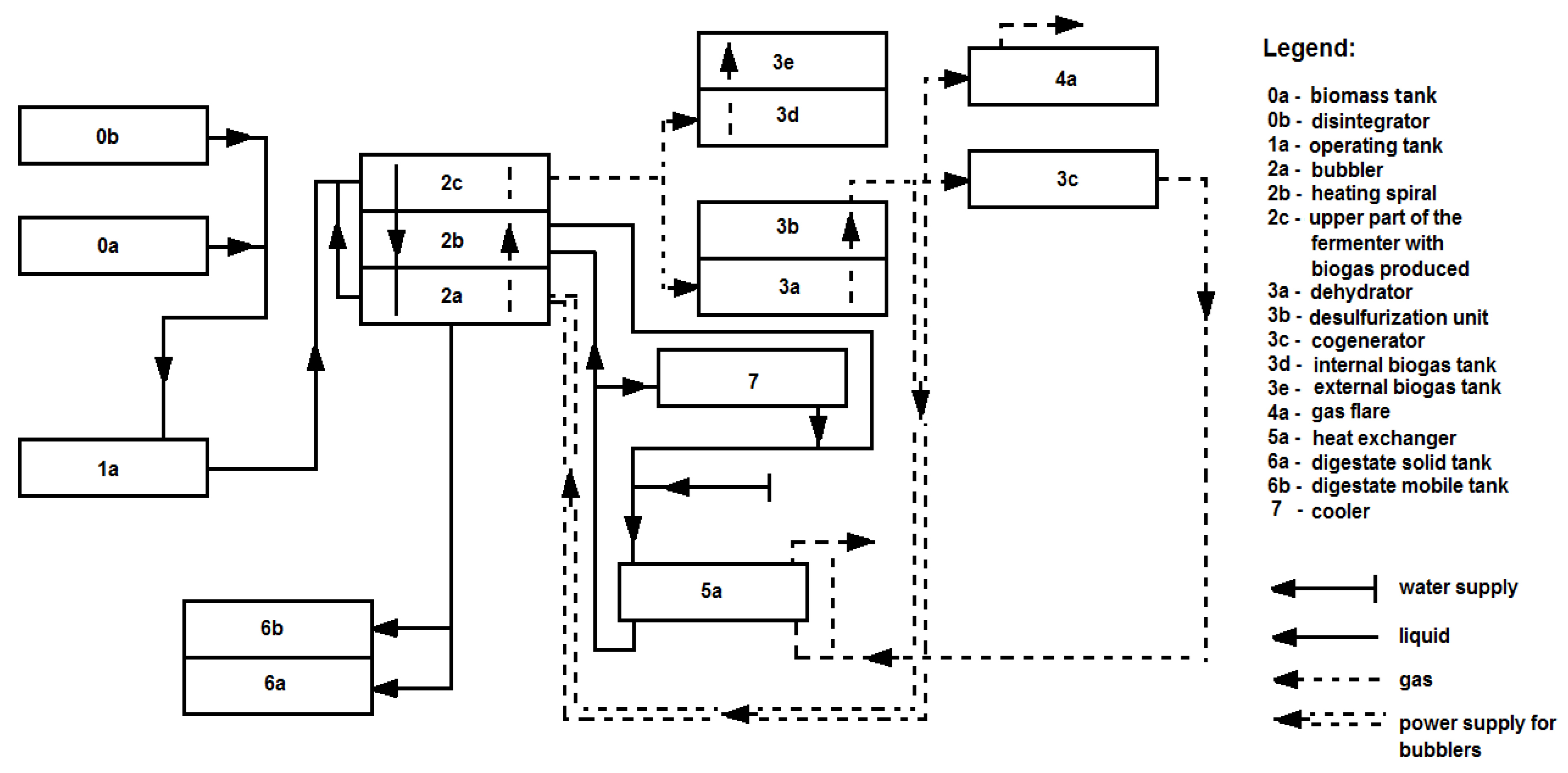
3.1. Agricultural Biogas Production Installation Using a Polydisperse Substrate (Pig Manure)-Research Position

A pilot biogas production Figure 2—described in detail by Klimek et al. [77]—using pig slurry was implemented [34] on a farm with 1100 Dan Bred pigs for fattening [78] kept in a grate system.
The production of substrate (pig slurry) is characterized by the way pigs are nourished—Table 3. The feed fed in the form of Superconcentrate 600 plus is a compound feed consisting of post-extract meal: soybean meal, rapeseed meal, calcium carbonate, phosphate, complementary herbal mixture for pigs over 30 kg with the addition of phytobiotic and acidifist—the content of analytical components in 1 kg [79].
In the Institute of Technology and Life Sciences, Division in Poznan, a pilot plant was developed, schematic diagram—Figure 3.
The method of pre-treatment of substrates, production of crude biogas, treatment of purified biogas and cogeneration for the proper operation of the fermenter and installation—described in detail in the work Klimek et al. [77]. However, when it comes to the purification of raw biogas obtained in the fermenter, an interesting use of two 3b desulfurizers, each with a capacity of 50 L, was indicated. Regeneration of the deposit involves the use of modification of turf ore and activated carbon. Crude biogas is directed alternately to one of the desulfurizations, where it is purified to remove sulfur compounds. During this time, the bed in the second desulfurizer is regenerated. Pzed desulfurization is installed from several dehydrators for crude biogas 3a. The overpressure of the biogas in the fermenter overcomes the flow resistance through the dewatering and desulfurization plant estimated at (2 ÷ 3) kPa. Desulfurized biogas is stored in a 3d tank under overpressure, which is equipped with a gas protection protecting the gas tank against exceeding the permissible overpressure.

3.2. Scope and Research Methodology

The experimental tests of the implemented installation concerned the evaluation production quality of desulphurized biogas.
Studies were carried out in the field of:
-
desulphurization of raw agricultural biogas using the granular bed adsorption-absorption technique.
The quality of the desulphurized biogas and the pressure drop during desulphurization were estimated.
The basis for the assessment of the production of crude biogas from the fermenter through the “gas path” to the desulfurizers in the pilot plant was the characteristics of the gas flow resulting from the pressure forcing this flow. In each case, the determination of this characteristic consisted in determining the effect of the biogas stream on the value of the overpressure corresponding to the pressure drop, which corresponded to the total resistance of the flow of raw biogas through the adhesive bed in the fermenter. The following algorithm was used in the conducted experimental studies:
-
Raw biogas was produced using an adhesive bed under mesophilic process conditions.
-
The criteria for the evaluation of biogas production were developed depending on:
-
the composition of crude and desulphurized gas in the flow in time;
-
gas temperature over time in the fermentor, before the desulfurizer, after the desulfurizer;
-
gas permeability in time in the fermenter (adhesive bed), before the desulphurizer, after the desulphurizer (loose bed).

4. Results and Discussion

Experimental studies were conducted on a measurement system to evaluate the quantity and quality of biogas under the conditions of raw biogas production process [80]. The raw biogas production node is a transport system of biogas produced in a fermentation tank together with equipment and enables to conduct, control and regulate the fermentation process (Figure 4). Control and measurement of biogas system—system operation description: the system is equipped (at the input) with gas meter and stationary raw gas analyzer QIR1 and control analyzer chemical composition of the desulphurized gas QIR2. The analyzer contains CH4, CO2, H2S and O2 measurement modules, and its indications can be checked on the display or used for: activate the “visual-audible” indicator or control the operation of the adsorption unit. This the biogas temperature is measured by the TT6 sensor. Raw biogas pressure increase it is released at a pressure of 35 mbar and directed to the desulfurizers.
The study was conducted to measure the raw biogas flow rate resulting from the reference pressure in the fermenter. An independent evaluation of the biogas volume and pressure drop in the adhesive backbone bed was performed.
The basis for evaluating the hydrodynamics of gas flow through the adhesive bed is the flow characteristic resulting from the pressure forcing this flow. In each case, the determination of this characteristic consists in determining the influence of the biogas stream on the value of this overpressure, equivalent to the pressure drop—this is equivalent to determining the total resistance to biogas flow through the adhesive bed. The basis for the evaluation of biogas production is the course of change for the average daily gas flux. It should be noted that after the 10th day there was a stabilization of biogas production, which lasted 4 days.
The polydisperse substrate from which agricultural biogas is produced depends on the feeding of the fattening pig. This translates into the quality of agricultural biogas, in which CH4 reaches up to 80%—Figure 5. It was observed that for optimal biogas production, mixing in the range of (1.5 ÷ 2.0) m3 of polydisperse substrate, which is natural pig manure, should be used.
To maintain the biogas production process, under the conditions of minimum replacement of 1.5 m3 of polydisperse substrate in 24 h for 15 m3 of fermentor volume—an increase in H2S formation was observed, which is shown in Figure 6.
Due to the excessive amount of H2S released, reaching over 3000 ppm, a proprietary desulfurization method was developed, classified as a physico-chemical method, used outside the fermentor—Figure 7.
A coal mixture (activated carbon) with turf ore (iron compounds) was developed, which allows for 100% desulfurization of raw agricultural biogas under process conditions for mesophilic fermentation—Figure 8.
Taking into account the temperature range (22.3 ÷ 26.6) °C for raw biogas—measuring point TT6, i.e., measurement before the desulphurizer, it is worth noting that the purified biogas is cooler by the order of 3 °C according to the measuring point TT7, i.e., measurement after desulphurizer temperature range (18.3 ÷ 23.6) °C.
An interesting fact is the observed phenomenon of low pressure (Figure 9) for the PT2 measuring point—measurement before the desulfurizer in the pressure range (0.61 ÷ 0.75) mbar.
Taking into account the pressure range (6.90 ÷ 19.78) mbar for raw biogas—measurement point PT1, i.e., measurement inside the fermentor, it is worth noting that the purified biogas has a lower pressure of 1 mbar according to the measurement point PT3, i.e., measurement after desulphurizer in the pressure range (5.90 ÷ 18.78) mbar.
By adsorption on an activated carbon bed, H2S is removed from biogas [81]. The method is commonly used to treat a wide range of pollutants from industrial exhaust air, such as volatile organic compounds (VOCs), and to remove H2S and odors from municipal sewer systems [82]. The treated gas can be pre-filtered, dried, or cooled to aid the adsorption process. Carbon is usually in the form of small granules or extruded pieces. A very high degree of adsorption can be achieved so that the treated exhaust air is essentially free of VOCs and/or H2S. Although the mechanisms are not yet well understood [83], it is generally accepted that contaminant removal occurs by both physical and chemical means. The most common use of adsorption on activated carbon is no carbon regeneration [81]. However, the cost of replacing activated carbon can be significant, so regenerable systems are used in which an activated carbon bed adsorbs contaminants while a reserve bed is regenerated by steam stripping [82]. The activated carbon bed can be regenerated continuously using atmospheric oxygen, leading to biological oxidation similar to the process described in [81]. Activated carbon can also be doped or impregnated with various compounds, such as potassium iodide, to increase the reaction rate by combining physical sorption pathways and chemical reactions [83,84,85]. Activated carbon treatment could potentially be used to “polish” the biogas quality after some pretreatment step. However, it is unlikely to be widely used as a single biogas treatment step in piggeries due to the high cost of batch replacement and complexity of regeneration options [86].
According to [87], adsorbents used in desulfurization are usually selected based on their adsorption capacity for H2S [88], adsorption process kinetics, durability reflected by mechanical properties, stability of chemical properties—H2S content in the gas can be reduced to low residual concentrations < 1 ppm [89]. Adsorption techniques result in high desulfurization efficiency, especially when using carbon adsorbents [42]: RGM1 activated carbon for which the adsorbed gas concentration is 27.15 mg∙g−1, and RBAA1 activated carbon for which the adsorbed gas concentration is 20.43 mg∙g−1. However, when using adsorbents, it is important to establish the maximum concentration of H2S at which the desulfurization process is profitable.
The methods using cheap bog ore [15]—the range of biogas desulphurization efficiency up to 90% [90] and the active modified coal [23]—the range of biogas desulphurization efficiency up to 95% [9] are also of significant economic importance.
In a study [91], the H2S removal efficiency was nearly 100% at all gas flow rates for allophane soil, brown soil and black sand, followed by typical sand (about 90–100%). This study showed that selected New Zealand soils with high iron content could potentially be used to build simple and inexpensive H2S adsorption beds to improve biogas quality. The H2S removal efficiency of the used soil materials can be enhanced by exposing them to the atmosphere.In the absorption process, several commercial carriers have been offered as improved alternatives to iron sponge for use in H2S removal in many industries [92]. Such commercial products have iron coatings on various support structures, such as dried manure, ceramic beads, diatomaceous earth, or unspecified proprietary materials [93], or consist of a granular iron oxide-rich substrate, such as red mud, which is a waste product from aluminum production [84]. At high H2S concentrations (1000 to 4000 ppm), 100 g of red mud pellets are expected to bind 50 g of sulfide; however, such pellets are likely to be more expensive than wood chips [94]. Long-term studies of H2S sorption from biogas carried out under the conditions of a selected sewage treatment plant allowed for the determination of a trend line describing the decrease in the effectiveness of its removal by the tested desulphurization mass as a function of time. The obtained dependence makes it possible to forecast the replacement time of the tested sorbent. The absorptive capacity of the tested sorbent, created on the basis of bog iron and alkaline activators, determined for average, year-round operating conditions of the sewage treatment plant, is 36% of the absorbency determined in laboratory conditions. This may result from the difficulty of maintaining optimal operating parameters of desulfurizers in real conditions, such as: pH, temperature and humidity. The time of bed depletion determined in real conditions is 52% of the time resulting from the stoichiometry of the chemical reaction (without taking into account the participation of activators). The experimentally obtained desulfurization mass consumption index is 0.0035 m3∙1000 m−3 of biogas (i.e., approximately 3.3 kg∙1000 m3), and the unit purchase costs of it are approximately PLN 9 1000 m−3. Purification of biogas with the use of the tested desulphurization mass allows to reduce the concentration of H2S below the required technical value of 200 mg∙m−3. The results confirmed that under the conditions of the studied sewage treatment plant it is sufficient to replace the deposit every six months [49].
Recirculation of biogas with hydrogen sulfide absorption has proven to be an effective method for reducing hydrogen sulfide content in biogas [95]. During recirculation, a reduction in hydrogen sulfide concentration was obtained, and the quality of biogas was improved. The highest methane content was 78.7% and 83%, respectively. Considering the hydrogen sulfide content, prolonged operation of recirculation led to high efficiency of its removal from biogas. When the recirculation was turned off, the hydrogen sulfide concentration in the biogas increased to 19,960 ppm. When biogas recirculation was turned off, the hydrogen sulfide concentration in the reactor increased to 4.18 mg∙L−1. When recirculation was restarted, a decrease in sulfide concentration was observed (0 mg∙L−1), suggesting that the inhibitory effect of sulfide is partially suppressed [95]. Taking into account the above-mentioned research together with the effects of the deposits used, the originality of the applied adsorption-absorption technique for the innovative deposit should be indicated.
The disadvantage of the proposed method may be the medium (bed) for the removal of hydrogen sulphide in the production of raw biogas in the process of anaerobic fermentation. The adsorption medium is regenerated or replaced with a new one—this is an important feature due to the arduous nature of the regeneration activities performed. Also, the use of activated carbon in a modification for a desulfurization bed can be an economic problem. The price, compared to other desulphurization beds available on the market, may be a drawback, but with the excellent effectiveness of H2S adsorption at the same time—the use time of the cogenerator should be longer, which will allow us to delay the replacement of the used cogenerator components.
On the basis of the conducted experimental studies, guidelines for future exploitation studies of the desulphurization and biogas treatment system were developed. The biogas purification-treatment system consists of a set of two desulphurizers and a biogas dehydrator with equipment for the regeneration of the bed. The produced biogas escapes from the upper space of the fermenter through a valve equipped with a manual ball valve or a valve equipped with a controlled ball valve. Then, the raw biogas flows to one of the two desulphurizers, where it is cleaned of sulfur compounds (mainly hydrogen sulphide and mercaptans—thiols). The desulphurization of biogas is carried out with the help of hydrated iron oxides contained in the ore. Sulfur compounds are oxidized to elemental sulfur, which is retained in the ore. The ferrous sulfide formed in the reaction is then regenerated back to iron II oxide with oxygen in the presence of water vapor. In order to provide the conditions for the regeneration of the catalyst in the turf ore, the mixture of water vapor generated in the generator with air should be introduced into the biogas by means of a compressor. The amounts of these substances must be selected on the basis of the stream of sulfur compounds carried by the biogas. The regeneration of the bed takes place after the loss of the biogas purification capacity from harmful admixtures is found. Depending on the quantity, type of adsorber used and the efficiency of the system, this takes place approximately once every~9 months and (in this case) this process is excluded from the automatic control cycle. Desulphurizers require, from time to time, decommissioning for discovery and mixing (regeneration by mixing with atmospheric air) or replacement of the ore with a new one. In order to carry out such an operation safely, for example, one desulphurizer should be cut off from the biogas installation with valves, and then nitrogen should be introduced from the cylinder, removing the biogas from the desulphurizer to the atmosphere through a suitable valve. After the regeneration or replacement of the bog iron, the desulphurizer can be put back into operation in the installation. In order for the regeneration of the bog ore to take place without downtime of the fermenter, the biogas plant is provided with two alternating desulfurizers. Too much air introduced into the biogas may result in the formation of an explosive mixture, while too much water vapor may obstruct the biogas, causing it to condense and accumulate in the tank. To remove excess moisture in the gas, install a gas dehydrator downstream of the desulphurisers. The biogas overpressure in the fermenter will allow to overcome the resistance of its flow through the desulfurizer and dehydrator and overcome the back pressure in the gas tank.

5. Conclusions

Polish agricultural producers, by restructuring their farms, not only increase their area, but also show openness to the introduction of energy-saving solutions related to renewable energy sources on farms and try to obtain funds for innovative investments that will reduce production costs, and can even be a source of additional income. However, currently Polish producers are forced to use foreign solutions, often expensive and not adapted to Polish agricultural conditions and the raw material base offered. Research on energy efficiency in farms has never been conducted comprehensively in the country, no attention has been paid to the creation of standardized, widely implemented and profitable technologies.
In many agricultural regions, the outdated infrastructure of energy systems and the lack of material resources for new investments cause a civilization and economic collapse in terms of Poland’s energy policy. Ensuring the supply of energy from agro-energy and utilization installations would reverse the negative processes, reduce negative social phenomena (impoverishment of the inhabitants, increase in unemployment, emigration) and enable sustainable development of local entrepreneurship, based on local natural resources and local renewable energy sources. Decisive and effective support for the development of renewable energy sources can be a way to bolster the budgets of farms and other entrepreneurs involved in energy production and the construction and operation of bio-agro-energy installations, especially for the purification of desulphurized biogas with the proposed original method. The increase in the use of renewable energies is very important, primarily due to the possibility of increasing the degree of independence from imported energy supplies, diversification of supply sources, as well as creating conditions for the development of distributed energy based on locally available raw materials. Renewable energy in Poland is of particular importance for the implementation of the goals of our country’s energy policy, which was reflected in one of the most important strategic documents, i.e.: “Poland’s Energy Policy until 2030”.
Intensive animal production is a source of difficult to utilize, incl. slurry, polluting the natural environment [96]. The technology of waste utilization by methane fermentation is an excellent way of neutralizing them while obtaining energy [97]. The production of biogas increases strongly in the world, which increases the importance of this fuel, where the methane content and the concentration of hydrogen sulphide are of particular importance. Hydrogen sulfide removal (desulfurization, desulfurization) is one of the most important processes in biogas treatment [30].
This problem was solved by the Institute of Technology and Life Sciences in Falenty, specifically by the Department of Renewable Energy in Poznań—a method for raw biogas desulphurization was developed along with the necessary infrastructure for this purpose. Agricultural biogas is produced in a monosubstrate reactor for methane fermentation of slurry [2]. A monosubstrate reactor was designed and constructed, a model of the biogas flow reactor was made based on the invention [98]. The biogas plant [34] was implemented at a farm in Ocieszyn as part of the project akr. BIOGAS&EE funded by the National Centre for Research and Development under the BIOSTRATEG 1 programme, directed by the Project Manager—Dr. Grzegorz Wałowski, Eng.
The paper presents preliminary results of experimental studies on agricultural biogas desulphurisation for an example of an average daily agricultural biogas production and the qualitative composition of agricultural biogas produced from pig slurry. The measurement results show a clear effect of raw biogas desulfurization for biogas flow assessment using the author’s adsorption-absorption technique in the context of agricultural biogas treatment. It has been shown that:
(1)
The applied technique of desulphurization of raw agricultural biogas significantly contributes to the treatment of purified biogas;
(2)
The method of using a granular bed in desulphurizers significantly improves the process of raw biogas desulphurization, for high-calorific biogas 100% desulphurized and in cogeneration into electricity and heat;
(3)
Raw biogas can be cleaned easily and reliably and produced close to the livestock building.

Author Contributions

Conceptualization, G.W. and A.S.; Data curation, J.S., K.B., A.K. and G.W.; Formal analysis, M.K., K.K., A.S., B.J. and G.W.; Funding acquisition, K.K., M.K. and G.W.; Investigation, B.J., D.A., B.D., A.K. and G.W.; Methodology, J.S., K.B., D.A., B.D., A.K. and G.W.; Project administration, G.W.; Resources, M.K., K.K., S.S., R.K. and G.W.; Software, J.S., K.B. and G.W.; Supervision, G.W.; Validation, J.S., K.B., S.S., R.K. and G.W.; Visualization, J.S., K.B., S.S., R.K. and G.W.; Roles/Writing—original draft, G.W.; Writing—review and editing, G.W. All authors have read and agreed to the published version of the manuscript.

Funding

The study conducted as part of the project financed by (1) National Center for Research and Development implemented under the BIOSTRATEG program, contract No. BIOSTRATEG1/269056/5/NCBR/2015; (2) The Research Task (statutory) No. 11/79/2019 “Developing a model describing the gas permeability of anisotropic porous materials in the aspect of adhesive hydrodynamics for agroenergetic applications” implemented by the Renewable Energy Department in the Poznan Branch, Institute of Technology and Life Sciences—National Research Institute, Falenty, and cooperation with the University of Life Sciences in Lublin, Lviv National Agrarian University, Jacob of Paradyz University in Gorzow Wielkopolski, Central Mining Institute and Poznan University of Technology. The APC was funded by University of Life Sciences in Lublin.

Institutional Review Board Statement

Not applicable.

Informed Consent Statement

Not applicable.

Data Availability Statement

The data presented in this study are available on request from the corresponding author.

Conflicts of Interest

The authors declare no conflict of interest. The funders had no role in the design of the study; in the collection, analyses, or interpretation of data; in the writing of the manuscript; or in the decision to publish the results.

References

  1. Smolinski, A.; Howaniec, N.; Gasior, R.; Polański, J.; Magdziarczyk, M. Thermal conversion of low rank coal, flotation concentrate and refuse derived fuel in the process of steam co-gasification to hydrogen-rich gas. Energy 2021, 235, 121348. [Google Scholar] [CrossRef]
  2. Wałowski, G.; Borek, K.; Romaniuk, W.; Wardal, W.J.; Borusiewicz, A. Modern systems of obtaining energy-biogas. In Monograph; Wacław, R., Ed.; Publishing House of the University of Agribusiness in Łomża: Warsaw, Poland, 2019; ISBN 978-83-947669-9-3. [Google Scholar]
  3. Aleksandrow, S.; Michalak, D. Analysis of the potential of the Łódź region in terms of building a biogas plant. Acta Innov. 2013, 7, 28–44. [Google Scholar]
  4. Kowalski, Ł.; Smerkowska, B. A Polish case study for biogas to biomethane upgrading. Combustion. Engines 2012, 1, 15–24. [Google Scholar]
  5. Piskowska-Wasiak, J. Treatment of biogas to the parameters of high-methane gas. Nafta-Gaz 2014, 70, 94–105. [Google Scholar]
  6. Kociołek-Balawejder, E.; Wilk, Ł. Review of methods for removing hydrogen sulphide from biogas. Przemysł Chem. 2011, 90, 389–397. [Google Scholar]
  7. Zawadzka, A.; Imbierowicz, M. Biogas, p. 17–31 and Technologies and devices for biogas plants, p. 153–168. In Collective Work Investing in Renewable Energy. Ecological, Technological, Financial and Benchmarking Aspects; Polish Academy of Sciences, Łódź Branch, Environmental Protection Commission, Pro-Akademia Association of Economic Advisors: Łódź, Poland, 2010; ISBN 978-83-86492-59-6. [Google Scholar]
  8. Wilk, J. Use of sewage sludge for biogas production. Aura 2011, 5, 18–20. [Google Scholar]
  9. Cebula, J. Selected Methods of Agricultural and Landfill Biogas Treatment; Publishing House of the Silesian University of Technology: Gliwice, Poland, 2012; ISBN 978-83-7335-983-3. [Google Scholar]
  10. Aleksandrow, S.; Staniszewska, M. The importance of renewable energy sources in the global economy and their impact on the labor market. Acta Innov. 2013, 6, 41–45. [Google Scholar]
  11. Wawer, P. 1.6 MW biogas plant. Ekologia Tech. 2013, 21, 204–209. [Google Scholar]
  12. Pomykała, R.; Łyko, P. Biogas from waste as biofuel for transport—Barriers and prospects. Chemik 2013, 5, 454–457. [Google Scholar]
  13. Zagdański, D. Implementation and operation of an agricultural biogas plant. An example of a selected object. Aura 2014, 6, 16–18. [Google Scholar]
  14. Gaj, K.; Cybulska-Szulc, H. Time changeability model of the bog ore sorption ability. Ecol. Chem. Eng. 2014, 21, 113–123. [Google Scholar] [CrossRef] [Green Version]
  15. Żarczyński, A.; Rosiak, K.; Anielak, P.; Wolf, W. Practical methods of purifying biogas from hydrogen sulphide. Part. 1. Application of solid sorbents. Acta Innov. 2014, 12, 24–35. Available online: http://www.proakademia.eu/gfx/baza_wiedzy/255/praktyczne_metody_oczyszczania_biogazu_z_siarkowodoru.pdf (accessed on 3 December 2015).
  16. Fischer, E.; Gattermann, H.; Grope, J.; Scholwin, F.; Weidele, T.; Weithäuser, M. Gasaufbereitung und Verwertungsmöglichkeiten. In Leitfaden Biogas von der Gewinnung zur Nutzung; Fachagentur Nachwachsende Rohstoffe e. V. (FNR): Gülzow, Germany, 2013; pp. 106–127. Available online: http://mediathek.fnr.de/media/downloadable/files/samples/l/e/leitfadenbiogas2013_web_komp.pdf (accessed on 3 December 2015).
  17. Rejman-Burzyńska, A.; Jędrysik, E.; Gądek, M. Concept of the plant for upgrading biogas to biomethane. Przemysł Chem. 2013, 92, 68–72. [Google Scholar]
  18. Michalska, K.; Kacprzak, A. Swedish model of development of innovative biogas technologies based on waste management. Acta Innov. 2012, 3, 39–70. [Google Scholar]
  19. Biernat, K.; Gis, W.; Grzelak, P.; Żółtowski, A. Possibilities of using biomethane as fuel for city buses on the example of Poland and Sweden. Przemysł Chem. 2013, 92, 1280–1284. [Google Scholar]
  20. Electrigaz Technologies Inc. Feasibility Study—Biogas Upgrading and Grid Injection in the Fraser Halley. British Columbia. Final Report. Available online: http://www.lifesciencesbc.ca/files/PDF/feasibility_study_biogas.pdf (accessed on 3 December 2015).
  21. Kogut, P.; Piekarski, J.; Dąbrowski, T.; Kaczmarek, F. Biogas production plants as a method of utilisation of sewage sludge in relation to the Polish legislation. Annu. Set Environ. Prot. 2012, 14, 299–313. [Google Scholar]
  22. Klemba, K. Biogas plant as a potential source of odor emissions and preventive measures. Eliksir 2015, 2, 22–27. Available online: http://chemia.p.lodz.pl/Eliksir/Eliksir_nr2.pdf (accessed on 3 December 2015).
  23. Żarczyński, A.; Rosiak, K.; Anielak, P.; Ziemiński, K.; Wolf, W. Practical methods of hydrogen sulphide removal from biogas. II. Application of sorption solutions and biological methods. Acta Innov. 2015, 15, 57–71. [Google Scholar]
  24. Vakili, M.; Gholami, Z.; Gholami, F. Removal of hydrogen sulfide from gaseous streams by a chemical method using ferric sulfate solution. World Appl. Sci. J. 2012, 19, 241–245. [Google Scholar]
  25. Kuo-Ling, H.; Wei-Chih, L.; Ying-Chien, C.; Yu-Pei, C.; Ching-Ping, T. Elimination of high concentration hydrogen sulfide and biogas purification by chemical–biological process. Chemosphere 2013, 92, 1396–1401. [Google Scholar]
  26. Zając, G.; Szyszlak-Bargłowicz, J.; Słowik, T. Production and use of biogas in the “Hajdów” sewage treatment plant. Gaz Woda Tech. Sanit. 2013, 2, 93–95. [Google Scholar]
  27. Zdeb, M. An Efficiency of H2S Removal from Biogas via Physicochemical and Biological Methods—A Case Study. Annu. Set Environ. Prot. 2013, 15, 551–563. [Google Scholar]
  28. Frare, L.M.; Bortoleto, R.M.; Mufalo, A.N., Jr.; Pereira, N.C.; Gimenes, M.L. Optimum liquid/gas ratio determination for removing H2S from biogas using Fe-EDTA solution. In Proceedings of the 4th Mercosur Congres on Process Systems Engineering: 2nd Mercosur Congres on Chemical Engineering, Costa Verde, Brasil; Available online: http://www.enpromer2005.eq.ufrj.br/nukleo/pdfs/0968_trabalho_968_revisado_final.pdf (accessed on 12 December 2015).
  29. Ermich, S.; Pruszyńska, E. Comprehensive biogas treatment—Biosulfex device: Operational results. Gaz, Woda Tech. Sanit. 2008, 4, 6–9. [Google Scholar]
  30. Paprota, E. Treatment of biogas as a way of its wider use. Autobusy. Tech. Eksploat. Syst. Transp. 2011, 10, 329–333. [Google Scholar]
  31. Steppa, M. Agricultural biogas plants. In Doc. dr inż. Wacław Romaniuk. Supplement and Update: Doc. dr inż.; Institute for Building Mechanization and Electrification of Agriculture, Department of Mechanization of Animal Breeding—Head of the Department, Wacław Romaniuk: Warsaw, Poland, 1992. [Google Scholar]
  32. Romaniuk, W.; Biskupska, K. An Agricultural Biogas Plant Step by Step; Hortpress: Warsaw, Poland, 2014; pp. 3–32. [Google Scholar]
  33. Aleszczyk, Ł. Biogas Desulphurization and Dewatering. Tank. Patent 230468, 25 June 2018. [Google Scholar]
  34. Agreement. Implementation Agreement No. AT-23/2019, ITP Falenty. 2019. Available online: https://res.mdpi.com/d_attachment/energies/energies-14-03538/article_deploy/energies-14-03538-v2.pdf (accessed on 1 April 2019).
  35. Pawłowska, M.; Zdeb, M. Comparison of the effectiveness of microbiological biogas desulphurization in bioscrubbers and biofilters with an irrigated layer. In Proceedings of the 3rd Congress of Environmental Engineering, Lublin, Poland, 13–17 September 2019; Volume 1, pp. 191–198. Available online: http://wis.pol.lublin.pl/kongres3/tom1/21.pdf (accessed on 3 December 2015).
  36. Biernat, K.; Samson-Bręk, I. Review of biogas purification technology to natural gas quality. Chemik 2011, 65, 435–444. [Google Scholar]
  37. Gaj, K.; Cybulska-Szulc, H.; Knop, F.; Steininger, M. Examination of biogas hydrogen sulphide sorption on a layer of activated bog ore. Environ. Prot. Eng. 2008, 4, 33–41. [Google Scholar]
  38. Cosoli, P.; Ferrone, M.; Pricl, S.; Fermeglia, M. Hydrogen sulphide removal from biogas by zeolite adsorption. Part I. GCMC molecular simulations. Chem. Eng. J. 2008, 145, 86–92. [Google Scholar] [CrossRef]
  39. Barbusiński, K. Calcium and magnesium peroxides—Application for commercial purposes and in environmental protection. Chemik 2006, 9, 433–438. [Google Scholar]
  40. Cebula, J.; Sołtys, J. Removal of Volatile Sulfur Compounds from Biogas Produced in an Agricultural Micro Biogas Plant with the Use of Halloysite Sorbent. Baltic Biogas Forum, Paper, September 2012. Available online: http://www.imp.gda.pl/BF2012/prezentacje/p254.pdf (accessed on 3 December 2015).
  41. Mroczkowski, P.; Seiffert, M. Purification and Injection of Biogas on the Example of Germany. Possibilities of Implementing Technology in Poland. The Material Was Created during the Scholarship of the Federal Environment Foundation (DBU) and the Foundation of Prof. Nowicki at the German Biomass Center (DBFZ). Available online: www.cire.pl (accessed on 3 December 2011).
  42. Kwaśny, J.; Balcerzak, W.; Rezka, P. Biogas and characteristics of selected methods of its desulphurization. J. Civil Eng. Environ. Archit. 2016, 63, 129–141. [Google Scholar]
  43. De Arespacochaga, N.; Valderrama, C.; Mesa, C.; Bouchy, L.; Cortina, J.L. Biogas deep clean-up based on adsorption technologies for Solid Oxide Fuel Cell applications. Chem. Eng. J. 2014, 255, 593–603. [Google Scholar] [CrossRef]
  44. Petersson, A. Biogas Cleaning in the Biogas Hand Book; Wellinger, A., Murphy, J.P., Baxter, D., Eds.; Woodhead Publishing Limited: Sawston, UK, 2013; ISBN 978-0-85709-498-8. [Google Scholar] [CrossRef]
  45. Hernández, S.P.; Scarpa, F.; Fino, D.; Conti, R. Biogas purification for MCFC application. Int. J. Hydrog. Energy 2011, 36, 8112–8118. [Google Scholar] [CrossRef]
  46. Micoli, L.; Bagnasco, G.; Turco, M. H2S removal from biogas for fuelling MCFCs: New adsorbing materials. Int. J. Hydrog. Energy 2014, 39, 1783–1787. [Google Scholar] [CrossRef]
  47. Sisani, E.; Cinti, G.; Discepoli, G.; Penchini, D.; Desideri, U.; Marmottini, F. Adsorptive removal of H2S in biogas conditions for high temperature fuel cell systems. Int. J. Hydrog. Energy 2014, 39, 21753–21766. [Google Scholar] [CrossRef]
  48. Herr, M.; Lermen, A.; Rostek, S. Biogaspartner—A joint initiative. Dtsch. Energ. Agent. GmbH HP Druck Berlin 2010, 5, 1–72. [Google Scholar]
  49. Cybulska, H.; Gaj, K.; Knop, F.; Steininger, M. Research on the Sorption of Hydrogen Sulphide Contained in Biogas on Activated Turf Ore; Institute of Environmental Protection Engineering, Wrocław University of Technology: Wrocław, Poland, 2021. [Google Scholar]
  50. Jędrczak, A. Biological Waste Treatment; PWN: Warsaw, Poland, 2007; pp. 186–190. ISBN 978-83-01-15166-9. [Google Scholar]
  51. Więckol-Ryk, A.; Krzemień, A.; Smoliński, A.; Lasheras, F.S. Influence of wet flue gas desulfurization on amine based absorption plant for CO2 removal. Sustainability 2018, 10, 923. [Google Scholar] [CrossRef] [Green Version]
  52. Krzemień, A.; Więckol-Ryk, A.; Smoliński, A.; Koteras, A.; Więcław-Solny, L. Assessing the risk of corrosion in amine-based CO2 Capture Process. J. Loss Prev. Process Ind. 2016, 43, 189–197. [Google Scholar] [CrossRef]
  53. Ramos, I.; Fdz-Polanco, M. Microaerobic control of biogas sulphide content during sewage sludge digestion by using biogas production and hydrogen sulphide concentration. Chem. Eng. J. 2014, 250, 303–311. [Google Scholar] [CrossRef]
  54. Nemati, M.; Harrison, S.T.L.; Hansford, G.S.; Webb, C. Biological oxidation of ferrous sulphate by Thiobacillus ferrooxidans: A review on the kinetic aspects. Biochem. Eng. J. 1998, 1, 171–190. [Google Scholar] [CrossRef]
  55. Ramos, I.; Pérez, R.; Reinoso, M.; Torio, R.; Fdz-Polanco, M. Microaerobic digestion of sewage sludge on an industrial-pilot scale: The efficiency of biogas desulphurisation under different configurations and the impact of O2 on the microbial communities. Bioresour. Technol. 2014, 164, 338–346. [Google Scholar] [CrossRef]
  56. Dudek, J.; Klimek, P.; Kołodziejak, G.; Niemczewska, J.; Zalewska-Bartosz, J. Technologies for Energetic Use of Landfill Gas. USA EPA, Oil and Gas Institute, Kraków. Available online: http://www.metmarkt.com/project/2/dws/out/LFG-podrecznik.pdf (accessed on 22 February 2021).
  57. Ryckebosch, E.; Drouillon, M.; Vervaeren, H. Techniques for transformation of biogas to biomethane. Biomass Bioenergy 2011, 35, 1633–1645. [Google Scholar] [CrossRef]
  58. Allegue, L.B.; Hinge, J. Biogas Upgrading Evaluation of Methods for H2S Removal; Danish Technology Institute: Taastrup, Denmark, 2014; pp. 1–31. Available online: https://www.teknologisk.dk/_/media/60599_Biogas%20upgrading.%20Evaluation%20of%20methods%20for%20H2S%20removal.pdf (accessed on 17 September 2021).
  59. Kujawski, J. Kujawski, O. Overview of biogas production technology (part three). Czysta Energ. Abrys 2010, 2, 28–30. [Google Scholar]
  60. Gattermann, H.; Kaltschmitt, M.; Niebaum, A.; Schattauer, A.; Scholwin, F.; Weiland, P. Produkcja i Wykorzystanie Biogazu. Institut für Energetik und Umwelt GmbH. Available online: http://www.ieo.pl/pl/aktualnosci/183-produkcjabiogazu.html (accessed on 10 December 2014).
  61. Cebula, J. Biogaz purification by sorption techniques. Archit. Civil. Eng. Environ. 2009, 2, 95–103. [Google Scholar]
  62. Brudniak, A.; Dębowski, M.; Zieliński, M. Purification and enrichment of biogas in ash-water suspension. Ecol. Eng. 2013, 32, 7–16. [Google Scholar]
  63. Wałowski, G. Hydrodynamics of the biogas production process in a skeletal fermentation reactor. In Wacława Romaniuk: Innovative Technologies in Animal Production Taking into Account the Standards of the European Union, Environmental Protection and Renewable Energy; ITP Publishing House: Warsaw, Poland, 2018; pp. 199–209. ISBN 978-83-65426-34-5. [Google Scholar]
  64. Romaniuk, W.; Głaszczka, A.; Biskupska, K. Analysis of biogas installation solutions for family and farm farms. In Engineering in Agriculture; Monographs No. 9; ITP Publishing House: Warsaw, Poland, 2012. [Google Scholar]
  65. Staszewski, R.; Wagner-Staszewska, T. The Adsorbent Regeneration System in the Adsorption-Desorption Installation. Poland Patent Application P.165947, 9 December 1991. [Google Scholar]
  66. Hobler, A.; Stumpf, W.; Quasnitschka, H.; Kriebel, M. Method and Installation for the Treatment of Nitrogen-Containing Natural Gas. Poland Patent Application P.182645, 14 October 1996. [Google Scholar]
  67. Kumanowski, K.S.; Szewczyk, K.W.; Zamojska, A.M.; Kumanowska, E.J. The Method of Utilizing Liquid Manure by Methane Fermentation and the Installation for Utilizing Liquid Manure by Methane Fermentation. Poland Patent Application P.386459, 6 November 2008. [Google Scholar]
  68. Filanowski, P.; Pituła, M.; Rybicki, C. Biogas Purification Method for Transmission Gas Parameters and Biogas Purification Installation. Poland Patent Application P.403141, 13 March 2013. [Google Scholar]
  69. Urych, B.; Smoliński, A. Sewage sludge and phytomass co-pyrolysis and the gasification of its chars: A kinetics and reaction mechanism study. Fuel 2021, 285, 119186. [Google Scholar] [CrossRef]
  70. Smoliński, A.; Howaniec, N.; Bąk, A. Utilization of energy crops and sewage sludge in the process of co-gasification for sustainable hydrogen production. Energies 2018, 11, 809. [Google Scholar] [CrossRef] [Green Version]
  71. Smoliński, A.; Howaniec, N. Co-gasification of coal/sewage sludge blends to hydrogen-rich gas with the application of the simulated high temperature reactor excess heat. Int. J. Hydrog. Energy 2016, 41, 8154–8158. [Google Scholar] [CrossRef]
  72. Urych, B.; Smoliński, A. Kinetics of Sewage Sludge Pyrolysis and Air Gasification of Its Chars. Energy Fuels 2016, 30, 4869–4878. [Google Scholar] [CrossRef]
  73. Marek, P. The amount of manure produced in pig production and the related potential of biogas production in Poland in 2018, broken down by municipalities. In Information Catalog. Developed as Part of: The Implementation of the Multiannual Program for 2016–2020 Entitled “Technological and Natural Projects for Innovative, Effective and Low-Emission Economy in Rural Areas”; Specified in the Contract No. GZ.me.032.1.9.2018 Concluded on 17 April 2018 between the Minister of Agriculture and Rural Development and the Institute of Technology and Life Sciences in Falenty;Unpublished Work.
  74. Decewicz, P. Spatial Model Based on Data from the Institute of Technology and Life Sciences in Falenty. Developed as Part of: The Implementation of the Multiannual Program for 2016–2020 Entitled "Technological and Natural Projects for Innovative, Effective and Low-Emission Economy in Rural Areas"; Specified in the Contract no. GZ.me.032.1.9.2018 Concluded on 17 April 2018 between the Minister of Agriculture and Rural Development and the Institute of Technology and Life Sciences in Falenty; Unpublished Work.
  75. Curkowski, A.; Onkisz-Popławska, A.; Mroczkowski, P.; Zowski, M.; Wiśniewski, G. A Guide for Investors Interested in Building Agricultural Biogas Plants; The Work Was Commis-Sioned by the Ministry of Economy at the Institute for Renewable Energy; Instytut Energetyki Odnawialnej: Warszawa, Poland, 2011; p. 126. [Google Scholar]
  76. Wałowski, G. Development of biogas and biorafinery systems in Polish rural communities. J. Water Land Dev. 2021, 49, 156–168. [Google Scholar] [CrossRef]
  77. Klimek, K.; Kapłan, M.; Syrotyuk, S.; Konieczny, R.; Anders, D.; Dybek, B.; Karwacka, A.; Wałowski, G. Production of Agricultural Biogas with the Use of a Hydrodynamic Mixing System of a Polydisperse Substrate in a Reactor with an Adhesive Bed. Energies 2021, 14, 3538. [Google Scholar] [CrossRef]
  78. Danbred Genes for Global Pig Production. Available online: www.danbred.com (accessed on 20 May 2021).
  79. Tuczniki. Available online: http://neorol.eu/tuczniki/html (accessed on 20 May 2021).
  80. Wałowski, G. Multi-phase flow assessment for the fermentation process in mono-substrate reactor with skeleton bed. J. Water Land Dev. 2019, 42, 150–156. [Google Scholar] [CrossRef] [Green Version]
  81. Hagen, M.; Polman, E.; Jensen, J.; Myken, A.; Jönsson, O.; Dahl, A. Adding Gas from Biomass to the Gas Grid; Final Report 2001, Contract No: XVII/4.1030/Z/99-412. Available online: http://www.dgc.eu/pdf/altener.pdf (accessed on 17 September 2021).
  82. Total Air Pollution Control. Website: Gas Scrubbing—Activated Carbon Adsorbers. Available online: https://tapc.com.au/our-products/dry-scrubbers/ (accessed on 17 September 2021).
  83. Siefers, A.M. A Novel and Cost-Effective Hydrogen Sulfide Removal Technology Using Tire Derived Rubber Particles. Ph.D. Thesis, Iowa State University, Ames, IA, USA, 2010; p. 11281. [Google Scholar]
  84. Wellinger, A.; Linberg, A. Biogas Upgrading and Utilization—IEA Bioenergy Task 24: Energy from Biological Conversion of Organic Wastes; International Energy Association: Paris, France, 2005; Available online: http://www.iea-biogas.net/_download/publi-task37/Biogas%20upgrading.pdf (accessed on 17 September 2021).
  85. Abatzoglou, N.; Boivin, S. A review of biogas purification processes. Biofuels Bioprod. Bioref. 2009, 3, 42–71. [Google Scholar] [CrossRef]
  86. Skerman, A.G. Practical Options for Cleaning Biogas Prior to on-Farm Use at Piggeries; A Thesis Submitted in School of Chemical Engineering, Engineering Work; The University of Queensland: Brisbane, Australia, 2016. [Google Scholar]
  87. Pourzolfaghar, H.; Ismail, M.; Izhar, S.; MagharehEsfahan, Z. Review of H2S Sorbents at Low-Temperature Desulfurization of Biogas. Int. J. Chem. Environ. Eng. 2004, 5, 22–28. [Google Scholar]
  88. Okoro, O.V.; Sun, Z. Desulphurisation of Biogas: A Systematic Qualitative and Economic-Based Quantitative Review of Alternative Strategies. ChemEngineering 2019, 3, 76. [Google Scholar] [CrossRef] [Green Version]
  89. TVT. Biogas to Biomethane Technology Review; Vienna University of Technology: Vienna, Austria, 2012. [Google Scholar]
  90. Huynh, Q.; Thieu, V.Q.Q.; Dinh, T.P.; Akiyoshi, S. Removal of hydrogen sulfide (H2S) from biogas by adsorption method. In Proceedings of the 8th Biomas, Asia Workshop, Hanoi, Vietnam, 2 November–1 December 2011; Available online: http://www.biomass-asia-workshop.jp/biomassws/08workshop/files/20Fulltext%20-%20H2S.pdf (accessed on 17 September 2021).
  91. Pham, C.H.; Saggar, S.; Berben, P.; Palmada, T.; Ross, C. Removing Hydrogen Sulphide Contamination in Biogas Produced from Animal Wastes. In Farm Environmental Planning—Science, Policy and Practice; Occasional Report No. 31; Currie, L.D., Christensen, L.C., Eds.; Fertilizer and Lime Research Centre, Massey University: Palmerston North, New Zealand, 2018; 10p, Available online: http://flrc.massey.ac.nz/publications.html (accessed on 17 September 2021).
  92. Zicari, S.M. Removal of Hydrogen Sulphide from Biogas Using Cow-Manure Compost. Master’s Thesis, Cornell University in Partial Fulfilment, Ithaca, NY, USA. Available online: http://www.green-trust.org/ (accessed on 20 May 2021).
  93. Cherosky, P.; Li, Y. Hydrogen sulfide removal from biogas by bio-based iron sponge. Biosyst. Eng. 2013, 114, 55–59. [Google Scholar] [CrossRef]
  94. Krich, K.; Augenstein, D.; Batmale, J.P.; Benemann, J.; Rutledge, B.; Salour, D. Biomethane from Dairy Waste—A Sourcebook for the Production and Use of Renewable Natural Gas in California, Prepared for Western United Dairymen, Funded in Part through USDA Rural Development. 2005. Available online: http://www.calstart.org/Libraries/Publications/Biomethane_from_Dairy_Waste_Full_Report.sflb.ashx (accessed on 20 May 2021).
  95. Gróf, N.; Barbušová, J.; Hencelová, K.; Hutňan, M. Absorption removal of hydrogen sulfide from recirculated biogas. Acta Chim. Slovaca 2020, 13, 13–18. [Google Scholar] [CrossRef]
  96. Kupryś-Caruk, M. The agri-food industry as a source of substrates for biogas production. Adv. Sci. Technol. Agric. Food Ind. 2017, 2, 69–85. [Google Scholar]
  97. Marszałek, M.; Banach, M.; Kowalski, Z. Manure utilization by methane and aerobic fermentation—Biogas and compost production. Tech. J. 2011, 10, 143–158. [Google Scholar]
  98. Myczko, A.; Myczko, R.; Szulc, R.; Tupalski, L. Reactor for Methane Slurry. Fermentation. Patent Application P.220074, 4 July 2012. [Google Scholar]
Figure 1. The potential of biogas production in Poland for poviats; source: [74].
Energies 14 05929 g001
Figure 2. Pilot biogas production—view, from the right: a container with, among others, desulfurizers; fermenter; livestock building (pigsty); lagoon (reservoir for reacted ferment) [photo by Grzegorz Wałowski].
Energies 14 05929 g002
Figure 3. Diagram of a test bench for the production and purification of raw agricultural biogas [own elaboration].
Energies 14 05929 g003
Figure 4. Synoptic table for control system, raw biogas production and desulphurized biogas treatment; detailed description in Walowski’s work [76].
Energies 14 05929 g004
Figure 5. Percentage of agricultural biogas produced from polydisperse substrate [own elaboration]—volume of CH4, CO2, O2.
Energies 14 05929 g005
Figure 6. The amount of H2S in agricultural biogas produced from a polydisperse substrate [own elaboration]: H2S (raw)—for raw biogas; H2S (des)—for desulphurized biogas.
Energies 14 05929 g006
Figure 7. Desulphurizer—interior, volume of 50 L [photo by Grzegorz Wałowski].
Energies 14 05929 g007
Figure 8. Temperature measurement—measurement points in accordance with the process diagram (Figure 4)—necessary for the production and desulphurization of agricultural biogas produced from a polydisperse substrate [own elaboration]: TT3—measurement inside the fermentor; TT6—measurement before desulphurizer; TT7—measurement after desulfurizer.
Energies 14 05929 g008
Figure 9. Pressure measurement—measuring points according to the process diagram (Figure 4)—necessary for the production and desulphurization of agricultural biogas produced from a polydisperse substrate [own elaboration]: PT1—measurement inside the fermentor; PT2—measurement before desulfurizer; PT7—measurement after desulphurizer.
Energies 14 05929 g009
Table 1. Biogas desulphurisation methods [own elaboration].
MethodProcess or TechniqueApplicationRange of Biogas Desulphurisation Efficiency
PhysicalAbsorption (wet)
-
scrubbing water—differences in solubility of CO2 and CH4 in polar solvents are used;
-
absorbent:
(a)
methanol (Rctisol),
(b)
poly(ethylene glycol) dimethyl ether (Selexol, Genosorb),
(c)
propylene carbonate (Fluor),
(d)
sulfolane (Sulfinol).
>94% [5,12]
Absorption (dry)
-
adsorbent:
(a)
carbon (activated carbon),
(b)
mineral,
(c)
mineral and carbon.
up to 95% [9,15]
Absorption (wet)
-
dissolution of H2S in water or organic solvents:
(a)
Genosorb,
(b)
Rectisol,
(c)
Ifpex.
>96% [5,12]
Cryogenic separation
-
very low temperatures down to −100 °C and high pressure of about 40 bar
up to 99% [36]
ChemicalAbsorption
-
iron compounds:
(a)
bog iron ore (porous sedimentary rock).
up to 90% [6,9,14,15,37]
Membrane (porous or diffusive)
-
chemical potential of solutions or mixtures.
up to 99% [15,38]
Absorption (wet)
-
caustic soda solution;
-
aqueous alkanolamine solutions;
-
ferrous chloride solution.
(95 ÷ 99)% [10,39]
BiologicalOxidation
-
supplying air to biogas.
over 95% [6,15]
Microbiological reaction
-
bacteria of the family Thiobacillus producing elemental sulphur.
(80 ÷ 99)% [40]
Table 2. Desulphurisation methods, especially for agricultural biogas due to the fermentation process.
DesulphurisationCourse of ProcessApplicationRange of Biogas Desulphurisation Efficiency
chemicalin fermenter
-
chemical compounds, i.e., iron (III) and (II) chlorides;
-
sodium hydroxide;
-
iron hydroxide [59].
(80 ÷ 99)% [40]
outside fermenter
-
lye (usually sodium hydroxide) [60].
up to 94% [6]
biologicalin fermenter
-
in the presence of oxygen (which is supplied to the fermenter by blowing air through, for example, a small compressor) and Sulfobacter oxydans [60].
(80 ÷ 99)% [40]
outside fermenter
-
bioscrubbers;
-
biofilters;
-
biofilters with an irrigation layer.
(70 ÷ 98)% [61]
up to 95% [62]
up to 95% [62]
Table 3. Quantitative statement of the natural producer of slurry related to the time cycle [own elaboration].
Fattening PigVolume of SubstrateCycle
quantity time
35001400 m31 year
10.4 m390 days
10.4 L1 day
Publisher’s Note: MDPI stays neutral with regard to jurisdictional claims in published maps and institutional affiliations.

