1. Introduction
Small wind turbines (usually with a nominal output power less than 10 kW) are widely implemented in home-based renewable energy systems, smart road signs, water pumping on farms, and stand-alone measuring equipment. The power converter, which is an integral part of the wind turbine system, affects its cost, reliability, and efficiency. Different kinds of AC/DC power converters have been designed to work with PM generators, some of which enable a bi-directional power flow and others that make sensor-less operations possible. Sensor-less control of the PM generator directly reduces the cost of the electric machine and, finally, the total cost of the wind power plant.
In the scientific literature, there are many sources describing converters dedicated to small wind turbines (WTG). Most of them present diode boost converters with inductance in the DC circuit (
Figure 1). This is due to its simple design, high reliability, and low construction cost. Many authors have presented simplified mathematical models and results of simulation studies of a classical converter. Some papers [
1,
2] focus on a method allowing for maximum power tracking in variable rotational speeds of the wind turbine. The simulation results for a 3000 W small-scale wind generator based on a maximum power point tracking control have been presented [
3]. Article [
4] presents a multiport DC/DC converter allowing for the cooperation of various renewable energy sources with a DC/DC inverter—through the joint complementary operation of multiple renewable sources on the power grid. By combining various renewable energy sources, it is possible to stabilize the output of the system regardless of the time of day or weather conditions. The authors of [
5] present a feed-forward technique for the control of the DC/DC converter, enabling the effective operation of a wind generator in a broader range of turbine rotational speeds. Article [
6] presents a modular control strategy for a grid-connected, high power wind generation system without any information about the wind speed and rotational speed of the turbine. An algorithm for the efficient optimization of the boost converter in a wind turbine by adjusting the optimum working speed of the turbine is presented in [
7]. By using additional LC elements (elements of the resonant tank circuit in the classic converter), the voltage time rise in the transistor and the THD value of the generator current can be reduced; still, the converter must operate in DCM mode [
8]. Paper [
9] presents the problem of controlling converter cooperation with a single-phase inverter working on a rigid low-voltage network. Cooperation with the rigid network is also discussed in papers [
10,
11]; however, the classic solution is replaced by a two-leg three-phase PWM converter combined with a two-level capacitive voltage divider and half-bridge single-phase DC/AC inverter. Simulation-based comparative analysis of the efficiencies and loss balances for the buck−boost converter, boost converter, and three-phase converter is presented in [
12]. It has been shown that a classical boost converter achieves a very high efficiency of 95%—not differing from other converters. This is due to the high rated voltage of the generator (200 V) used for the simulation study. A novel maximum power tracking strategy for wind turbine systems based on a hybrid wind velocity forecasting algorithm is presented in [
13]. This algorithm uses deep self-learning mechanisms to compensate for the slow response of the anemometers and sensors, allowing the maximum power tracking of the generator to be reached more quickly. Recent scientific studies on improving the efficiency of boost converters with inductance in DC circuits cooperating with small-scale wind generators are focused on using the fuzzy logic technique. This allows for reducing oscillations of wind turbine output power, which occurs near the operating point [
14].
Diode boost converter with inductance in the AC circuit is a development of the classical converter concept with inductance in the DC circuit. Compared with the classic converter, this reduces the THD coefficient of the generator current; additionally, the efficiency of the wind generator and the converter can be significantly increased [
15]. Article [
16] presents simulation studies for a multi-port single-stage power converter enabling cooperation of the wind generator and diode boost converter with inductance in the AC circuit with a battery set. However, the main application area for this type of converter is the controlled DC voltage sources (PS)—through the low-voltage AC networks that power these converters. Inductance on the AC side of the converter allows for improving the power factor [
17,
18]. A space vector-based analytical analysis of the input current distortion of a three-phase discontinuous-mode boost rectifier system is reported in [
19]. In [
20], the authors propose a control method strategy for efficient switching of cycles in a converter (working in DCM mode) to reduce both the peak and RMS currents values of the main power components and the output voltage ripples. Article [
21] proposes a control method for the diode boost converter with inductance in an AC circuit, allowing for variable switching frequency operation without any current measurement. The simulation and experimental results are presented. Paper [
22] proposes (in addition to improving the power factor) a way to reduce the power losses in the switched transistor. These losses can be significantly reduced by attaching LC resonant tank elements without an additional switch in the SEPIC or Cuk type converters.
Another type of converter is the fully controlled six transistor bridges (Full Bridge). Unlike diode boost converters with inductance in the DC circuit, which operate only at the regenerative braking stage, they allow for four-quadrant operation of the three-phase brushless DC motors—this is very important for electric vehicle applications (EV) [
23,
24]. These converters can also be controlled (using different control algorithms) for the generator operation state (for electric vehicles, this is called regenerative braking) [
25,
26] in low-power wind turbines applications. The principle of operation of such converters (analogous to the DC/DC boost converter) is based on obtaining two operating states: energy storage in the electromagnetic circuit of the machine and returning the stored energy to the battery. The accumulation of energy in the electromagnetic circuit of the machine is realized by connecting together those phases of the motor that have the highest instantaneous phase voltage difference for a given angular position of the rotor. When transistors are switched off, the accumulated energy is transferred to the battery via anti-parallel diodes. Article [
27] presents methods of designing bridge converters, enabling two operation modes: the maximum output power tracking mode and the fixed output power mode of the wind turbines connected to the power system. A converter that performs functions of a load leveler, load balancer, harmonic compensator, and voltage and frequency controller for a stand-alone wind generator is presented at [
28]. A unique feature of the full transistor bridges (relative to other converts) is the ability to achieve synchronous transistor conduction at the regenerative braking stage. This increases the efficiency of the converter, which is particularly desirable for electromobility applications. When the converter is used with wind generators, whose rated voltages are several hundreds of volts, the increase in efficiency resulting from the synchronous conduction is negligible. The situation changes radically when a generator with a low voltage rating is used. Furthermore, full transistor bridges require complex control structures and motor shaft position detection, causing deterioration of their reliability and increasing the costs of converter construction—these features are especially desirable in the case of wind turbines.
Converters with a reduced number of switched transistors meet these requirements. This group includes a converter with three-switched transistors (Three-Switch). It enables regenerative braking using sensor and sensor-less control methods. Sensor control methods (shaft position detection is obtained from Hall sensors) are often presented in the literature in the context of electrically driven vehicles [
29,
30]. In [
31], a sensor-less control method using zero-crossing detection of the back electromotive force (EMF) is presented. A wide range of potential applications for this type of converter (EV and WTG) due to its high efficiency and reliability have been indicated. As mentioned above, the converter with three-switched transistors can also operate without any shaft position information [
32,
33]. In this case, the generator operation state is obtained by simultaneously switching the three transistors of the bridge, independently of the generator shaft position. This markedly simplifies the control system, reduces construction costs, and significantly improves the reliability of this type of converter—therefore, it is an interesting alternative to the commonly used diode boost converter with inductance in the DC circuit in low-power wind turbines. The analogous principle of operation as the converter with three-switched transistors (operating without any shaft position information) is characterized by a converter with additional two-way transistor switches. In this case, the generator operation state is achieved by simultaneously switching four transistor switches. Using additional two-way transistor switches also allows for easy adaptation of an existing non-controlled six-pulse diode rectifier to fully controllable regenerative braking operation.
A converter with two-switched transistors (Two-Switch) is also in the group of converters with a reduced number of switched transistors. This converter has the lowest number of transistors compared with the other bridge converters. It also enables sensor and sensor-less operation—like the three-switch converter. Taking into account the low cost of the converter and its high efficiency, it is a potentially attractive solution, especially for low voltage wind generators with sensor control [
34]. The sensor-less operation of the converter is possible for fill factors in the range of 0–50% [
35]. This limitation results in a lower power output from the generator. However, higher efficiencies can be achieved (in relation to sensor operation) due to the lower power losses resulting from the partial synchronous conduction of the power MOSFET transistors.
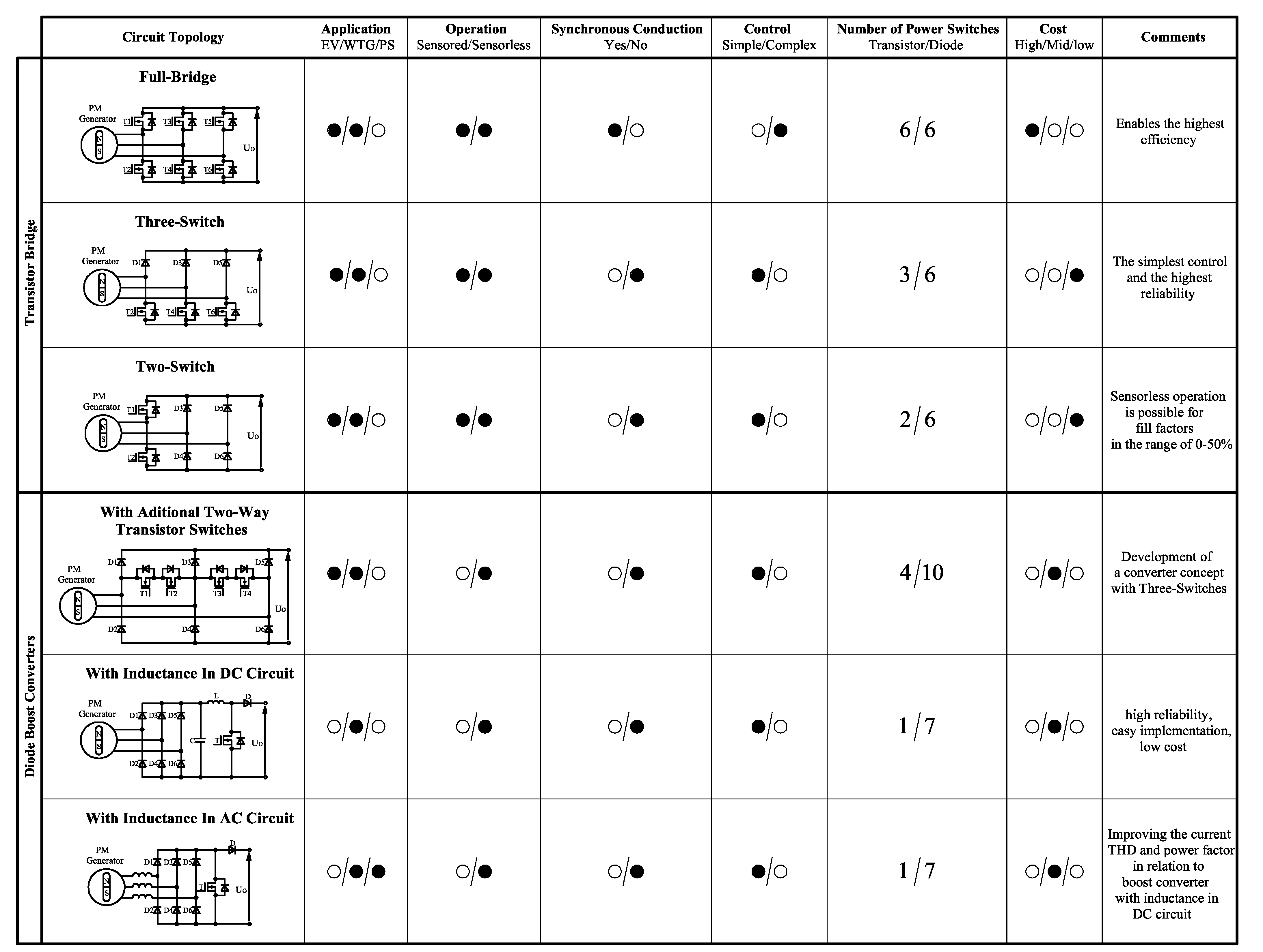
The classification of the AC/DC power converters used to operate PM generators is shown in
Figure 1.
The main factors affecting the cost of manufacturing a converter are the total number of switches and the complexity of the control system. The ability to use synchronous conduction of the power MOSFET transistors significantly improves the efficiency of the converter.
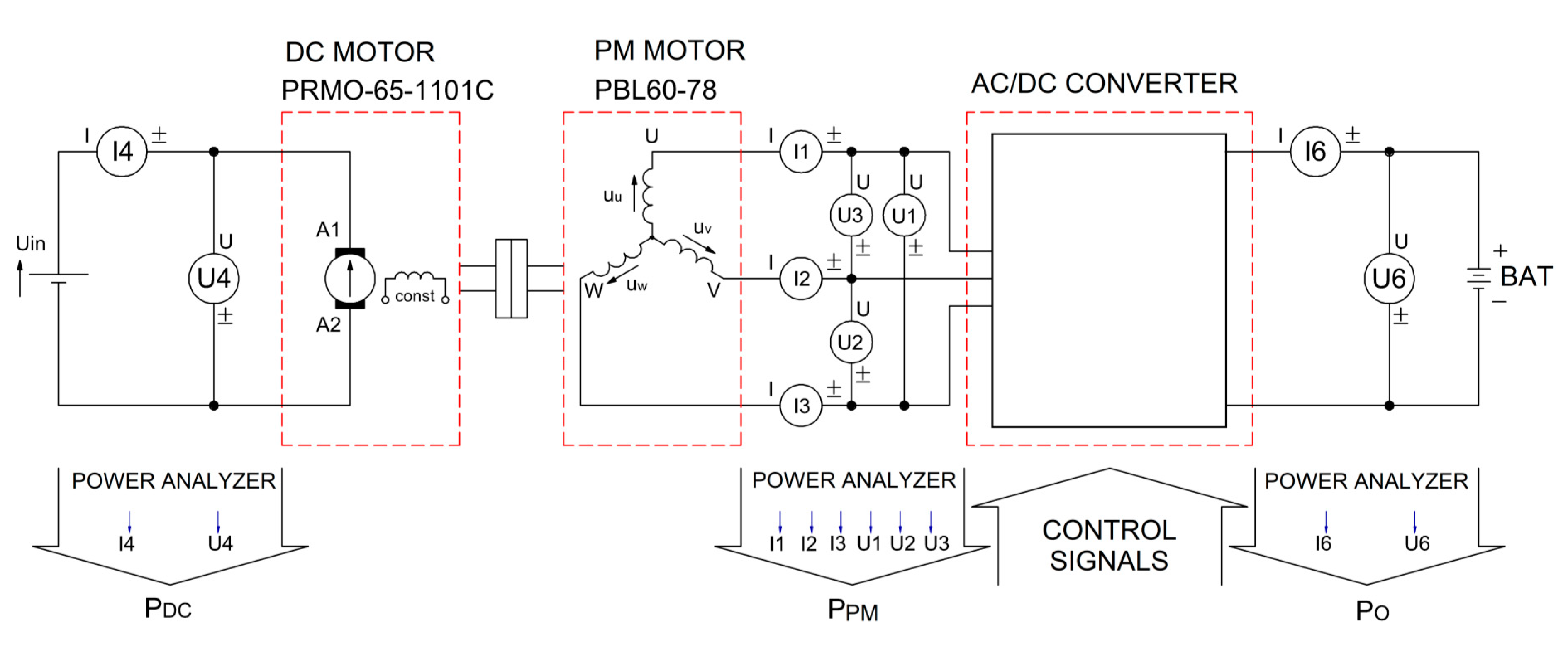
2. Methodology
The main goal of the study is to select a converter designed to work with a PM generator, with the following features: low construction cost, high efficiency, high reliability, and simple design and control. Based on an analysis of a number of converters, the investigation area was narrowed down to those that best met the requirements. Preliminary simulation studies of selected converters determined their basic characteristics, including efficiency. TCad software was used to conduct simulation studies. Thanks to the extended possibilities of recording the instantaneous power losses of the switches, the efficiency of the converter as a function of the load current was estimated. Parvalux PBL-60-78 motor with a rated power of 46 W and nominal DC bus voltage 24 V was used in the experimental test rig. A Yokogawa WT1600 precision power analyzer was used to measure the efficiency of the converters. Simulation and experimental studies were performed for several different machine rotational speeds with varying load currents. After the simulation studies, two converters were qualified for the final experimental tests. The efficiency and output power of the converter as a function of the generator rms current were determined. The experimental and simulation results were compared. An evaluation of the models used in the simulation studies was made. Finally, converters were compared in terms of efficiency, control range, control methods, and manufacturing costs. Potential areas of application for the selected converters were determined.
In the analyzed literature, there is no comparison presenting simulation and experimental studies of a range of converters for small wind turbines. Test results for individual converters are mainly presented. Admittedly, in [
12], three types of converters are compared, but only simulation-wise and for a relatively large generator output voltage of 200 V. Based on the literature review, the following converters were selected for further simulation studies: diode boost rectifier with inductance in DC circuit, and three-switch and two-switch converters. All are distinguished by a small number of power switches, have a simple control algorithm, and can achieve an efficiency of about 90%. In small wind turbines, diode boost rectifier with an inductance in DC circuit is most commonly used. The three-switch converter is not widely used, especially with sensor-less control. The two-switch converter is a recently developed and not well-known solution.
This paper presents, for the first time, comprehensive results of the simulation and experimental investigations of the two-switch converter in relation to two other solutions. This may determine its applicability to small wind turbines. For this reason, it received a little more attention.
3. Two-Switch Converter
The two-switch converter (called also one-branch controlled converter) can be controlled either in a sensor or sensor-less manner. The operating principle of the sensor control is shown in [
35], where the duty cycle of the complementary PWM waveform reached almost 100%. Sensor-less control is possible if the duty cycle for each transistor is less then 50% and the gate signals are mutually shifted by half a period.
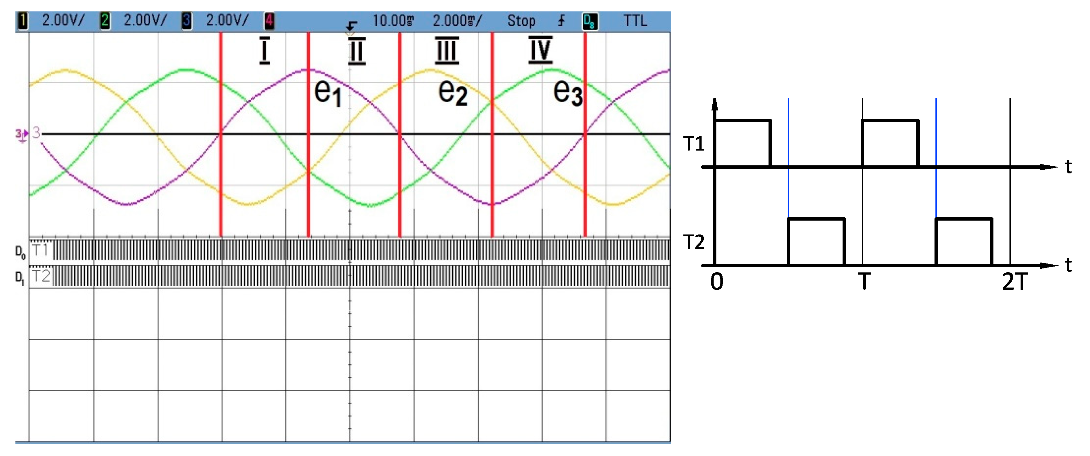
Figure 2 shows the three-phase back-EMF voltages generated by a PM generator and the control signals. For the full period of the voltages of 0–2π, four conduction sectors could be selected. Conduction sequences for all of the sectors are shown in
Table 1.
In each sector, two working stages can be distinguished. In the first stage, the current in two generator phases increased under the influence of the back-EMF voltages (state of two-phase dynamic braking). In the second state, the current from the PM rotor circuit flowed through the diodes to the battery (the state of energy recovery to the battery).
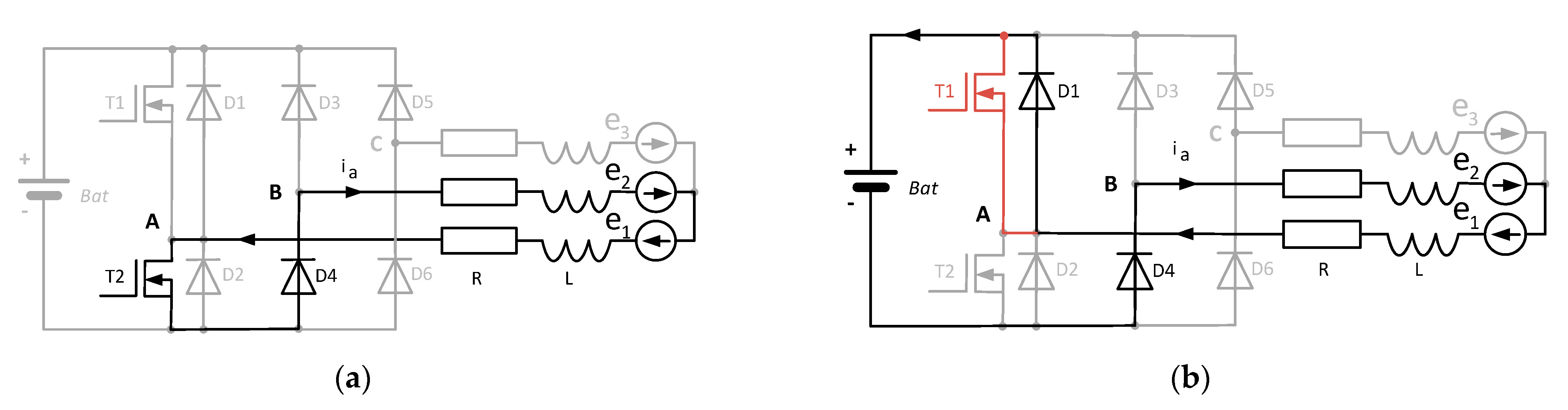
Both operating stages in the first sector of 0–π/2 are shown in
Figure 3a,b, respectively.
The two-switch converter also has a great advantage for synchronous conduction in a branch with power MOSFET transistors. For instance, when the T2 transistor turns off, the T1 transistor conducts (if it has a turn-on signal) a backwards load current instead of diode D1 (highlighted in pale pink in
Figure 3b). This is particularly noticeable for a duty cycle coefficient close to 50%. By employing synchronous conduction, a large reduction of power losses can be achieved, especially in low voltage operating systems.
In the steady state, the voltage across the generator phase inductance
L is expressed as follows:
The generator average interphase voltage can be expressed as follows:
where
e1(
t) and
e2(
t) are the instantaneous values of the phase voltage,
a is the voltage coefficient,
Urms is the rms phase voltage, and
k is the back EMF constant.
The average inductor voltages are given as follows:
where
D is the PWM duty cycle,
T is the period time,
Ia is the average generator current,
RBat is the battery internal resistance,
R is the generator phase resistance,
RDSON is the static drain-to-source on-resistance of the transistor,
UBat is the battery voltage, and
UF is the forward voltage drop of the diode.
The output power of generator
Pout is transferred to the battery at time D-1, therefore the following equation can be written:
Based on (1)–(3), the equation for the current
Ia takes the following form:
The obtained dependencies allow for plotting the
Pout versus current
Ia used in the experimental study for the Parvalux PBL-60-78 motor shown in
Figure 4.
It can be seen that despite limiting the duty cycle D to 50%, the maximum output power Pout is achieved for a wide range of rotational speeds. Overall, the output power is less than in the tree-phase full bridge rectifier with the boost converter due to the lower value of the generator’s average rectified voltage. Comparing the average values of the rectified voltages for the two-switch converter (calculated from Equation (2)) and the three-phase bridge rectifier, we obtain 2.13 Urms/234 Urms = 0.91. Thus, the average value of the input voltage of the discussed converter is 9% smaller. However, considering its advantages, this type of converter is suitable for use with small wind turbines.
In the following part of the paper, simulation and experimental results for the three-phase full bridge rectifier with the boost converter and bridge converters using three- and two-switch transistors employing sensor-less control methods are presented.
4. Simulation Results
Simulations were conducted by means of TCAD software dedicated to power electronics and electric machine drive systems. The Parvalux PBL-60-78 PM motor used in the research station was modelled as the serially connected AC voltage source, phase resistance Rf, and inductance Lf. The power switches, including diodes (HFA15TB60) and transistors (IRFP90N20D), were represented by serially connected constant voltage source and dynamic resistance. Based on the technical datasheet and measurements, the following values were assumed: U = 0.004 V/rpm, Rf = 0.45 Ω, Lf = 1.1 mH, ΔU
AK = 1.15 V,
RDON = 0.05 Ω, Δ
USD = 0 V,
RDSON = 0.023 Ω, L = 200 uH, and Rp = 0.25 Ω. The switching frequency of the transistors is fs = 20 kHz and the battery voltage is 25 V.
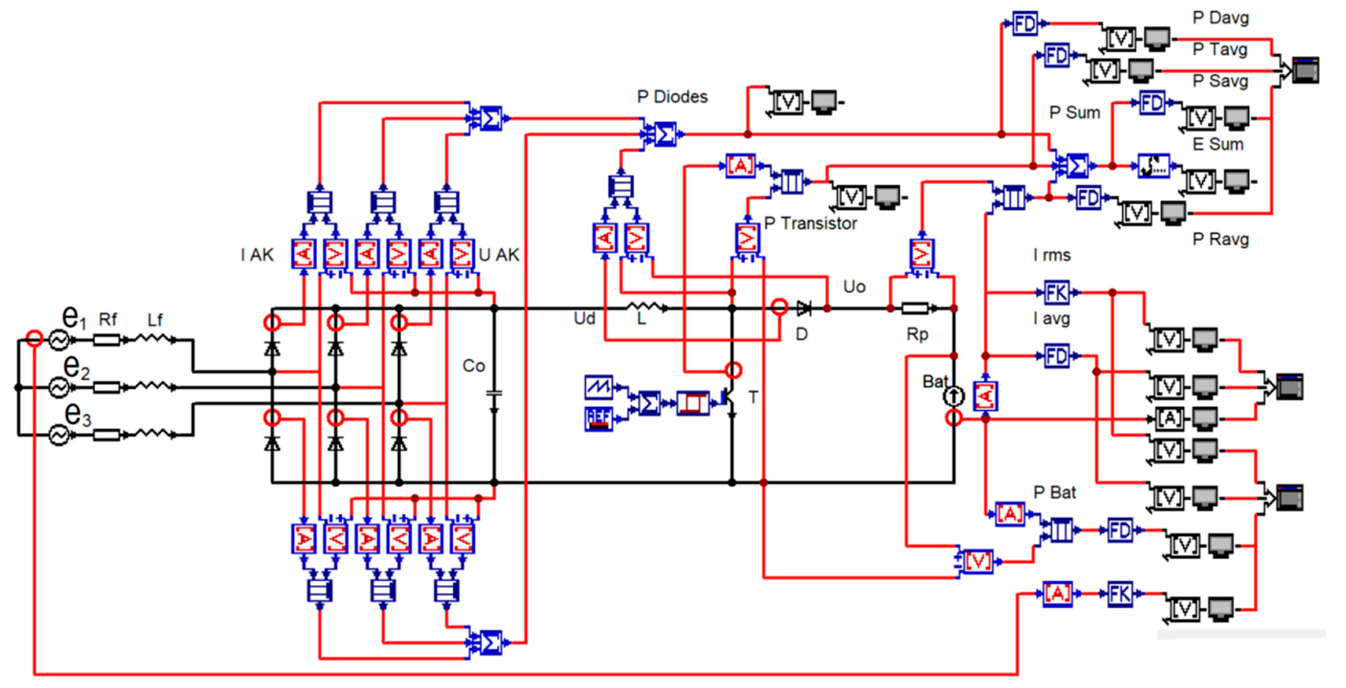
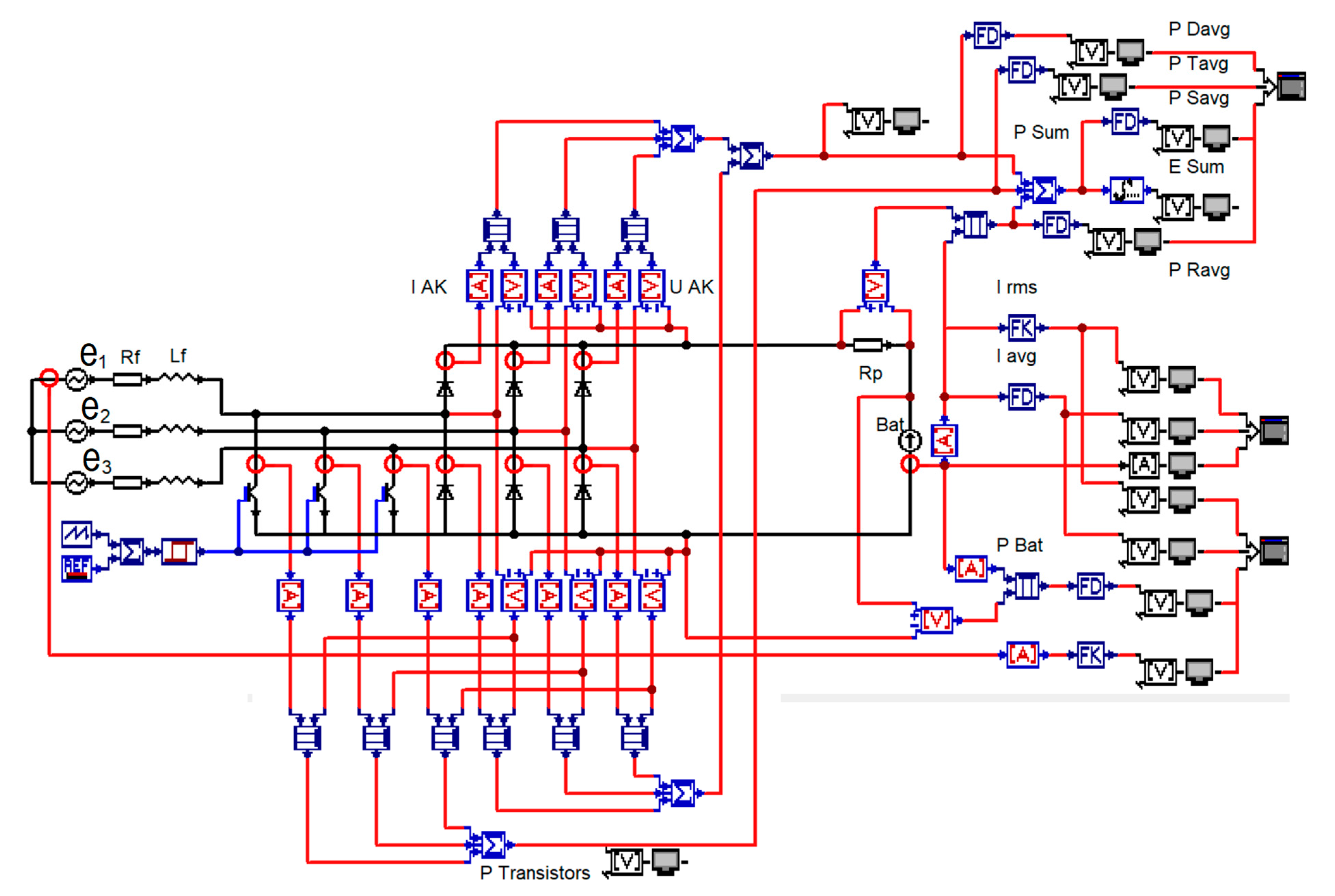
Figure 5 shows the simulation circuit of the tree-phase full bridge rectifier with the boost converter.
To obtain the total power losses of the converter, the power loss of each diode was calculated, and the results were summed up and then the transistor power loss was added. The generator output power
Pout was calculated as the sum of the battery power and the total power loss of the converter. The efficiency of the converter was calculated as the quotient of the battery power and the converter output power.
Figure 6 and
Figure 7 show simulation circuits of the three- and two-switch converter obtained by using the method applied to three-phase bridge rectifier with the boost converter, respectively.
Simulation tests were carried out by varying the PWM duty cycle coefficient from 10% to 90% for the two converters, and from 10 to 49% for the two-switch converter. Two rotational speeds of the PM generator (3000 and 4000 rpm) were applied in the simulation tests.
The results of the simulation studies in the form of the characteristics of the converter output power as a function of the generator rms phase current value are shown in
Figure 8.
Figure 9 presents the efficiency of the converter as a function of the rms generator phase current.
The obtained characteristics show that the three-phase full bridge rectifier with the boost converter is characterized by the lowest efficiency in the whole range of rms generator phase current variation. It is caused by the fact that the converter of this type has three diodes conducting at the same time during the energy recovery stage. The voltage drop across the diodes is the major source of power loss for a converter fed from a low voltage source. For this reason, this type of converter was not considered in further experimental studies. The two other converters are distinguished by their much higher efficiency. The output power of the two-switch converter is limited by the sensor-less control algorithm, in which the PWM duty cycle must be less than 50%.
6. Conclusions
Currently, there is a high demand for inexpensive systems that utilize wind energy for power various types of electrical equipment. A significant reduction of the cost is possible by using a sensor-less PM generator control system. The construction costs of the analyzed converters are shown in
Table 2 and can be divided into the following main components: power switches, control unit, LC passive components, and remaining (e.g., housing, PCB board, and assembly).
To estimate the value of the converter, the cost per one power diode was used as a reference. For instance, three transistors with a cost of components 4 gives a value of 12. Even though these are approximate values based on the current wholesale prices of the electronic components, they reflect the price level of a particular converter. The analysis of a sensor-less power converters shows that the widely used full bridge rectifier with the boost converter had the lowest efficiency. This is the effect of three diodes conducting simultaneously in the energy recovery stage. Therefore, this type of converter should not be used with low output voltage PM generators (less than about 100 V). In addition, its construction costs may not be the lowest due to the inductance L.
In the experimental research, the three-switch converter obtained a higher output power and efficiency than the two-switch one. This is a result of the wider range of the PWM duty cycle control. However, the cost of the three-switch converter is higher.
The difference between the manufacturing cost of a given converter seems to be small (varies within 12–15% between particular solutions). However, when hundreds or thousands of items are produced, the total effect of the financial profit is large. Whether this profit is significant with respect to the entire wind turbine depends mainly on its nominal output power. As the output power of the wind turbine increases, the cost-effectiveness of the proposed solution will decrease because the share of construction and mechanical costs is dominant. Comparing the prices of the popular solutions on the market (
https://news.energysage.com/small-wind-turbines-overview/ (accessed on 15 August 2021)), it can be concluded that the proposed solution is attractive for small off-grid small wind turbines with a nominal output power up to about 2 kW. Then, the cost of the converter varies from
$30 (e.g., Pikasola Wind Turbine Charge Controller 400–600 W) up to
$200 (e.g., Pikasola 1400 W).
To fully utilize the advantages of synchronous conduction in the two-switch converter, pulse density modulation PDM can be used instead of PWM modulation. If the main criterion for the application of a power converter is the relation of its cost to capabilities, the two-switch converter is a good choice. It has high efficiency due to the synchronous conduction of the power MOSFET transistor, a good reliability, and also a simple structure and control.


