Article

Maximum Power Extraction from Wind Turbines Using a Fault-Tolerant Fractional-Order Nonsingular Terminal Sliding Mode Controller

by
Yashar Mousavi
1,*,
Geraint Bevan
1,
Ibrahim Beklan Küçükdemiral
1 and
Afef Fekih
2,*
1
Department of Applied Science, School of Computing, Engineering and Built Environment, Glasgow Caledonian University, Glasgow G4 0BA, UK
2
Electrical and Computer Engineering Department, University of Louisiana at Lafayette, P.O. Box 43890, Lafayette, LA 70504, USA
*
Authors to whom correspondence should be addressed.
Energies 2021, 14(18), 5887; https://doi.org/10.3390/en14185887
Submission received: 5 July 2021 / Revised: 9 September 2021 / Accepted: 13 September 2021 / Published: 17 September 2021

Abstract

:
This work presents a nonlinear control approach to maximise the power extraction of wind energy conversion systems (WECSs) operating below their rated wind speeds. Due to nonlinearities associated with the dynamics of WECSs, the stochastic nature of wind, and the inevitable presence of faults in practice, developing reliable fault-tolerant control strategies to guarantee maximum power production of WECSs has always been considered important. A fault-tolerant fractional-order nonsingular terminal sliding mode control (FNTSMC) strategy to maximize the captured power of wind turbines (WT) subjected to actuator faults is developed. A nonsingular terminal sliding surface is proposed to ensure fast finite-time convergence, whereas the incorporation of fractional calculus in the controller enhances the convergence speed of system states and simultaneously suppresses chattering, resulting in extracted power maximisation by precisely tracking the optimum rotor speed. Closed-loop stability is analysed and validated through the Lyapunov stability criterion. Comparative numerical simulation analysis is carried out on a two-mass WT, and superior power production performance of the proposed method over other methods is demonstrated, both in fault-free and faulty situations.

1. Introduction

With the current fast-growing developments in industrialization and the usage of electrical devices, and due to the increasing global concerns on climate change, developing environmentally friendly power production resources has become a popular topic of many studies in industry and academia. As an emerging renewable energy technology, wind energy conversion systems (WECSs) have established themselves as efficient and reliable emission-free alternative power production technologies. However, as these complex systems continue to grow in size and power, more reliable and effective control strategies are expected to guarantee cost-efficiency and higher-quality power production capabilities of WECSs [1,2,3].
To extract maximum power while maintaining safe operation, wind turbine (WT) operating conditions are categorized into four regions based on wind speed [4] as illustrated in Figure 1. In regions I and IV, the wind speed is below the cut-in speed Vcut-in and above the cut-out speed Vcut-out, respectively. Accordingly, the WT is either unable to provide the expected power (region I) or would suffer from high mechanical loads leading to damage (region IV); hence, the WT is shut down in both regions. When the wind speed is between the cut-in and the rated speed V r a t e d (region II or partial-load region), where the rated speed is the speed at which the WT is able to provide the power with its maximum capacity, torque control approaches are used to control the generator torque and maximize the power capture. When the wind speed exceeds the rated value and is below the cut-out speed, the WT enters its third operating region (region III or full-load region), where pitch control and power regulation approaches keep the captured power at the rated value ( P g , r a t e d ) and prevent the turbine from damage. In order to maximize the wind energy extraction in a variable speed WT operating in region II, the rotor speed is regulated to track its continuously fluctuating optimum value, and hence maintain the optimum tip-speed ratio [5].
Various linear and nonlinear control strategies have tackled this tracking problem to achieve the maximum power extraction objective such as adaptive neural network (NN) -based control [6], backstepping-based cascade control [7], optimal control [8], optimal nonlinear model predictive control (MPC) [9], and neuro-adaptive sliding mode control [10]. Recently, the authors in [11] developed two fractional-order fast terminal sliding mode controllers to reduce the mechanical stress on the drivetrain and maximise the captured power of variable-speed WTs. A fractional-calculus-based model of the WT was presented, where the proposed controllers have successfully performed the maximum power extraction task. However, although the aforementioned studies have successfully dealt with the power maximization problem of WT systems despite the wind speed variations, a critical issue in WT control systems remains neglected: the existence of actuator faults that degrade the overall system’s stability and power production performance. Hence, developing a fault-tolerant robust control scheme capable of accommodating the faults’ effects can be favourable to ensure the desired power production performance. In this regard, an active fault-tolerant control (FTC) for a doubly-fed induction generator (DFIG) -based WT with actuator fault and disturbance was developed in [12]. The control structure comprised a Takagi–Sugeno fuzzy observer to estimate the faults and disturbances and an FTC scheme to reduce their effects. As reported, the developed active FTC scheme has successfully reduced the peak current in the transient process. In another study [13], an adaptive modified PID controller was proposed to maximize the captured power of WT systems. According to the authors, the developed approach demonstrated more acceptable performance compared to other classical methods in dealing with unexpected actuator faults and wind speed fluctuations. However, the controller requires further improvements in order to mitigate the fault effects. The authors in [14] proposed an actuator fault diagnosis and FTC approach by incorporating a Takagi–Sugeno fuzzy system and a sliding mode observer for WTs with a hydrostatic transmission. The simulation results were reported to demonstrate a similar performance of the fault-free and faulty cases, revealing the desirable performance of the FTC approach. In another study [15], an active FTC scheme was developed for rotor speed regulation and maximum power extraction of a WT in the presence of actuator faults and uncertainties. In this regard, the authors designed a full-order compensator for fault and disturbance attenuation and an adaptive output feedback sliding mode controller (SMC) with an integral surface to perform the FTC. The proposed strategy was reported to demonstrate better fault-tolerant capability and more robust behaviour with fewer fluctuations and less fatigue on the rotor speed and output power than conventional PID and disturbance accommodation controllers.
Stemming from the desirable merits of SMC approaches, such as fast dynamic response, good transient performance, stability, and robustness to matched parameter uncertainties, it has established itself as one of the most effective strategies to deal with different linear and nonlinear control problems [16,17,18,19]. In this regard, due to the highly nonlinear behavior of WECSs, power control and performance enhancement of these systems have been the topic of many SMC-based control strategies during the past decade [20,21,22]. The authors in [20] developed an improved SMC controller with reduced chattering for power maximization of a grid-connected DFIG-based WECS under bounded uncertainties and disturbances. In another study [21], an exponential reaching law was proposed to reduce the chattering phenomenon and enhance the WT active and reactive power control performance in an SMC controller. In a similar study [22], an improved SMC was developed to deal with the active and reactive power control problems of a DFIG-based WT subjected to various uncertainties. As reported, comparative investigations of the developed SMC approach and the H robust control method demonstrated superior performance in terms of tracking error, overshoot, and settling time. The conventional SMC is relatively straightforward to design and implement. However, despite its satisfactory performance in practical applications, it has some defects, such as the chattering problem, failing to establish a finite-time convergence of the systems states to the equilibrium point, and producing unnecessarily large control signals [23]. Accordingly, to overcome these shortcomings and enhance their performance, various modifications have been developed in the literature, such as adaptive SMC [24], higher-order SMC [25,26,27], soft computing-based SMC [28,29], and fractional calculus-based SMC [30,31]. Higher-order SMCs, such as terminal SMC (TSMC) approaches, have successfully dealt with the finite-time convergence and large control signal problems associated with conventional SMCs [32]. However, regardless of their provided improvements, they still need further chattering mitigation and convergence speed improvements. On the other hand, due to the distinctive memory features of fractional-order derivatives [33], the augmentation of fractional-order calculus with linear and nonlinear controllers has led to enhanced performance in many control applications [34,35]. In this context, the synthesis of fractional calculus with SMC controllers has shown to be an effective amendment to the controllers’ performance by mitigating the chattering phenomenon and delivering faster convergence speed [30,36,37].
In accordance with the above-discussed literature and considering the desirable performance of SMC approaches in WT control problems, this work proposes a fractional-order nonsingular terminal sliding mode controller to maximize the power extraction of WECSs operating in the partial-load region. Its main contributions are as follows:
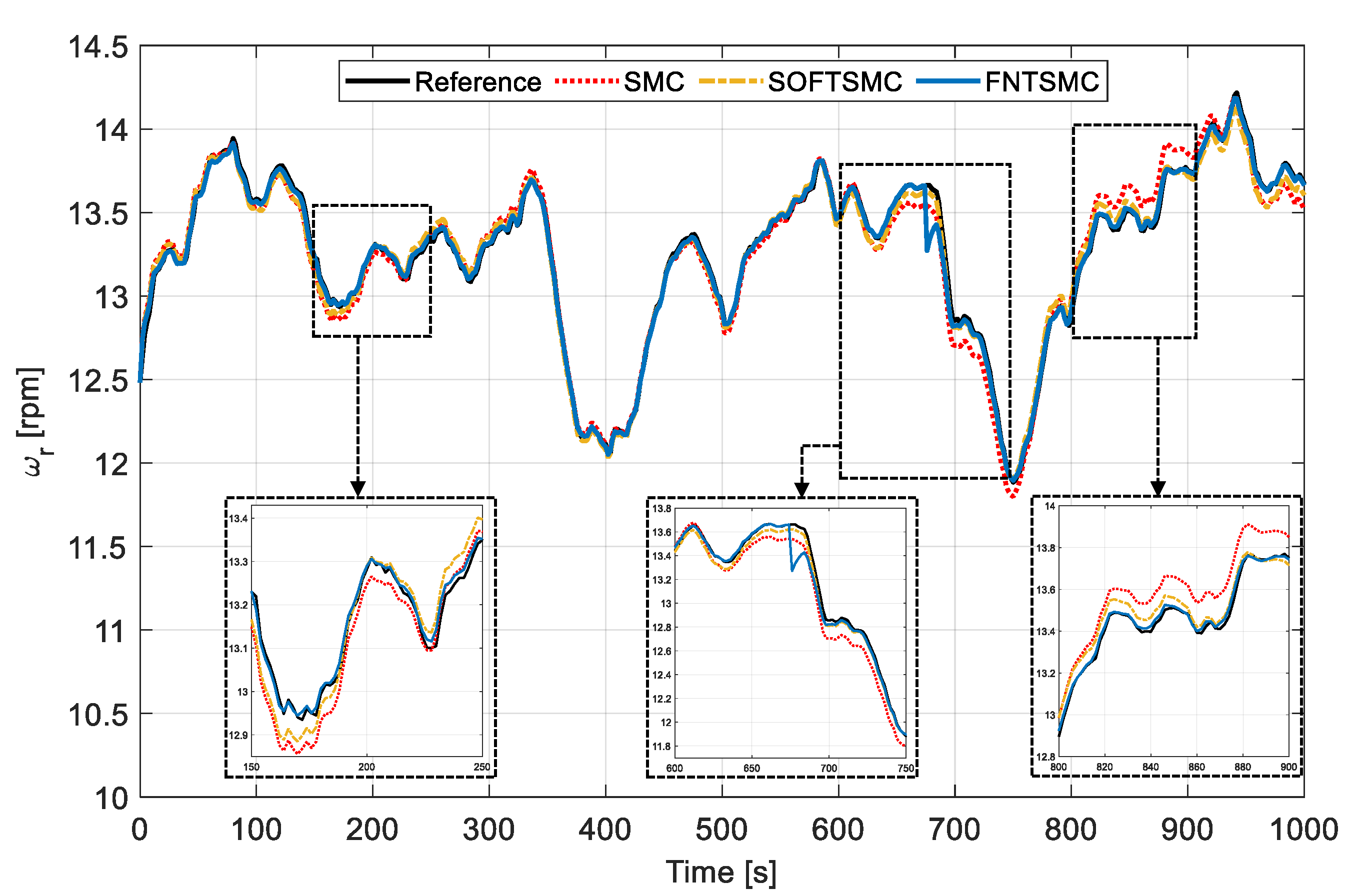
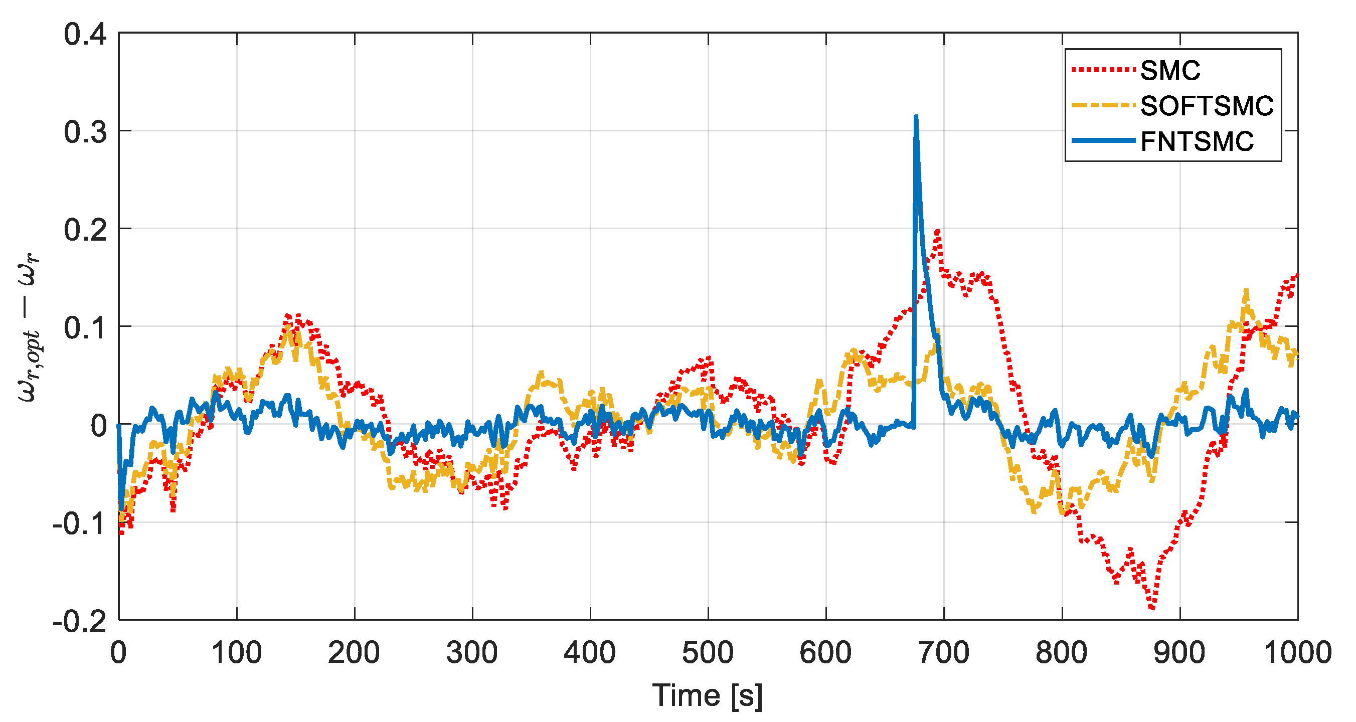
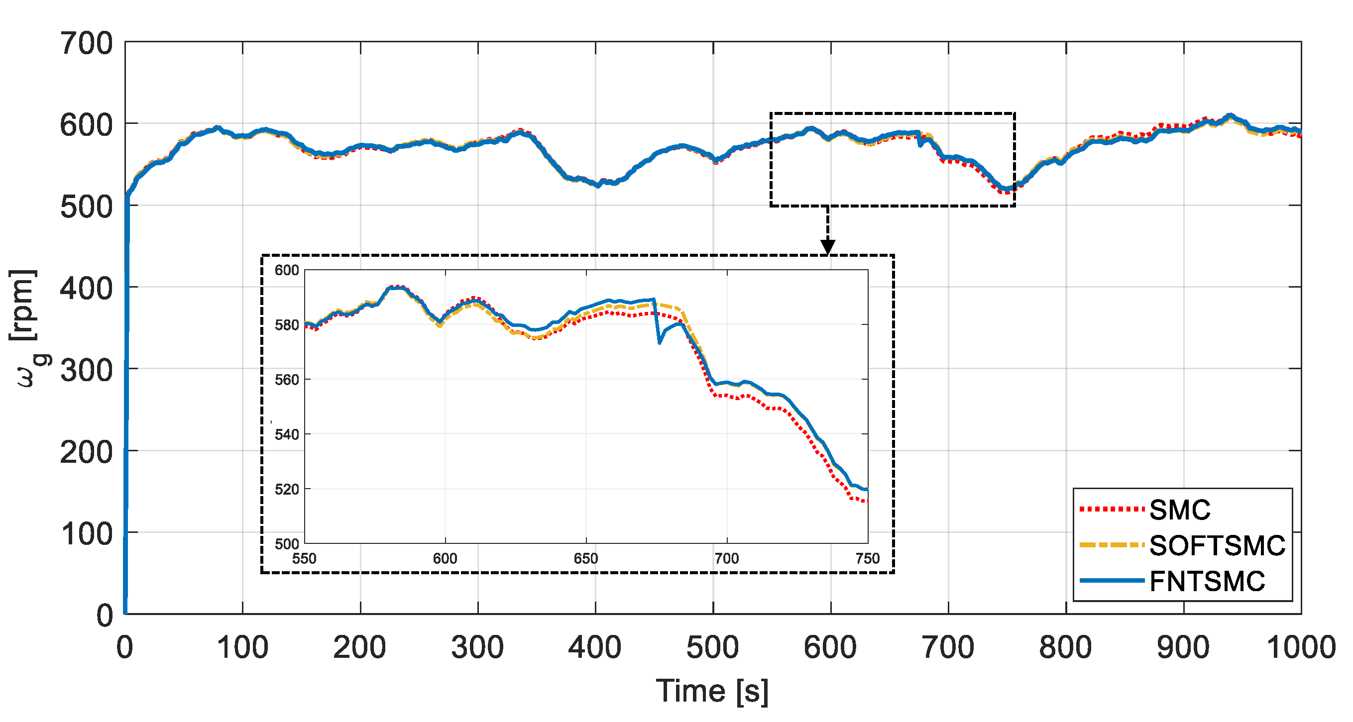
  • A design that integrates the fractional calculus into NTSMC to effectively enhance the finite-time convergence speed and simultaneously alleviate the chattering phenomenon. Therefore, the optimum rotor speed tracking is achieved with little error, resulting in more power extracted from the wind;
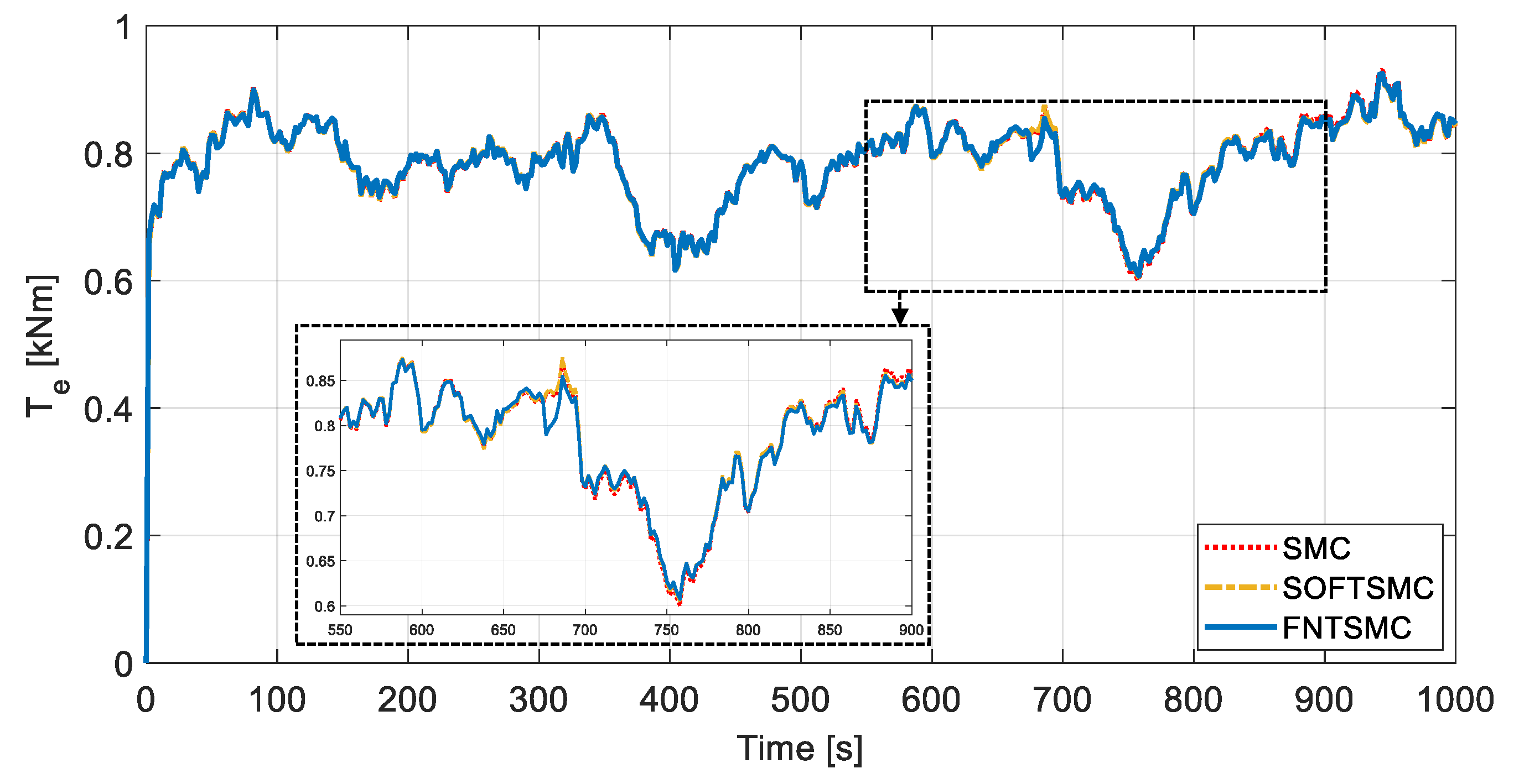
  • Validation and performance assessment of the fault-tolerant capability of proposed design using partial loss on the generator torque;
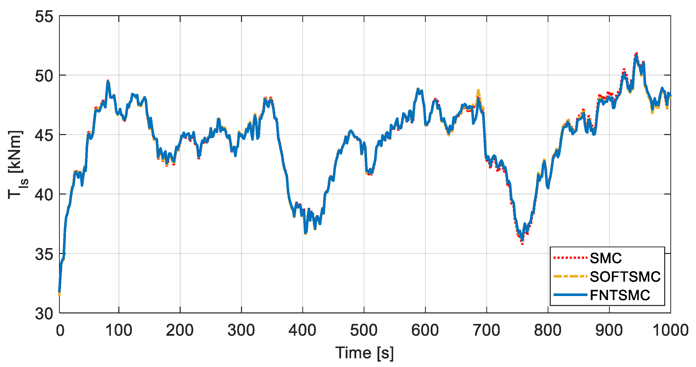
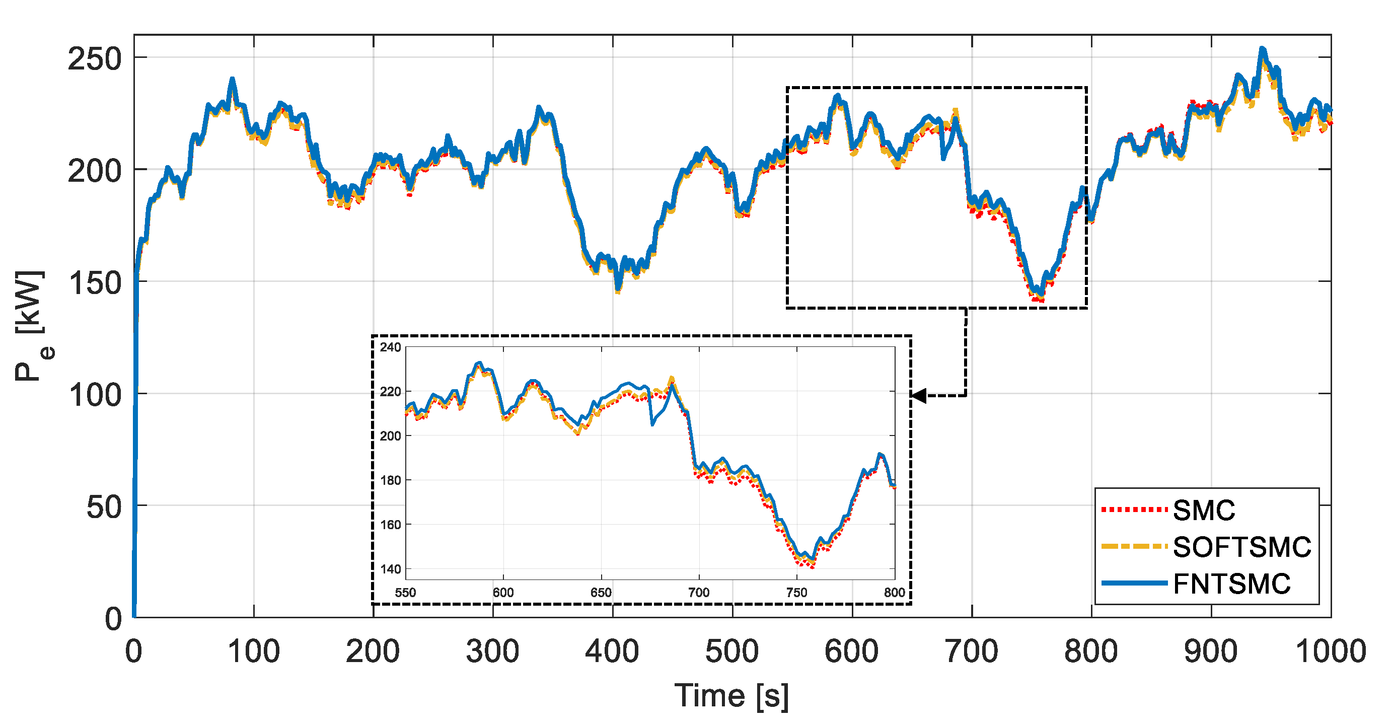
  • Comparative performance analysis of the developed control strategy with conventional SMC [38] and second-order fast terminal SMC [39]. Accordingly, taking advantage of the proposed control law, a desirable optimum rotor speed tracking performance with fewer fluctuations and faster transient response is achieved.
The remainder of the paper is organised as follows. Section 2 presents the modelling of the two-mass WT along with the problem statement and fault description. Section 3 is dedicated to the proposed controller’s design process and presents the stability analysis based on the Lyapunov stability theorem. Section 4 presents the comparative simulation results, and finally, some conclusions are given in Section 5.

2. Problem Formulation

In this section, the two-mass WT model under study is first presented. The power capture maximization problem in the partial-load region alongside the considered actuator fault are then introduced.

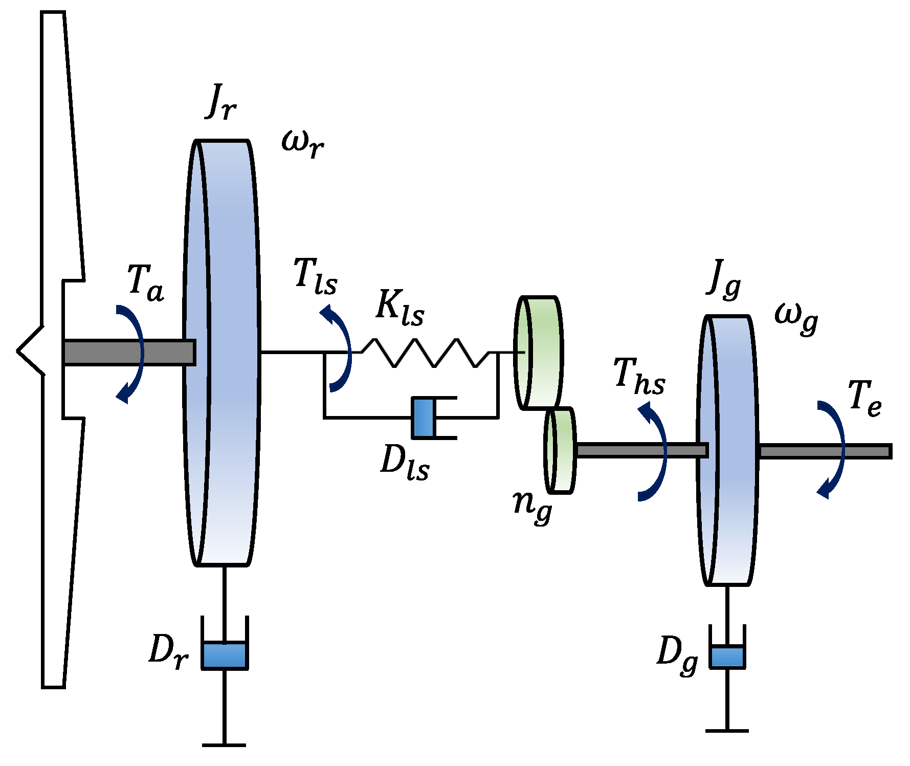
2.1. Wind Turbine Model

The wind energy conversion system comprises four main subsystems, including aerodynamics, turbine mechanics, actuator dynamics, and generator dynamics. The aerodynamic subsystem represents the conversion of wind power to rotational energy, where its characteristics are affected by the wind speed, pitch angles of the blades, and rotor speed. The aerodynamic power extracted by the WT can be expressed as follows [40]:
P a t = 1 2 ρ π R 2 υ w 3 t C P λ t , β t ,
where ρ represents the air density in [ kg / m 3 ], R is the rotor radius in [ m ], υ w t is the wind speed at the rotor plane, and t represents time in [ s ]. The dimensionless power coefficient C P depends on both the tip-speed ratio λ = R ω r / υ w and pitch angle β in degrees. The rotational speed of the rotor is calculated as ω r = η g ω g in [ rad / s ], where η g and ω g are the generator’s efficiency and rotational speed, respectively.
Remark 1.
Using some nonlinear curve-fitting techniques, the power coefficient can be approximated by a mathematical function, expressed as follows [41]:
C P λ , β = C 1 C 2 Λ C 3 β C 4 e C 5 / Λ + C 6 λ ,
where C 1 = 0.5176 , C 2 = 116 , C 3 = 0.4 , C 4 = 5 , C 5 = 21 , C 6 = 0.0068 , and
Λ = 1 λ + 0.08 β 0.035 β 3 + 1 1 .
The drivetrain provides the generator’s required rotational speed by converting high torque on the low-speed shaft to the low torque on the high-speed shaft to be transferred to the generator unit. The mechanical model of the two-mass WT represented by Figure 2 can be described as follows [15],
J r ω ˙ r = T a T l s D r ω r ,
J g ω ˙ g = T h s T e D g ω g ,
θ ˙ Δ = ω r ω g n g ,
where T l s = k l s θ r θ l s + D l s ω r ω l s and T h s = T l s / n g represent the low and high speed shaft torque, respectively. θ Δ = θ r θ l s denotes the torsion angle of drivetrain, J r represents the rotor inertia, J g is the generator inertia, T a = P a / ω r is the aerodynamic torque, and T e is the generator torque. k l s is the low shaft speed stiffness, ω l s is the low shaft speed, and θ r and θ l s represent the rotation angle of the rotor and generator shafts, respectively. D r , D g , and D l s are the rotor external damping, the generator external damping, and low-speed shaft damping, respectively. The gearbox ratio is expressed as:
n g = ω g ω l s = T l s T h s = θ g θ l s .
Using (4) and (5), one can obtain
J t ω ˙ r = T a D t ω r T g ,
where J t = J r + n g 2 J g , T g = n g T e , and D t = D r + n g 2 D g denote the induced total inertia, generator torque on the rotor side, and the induced total external damping on the rotor side, respectively.
The dynamics of the generator are modelled as a first-order system to track the requested generator torque T e , r e f as T e ˙ = T e / τ T + T e , r e f / τ T [40], where τ T denotes the time constant. Accordingly, the electrical power produced in the generator can be expressed as P e = η g ω g T e , where η g represents the generator efficiency.

2.2. Problem Statement

The control objective is to extract the maximum power from the wind energy in the partial-load region. To this end, the power coefficient C P needs to be obtained based on the optimum pitch angle β o p t t and the optimum tip speed ratio λ o p t t , i.e., C P , max C P λ o p t t , β o p t t , where C P , max denotes the maximum power coefficient. As a common procedure, when the wind speed υ w t exceeds the rated wind speed, υ w , r a t e d t , some pitch angle control strategies such as adaptive PI controller [42], fuzzy-PI controller [43], and gain-scheduling fractionalo-order PID [44] are implemented to adjust β t and ensure ω r t tracks the rated rotor speed ω r , r a t e d t .
In this work, the focus is on the case that υ w t is lower than υ w , r a t e d t (i.e., region II) and β t is fixed at β = 0 . Accordingly, the aerodynamic power can be represented as follows:
P a * t = 1 2 ρ π R 2 υ w 3 t C P , o p t λ o p t t , β t ,
where C P , max C P λ o p t t , 0 .
Hence, the control objective is to define a control law that maximizes the power extraction by maintaining the maximum rotor efficiency during operation, by adjusting the rotor speed ω r t to follow the optimum rotor speed ω r , o p t t and as a result, ensure λ t = λ o p t t for t 0 . Accordingly, the reference rotor speed can be derived as follows,
ω r , o p t t = λ o p t t υ w t / R .
Therefore, the maximum power extraction is achieved when e t = ω r , o p t t ω r t converges to zero as t goes to infinity.

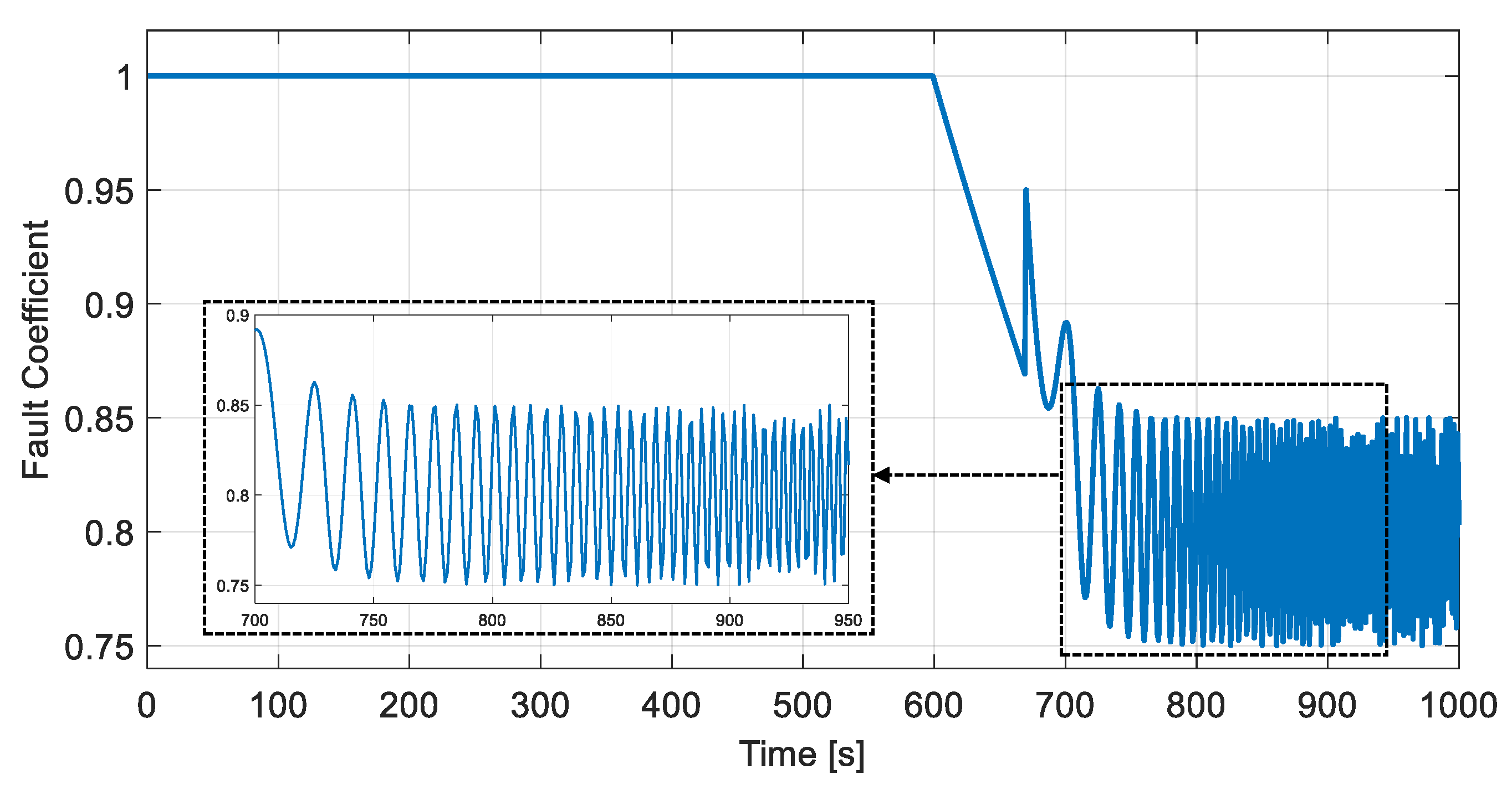
2.3. Actuator Faults

Faults in a WT system can be classified into two main categories in terms of severity. The first category consists of highly extreme faults such as actuator/pitch breakdown, which requires immediate shutdown or grid disconnections to ensure the system’s safety. In contrast, the second category comprises the non-extreme faults such as sensor or actuator degradation, where fault-tolerant strategies are usually adopted to preserve the system’s operation with minimum performance degradation. Since this study focuses on the power maximization and tracking control at below-rated wind speeds (i.e., υ w t < υ w , r a t e d t ), the non-extreme actuator fault scenario will be considered. To this end, the actual control input u f t and the designed control input u t are expressed as follows [45]:
u f t = ζ t u t ,
where the actuator efficiency factor (or the health indicator [45]) ζ t is a time-varying scalar function within interval ζ ( 0 , 1 ] , where 0 and 1 correspond to total power loss and healthy actuation, respectively.
The actuator fault considered in this study is a partial loss of the generator output torque. The WT encounters an actuator failure and loses partial actuation power after t = 600 s. The actuator efficiency coefficient is chosen as follows and depicted in Figure 3.
ζ t = 1 , if t < 600 ζ t 1 0.995 , if 600 t < 670 4 5 + 1 5 exp t 670 20 1 20 chirp π t 670 1000 , if t 670
The actuator failure’s complex fluctuation characteristics that are found in practice are simulated using the “ chirp ” function. The “ chirp ” sweep signal is used to verify the controller’s performance in the case of faults with varying frequencies as occurs in real engineering applications.

3. Controller Design

In this section, some brief preliminary concepts of fractional calculus will be presented, and then the proposed FNTSM controller aiming at power maximization of WT will be investigated.

3.1. Preliminaries on Fractional Calculus

As a generalization of integer-order calculus, the general representation of the fractional-order integrator and differentiator can be expressed as t 0 D t γ , with t 0 as the initial time, and γ as the fractional order, where positive and negative values of γ represents the integration and differentiation characteristics, respectively. In the literature, fractional differential operators have been investigated with various definitions [46]. In this study, the Riemann–Liouville (RL) definition is used in the following form
t 0 D t γ f t = d γ f t d t γ = 1 Γ n γ d n d t n t 0 t f τ t τ γ n + 1 d τ , t > t 0 ,
where n 1 γ < n and n N represents the first integer. Γ t = 0 e u u t 1 d u denotes the Gamma function [46]. It is worth mentioning that the RL derivative (11) executes the derivation operation after integration; hence, the fractional-order derivation of a constant number is not zero.
The Laplace transformation of the fractional-order derivation can be expressed as:
0 0 D t γ f t e s t d t = S γ L f t σ = 0 n 1 S σ 0 D t γ σ 1 f f | t = 0
In this work, the filter constructed by the Oustaloup algorithm [46] is used to approximate the fractional operators and synthesize them in the frequency domain by a recursive distribution of zeros and poles expressed in the following form.
S γ K n = N N 1 + S / ω z , n 1 + S / ω p , n , γ > 0
ω z , n = ω b ω h ω b n + N + 1 γ 2 / 2 N + 1
ω p , n = ω b ω h ω b n + N + 1 + γ 2 / 2 N + 1
where K = ω h γ represents the adaptive gain, the number of poles and zeros is 2 N + 1 , and the upper and lower constraints of the approximation frequency are ω h and ω b , respectively. More detailed information regarding stability analysis and convergence speed of fractional-order systems can be found in [30].

3.2. Proposed FNTSMC Controller

In this section, the maximum power extraction of WT is accomplished by rotor speed regulation so that the rotor speed tracking error e = ω r , o p t ω r is minimized. For simplification of writing, the t index is neglected in the equations. A fractional-order nonsingular terminal sliding (FNTS) surface is proposed as follows,
s = ϕ e + D γ 1 e + 1 α 1 e l h + 1 α 2 e ˙ p q ,
where ϕ > 0 , α 1 > 0 , α 2 > 0 , l > 0 , h > 0 , p > 0 , p > 0 , are odd positive integers satisfying 1 < p q < 2 , 1 < l h < 2 , and p q < l h . D γ · represents the RL fractional derivative of order 1 < γ < 2 .
Remark 2.
When the system state is far from the equilibrium point, the term D γ 1 e in (14) plays the main role by dominating the term 1 α 1 e l / h + 1 α 2 e ˙ p / q , and guarantees a high convergence rate. Subsequently, as the system state approaches the equilibrium point, the term 1 α 1 e l / h + 1 α 2 e ˙ p / q plays the main role and ensures a finite-time convergence.
Differentiating (14) with respect to time yields
s ˙ = ϕ e ˙ + D γ e + l α 1 h e l h 1 e ˙ + p α 2 q e ˙ p q 1 e ¨ .
Moreover, since 1 < p q < 2 , 1 < l h < 2 , and p q < l h , the singularity problem during the convergence of the terminal SMC is avoided. Considering (6), (15) can be rewritten as
s ˙ = D γ e + p α 2 q e ˙ p q 2 B e ˙ 3 p q + e ˙ ω ¨ r , o p t T ˙ a D t ω ˙ r J t + n g J t T ˙ e ,
where B = α 1 p h 1 α 1 α 2 ϕ q h + α 2 q l e l h 1 .
Setting s ˙ = 0 , the following control law can be derived,
T ˙ e = n g J t 1 α 2 q p e ˙ 1 p q D γ e B e ˙ 2 p q ω ¨ r , o p t + T ˙ a D t ω ˙ r J t .
Remark 3.
It is worth mentioning that taking advantage of the developed control law (17), the system state remains on the sliding surface (14) and satisfies the condition s ˙ = 0 . Hence, the finite-time convergence of the tracking error to zero is guaranteed. However, in order to force the state toward the sliding surface in finite time and satisfy the sliding condition, a fractional-order switching law is suggested as follows:
T ˙ e , s w = n g J t 1 α 2 q p e ˙ 2 p q D γ 1 F s sgn s + ψ s ,
where ψ > 0 , D γ F s = κ s , κ > 0 , and F s is an arbitrary positive auxiliary function.
Accordingly, combining (17) and (18), the equivalent control law can be expressed as:
T ˙ e , e q = T ˙ e + T ˙ e , s w = n g J t 1 ( α 2 q p e ˙ 1 p q D γ e B e ˙ 2 p q ω ¨ r , o p t + T ˙ a D t ω ˙ r J t + α 2 q p e ˙ 2 p q D γ 1 F s sgn s + ψ s ) .
The block diagram of the proposed control scheme is illustrated in Figure 4.
Theorem 1.
By employing the FNTS surface (14) and the switching control law (18), the tracking error dynamics reach the sliding surface in finite time and then converge to zero asymptotically.
Proof of Theorem 1. 
Consider the following Lyapunov function candidate:
V = 1 2 s 2 + 1 2 κ D γ 1 F s 2 .
Derivation of V with respect to time yields
V ˙ = s s ˙ + 1 κ D γ 1 F s D γ F s = s s ˙ + D γ 1 F s s .
Taking the equivalent control law in the form of (19) and substituting (16) into (21), we obtain
V ˙ = s D γ e + p α 2 q e ˙ p q 2 B e ˙ 3 p q + e ˙ ω ¨ r , o p t T ˙ a D t ω ˙ r J t + n g J t T ˙ e , e q + D γ 1 F s s 0 .
Considering (22), it can be verified that
V ˙ = s D γ 1 F s sgn s ψ s + D γ 1 F s s D γ 1 F s s ψ s 2 + D γ 1 F s s ψ s 2 < 0 .
Thus, asymptotical convergence of the system states to the FNTS surface s t = 0 is achieved according to the Lyapunov stability criterion. From the Lyapunov function (20) we have
s 2 = 2 V + 1 κ D γ 1 F s 2 .
Hence, the finite-time convergence can be investigated by rewriting (23) as follows,
V ˙ = d V d t ψ s 2 = 2 ψ V ψ κ D γ 1 F s 2 .
From (25) the following inequality can be obtained,
d t d V 2 ψ V ψ κ D γ 1 F s 2 .
Let t e , r represent the reaching time at which the regulation error reaches the sliding surface ( e 0 0 e = 0 , i.e., V ( t e , r ) = 0 ). Then, integrating both sides of (26) yields
0 t e , r d t V 0 V t e , r d V 2 ψ V ψ κ D γ 1 F s 2 = 1 2 ψ ln 2 ψ V ψ κ D γ 1 F s 2 V 0 V t e , r ,
which further yields
t e , r 1 2 ψ ln ψ κ D γ 1 F s 2 2 ψ V 0 ψ κ D γ 1 F s 2 .
According to the Lyapunov stability criterion and the provided analysis (24)–(28), the finite-time convergence of the NFTS surface (14) to zero is achieved at t e , r . Moreover, s = 0 results in the finite-time convergence of tracking error to zero.
This completes the Proof. □

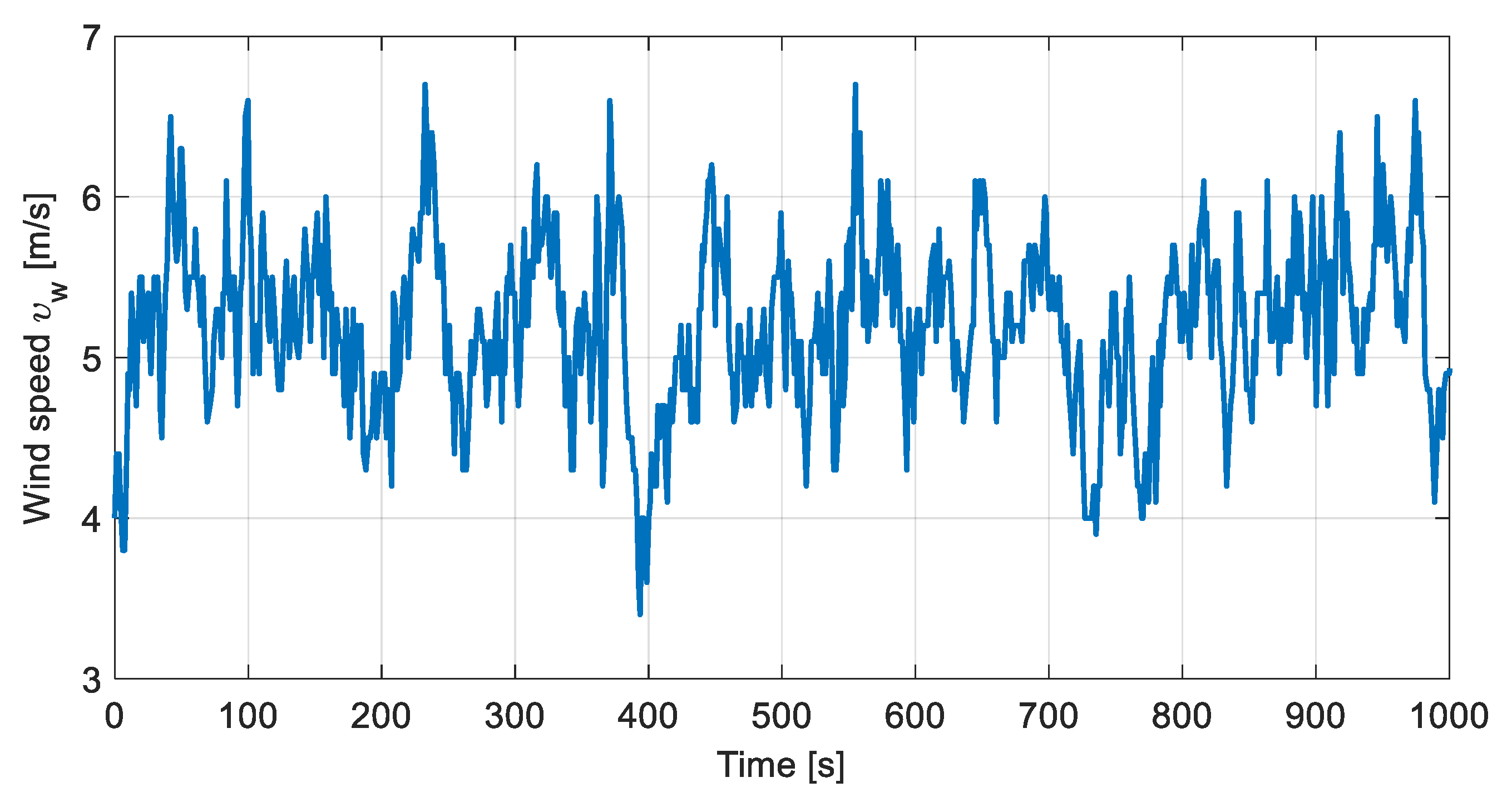
4. Simulation Results

This section studies the power extraction performance of the proposed FNTSMC algorithm. Accordingly, comparative investigations are provided to testify the proposed scheme’s performance in comparison with conventional SMC [38] and second-order fast terminal SMC (SOFTSMC) [39] approaches. The numerical simulations are carried out on a two-mass WT whose characteristics are given in Table 1. The parameters correspond to the two-bladed variable-speed variable pitch controls advanced research turbine (CART) with a hub height of 36 m [47]. The wind profile consists of 1000 s, within the speed range of 3.4–6.7 m / s with an average speed of 5.2 m / s in region II and is shown in Figure 5.
As stated in Section 2.2, the control objective is to capture the maximum power by tracking the rotor speed with and without actuator fault. A partial loss on the generator’s torque is considered as stated in Section 2.3 to demonstrate and verify the fault-tolerant performance of the controllers. Accordingly, during the first 600 s, the wind profile is applied to the system without the existence of any actuator faults. At t = 600 s, the actuator failure starts as a partial linear loss of actuation power and ultimately changes its behavior to nonlinear mode as t = 670 s.
Figure 6 shows the comparative performance illustration of SMC, SOFTSMC, and FNTSMC approaches in tracking the optimum rotor speed. As the zoomed-in insets show, when the fault happens, the SMC controller is unable to supply a convenient control torque for efficient tracking of the optimal rotor speed. In addition, although the SOFTSMC delivers much better performance than that of the conventional SMC, its tracking performance is still inferior to the proposed FNTSMC’s. As one can observe, the proposed FNTSMC controller outperforms other methods and presents a desirable tracking performance with fewer fluctuations and faster transient response. The rotor speed tracking error and generator speed are presented in Figure 7 and Figure 8. From Figure 7, it can be seen that the tracking error associated with the proposed FNTSMC fluctuates in a small region, being six and four times smaller than similar regions for SMC and SOFTSMC, respectively. From Figure 6, Figure 7 and Figure 8 one can observe that, during the initial seconds of fault occurrence (i.e., t = 600–670 s), compared to the SMC and SOFTSMC methods, the FNTSMC demonstrates excellent tracking performance. However, regardless of a bit of fluctuation in the FNTSMC’s performance at t = 670 s, it gets back on track quickly, converges to its previous (no fault) small error region, and successfully tolerates the actuator fault. Furthermore, although SMC and SOFTSMC approaches have delivered acceptable fault-tolerant performances, their performance has been degraded after actuator fault occurrence, showing their weakness in the fault-tolerant task.
Figure 9, Figure 10 and Figure 11, respectively, illustrate the generator torque, low-speed shaft torque, and the electric power comparisons between the control approaches under study. According to Figure 10, it can be seen that, during the fault occurrence, the proposed FNTSMC controller excites the drivetrain less while providing better power capture. Considering Figure 9, Figure 10 and Figure 11, it can be observed that due to embedding the fractional-order component alongside the nonsingular terminal SMC design, the proposed FNTSMC algorithm tracks the rotor speed accurately and provides better power capture in comparison with SMC and SOFTSMC approaches. Accordingly, the weakness of SMC and SOFTSMC approaches in supplying a suitable control torque to efficiently track the rotor speed ω r , o p t is apparent.
To further evaluate the controllers’ performance, a comparative study in terms of the aerodynamic η a e r o and electrical η e l e c efficiencies is carried out, where η a e r o and η e l e c can be calculated as follows:
η a e r o % = t i t f P a t d t t i t f P a * t d t × 100 , η e l e c % = t i t f P e t d t t i t f P a * t d t × 100
where t i and t f denote the initial and final times, respectively. Accordingly, aerodynamic and electrical efficiencies of η a e r o , S M C = 72.72 % , η a e r o , S O F T S M C = 88.18 % , η a e r o , F N T S M C = 91.34 % , η e l e c , S M C = 69.64 % , η e l e c , S O F T S M C = 94.82 % , and η e l e c , F N T S M C = 97.03 % are obtained for the control approaches under study. The achieved foregoing results indicate the superiority of the FNTSMC approach over SMC and SOFTSMC in terms of power capture and aerodynamic and electric efficiency.

5. Conclusions

This paper investigated the maximum power extraction problem of wind energy conversion systems operating below their rated wind speeds in the presence of actuator faults. Accordingly, a fractional-order nonsingular terminal sliding mode controller (FNTSMC) with enhanced finite-time convergence speed of system states and alleviated chattering was proposed to track the optimum rotor speed and maximize the power production. The closed-loop stability of the system and finite-time convergence of tracking error to the equilibrium point were guaranteed using the Lyapunov stability theory. An actuator fault in the form of a partial loss on the generator’s torque was considered to evaluate the fault-tolerant performance and efficaciousness of the proposed method. The performance of the proposed FNTSMC scheme was investigated in comparison with conventional SMC and second-order fast SMC approaches on a two-mass WT system. Simulation results and analysis demonstrated the notable optimal rotor speed tracking performance of the proposed FNTSMC with fewer fluctuations and faster transient response. As a result, its satisfactory power extraction performance with less excitation of the drivetrain was validated compared to conventional SMC and SOFTSMC approaches, both in fault-free and faulty situations. In addition, to further investigate the effectiveness of FNTSMC in terms of speed tracking and power extraction, a comparative study on the aerodynamic and electrical efficiencies of the control approaches was provided. Accordingly, taking advantage of the proposed FNTS surface, a superior power extraction performance was revealed compared to SMC and SOFTSMC.

Author Contributions

Conceptualization, investigation, and writing—original draft preparation, Y.M.; writing—review, editing and supervision, G.B., I.B.K. and A.F. All authors have read and agreed to the published version of the manuscript.

Funding

This research received no external funding.

Institutional Review Board Statement

Not applicable.

Informed Consent Statement

Not applicable.

Data Availability Statement

Not applicable.

Conflicts of Interest

The authors declare no conflict of interest.

Abbreviations

CARTControls Advanced Research Turbine
DFIGDoubly-Fed Induction Generator
FNTSFractional Nonsingular Terminal Sliding
FNTSMCFractional Nonsingular Terminal Sliding Mode Control
FTCFault Tolerant Control
MPCModel Predictive Control
NNNeural Network
NTSMCNonsingular Terminal Sliding Mode Control
PIProportional Integral
PIDProportional Integral Derivative
PMSGPermanent-Magnet Synchronous Generator
PSOParticle Swarm Optimization
RLRiemann–Liouville
SMCSliding Mode Control
SOFTSMCSecond-order Fast Terminal Sliding Mode Control
TSMCTerminal Sliding Mode Control
WECSWind Energy Conversion System
WTWind Turbine

References

  1. Fu, B.; Zhao, J.; Li, B.; Yao, J.; Teifouet, A.R.M.; Sun, L.; Wang, Z. Fatigue reliability analysis of wind turbine tower under random wind load. Struct. Saf. 2020, 87, 101982. [Google Scholar] [CrossRef]
  2. Yang, Z.; Chai, Y. A survey of fault diagnosis for onshore grid-connected converter in wind energy conversion systems. Renew. Sustain. Energy Rev. 2016, 66, 345–359. [Google Scholar] [CrossRef]
  3. Habibi, H.; Howard, I.; Simani, S.; Fekih, A. Decoupling adaptive sliding mode observer design for wind turbines subject to simultaneous faults in sensors and actuators. IEEE/CAA J. Autom. Sin. 2021, 8, 837–847. [Google Scholar] [CrossRef]
  4. Fekih, A.; Mobayen, S.; Chen, C.C. Adaptive Robust Fault-Tolerant Control Design for Wind Turbines Subject to Pitch Actuator Faults. Energies 2021, 14, 1791. [Google Scholar] [CrossRef]
  5. Ragheb, M.; Ragheb, A.M. Wind turbines theory-the betz equation and optimal rotor tip speed ratio. Fundam. Adv. Top. Wind Power 2011, 1, 19–38. [Google Scholar]
  6. Ganjefar, S.; Ghassemi, A.A.; Ahmadi, M.M. Improving efficiency of two-type maximum power point tracking methods of tip-speed ratio and optimum torque in wind turbine system using a quantum neural network. Energy 2014, 67, 444–453. [Google Scholar] [CrossRef]
  7. Wang, L.; Cao, L.; Zhao, L. Non-linear tip speed ratio cascade control for variable speed high power wind turbines: A backstepping approach. IET Renew. Power Gener. 2018, 12, 968–972. [Google Scholar] [CrossRef]
  8. Mokhtari, Y.; Rekioua, D. High performance of maximum power point tracking using ant colony algorithm in wind turbine. Renew. Energy 2018, 126, 1055–1063. [Google Scholar] [CrossRef]
  9. Song, D.; Liu, J.; Yang, Y.; Yang, J.; Su, M.; Wang, Y.; Gui, N.; Yang, X.; Huang, L.; Joo, Y.H. Maximum wind energy extraction of large-scale wind turbines using nonlinear model predictive control via Yin-Yang grey wolf optimization algorithm. Energy 2021, 221, 119866. [Google Scholar] [CrossRef]
  10. Haq, I.U.; Khan, Q.; Khan, I.; Akmeliawati, R.; Nisar, K.S.; Khan, I. Maximum power extraction strategy for variable speed wind turbine system via neuro-adaptive generalized global sliding mode controller. IEEE Access 2020, 8, 128536–128547. [Google Scholar]
  11. Abolvafaei, M.; Ganjefar, S. Two novel approaches to capture the maximum power from variable speed wind turbines using optimal fractional high-order fast terminal sliding mode control. Eur. J. Control 2021, 60, 78–94. [Google Scholar] [CrossRef]
  12. Li, S.; Wang, H.; Aitouche, A.; Christov, N. Active fault tolerant control of wind turbine systems based on DFIG with actuator fault and disturbance using Takagi–Sugeno fuzzy model. J. Frankl. Inst. 2018, 355, 8194–8212. [Google Scholar] [CrossRef]
  13. Habibi, H.; Nohooji, H.R.; Howard, I. Adaptive PID control of wind turbines for power regulation with unknown control direction and actuator faults. IEEE Access 2018, 6, 37464–37479. [Google Scholar] [CrossRef]
  14. Schulte, H.; Gauterin, E. Fault-tolerant control of wind turbines with hydrostatic transmission using Takagi–Sugeno and sliding mode techniques. Annu. Rev. Control 2015, 40, 82–92. [Google Scholar] [CrossRef]
  15. Azizi, A.; Nourisola, H.; Shoja-Majidabad, S. Fault tolerant control of wind turbines with an adaptive output feedback sliding mode controller. Renew. Energy 2019, 135, 55–65. [Google Scholar] [CrossRef]
  16. Mofid, O.; Mobayen, S.; Fekih, A. Adaptive Integral-Type Terminal Sliding Mode Control for Unmanned Aerial Vehicle Under Model Uncertainties and External Disturbances. IEEE Access 2021, 9, 53255–53265. [Google Scholar] [CrossRef]
  17. Benbouhenni, H.; Bizon, N. A Synergetic Sliding Mode Controller Applied to Direct Field-Oriented Control of Induction Generator-Based Variable Speed Dual-Rotor Wind Turbines. Energies 2021, 14, 4437. [Google Scholar] [CrossRef]
  18. Riaz, U.; Tayyeb, M.; Amin, A.A. A review of sliding mode control with the perspective of utilization in fault tolerant control. Recent Adv. Electr. Electron. Eng. Former. Recent Patents Electr. Electron. Eng. 2021, 14, 312–324. [Google Scholar]
  19. Mobayen, S.; Bayat, F.; Lai, C.C.; Taheri, A.; Fekih, A. Adaptive global sliding mode controller design for perturbed DC-DC buck converters. Energies 2021, 14, 1249. [Google Scholar] [CrossRef]
  20. Eddine, K.D.; Mezouar, A.; Boumediene, L.; Van Den Bossche, A.P. A comprehensive review of LVRT capability and sliding mode control of grid-connected wind-turbine-driven doubly fed induction generator. Automatika 2016, 57, 922–935. [Google Scholar] [CrossRef]
  21. Liu, Y.; Wang, Z.; Xiong, L.; Wang, J.; Jiang, X.; Bai, G.; Li, R.; Liu, S. DFIG wind turbine sliding mode control with exponential reaching law under variable wind speed. Int. J. Electr. Power Energy Syst. 2018, 96, 253–260. [Google Scholar] [CrossRef]
  22. Nayeh, R.F.; Moradi, H.; Vossoughi, G. Multivariable robust control of a horizontal wind turbine under various operating modes and uncertainties: A comparison on sliding mode and H control. Int. J. Electr. Power Energy Syst. 2020, 115, 105474. [Google Scholar] [CrossRef]
  23. Kelkoul, B.; Boumediene, A. Stability analysis and study between Classical Sliding Mode Control (SMC) and Super Twisting Algorithm (STA) for Doubly Fed Induction Generator (DFIG) under Wind turbine. Energy 2020, 214, 118871. [Google Scholar] [CrossRef]
  24. Jing, C.; Xu, H.; Niu, X. Adaptive sliding mode disturbance rejection control with prescribed performance for robotic manipulators. ISA Trans. 2019, 91, 41–51. [Google Scholar] [CrossRef]
  25. Laghrouche, S.; Harmouche, M.; Chitour, Y.; Obeid, H.; Fridman, L.M. Barrier function-based adaptive higher order sliding mode controllers. Automatica 2021, 123, 109355. [Google Scholar] [CrossRef]
  26. Mousavi, Y.; Zarei, A.; Mousavi, A.; Biari, M. Robust Optimal Higher-order-observer-based Dynamic Sliding Mode Control for VTOL Unmanned Aerial Vehicles. Int. J. Autom. Comput. 2021, 18, 802–813. [Google Scholar] [CrossRef]
  27. Zheng, X.; Feng, Y.; Han, F.; Yu, X. Integral-type terminal sliding-mode control for grid-side converter in wind energy conversion systems. IEEE Trans. Ind. Electron. 2018, 66, 3702–3711. [Google Scholar] [CrossRef]
  28. Xu, N.; Chen, Y.; Xue, A.; Zong, G.; Zhao, X. Event-trigger-based adaptive fuzzy hierarchical sliding mode control of uncertain under-actuated switched nonlinear systems. ISA Trans. 2019, in press. [Google Scholar] [CrossRef]
  29. Hashtarkhani, B.; Khosrowjerdi, M.J. Neural adaptive fault tolerant control of nonlinear fractional order systems via terminal sliding mode approach. J. Comput. Nonlinear Dyn. 2019, 14, 031009. [Google Scholar] [CrossRef]
  30. Mousavi, Y.; Zarei, A.; Jahromi, Z.S. Robust adaptive fractional-order nonsingular terminal sliding mode stabilization of three-axis gimbal platforms. ISA Trans. 2021, in press. [Google Scholar] [CrossRef]
  31. Xie, Y.; Zhang, X.; Meng, W.; Zheng, S.; Jiang, L.; Meng, J.; Wang, S. Coupled fractional-order sliding mode control and obstacle avoidance of a four-wheeled steerable mobile robot. ISA Trans. 2021, 108, 282–294. [Google Scholar] [CrossRef]
  32. Ali, N.; Liu, Z.; Hou, Y.; Armghan, H.; Wei, X.; Armghan, A. LCC-S based discrete fast terminal sliding mode controller for efficient charging through wireless power transfer. Energies 2020, 13, 1370. [Google Scholar] [CrossRef] [Green Version]
  33. Mousavi, Y.; Alfi, A. Fractional calculus-based firefly algorithm applied to parameter estimation of chaotic systems. Chaos, Solitons Fractals 2018, 114, 202–215. [Google Scholar] [CrossRef]
  34. Fahad, S.; Ullah, N.; Mahdi, A.J.; Ibeas, A.; Goudarzi, A. An advanced two-stage grid connected pv system: A fractional-order controller. arXiv 2020, arXiv:2004.14106. [Google Scholar]
  35. Mousavi, Y.; Alfi, A. A memetic algorithm applied to trajectory control by tuning of fractional order proportional-integral-derivative controllers. Appl. Soft Comput. 2015, 36, 599–617. [Google Scholar] [CrossRef]
  36. Nicola, M.; Nicola, C.I. Fractional-Order Control of Grid-Connected Photovoltaic System Based on Synergetic and Sliding Mode Controllers. Energies 2021, 14, 510. [Google Scholar] [CrossRef]
  37. Sami, I.; Ullah, S.; Ali, Z.; Ullah, N.; Ro, J.S. A super twisting fractional order terminal sliding mode control for DFIG-based wind energy conversion system. Energies 2020, 13, 2158. [Google Scholar] [CrossRef]
  38. Mérida, J.; Aguilar, L.T.; Dávila, J. Analysis and synthesis of sliding mode control for large scale variable speed wind turbine for power optimization. Renew. Energy 2014, 71, 715–728. [Google Scholar] [CrossRef]
  39. Abolvafaei, M.; Ganjefar, S. Maximum power extraction from a wind turbine using second-order fast terminal sliding mode control. Renew. Energy 2019, 139, 1437–1446. [Google Scholar] [CrossRef]
  40. Johnson, K.E.; Pao, L.Y.; Balas, M.J.; Fingersh, L.J. Control of variable-speed wind turbines: Standard and adaptive techniques for maximizing energy capture. IEEE Control Syst. Mag. 2006, 26, 70–81. [Google Scholar]
  41. Beltran, B.; Ahmed-Ali, T.; Benbouzid, M.E.H. Sliding mode power control of variable-speed wind energy conversion systems. IEEE Trans. Energy Convers. 2008, 23, 551–558. [Google Scholar] [CrossRef] [Green Version]
  42. Badihi, H.; Zhang, Y.; Pillay, P.; Rakheja, S. Fault-Tolerant Individual Pitch Control for Load Mitigation in Wind Turbines with Actuator Faults. IEEE Trans. Ind. Electron. 2020, 68, 532–543. [Google Scholar] [CrossRef]
  43. Badihi, H.; Zhang, Y.; Hong, H. Wind turbine fault diagnosis and fault-tolerant torque load control against actuator faults. IEEE Trans. Control Syst. Technol. 2014, 23, 1351–1372. [Google Scholar] [CrossRef]
  44. Asgharnia, A.; Jamali, A.; Shahnazi, R.; Maheri, A. Load mitigation of a class of 5-MW wind turbine with RBF neural network based fractional-order PID controller. ISA Trans. 2020, 96, 272–286. [Google Scholar] [CrossRef]
  45. Li, D.Y.; Li, P.; Cai, W.C.; Song, Y.D.; Chen, H.J. Adaptive fault-tolerant control of wind turbines with guaranteed transient performance considering active power control of wind farms. IEEE Trans. Ind. Electron. 2017, 65, 3275–3285. [Google Scholar] [CrossRef]
  46. Machado, J.T.; Kiryakova, V.; Mainardi, F. Recent history of fractional calculus. Commun. Nonlinear Sci. Numer. Simul. 2011, 16, 1140–1153. [Google Scholar] [CrossRef] [Green Version]
  47. Stol, K.A. Geometry and Structural Properties for the Controls Advanced Research Turbine (CART) from Model Tuning: August 25, 2003–November 30, 2003; Technical Report; National Renewable Energy Lab.: Golden, CO, USA, 2004. [Google Scholar]
Figure 1. Wind turbine operational regions depending on wind speed.
Energies 14 05887 g001
Figure 2. Schematic of the two-mass model. (Note: the blades are not included as a separate mass, and are shown as an illustration).
Energies 14 05887 g002
Figure 3. Illustration of the actuator health indicator. ζ t = 1 denotes a healthy actuation and ζ t < 1 represents a partial loss of actuation power.
Energies 14 05887 g003
Figure 4. Block diagram of the proposed control scheme.
Energies 14 05887 g004
Figure 5. Wind profile in region II.
Energies 14 05887 g005
Figure 6. Rotor speed tracking; a comparison between SMC, SOFTSMC, and FNTSMC approaches. The insets show the detail of the regions highlighted by dashed black lines.
Energies 14 05887 g006
Figure 7. Rotor speed tracking error; a comparison between SMC, SOFTSMC, and FNTSMC approaches.
Energies 14 05887 g007
Figure 8. Generator speed; a comparison between SMC, SOFTSMC, and FNTSMC approaches. The inset show the detail of the region highlighted by dashed black lines.
Energies 14 05887 g008
Figure 9. Generator torque; a comparison between SMC, SOFTSMC, and FNTSMC approaches. The inset show the detail of the region highlighted by dashed black lines.
Energies 14 05887 g009
Figure 10. Low-speed shaft torque; a comparison between SMC, SOFTSMC, and FNTSMC approaches.
Energies 14 05887 g010
Figure 11. Electric power; a comparison between SMC, SOFTSMC, and FNTSMC approaches. The inset show the detail of the region highlighted by dashed black lines.
Energies 14 05887 g011
Table 1. Two-mass wind turbine model parameters.
ParameterValueUnitParameterValueUnit
R21.65 m ρ 1.308 kg / m 3
J r 3.25 × 10 5 kg . m 2 J g 34.4 kg . m 2
D r 27.36 N . m . s / rad D g 0.2 N . m . s / rad
D l s 2.691 × 10 5 N . m . s / rad k l s 9500 N . m / rad
n g 43.165 P e , n o m 600 × 10 5 W
Publisher’s Note: MDPI stays neutral with regard to jurisdictional claims in published maps and institutional affiliations.

