Article

Storage and Upgrading of Biogas by Physicochemical Purification in a Sudano-Sahelian Context

by
Djomdi
1,
Leonel Junior Mintsop Nguela
1,
Hamadou Bakari
1,2,
Hamadou Fadimatou
1,
Gwendoline Christophe
3 and
Philippe Michaud
3,*
1
Department of the Renewable Energies, The National Advanced School of Engineering of Maroua, University of Maroua, Maroua P.O. Box 46, Cameroon
2
Energy Research Laboratory, Renewable Energy Section (LRE/SENC), Institute of Geological and Mining Research (IRGM), Yaounde P.O. Box 4110, Cameroon
3
Institut Pascal, Université Clermont Auvergne, CNRS, Clermont Auvergne INP, F-63000 Clermont-Ferrand, France
*
Author to whom correspondence should be addressed.
Energies 2021, 14(18), 5855; https://doi.org/10.3390/en14185855
Submission received: 31 August 2021 / Revised: 11 September 2021 / Accepted: 14 September 2021 / Published: 16 September 2021
(This article belongs to the Special Issue Biomass Energy for Environmental Sustainability)

Abstract

:
The global energy trends are currently dominated by a massive use of fossil non-renewable energy sources which are progressively depleting. In this way, the production of second-generation biogas production from organic wastes by the dark fermentation process offers, therefore, an attractive solution to diversify the present energy mix. The development of biogas production units has led to an increase in the quantity of biomethane, but it contains impurities. A biomethane purification and storage system was developed in this work to improve the quality of this biofuel. Solutions were first developed to capture carbon dioxide, hydrogen sulfide, water, and volatile organic compounds found in the initial biogas. These solutions were based on a system of purification made up of water absorption reactions and iron oxide, activated charcoal, and steel wool adsorption. Thus, the biomethane obtained after purification has been stored in an inflatable balloon before being compressed into a refrigerant bottle of R134a. The treatment system was used to release a biogas with 95 % biomethane and a law heating value (LHV) of 54 MJ/kg after purification. It also emerges that purification of 2 m3 of biogas requires 0.15 m3 of water at 20oC to produce 1.4 m3 of biomethane. This biomethane can meet an energy demand of 1624 Wh or 0.2 m3 of daily biomethane requirements. The system as a whole can allow customers with a biodigester to produce their own energy (cooking or electric) while reducing the production of green-house gases in the atmosphere.

Graphical Abstract

1. Introduction

The global demographic boom has resulted in a strong demand for energy with a striking jump in global energy consumption through fossil energy (oil, coal, natural gas), electricity, and nuclear energy in all its forms of use. To meet this demand, people have developed and exploited the fossil resources of the soil such as oil, gas, and coal. Approximately 85% of the world’s primary energy consumption has been supplied by fossil fuels in 2018 [1,2].
The use and availability of energy is a major concern of people at all times. They spend the majority of their income there to meet their needs for gaseous and liquid fuels such as methane, ethane, propane, and kerosene. These fossil fuels are widely used while they are not renewable and, therefore, their availability will continue to decrease while their cost will follow the opposite effect.
Between 2010 and 2019, the transformation of biomass into energy increased from 65 to 120 GW due to climate change, the increase in the price of oil and the interest in environmental aspects in recent decades [3]. Among this biomass, organic residues with a high humidity rate have the best energy recovery strategy through anaerobic digestion and digestion conversion technologies. This, without even mentioning the consequences of fossil fuels during their exploitation, such as pollution of the atmosphere and the destruction of the ozone layer, leads to the rise in temperatures and the advancement of the desert. Biogas is a renewable fuel capable of contributing to the fight against climate change. Organic residues are more suitable for the production of biogas and the latter is mainly rich in biomethane and carbon dioxide. It usually contains smaller but non-negligible amounts of sulphide hydrogen (H2S) and ammonia (NH3). In the trace, we can find others compounds such as hydrogen (H2), nitrogen (N2), or oxygen (O2). Biogas from anaerobic digestion process is usually saturated with water vapor and may also contain other organic compounds such as siloxanes (R2SiO) according to Herbe et al. [4]. Scarlat et al. [3] estimate that, in 2019, biogas production by different factories was 19.5 GW. Biogas is profitable and useful when its biomethane rate is high and the main strategies to improve the rate up to 95–97% of biomethane in biogas is the cleaning process to get rid of water vapor, hydrogen sulfide, ammonia, siloxanes, and carbon dioxide [5]. Optimal use of biogas requires a double treatment of purification and upgrading, since the lower calorific value of this fuel depends on its purification. According to Scarlat et al. [3], purification involves the removal of impurities such as H2S, siloxanes, H2O, volatile organic compounds (VOCs), and NH3. However, in practice, it is usually CO2, water vapor, and H2S that are targeted and, nowadays, there are several disposal units for the elimination of these compounds in many biogas plants. Upgradation aims to convert the biogas into a standard fuel more concentrated in energy, increasing its low calorific value. To this end, the biogas will be upgraded to biomethane, comparable to natural gas. According to the same authors, natural gas is mainly composed of methane and, before its purification, it can contain about 85% of this element.
Many physicochemical process; such as adsorption, absorption, cryogenic, and membrane separations; gas separation membranes; as well as biological technologies (in situ and ex situ) can be used for upgrading biogas [6]. Thus, raw biogas was subjected to purification operations, leading to an interesting product for consumers. The purification operation is a process of retention of undesirable impurities from the biogas before its use for various interests. The composition of biomethane from biogas varies depending on purification process and national regulations, with some countries requiring >95 % methane content [1,6].
Purified biomethane can be stored using multiple systems (liquefied biogas (LBG), syngas/hydrogen, methanol for gasoline production, ethanol, and higher alcohols) for later use [7]. The two most used techniques for the conservation of biomethane are liquefaction and compression.
Thus, this work presents strategies to upgrade biogas by physio-chemical purification and its storage in the Sudano-Sahelian context.

2. Materials and Methods

2.1. Background of Biogas Production and Purification Preparation

Biogas produced form bil-bil (local beer) residue, arki (local whiskey) residue, rice straw, and rice husk, each mixed with fresh cattle dung, was acquired from In-stitut de Recherche Agricole pour le Développement (IRAD), Maroua, Cameroon. The bio-masses were physically pre-treated by ball milling prior to being used for biogas production. Three hundred grams of this feedstock was grinded into smaller size using a Culatti grinder (Cullati MFC grinder, CZ 13) which was then sieved through a particle size of 1mm using a particle size sieve (HUBBARD SCIENTIFIC). In the same manner, biochar obtained from IRAD Maroua was grounded using the same grinding machine and passed through sieve size of 1 mm. The particle size reduction was to ensure large surface area for purification of biogas while sieving was to ensure homogeneity of the substrate. Production of biogas consists of a laboratory bio-digester made of borosilicate glass of a 10-L capacity, the characteristics of which are summarized in Table 1.

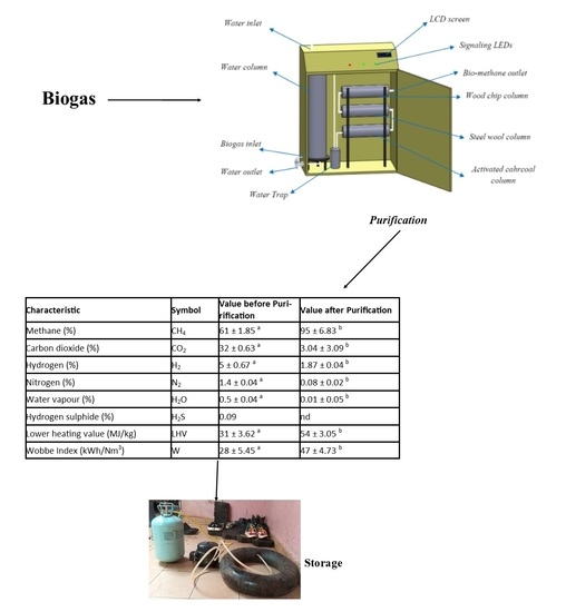
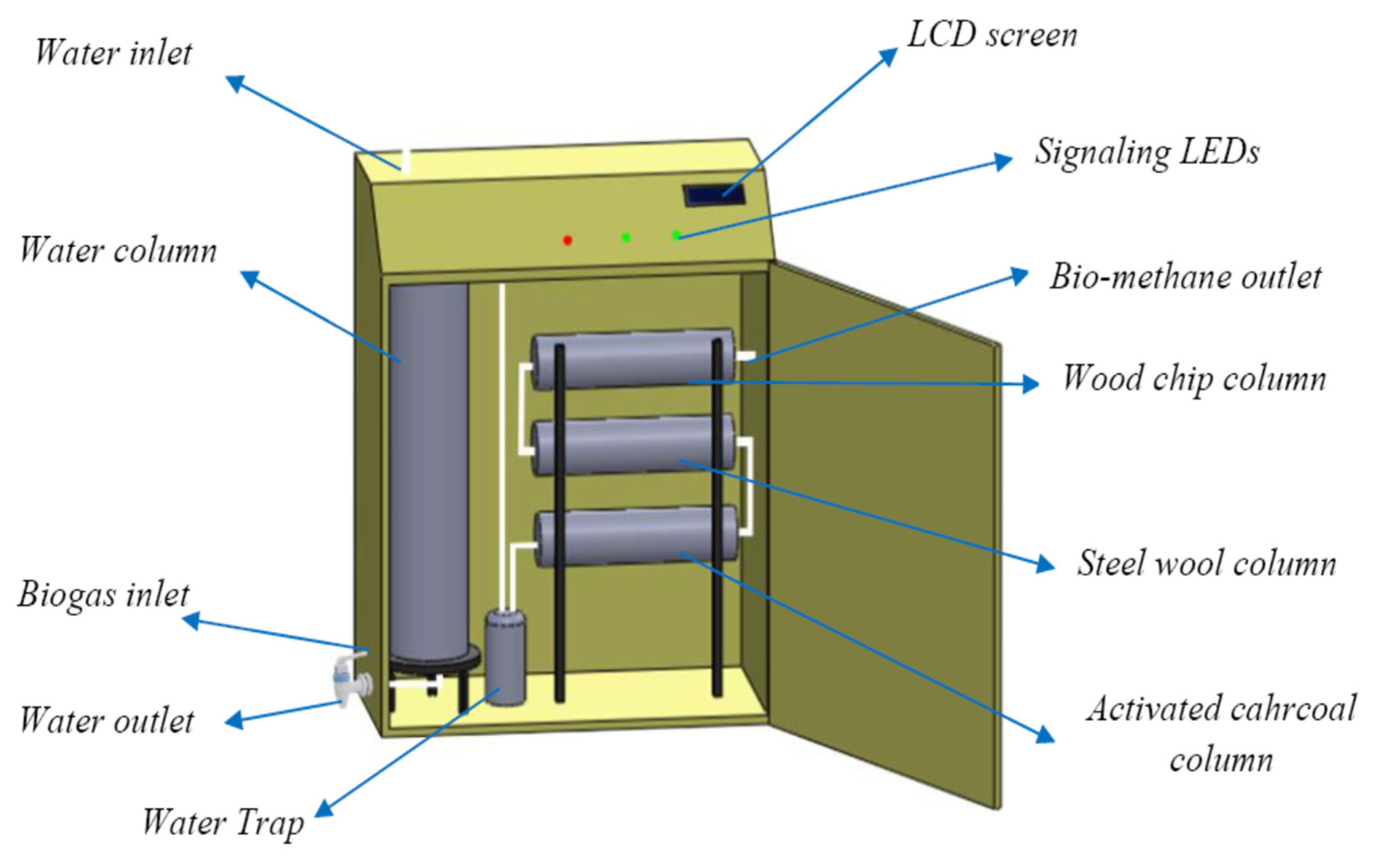
2.2. Biogas Purification

The purpose of the purification of biogas is to reduce its impurity content and obtain an enriched biomethane. The biogas purification device used and its operation was as follows. The raw biogas was transported from the biodigester to the purification system through a PVC pipe (110 EP: 3MM) buried in the ground, allowing the gas to cool. Then, it was first injected into a column containing water, where the CO2 was extracted by physical absorption. Then, the gas was passed into a transparent plastic bottle (for viewing) where the small quantities of water that was still found has been extracted (by condensation). Finally, the gas was passed through a succession of three columns containing: activated carbon, steel wool and wood chips. In these columns, H2S, VOCs, as well as those in a trace state, were extracted. Thus, the gas obtained at the outlet of the system was analysed for its purity using CP-3800 gas chromatograph (Agilent Technologies 7890B Wilmington, NC, USA). The system of purification of biogas is shown in Figure 1.
A device for piping and determination of biogas content was then installed. It was composed of a PVC pipe, a pressure hose, a non-return water valve, reducer and hydraulic fittings, valves and elbows, silicone, teflon for canalization, a methane sensor (MQ-04), a temperature sensor (LN35), an Arduino microcontroller (UNO), and an LCD display (1602A) for determination.

2.3. Chemical Analysis

Chemical analysis of the biomasses, as well as raw and purified biogas, was performed to evaluate total solid and volatile matter by using ASTM E1756-08 and E872-82 methods (Reapproved 2006), respectively. Elementary carbon and nitrogen from bio-masses were quantified by a high-resolution scanning electron microscope (SEM) (Make: Carl Zeiss, Model: LEO 1430 VP) with an attachment of energy dispersive X-ray (EDX) system (Make: Oxford, UK). The relative amounts of methane and carbon dioxides in the biogas were determined using the CP-3800 gas chromatograph. The instrument was first calibrated with reference gas containing a mixture of methane (45%) and carbon dioxide (45%). The injected mode of the chromatography was set using a computer aided program Galaxy Workstation. With the use of a manual syringe (MODEL PN5190 1503), 20 µm of gas was obtained from the biogas rubber tubbing and injected into the TC detector of CP-3800 chromatographer. This was performed twice a week and the chromatographic results recorded for the percentage of methane and carbon dioxide which set a base of qualitative analysis of the biogas. The calorific value of biomethane at the end of purification depends on that of pure methane and the methane content in the final gas, LHV, and electrical conductivity of purified biogas were determined by AOAC method [8].

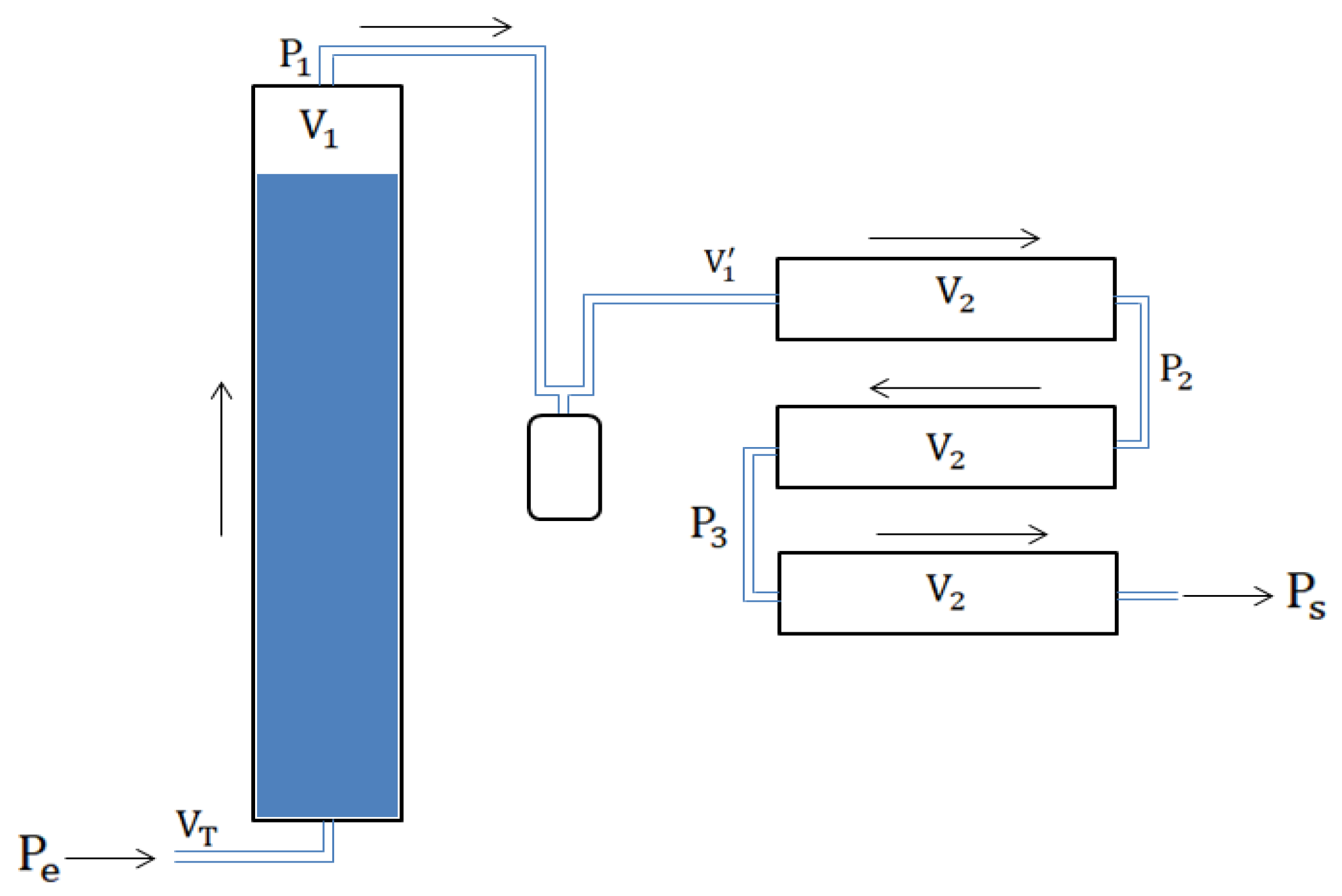
2.3.1. Estimation of the Pressure of the Biomethane at the Outlet of the System

It is necessary to know the pressure at the outlet of the purification system to be able to determine the volume of gas stored as a function of time. Figure 2 shows a two-dimensional view of the system with the different pressure points to be taken into account.
From the ideal gas equation (PV = nRT, stated by Amedeo Avogadro in 1811), in the water column, the following relationships were established:
  P 1 = n b   *   R   *   T V 1
Yet,
n b = n 0 n CO 2
With
n CO 2 = 0.27 n 0
Equations (1) and (2) in Equation (3) gives:
P 1 = 0.73 V T * P g V 1
The temperature was assumed to be constant throughout the system. The following relation can therefore be written:
P 1 * V 1 = P 2 * V 2
Likewise,
{ P 2 * V 1 = 2 P 3 * V 2                                                                               P 3 * V 1 = 2 P s * V 2                                                                              
Equations (1)–(5) therefore allow the expression of the pressure at the outlet of the system as a function of that at the inlet.
P s = 0 , 73 * V T 3 4000 V 1 * V 2 3 P g
With:
P ( g ) : Total pressure of the biogas (Pa);
V T : Volume of the biogas inlet piping (m3);
V 1 : Volume of gas in the water column (m3).
The MATLAB software made it possible to have in the results section, the curve giving the variations in the outlet pressure of the purification system and a function of that of the biogas inlet.

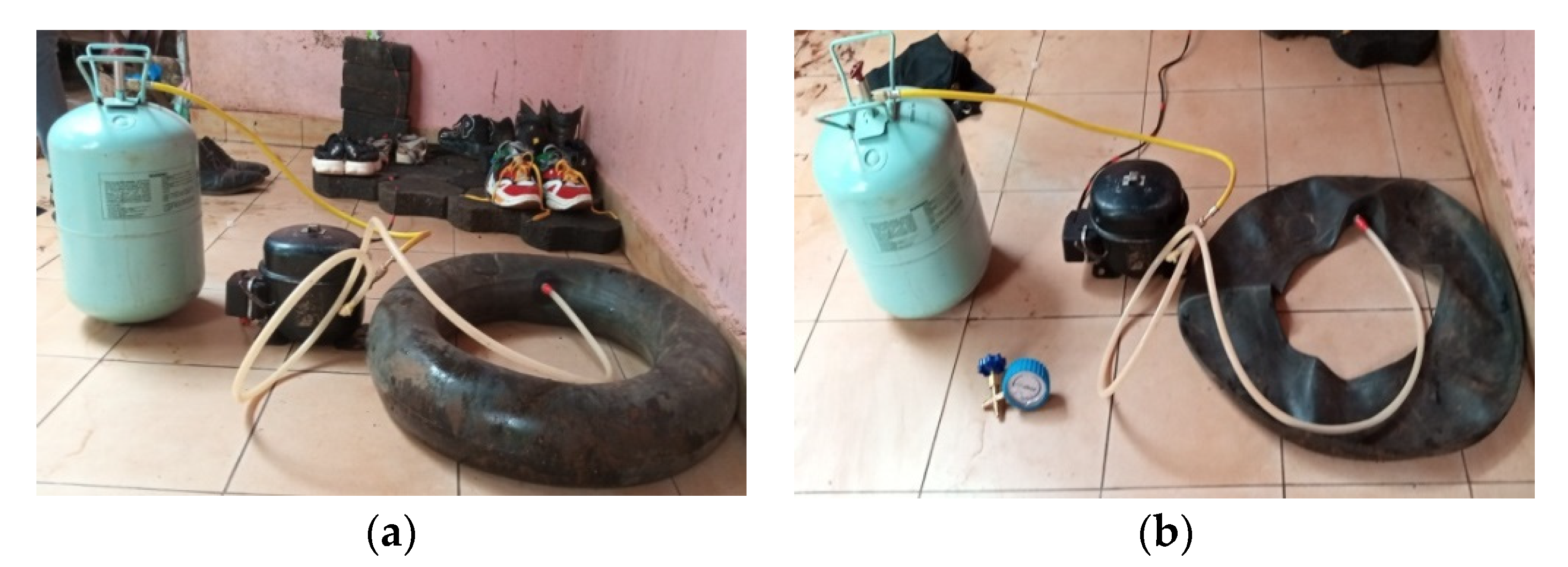
2.3.2. Biogas Storage in an Inflatable Balloon

The storage of biogas is the central part for the production of electricity or cooking according to demand. The imbalance between the production and consumption of biogas, especially on week-ends or in the dry season, prompted the establishment of a biogas purification and storage system. The objective was to add value to 100% of the production of a biodigester.
In the event of a congestion problem, therefore, the biogas was directed to our system or after being purified, and was then stored in an inflatable balloon or in a bottle depending on the quantity of gas.
Once out of the system, the purified gas was directed into an inflatable balloon for storage. The balloon could then be chosen according to the volume of daily biogas to be treated. In this case, the volume of the balloon is given by:
  V b = V gt ( V gm + η V gt )
With:
V b : Balloon volume (m3);
V gt : Volume of biogas to be treated (m3);
V gm : Total volume of dead gas in the system;
η: Efficiency of the purification system.

2.3.3. Storage by Compression in a Bottle

The bottle was used here when the flask is full and its contents are not ready for use. It allowed easy movement from one point to another with gas.
In the case of this work, the material chosen was easily accessible. For this, a refrigerator compressor was used to be able to compress the gas and an extinguisher cylinder as a storage medium for the compressed gas. In order to ensure the circulation of the purified biogas from the inflatable balloon to the bottle, a compressor was used which has the role of creating a low pressure on one side (for the gas suction) and a high pressure of the other side (so that gas can enter the bottle). The compressor was characterized by [9]. For that, aspirated volume, compression rate, volumetric efficiency, and compressor power were determined like following equations. The aspirated volume is the volume of gas actually sucked by the compressor.
V a =   q m * V m * 3600
With:
V a : Gas volume sucked (m3/h);
q m : Mass gas flow (kg/s);
V m : Specific volume (m3/kg).
Compression rate is the ratio between the discharge pressure and the suction pressure.
t c = P ref P asp
With:
tc: Compression rate; Pref: Discharge pressure; Pasp: Suction pressure
Volumetric efficiency is the ratio between the volume flow sucked in and the volume flow rate swept by the compressor. Its empirical formula is as follows:
η v = 1 ( 0.05 t c )
Since we have chosen to use a refrigerator compressor, compressor power represents the amount of energy absorbed by the refrigerant per unit of time.
Φ = q m * Δ h 3600
With: Φ: Compressor power; qm: mass flow (kg/h)

3. Results and Discussion

3.1. Characteristics of Lignocellulosic Biomasses in Sudano-Sahelian Context

The composition of the substrates used for the production of biogas is presented in Table 2. It appears from this table that total solids (TS) contents of all the substrates, except cow dung (20%), were between 85 and 90%. The C:N ratio varied between 33 and 87:1, excluding cow dung which is 22.644:1. These results are similar to those of Martikainen [5] for straw rice and rice husk. Mustankorkea et al. [7] demonstrated that the performance of biodigesters was better when the C:N ratio of the mixture was between 25 and 30:1 and the total solids of cow dung at 8%, because the microorganisms during the biomethanization used more quickly 25 to 30 times the carbon than the nitrogen. Okoro and Soleil [10,11] estimated that the total solids content of bovine excrements between 7.4 and 9.2% had the best digestibility performances. Naik et al. [12] estimated that the maximum biogas production was obtained when the total solids content and temperature were 8% and 35°C, respectively. From the characterization of the biomasses, it was observed that all the biomasses had a fairly good amount of volatiles in the range of 82–85%, indicating a fairly good potential to generate biogas. However, it was observed that volatile matters in the rice straw and rice husk samples were lower than those of Bil-bil and Arki residues. In this context, Bil-bil and Arki residues, straw, and rice husk were mixed with cow dung and water to obtain a C:N ratio was between 25 and 30:1, and a total solids content between 8 and 9%. For that, 25% dry biomass and 75% cow dung were mixed (300g) and water was added to the mixes in a 1:3 (m/v) ratio.
Table 3 gives the length, width, and depth necessary for the software design and practical realization of the box for the purification system, as well as the volumes of the various purification points and specific surface area of materials used for purification of biogas.

3.2. Composition of Biogas before and after Purification in Sudano-Sahelian Context

Upgradation of the biogas was performed using different methods. From the purification, Table 3 shows the experimental results and that the amount of methane available in the raw and purified biogas was approximately 61 ± 1.85% and 95 ± 6.83%, respectively. At the end of purification, it is important to characterize the biogas obtained in order to better determine these areas of use other than those of culinary needs. The biogas obtained has a biomethane content of approximately 95% and a calorific value of 54 MJ/kg. These results have, therefore, made it possible to extend the fields of use of bio-methane towards the production of electrical energy via a generator. Because, according to the ISO 15403 standard, the methane content in bio-NGV must be at least 86% to be used as engine fuel. Table 4 shows the composition of biogas before and after treatment. This table suggests that the combustible components of biogas are CH4 and H2 with 61 and 5% values and 95 and 1.87% values before and after purification, respectively. Among the elements that make up biogas, some have no energy input. They are unnecessary and sometimes toxic to the environment although their concentrations are low. Biomethane is in significant quantity and it is the major and energy-consuming compound of biogas.
According to Al-Imarah et al. [13], the biogas obtained from anaerobic digestion is most often directly introduced into the system and into the adsorption chamber, the H2S, of which the concentration is between 300 and 2500 ppm, and CO2 are absorbed by the water. Thus, H2S is released in the desorption process to be cleaned before being released into the atmosphere to avoid adverse effects on humans and the environment. The removal of hydrogen sulfide can also be carried out by adsorption with activated carbon, as we did. Hydrogen sulfide upon adding oxygen to the desorption chamber oxidizes to form sulfuric acid and elemental sulfur [13].
It appears from the Table 4 that all the impurities mentioned above were removed and biogas was upgraded to biomethane with the quality of natural gas quality, because the value of impurities contents have been greatly reduced H2O vapor, H2S, and N2 [13]. According to Arya et al. [14], obtaining a Wobbe Index (W) similar to that of household gas, the essential impurity to remove is carbon dioxide. Most often, the best biogas is 97 to 99% biomethane and 1 to 3% carbon dioxide for domestic use or as vehicle fuel, and the content for CO2 and N2 must be between 1.5 and 4.5%, while in pipelines the CO2 requirement is less than 3%.
From Sahota et al. [15], adsorption process is the adhesion of compounds onto a solid surface. When the product is flushed through an adsorbent bed, contaminant molecules will bind to the adsorbent’s surface, removing the contaminants from the gas stream. Raw biogas needs to be cleaned to remove toxic and harmful constituents (carbon dioxide, hydrogen sulfide, ammonia, moisture, siloxane, particulates, etc.) to meet regulatory and technical standards [16]. Our system, composed of water scrubbing and activated carbon, steel wool, and wood chips scrubbing, has provided a biofuel with interesting characteristics, in terms of LHV (54 MJ/kg) and W (47 kWh/Nm3).

3.3. Biomethane Storage in Sudano-Sahelian Context

3.3.1. Storage in the Balloon

The biomethane storage system used in this work was made of three units: a compressor, a pressure gauge, and an LPG cylinder after storage in balloon. Table 5 shows the characteristics of chosen balloon. The compressor used in this experience was a hermetic reciprocating type compressor used in the manufacture of commercial refrigerators with a hydrocarbon refrigerant. The pressure of the biogas at various points of compression could be indicated using a pressure gauge. For storing the biogas after compression, a normal LPG cylinder was used. The storage of biogas is a real problem, like all gaseous products [17]. According to Wilken et al. [18], biogas could not be stored easily, as it does not liquefy at ambient temperature under pressure. According to the same author, its critical temperature and pressure are −82.5 °C and 47.5 bar. Compressing the biogas reduces the storage requirements, offers concentrated energy content, and gives pressure to overcome the resistance to gas flow [19]. A car inner tube was used to store the produced biomethane in order to study the filling of the inner tube as a function of time.

3.3.2. Storage by Compression in a Bottle

It has been shown by the IEA [20] that the work and the cost of the compressor increase by the power of the pressure differences. Thus, the greater the pressure differences were, the greater the energy consumption was. The networks of existing gas production system determine the design of the compressor and, therefore, the biomethane pressure (head pressure) and the gas upgrading process (inlet pressure), as applied through Equations (9) to (12).

Compressor Characteristics

After study, the choice of a refrigerator compressor turned out to be better, due to its availability and affordable cost [21]. Table 6 shows the characteristics of the chosen compressor. Biogas is not typically produced at the time it is needed or in the quantity needed to satisfy the conversion system load that it serves [22]. Therefore, compression and storage of biogas is a necessity in order to smooth out variations in gas production, gas quality, and gas consumption [23,24]. The storage component also acts as a reservoir, allowing downstream equipment to operate at a constant pressure [25,26]. Finally, the purified and upgraded biogas could be compressed into an liquefied biogas cylinder by using a refrigerant reciprocating compressor up to an absolute pressure of 25 bars in a total of 12–14 min.
After storage in a car inner tube, the biomethane was compressed in a bottle of R134a (refrigerant gas), as shown in Figure 3.

Bottle Characteristics

For long-term and more secure storage, it was best to choose a cylinder with a copper-coated interior. The various tests were carried out with a bottle of R134a, the characteristics of which are shown in Table 7.
This section may be divided by subheadings. It should provide a concise and precise description of the experimental results, their interpretation, as well as the experimental conclusions that can be drawn.

4. Conclusions

The production of biogas is impacted by the economic factor. The profitability of biogas production facilities has increased due to its increasing use in several sectors, such as heat production and its use as a biofuel. The numerous technological improvements for upgrading biogas into biomethane could increase performance in terms of cost and would make this fuel competitive.
Raw biogas needs to be cleaned to remove harmful and toxic constituents (carbon dioxide, hydrogen sulfide, halides, ammonia, moisture, siloxane, particulates, etc.) to meet regulatory and technical standards. The principle cleaning techniques that are currently used include adsorption, biofiltration, water scrubbing (an absorption process), and refrigeration.
The goal of this study was to design and implement a biogas purification and storage system for energy recovery from biomethane. This is in order to take advantage of the excess biogas at the individual level of certain users who have a biodigester. To achieve this goal, three main steps were developed.
Traces of impurities are present in biogas. Removal of these impurities (such as water vapor, CO2, and H2S) is essential prior to using as biofuel for various applications. We have established the setup required for the purification and compression. The biogas obtained has a biomethane content of approximately 65%. After upgrading, it reached 95 % for a calorific value of 54 MJ/kg. This work suggests that the combustible components of biogas are CH4 and H2 with 61 and 5% values and 95 and 1.87% values before and after purification, respectively. Compressing the biogas reduces the storage requirements, offers concentrated energy content, gives a better flow, and simplifies transportation due to reduced volume handling. Then, the biomethane obtained is stored in an inflatable balloon and then in a bottle by compressing the gas contained in the balloon. These results show that it is possible to extend the fields of use of biomethane towards the production of electrical energy via a generator.

Author Contributions

Conceptualization, D. and H.B.; methodology, D. and H.B.; software, G.C.; validation, D. and P.M.; formal analysis, D., H.F.; Investigation, H.F. and L.J.M.N.; resources, D. and G.C.; data curation, L.J.M.N.; writing—original draft preparation, D. and H.B.; writing—review and editing, D. and G.C.; supervision, P.M. and G.C.; project administration, D. and P.M.; funding acquisition, D. All authors have read and agreed to the published version of the manuscript.

Funding

This research received no external funding.

Institutional Review Board Statement

Not applicable.

Informed Consent Statement

Not applicable.

Data Availability Statement

Not applicable.

Acknowledgments

This work was carried out with the help of the Center for International Cooperation in Agronomic Research for Development (CIRAD) in Montpellier/France and the Inter-establishment Agency for Research for Development (AIRD).

Conflicts of Interest

The authors declare no conflict of interest.

References

  1. BP Statistical Review of World Energy. Centre for Energy Economics Research and Policy, Heriot-Watt University. 2019, p. 64. Available online: Ceerp.hw.ac.uk (accessed on 5 September 2021).
  2. Ghasemian, S.; Faridzad, A.; Abbaszadeh, P.; Taklif, A.; Ghasemi, A.; Hafezi, R. An overview of global energy scenarios by 2040: Identifying the driving forces using cross-impact analysis method. Int. J. Environ. Sci. Technol. 2020, 1–24. [Google Scholar] [CrossRef]
  3. Scarlat, N.; Dallemand, J.; Fahl, F. Biogas: Development and perspectives in Europe. Renew. Energy 2020, 129, 457–472. [Google Scholar] [CrossRef]
  4. Herbes, C.; Halbherr, V.; Braun, L. Factors influencing prices for heat from biogas plants. Appl. Energy 2018, 221, 308–318. [Google Scholar] [CrossRef]
  5. Martikainen, E. Mustankorkea Oy—Biological Waste Treatment and Making Products (and Profit) out of It; Mustankorkea: Laauka, Finland, 2018. [Google Scholar]
  6. Kapoor, R.; Ghosh, P.; Kumar, M.; Vijay, V.K. Evaluation of biogas upgrading technologies and future perspectives: A review. Environ. Sci. Pollut. Res. 2019, 26, 11631–11661. [Google Scholar] [CrossRef]
  7. Mustankorkea Oy, J.; Merkle, W.; Baer, K.; Haag, N.L.; Zielonka, S.; Ortloff, F.; Graf, F.; Lemmer, A. High-pressure anaerobic digestion up to 100 bar: Influence of initial pressure on production kinetics and specific methane yields. Environ. Technol. 2017, 38, 337–344. [Google Scholar]
  8. AOAC. Official Methods of Analysis of the Association of Official Analytical Chemists; AOAC: Washington, DC, USA, 2000. [Google Scholar]
  9. The Biogaz Handbook. In Sciences, Production and Applications; Woodheat Publishing Series in Energy; Eds Arthur Wellinger and Co., Woodhead: Cambridge, UK, 2013.
  10. Mrosso, R.; Machunda, R.; Pogrebnaya, T. Removal of Hydrogen Sulphide from Biogas Using a Red Rock. Hindawi J. Energy 2020, 2020, 2309378. [Google Scholar]
  11. Okoro, O.; Sun, Z. Desulphurisation of Biogas: A Systematic Qualitative and Economic-Based Quantitative Review of Alternative Strategies. Chem. Eng. 2019, 3, 76. [Google Scholar] [CrossRef] [Green Version]
  12. Naik, L.; Gebreegziabher, Z.; Tumwesige, V.; Balana, B.B.; Mwirigi, J.; Austin, G. Factors determining the stability and productivity of small scale anaerobic digesters. Biomass Bioenergy 2014, 70, 51–57. [Google Scholar] [CrossRef]
  13. Al-Imarah, K.A.; Lafta, T.M.; Jabr, A.K.; Mohammad, A.N. Desulphurization for Biogas Gen-erated by Lab Anaerobic Digestion Unit. IOSR J. Agric. Vet. Sci. 2017, 10, 66–73. [Google Scholar]
  14. Arya, A.; Divekar, S.; Rawat, R.; Gupta, P.; Garg, M.O.; Dasgupta, S.; Nanoti, A.; Singh, R.; Xiao, P.; Webley, P.A. Upgrading Biogas at Low Pressure by Vacuum Swing Adsorption. Ind. Eng. Chem. Res. 2015, 54, 404–413. [Google Scholar] [CrossRef]
  15. Sahota, S.; Shah, G.; Ghosh, P.; Kapoor, R.; Sengupta, S.; Sing, P.; Vijay, V.; Sahay, A.; Vijay, V.K.; Thakur, I.S. Bioresource Technology Reports; Elsevier: Amsterdam, The Netherlands, 2018; Volume 1, pp. 79–88. [Google Scholar]
  16. Santos-Clotas, E.; Cabrera-Codony, A.; Castillo, A.; Martín, M.J.; Poch, M.; Monclús, H. En-vironmental decision support system for biogas upgrading to feasible fuel. Energies 2019, 12, 1546. [Google Scholar] [CrossRef] [Green Version]
  17. Sarker, S.; Lamb, J.J.; Hjelme, D.R.; Lien, K.M. Overview of Recent Progress Towards In-situ Biogas Upgrading Techniques. Fuel 2018, 226, 686–697. [Google Scholar] [CrossRef]
  18. Wilken, D.; Strippel, F.; Hofmann, F.; Maciejczyk, M.; Klinkmüller, L.; Wagner, L.; Bontempo, G.; Münch, J.; Scheidl, S.; Conton, M.; et al. Bio-Gas to Biomethane; Fachverband Biogas e. V: Bonn, Germany, 2017. [Google Scholar]
  19. Ohannessian, A. Composés Organiques Volatils du Silicium: Un Frein à la Valorisation Énergétique des Biogaz: “Genèse et Mécanismes de Formation”. Ph.D. Thesis, INSA de Lyon, Villeurbanne, France, 4 December 2018; p. 244. [Google Scholar]
  20. IEA. Outlook for Biogas and Biomethane: Prospects for Organic Growth. 2020. Available online: https://www.iea.org/reports/outlook-for-biogas-and-biomethane-prospects-for-organic-growth/sustainable-supply-potential-and-costs (accessed on 23 July 2020).
  21. Shen, Y.; Linville, J.L.; Urgun-Demirtas, M.; Schoene, R.P.; Snyder, S.W. Producing pipe line quality biomethane via anaerobic digestion of sludge amended with corn Stover biochar with in-situ CO2 removal. Appl. Energy 2015, 158, 300–309. [Google Scholar] [CrossRef] [Green Version]
  22. Brauman, A.; Fonty, G.; Roger, P. La méthanisation dans les écosystèmes Naturels et cultivés. In Moletta, R. La Méthanisation; Editions Tec & Doc. Paris: Lavoisier, France, 2008; pp. 9–59. [Google Scholar]
  23. Wedraogo Tarsida, N. Valorisation du Biogaz par Purification et par Reformage. Ph.D. Thesis, Génie des Procédés et des Produits. NNT, Lorraine, France, 2018; p. 201. [Google Scholar]
  24. Abanades, S.; Abbaspour, H.; Ahmadi, A.; Das, B.; Ehyaei, M.A.; Esmaeilion, F.; Assad, M.E.; Hajilounezhad, T.; Jamali, D.H.; Hmida, A.; et al. A critical review of biogas production and usage with legislations framework across the globe. Int. J. Environ. Sci. Technol. 2021, 1–24. [Google Scholar] [CrossRef]
  25. Wang, T.; Shao, L.; Li, T.; Lü, F.; He, P. Digestion and dewatering characteristics of waste activated sludge treated by an anaerobic biofilm system. Bioresour. Technol. 2014, 153, 131–136. [Google Scholar] [CrossRef]
  26. Angelidaki, I.; Treu, L.; Tsapekos, P.; Luo, G.; Campanaro, S.; Wenzel, H.; Kougias, P.G. Biogas upgrading and utilization: Current status and perspectives. Biotechnol. Adv. 2018, 36, 452–466. [Google Scholar] [CrossRef] [Green Version]
Figure 1. Complete diagram of the purification system.
Energies 14 05855 g001
Figure 2. 2D view of the purification system.
Energies 14 05855 g002
Figure 3. Compression of biomethane (a) full and (b) empty balloon.
Energies 14 05855 g003
Table 1. Characteristics of the biodigester.
ElementsUnitsCharacteristic
Type -Borosilicate glass
Nature of the substrate-Mixed waste
Gas productionm3/day0.05
Digester volumem30.01
Pre-treatment tank volumem30.25
Volume of discharge tank m30.02
Table 2. Composition of lignocellulosic biomasses (Dry weight basis).
Characteristics (%)Bil-Bil ResidueArki ResidueStraw RiceRice HusksCattle Dung
Total solid 87.0 ± 3.786.4 ± 2.585.7 ± 4.286.8 ± 3.787.0 ± 3.7
Volatile compounds84.0 ± 4.083.0 ± 5.266.2 ± 2.878.0 ± 4.184.0 ± 4.0
Carbon56.8 ± 2.958.0 ± 0.834.5 ± 5.134.8 ± 8.256.8 ± 2.9
Notrigen0.732 ± 0.0230.662 ± 0.0541.023 ± 0.0930.504 ± 0.0270.732 ± 0.023
* C:N before mixing77.6 ± 7.287.7 ± 6.033.7 ± 4.769.1 ± 0.0377.6 ± 7.2
** C:N after mixing27.8 ± 4.728.5 ± 3.023.5 ± 5.727.2 ± 0.827.8 ± 4.7
* Before mixing with Cattle dung, ** after mixing with Cattle dung.
Table 3. Dimensions and capacities of purification system.
ElementsUnitsValue
Lengthm105 × 10−2
Width m75 × 10−2
Depth m35 × 10−2
Screen tiltm14 × 10−2
Water tank column volumem310−2
Activated charcoal column volumem310−3
Steel wool storage volumem310−3
Specific surface area charcoal (BET)m2/g231.02
Specific surface area steel wool (BET)m2/g343.528
Table 4. Biogas composition before and after purification.
CharacteristicSymbolValue before PuririficationValue after Purification
Methane (%)CH461 ± 1.85 a95 ± 6.83 b
Carbon dioxide (%)CO232 ± 0.63 a3.04 ± 3.09 b
Hydrogen (%)H25 ± 0.67 a1.87 ± 0.04 b
Nitrogen (%)N21.4 ± 0.04 a0.08 ± 0.02 b
Water vapour (%)H2O0.5 ± 0.04 a0.01 ± 0.05 b
Hydrogen sulphide (%)H2S0.09nd
Lower heating value (MJ/kg)LHV31 ± 3.62 a54 ± 3.05 b
Wobbe Index (kWh/Nm3)W28 ± 5.45 a47 ± 4.73 b
The results having the same letters in exponent on the same column are not significantly different (probability threshold p ≤ 0.05).
Table 5. Characteristics of the chosen balloon.
ElementsUnitsValue
Total volume of the balloonm33
Balloon lengthm1.5
Balloon widthm1.5
Balloon heightm1
Material-Rubber
Table 6. Characteristics of the chosen compressor.
ElementsUnitsValue
Generated power HP1/8
Power supplyW97
Sucked gas flowm/s0.17 × 10−3
maximum pressure allowed Bar25
Table 7. Characteristics of the bottle.
ElementsUnitsValue
VolumeL13.4 × 10−3
Working pressureBar28
Filling capacitykg13.6
Critical pressureBar40.7
Critical temperature°C101.1
Publisher’s Note: MDPI stays neutral with regard to jurisdictional claims in published maps and institutional affiliations.

