Article

Dynamic Influence of Wheel Flat on Fatigue Life of the Traction Motor Bearing in Vibration Environment of a Locomotive

1
State Key Laboratory of Heavy Duty AC Drive Electric Locomotive Systems Integration, Zhuzhou 412001, China
2
CRRC Zhuzhou Locomotive Co., Ltd., Zhuzhou 412001, China
3
State Key Laboratory of Traction Power, Southwest Jiaotong University, Chengdu 610031, China
*
Author to whom correspondence should be addressed.
Energies 2021, 14(18), 5810; https://doi.org/10.3390/en14185810
Submission received: 14 July 2021 / Revised: 2 September 2021 / Accepted: 10 September 2021 / Published: 14 September 2021

Abstract

:
Wheel flat can cause a large impact between the wheel and rail and excites a forced vibration in the locomotive and track structure systems. The working conditions and fatigue life of the motor bearings are significantly affected by the intensified wheel–rail interaction via the transmission path of the gear mesh. In this study, a fatigue life prediction method of the traction motor bearings in a locomotive is proposed. Based on the L−P theory or ISO 281 combined with the Miner linear damage theory and vehicle–track coupled dynamics, the irregular loads induced by the track random irregularity and gear mesh are considered in this proposed method. It can greatly increase the accuracy of predictions compared with the traditional prediction models of a rolling bearing life whose bearing loads are assumed to be constant. The results indicate that the periodic impact forces and larger mesh forces caused by the wheel flat will reduce the fatigue life of the motor bearings, especially when the flat length is larger than 30 mm. Using this method, the effects of the flat length and relatively constant velocity of the locomotive are analyzed. The proposed method can provide a theoretical basis to guarantee safe and reliable working for motor bearings.

1. Introduction

Wheel flat is a typical form of wheel tread failure, which continually occurs during the operation process of a high−power locomotive, owing to the emergency braking and skidding phenomenon of the wheelset. The larger periodic impact forces induced by the wheel flat can intensify the system vibrations, cause failure and fatigue damage of the components in a locomotive, such as the traction motor bearings, and even endanger the locomotive and track structure systems [1].
Previous investigations on this topic have focused on the wheel–rail interaction and the effect of wheel flat on the dynamic behaviors of the vehicle/track structure. Dong et al. [2] analyzed the dynamic effect of the wheel flat on the track structure through a finite element model. The simulation results indicate that the axle load and running speed of the vehicle are the major factors for the wheel–rail interaction under flat fault. Considering the partial and asymmetric contact at the wheel–rail interface generated by the wheel flat, Zhu et al. [3] proposed an adaptive wheel–rail contact model, which is verified by comparison with the proposed model with test data. Uzzal et al. [1] indicated that the dynamic responses of the vehicle and track structure systems are significantly affected by the haversine wheel flat, except the car body, owing to the damping effect of the secondary suspensions. Steenbergen [4] analyzed the contact geometry between the wheel flat and rail. Bian et al. [5] investigated the wheel–rail contact status with a wheel flat via the established three−dimensional finite element model. Zhou et al. [6] proposed a fault diagnosis method for the wheel flat based on the electromechanically coupled effect. A co-simulation locomotive dynamics model with the electrical drive system was established to identify the fault feature of the wheel flat via the analysis of the electrical signals.
The dynamic behaviors of the motor bearing easily receive the effect of periodic wheel flat−rail impact forces via the transmission path of gear mesh in a locomotive. It is the key aspect to obtain the dynamic loads for a fatigue life prediction of the motor bearing. Fortunately, previous investigations make it possible to analyze the dynamic behaviors of the motor bearings in the vibration environment under the complex wheel–rail interactive forces. Zhai and Sun [7] proposed the typical vehicle−track coupled dynamics model in which the vehicle and track are regarded as a coupled system via the wheel–rail interaction, namely the Zhai model. Chen et al. [8] further considered the power transmission path of the locomotive and developed a locomotive−track coupled dynamics model with gear transmissions to research the dynamic responses of the gear transmissions and the influence of the tooth root crack on the whole coupled system. Liu et al. [9,10,11] and Wang et al. [12], respectively, analyzed the dynamic and thermal characteristics of the motor bearings in the vibration environment of a locomotive or a high−speed train.
Rolling bearings are widely used in rotating equipment; however, the dynamic loads induced by the complex working conditions can shorten their service lives. The fatigue life prediction for the rolling bearing has attracted many scholars and researchers around the world, which is used to guarantee the safety and reliability of equipment operation. Based on the Hertz contact theory and Weibull distribution, Lundberg and Palmgren [13,14] proposed a prediction method for fatigue life of a rolling bearing (L−P theory). However, the influences of lubrication, contamination, and temperature are ignored. According to a statistical relationship among the probability of survival, fatigue life, and stress−related fatigue criteria level beyond the fatigue limit, Ioannides and Harris [15] proposed a new rolling bearing fatigue life prediction model (I−H theory). Zhang et al. [16] established a dynamics model of the angular contact ball bearing, in which the centrifugal forces and gyroscopic moments are considered. It concluded that the load distribution and fatigue life of bearing would be improved significantly by a proper preload. Londhe et al. [17] discussed the effect of variation of elastic modulus due to the case hardening on the subsurface stress and bearing fatigue life. Gupta and Zaretsky [18] first proposed a stress−based life model for the rolling bearing according to the dynamic stress capacity. Jouini et al. [19] analyzed the effect of machined surface integrity on fatigue life of the bearing rings ground on the experimental results.
Based on the descriptions above, the service conditions of the motor bearings are especially complicated under the simultaneous effect of the gear mesh force, internal dynamic forces of the traction motor, and environmental vibration of the locomotive. However, the present fatigue life prediction method based on the constant load [13,14,20] cannot reflect the actual working conditions of rolling bearings. In addition, due to the complicated unpredicted excitations induced by the track random irregularity and time−varying mesh stiffness, the dynamic responses of the motor bearings cannot be obtained via the analytic method. Therefore, it is essential to investigate the instantaneous fatigue damage of the motor bearing considering the effect of time−varying loads based on the dynamic simulation and further prediction of its reliable service life.
In this study, the effect of wheel flat on the dynamic responses of the motor bearings has been explored via incorporating the time−varying displacement excitation induced by the wheel flat into the locomotive−track coupled dynamics model (LTM). In addition, based on L−P theory and ISO 281, combined with the Miner linear damage theory, a life prediction method for the rolling bearing fatigue is employed to investigate the fatigue life of the motor bearing under the wheel flat−rail interaction and gear mesh. The results of the analysis can reflect the damage of the wheel flat on the operational reliability for the traction power transmission of the locomotive.

2. Dynamic Model Formulation

Comparing with the fixed equipment (e.g., machine tools, turbine, and so on), the working conditions of components in railway vehicles are sensitive to the intensified wheel–rail interaction induced by the track random irregularity, which will be aggravated by some defects generated on the wheel and rail (e.g., wheel flat, wheel polygonization, rail undulatory wear, etc.). Meanwhile, the gear mesh generates large dynamic mesh forces in the course of the operating of a locomotive. These dynamic loads will exacerbate the working condition and reduce the service life of the motor bearing. Therefore, it is essential to study the dynamic behaviors and fatigue life of the motor bearing in the vibration environment considering the influence of the wheel flat.

2.1. LTM

To analyze the effect of wheel flat on the vehicle vibration and gear transmission and obtain the accurate dynamic load acting on the motor bearings, an LTM developed by Liu et al. [9] is employed in this study, which is shown in Figure 1. In this model, the non−linear wheel–rail interaction, gear mesh, and internal interactions of the motor bearings are comprehensively considered. The coupled system is considered as a multi−rigid−body system. The mass and moment of inertia of components are assigned to their respective gravity centers. The wheel–rail interaction acts as a bridge in the coupling relationship between the vehicle and track structure subsystems. The connections between the components of this coupled system are represented as spring–damper elements.
As depicted in Figure 1, the car body and bogie frames are supported via the secondary (Ksz, Csz) and primary (Kpz, Cpz) suspensions, respectively. The axle box bearings are employed to connect the wheelset and axle box. The motor and gearcase are rigidly connected by bolted joints, and they are hung on the bogie through the hanger rod (Kms, Cms). Additionally, the pull rods between the bogie frame and car body, as well as the axle box, are represented as spring–damper elements (Ksr, Csr, Kpx, Cpx). The traction torque is transferred to the wheel–rail interface through the gear engagement, and the corresponding creep forces, which can drive the locomotive in longitudinal motion via the traction rods and overcome the running resistance, are generated. In this model, the mechanical structures for both the traction motor and its support bearings are considered. The motor bearings are installed between the rotor and motor to reduce the friction effect and ensure traction efficiency. The inner and outer rings are rigidly connected with the rotor and motor. Therefore, the time−varying mesh force and internal dynamic forces of the traction motor directly act on the motor bearings which will reflect complex dynamic characteristics. In the track structure subsystem, a typical ballasted track structure is adopted in this study. The flexibility of the rail is described by Euler’s beam model, and the elasticity and damping of the components of the track structure (e.g., the rail pad, ballast, and subgrade) are represented by a series of discrete spring–damper elements (Kp, Cp, Kb, Cb, Kf, Cf). To avoid repetition, the detailed dynamic equations of this coupled system can be obtained from our previous published research [9,21,22].

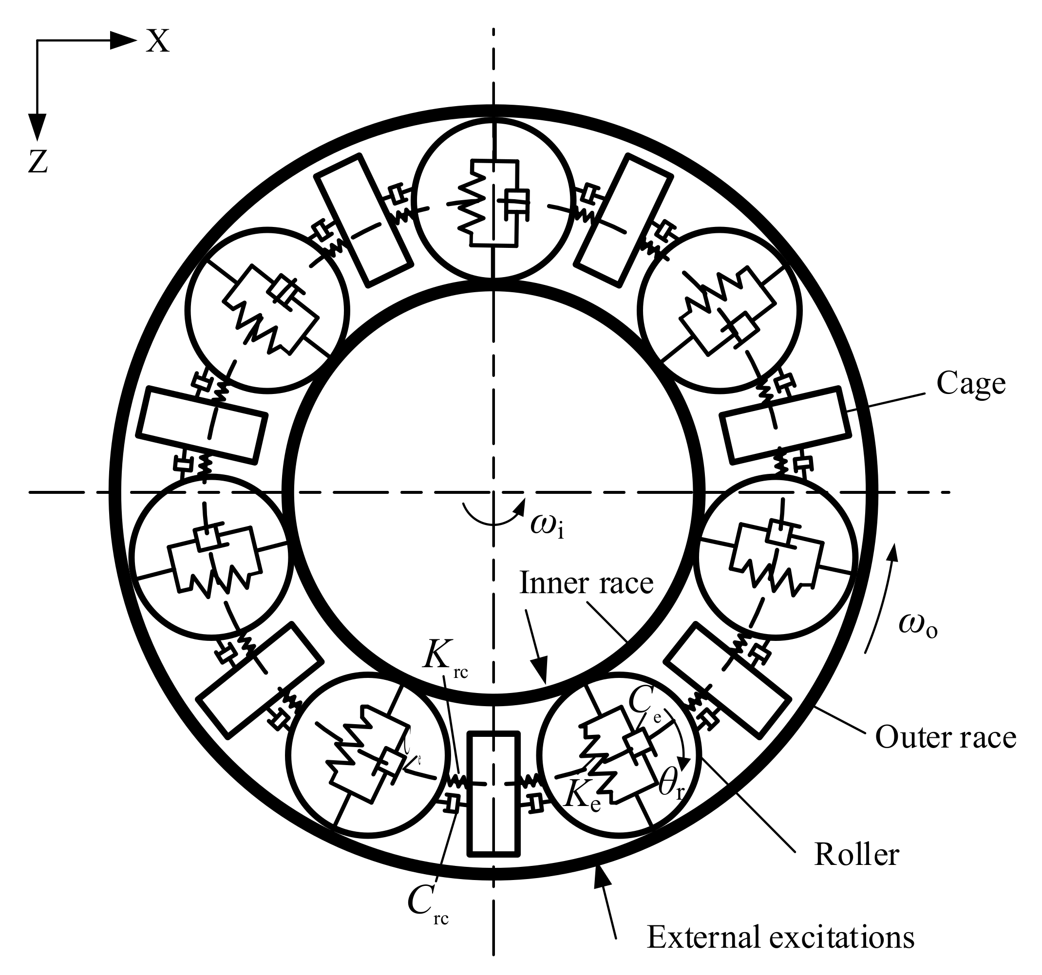
2.2. Dynamics Modeling of Rolling Bearing

Under the influence of external radial loads, the elastic deformations generate at the roller−race contact surface. The rotational and circumferential motions of the roller are driven by the inner ring via the friction effect between the roller and race. Besides, the cage is adopted to separate rollers and maintain their circumferential motions, which is driven by rollers in the loaded region while an opposite phenomenon will occur in the unloaded region. The schematic of a dynamics model of the rolling bearing is demonstrated in Figure 2, where the contacts between the components of the bearing are represented as spring–damper elements. In this model, the roller−race contact forces and corresponding friction forces, the relative slip, and the time−varying friction coefficient are comprehensively considered.
Because the inner and outer rings are fixed on the rotor and motor, their motions are consistent with those of the connected components of the traction motor. Therefore, the equations of motion for the roller and cage are formulated as
m r R m 2 σ ¨ r j R m N c j + F i j F o j m r g sin σ j = 0 , j = 1 , 2 , , N b
I r θ ¨ r j R r F i j + F o j F c j = 0 , j = 1 , 2 , , N b
I c σ ¨ c R m j = 1 N b N c j = 0 , j = 1 , 2 , , N b
where m and I are the mass and moments of inertia, respectively; θ and σ are, respectively, the rotational motion and circumferential motions; and the subscript r and c denote the roller and cage, respectively. Additionally, the subscript j is the serial number of the roller; Rr and Rm are the roller and pitch radii, respectively; g indicates the gravitational constant; σj = σrj + 2π × (j − 1)/Nb; Nb is the number of rollers; Nc is the contact force between the roller and cage; and Fi, Fo, and Fc are the friction forces between the roller and inner/outer races as well as the cage, which can, respectively, be calculated as
F i j = μ χ j K e δ j n Δ V i j Δ V i j , j = 1 , 2 , , N b
F o j = μ χ j K e δ j n + m r σ ˙ r j 2 R m Δ V o j Δ V o j , ( j = 1 , 2 , , N b )
F c j = μ c N c j = μ c K c σ r j σ c + C c σ ˙ r j σ ˙ c , ( j = 1 , 2 , , N b )
where Kc and Cc are the roller−cage contact stiffness and damping, respectively; μc is the roller−cage friction coefficient; Ke is the equivalent contact stiffness between the races via the roller; n donates the coefficient of load deformation; μ is the lubricant friction coefficient, which can be described as
μ = a + b Δ V e c Δ V i / o + d
where the values of coefficients a, b, c, and d are derived from the key parameters of the test value [23]. ΔVi/o are the relative slip velocities between the roller and inner/outer races, which can, respectively, be calculated as
Δ V i = ω i R i σ ˙ r R i θ ˙ r R r
Δ V o = σ ˙ r R o θ ˙ r R r ω o R o
where ω and R are the rotational velocities and radii, respectively; the subscript i and o denote the inner and outer races [24].
Moreover, the load zone parameter χj is described as
χ j = 1 ,   δ j 0 0 ,   δ j < 0
where δj is the relative radial displacement between the inner and outer races at the angular position of the jth roller, which can be expressed as
δ j = Z sin σ j + X cos σ j e 2 , j = 1 , 2 , , N b
where X and Z, respectively, are the relative displacements in longitudinal and vertical directions between the races of bearing; and e is the radial clearance.
Considering the influence of the centrifugal force of the roller, there is a minute difference between the roller−inner/outer races contact forces. For transmitting the mechanical vibrations between the rotor and motor, the resultant forces of the rolling bearing can be expressed as
{ F ix = j = 1 N b ( χ j K e δ j n sin σ j + μ χ j K e δ j n cos σ j ) F iz = j = 1 N b ( χ j K e δ j n cos σ j μ χ j K e δ j n sin σ j ) F ox = j = 1 N b [ ( χ j K e δ j n + m r σ ˙ r j 2 R m ) sin σ j + μ ( χ j K e δ j n + m r σ ˙ r j 2 R m ) cos σ j ] F oz = j = 1 N b [ ( χ j K e δ j n + m r σ ˙ r j 2 R m ) cos σ j μ ( χ j K e δ j n + m r σ ˙ r j 2 R m ) sin σ j ]
where the subscripts i and o indicate the resultant force generated from roller−inner/outer race interface, respectively; the subscript x and z indicate the longitudinal and vertical directions for the locomotive−track coupled system, respectively.
The roller−races contact forces in Equations (4)–(12) are given as
N i j N o j = χ j K e δ j n χ j K e δ j n + m r σ ˙ r j 2 R m , j = 1 , 2 , , N b
where N represents the contact forces [25,26].

2.3. Mesh Forces of Gear Transmission

The single−stage spur gear transmission is widely employed in gear transmissions in locomotives [8,9,10,11,12,21,22,27]. The traction torque generated from the traction motor is transmitted to the wheel–rail interface via the flexible teeth deformation of the gear pair along the line of action which is represented by a spring–damper element (Km, Cm). Under the effect of the intensified wheel–rail interactions, especially considering the wheel flat and other defects, the forward− and backward−side contacts may occur.
As shown in Figure 3, the mesh force of the gear pair can be expressed as,
F m = K mf δ + C mf δ ˙ for   forward - side   contact 0 for   contact   loss K mb δ + C mb δ ˙ for   backward - side   contact
where δ is the dynamic transmission error [8], which can be calculated as
δ i = R p β p i R g β g i + 1 i Z p i Z g i cos α 0 1 i X p i X p i sin α 0 b 0 e i for   forward - side   contact R p β p i R g β g i + 1 i Z p i Z g i cos α 0 1 i X p i X p i sin α 0 + b 0 + e i for   backward - side   contact , i = 1 , 2 , 3 , 4
where subscripts p and g indicate the pinion and gear of the gear transmission, respectively; R is the base circle radius; X and Z are the displacements in the longitudinal and vertical directions of the pinion/gear, respectively; α0 is the pressure angle of the gear pair; and b0 and e are the clearance errors and manufacture and assembly errors of the gear transmissions, respectively.
Considering the effect of tooth profile deviations, an improved calculation method of time−varying mesh stiffness for spur gear pair proposed by Chen et al. [28,29] is adopted, which can be calculated by
K m = K 1 + K 2 K 1 K 2 1 / K 12 + 1 / K 21 1 + K 2 E ˜ 12 1 K 1 / K 12 / F K 1 K 2 / K 12 K 21
The mesh stiffness of the single tooth pair is calculated by
1 K i = 1 K ap i + 1 K bp i + 1 K sp i + 1 K ag i + 1 K bg i + 1 K sg i + 1 K fp i + 1 K fg i + 1 K h i , ( i = 1 , 2 )
where the description of notations can be found in [28].

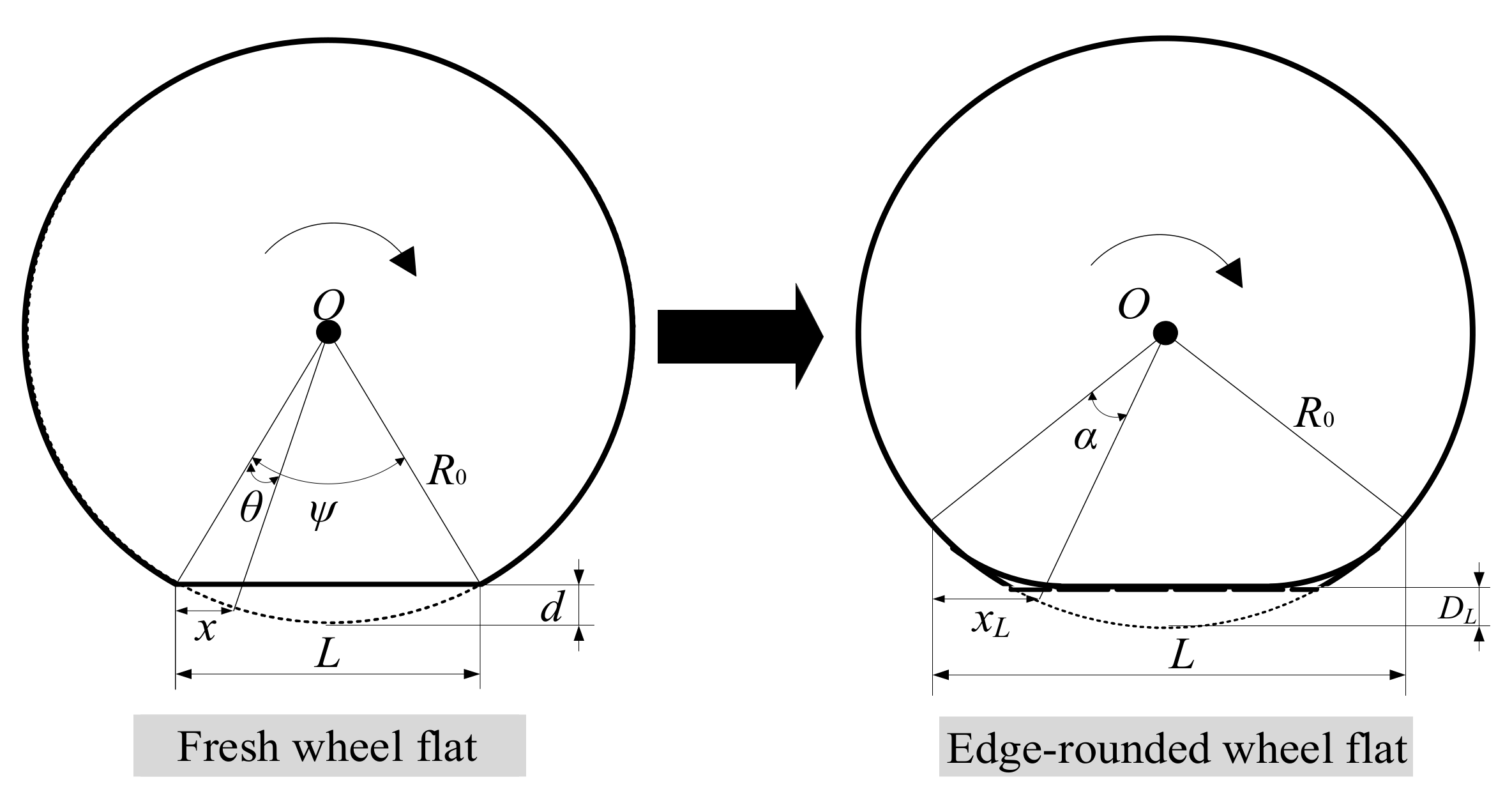
2.4. The Model of Wheel–Rail Interaction

As a common fault of the wheel, a wheel flat can generate a periodic impact at the wheel–rail contact area and significantly intensify the wheel–rail interaction, which is induced by emergency braking or skidding idling. During the operating of a locomotive, the straight edges of the fresh flat are rounded; therefore, it is more rational to analyze the effect of an edge−rounded wheel flat. The evolution process of the wheel flat is shown in Figure 4.
The time−varying displacement excitation induced by a wheel flat can be represented by the haversine wheel flat geometry [30], and the variation of the wheel radius with wheelset rotates in the defect area can be expressed as
Z f ( x L ) = 1 2 D L [ 1 cos ( 2 π x L L ) ]   0 x L L
where DL and L are the depth and length of the edge−rounded wheel flat, respectively. The relationship between the distance along the wheel circumference (xL) and the angle (αw) can be expressed as
x L = L 2 sin [ arcsin ( L / ( 2 R 0 ) ) α w ) ]   0 α w 2 arcsin ( L / ( 2 R 0 ) )
where R0 is the nominal rolling radius of a wheel.
In this study, the time−varying displacement excitation induced by a wheel flat is substituted for the wheel–rail elastic compressive deformation at the contact area. Therefore, based on the Hertz theory, the interactive force between the rail and the wheel with a flat can be calculated by
P t = 1 G Z w t Z rail x w , t Z 0 x w , t Z f ( x L , t ) 3 / 2
where G is the contact constant; Zw and Zrail are the vertical displacements of the wheelset and rail, respectively; and Z0 is the corresponding track irregularity [31,32].

2.5. Fatigue Life Prediction Method of Rolling Bearing

The service life of the motor bearing would be reduced significantly due to the effect of wheel–rail impact and gear engagement. It is essential to predict the fatigue life of the rolling bearing accurately for ensuring the reliability and safety of the locomotive. The L−P theory and ISO 281 are adopted in this study to analyze the fatigue damage and predict the service life of the motor bearing, respectively. It should be noted that, considering the effect of a lubricant regime, contamination, and bringing material fatigue stress limit, ISO 281 employs some modification factors to the L−P theory based on the tests.
Based on the Miner linear damage theory [33], the fatigue damage cumulative rule can be expressed as
D = i = 1 m ε i = i = 1 m l i L i
where εi is the fatigue damage ratio in one integration step; li and Li are the actual and theoretical inner race revolution in one integration step, respectively; and i and m are the serial number and the total number of the integration step, respectively.
The fatigue life in millions of inner race revolution of rolling bearings with 90% reliabilities can be calculated by using the L−P theory [13,14] or ISO method [20] as
L 10 = L i 9 8 + L o 9 8 8 9 = C i P i 4 × 9 8 + C o P o 4 × 9 8 8 9 by   using   L - P   theory L ISO = a 1 a ISO C ISO P ISO 10 / 3 by   using   ISO   method
where Li and Lo are fatigue life in millions of inner race revolution based on the contact loads of inner and outer races, respectively; Pi, Po, and PISO are the corresponding equivalent bearing loads, which can be extracted from the simulation results; a1 and aISO are the life correction factor for the reliability and the coupled influence of lubrication, contamination, and fatigue load limit of the material, respectively; Ci, Co, and CISO are the basic dynamic loads acting on the inner race, outer race, and the rolling bearing, which can, respectively, be calculated as
C i = 552 k λ i ( 1 γ ) 29 / 27 ( 1 + γ ) 1 / 4 2 R r 2 R m 2 / 9 2 R r 29 / 27 L e 7 / 9 N b 1 / 4
C o = 552 k λ o ( 1 + γ ) 29 / 27 ( 1 γ ) 1 / 4 2 R r 2 R m 2 / 9 2 R r 29 / 27 L e 7 / 9 N b 1 / 4
C ISO = b m f c k L e   cos α 7 / 9 N b 3 / 4 2 R r 29 / 27
where k is the number of columns of the rolling bearing; λi and λo are the reduction factors of inner and outer races for the stress concentration, respectively; γ = Rrcosα/Rm, is the structure parameter of the rolling bearing; α and Le are the roller−races contact angle and equivalent contact length, respectively; bm and fc are the key parameters determined by the bearing material and processing. The detailed descriptions for the above parameters are stated in [20,34].

3. Result Discussions

To analyze the dynamic behaviors of the locomotive subsystem and fatigue life of the motor bearing under the effect of wheel flat, an HX locomotive is adopted in this study, and dynamic excitations (e.g., wheel–rail interacted forces and time−varying mesh forces) are extracted from the simulation results. The parameters of the vehicle system, track structure, gear transmission, and the motor bearing can be referenced to [9,21]. A measured track random irregularity [10] is employed in this study to simulate the real service conditions of the locomotive. Given the large degrees of freedom of the coupled dynamic system and the efficiency and accuracy of simulation, the Zhai method [35] and Runge−Kutta method [36] are used to solve the dynamic equations of the LTM and rolling bearing with different integration steps (5 × 10⁻⁵ s, 1 × 10⁻⁵ s), respectively. This hybrid integration method can guarantee the accuracy and efficiency of the simulation.

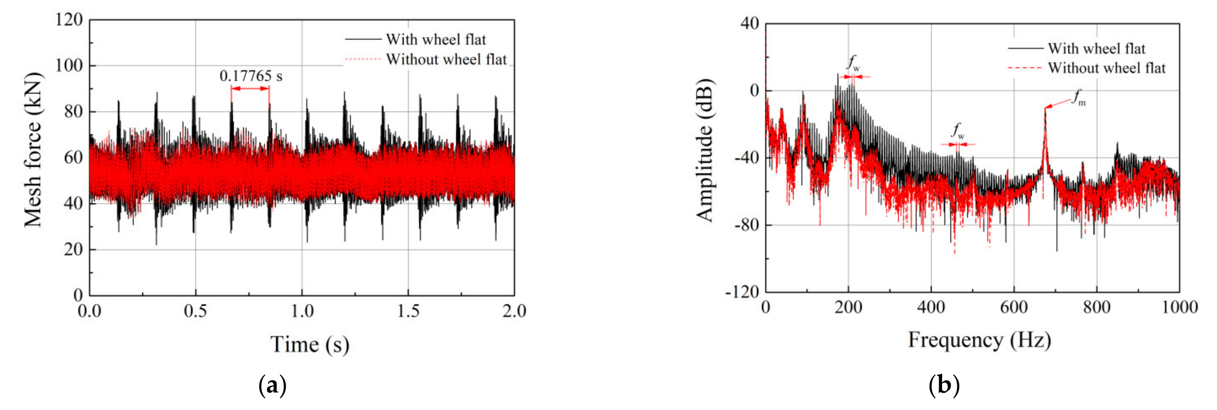
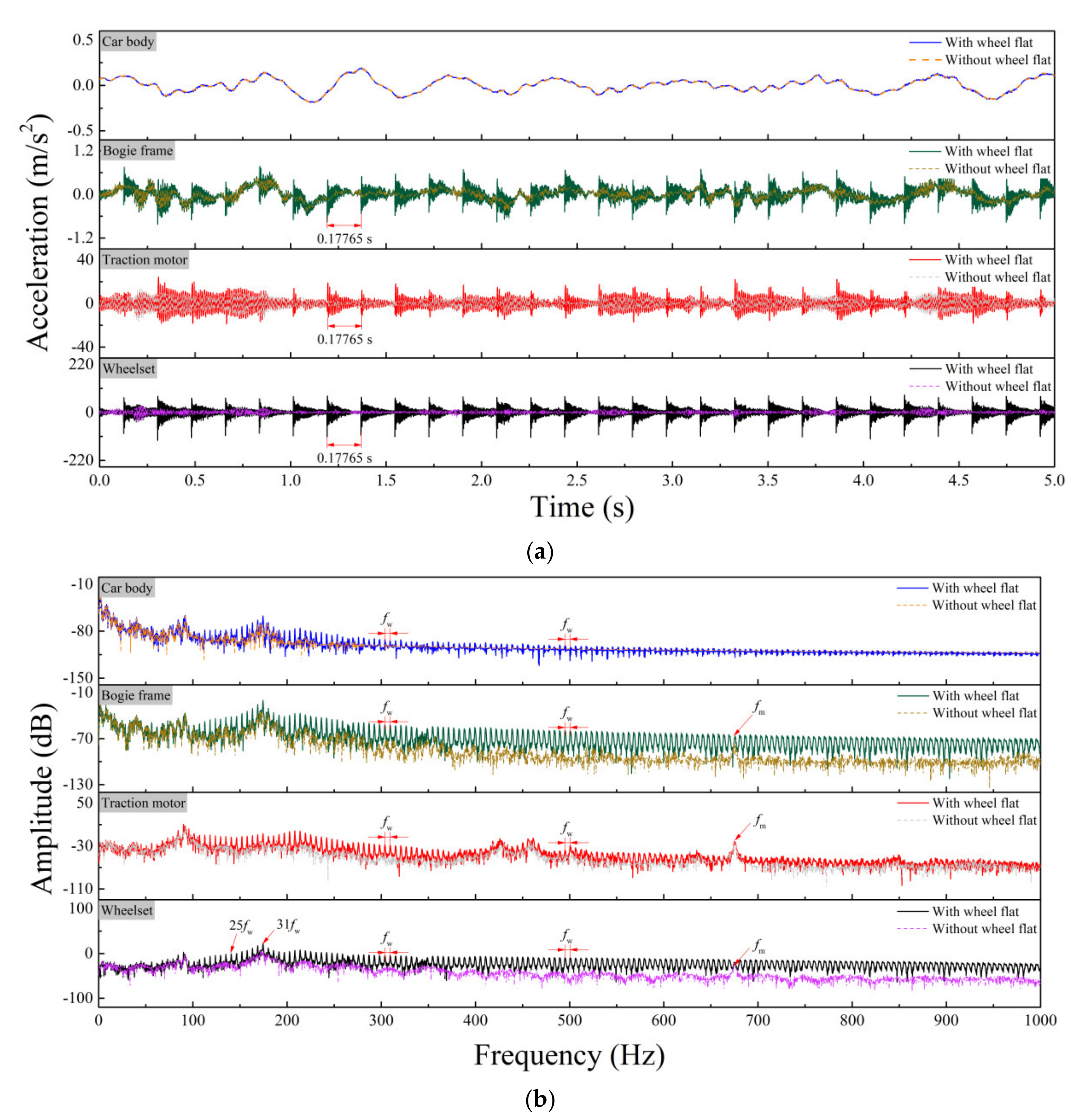
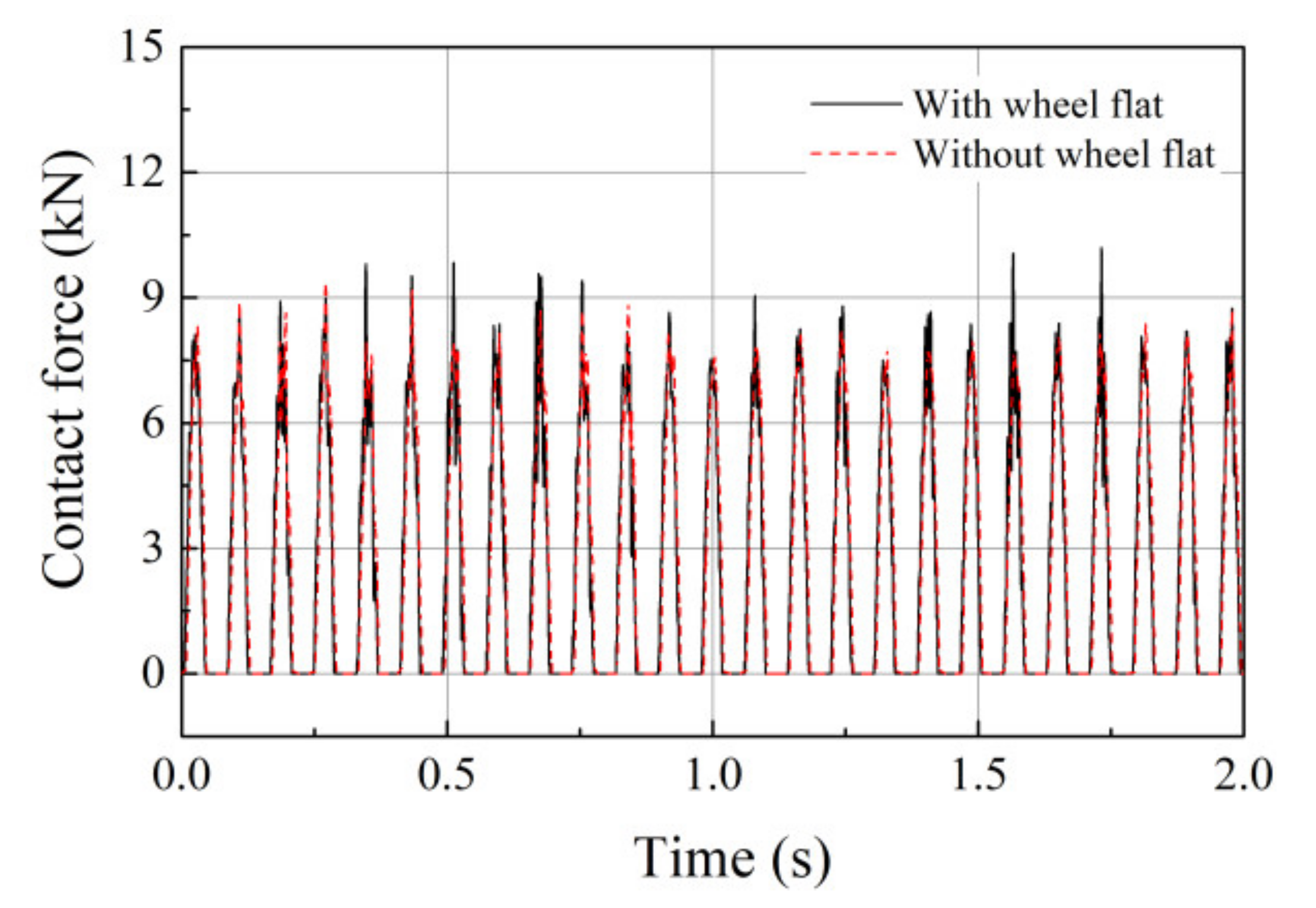
3.1. Dynamic Performance of System under the Effect of a Wheel Flat

The wheel–rail impact excited by the wheel flat affects the service conditions of the motor bearings via the gear mesh and structural vibrations transmission during the service of the locomotive. In this section, the relatively constant velocity of the locomotive is 80 km/h and a length of 30 mm in wheel flat is considered. The time histories and frequency spectrums regarding the wheel–rail contact forces, mesh forces, vertical vibrations of the components of the locomotive (e.g., the wheelset, traction motor, bogie frame, and car body), the contact forces and roller−races friction forces, and the fatigue damage ratios of the motor bearing are extracted from the simulation results and shown in Figure 5, Figure 6, Figure 7, Figure 8, Figure 9 and Figure 10. The corresponding rotation frequency of the wheelset (fw) and mesh frequency (fm) are 5.7 Hz and 680.5 Hz, respectively.
The wheel–rail interactions and mesh forces are the major excitations of the locomotive subsystems. As shown in Figure 5, an apparent impact generated at the wheel–rail interface will occur and decay owing to the damping effects of the vehicle and track structures during the wheel flat−rail contact process. According to Equations (14) and (15), the intensified planar vibrations of the pinion and gear will significantly affect the gear mesh forces. The root mean square (RMS) values of the wheel–rail contact forces and mesh forces increase approximately 6.45 kN and 0.26 kN, respectively. As shown in Figure 7, it is obvious that the service states of the components in a locomotive, especially the wheelset and traction motor, are significantly deteriorated by the additional periodical excitations of 5.7 Hz induced by the wheel flat. Due to the damping effect of the suspension system, there is little effect on the car body. It should be noted that, owing to the gear mesh and structure vibration transmission, the dynamic behaviors of the traction motor are sensitive to the wheel flat; specifically, the wheel flat is a potential threat to the dynamic characteristics of the motor bearings and their fatigue life.
Without loss of generality, the results extracted from the first roller are used to reveal the laws of motion variation representing the results for all rollers. The roller−race contact forces and the corresponding friction forces are shown in Figure 8. Compared with the results with a healthy wheel, the RMS value of the roller−race contact forces slightly increases approximately 0.01 kN. According to Equations (21) and (22), the fatigue damage ratios of the motor bearing calculated by L−P theory and ISO method are displayed in Figure 9a,b. It can be seen that the fatigue damage ratio is markedly elevated when the wheel flat−rail impact occurs, and the corresponding mean value (MV) increase approximately 0.08 × 10⁻¹³ and 0.15 × 10⁻¹³ for L−P theory and ISO method, respectively. Therefore, the wheel flat can pose a potential risk to the fatigue life of the motor bearings, and it can be predicted that the larger excitation excided by a worse wheel flat will seriously threaten the reliability and safety of bearings.

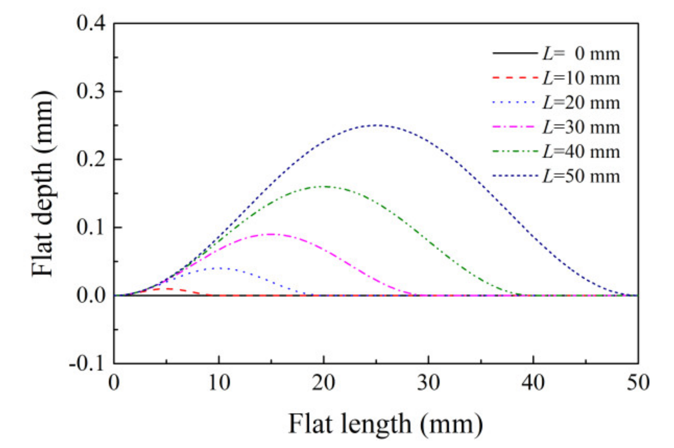
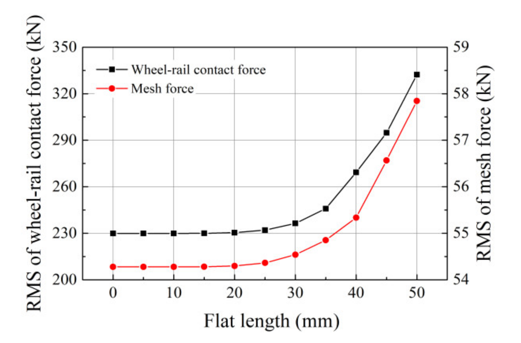
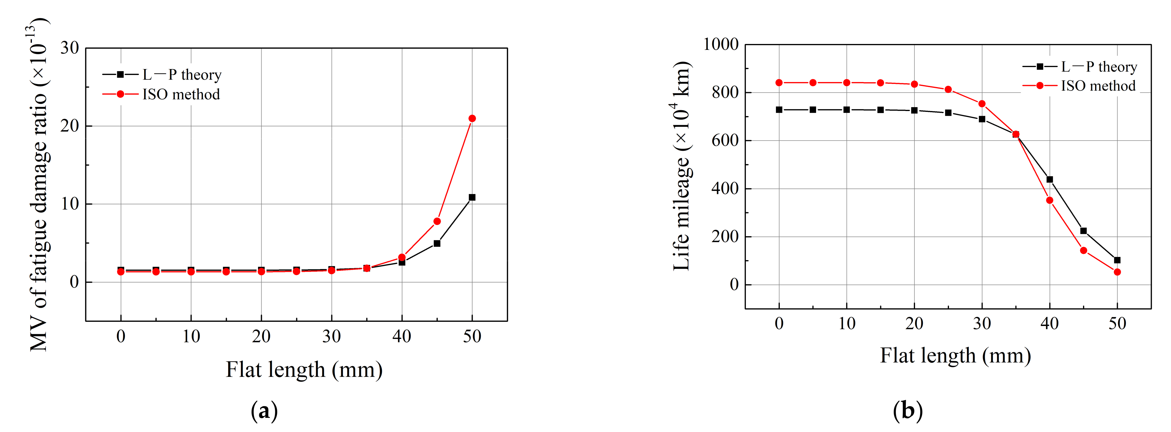
3.2. Effect of Flat Length

Based on the evaluation criteria for the tolerance limit of the wheel flat [37], it is acceptable that the length of the wheel flat is less than 50 mm for a wheelset with one flat during the interim train examination. Therefore, in order to study the influence of the length of the wheel flat on the fatigue life of the motor bearing, some time−varying displacement excitations with different lengths of the wheel flat (L = 0, 10, 20, 30, 40, 50 mm) are considered in simulations, and the corresponding profiles of the wheel flat are depicted in Figure 10. A growth could be seen in the amplitude of the flat depth while the length of the flat increases. As shown in Figure 11, the worse wheel flat can excite more intensified interactions between the wheel and rail in turn increase the mesh forces. This impact phenomenon will be more obvious when the flat length is larger than 25 mm. For the motor bearing, the MV of the fatigue damage ratio and the corresponding life mileage of the locomotive are, respectively displayed in Figure 12a,b. The life mileage can be calculated by
L m = v T i = 1 m ε i
where v is the relatively constant velocity of the locomotive; and T is the simulation time.
The results indicate that the service conditions and fatigue resistance of the motor bearings deteriorate gradually as the rise of the flat length. When the flat length is larger than 30 mm, the motor bearing will break down at an ever−increasing rate. This critical value is acceptable for the interim train examination based on the corresponding locomotive maintenance regulations. In addition, if a wheelset with a flat of 50 mm, the life mileage of motor bearing could be one−eighth of what the theory predicts. Therefore, the wheel flat has the potential to cause grave accidents and should be diagnosed and eliminated in the early stage of development.

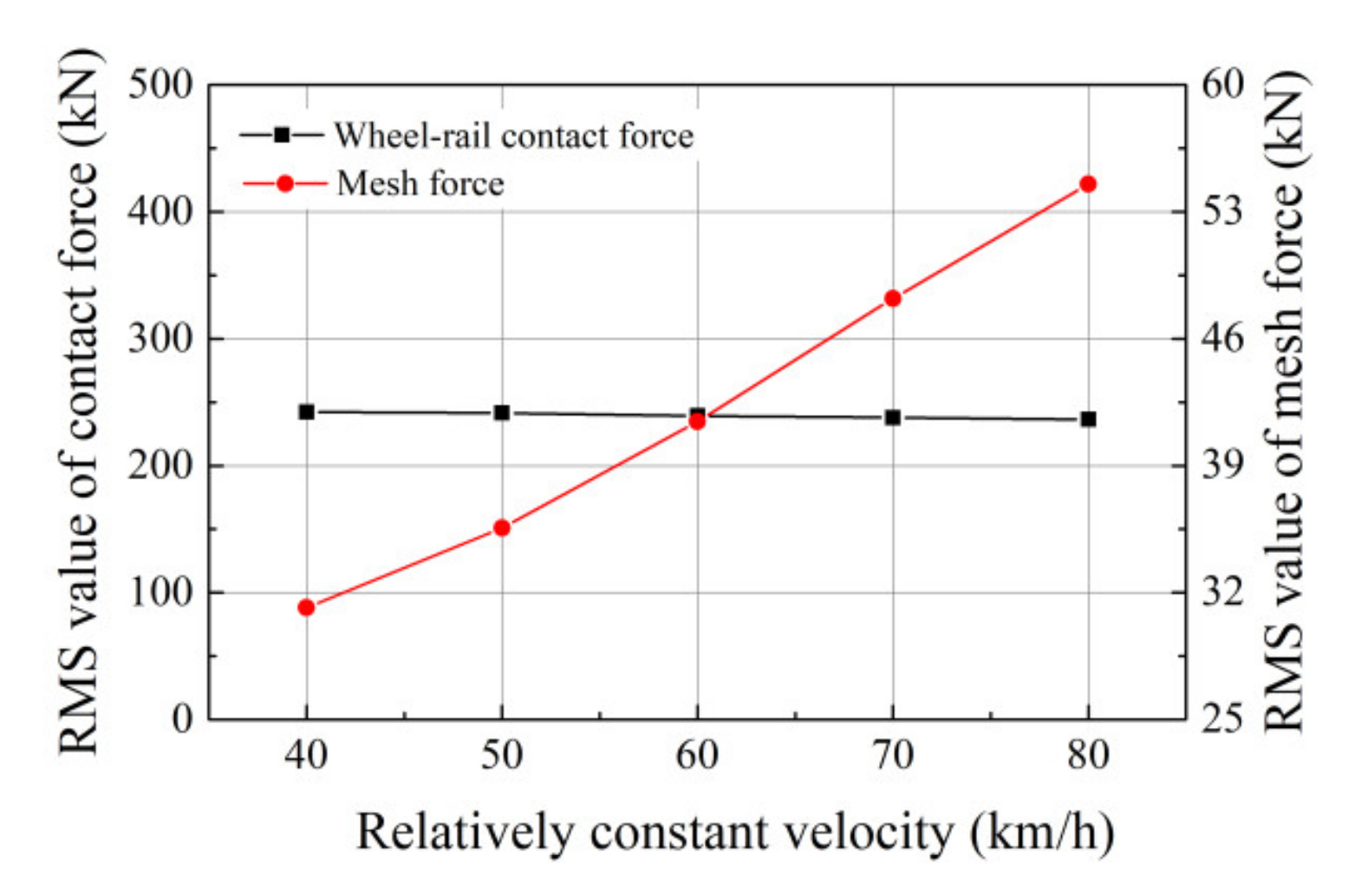
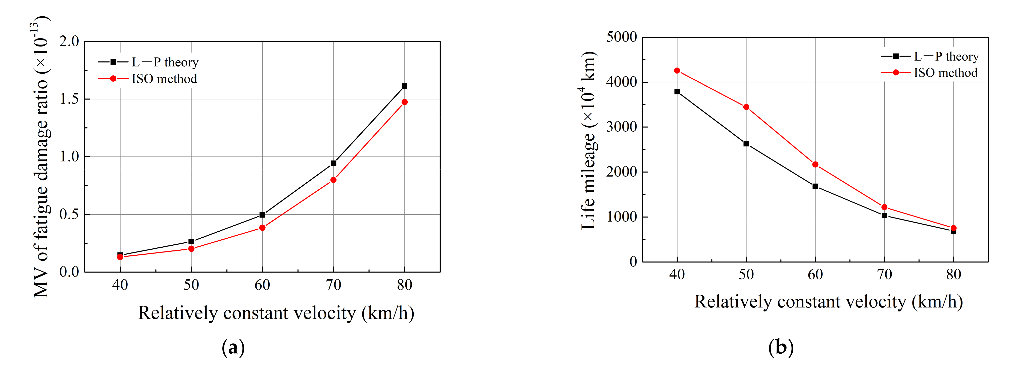
3.3. Effect of Relatively Constant Velocity

The relatively constant velocity is a major consideration in the operation process of the locomotive, which directly affects the interaction frequency between the wheel flat and rail. In this section, a wheel flat with a length of 30 mm is adopted in simulations under the different traction torques to remains the relatively constant velocity of the locomotive constant at 40, 50, 60, 70, and 80 km/h, respectively. As demonstrated in Figure 13, the RMS value of the wheel–rail contact force remains stable, but the wheel–rail impact frequency is significantly improved as a result of the increase in the rotational velocity of the wheelset. In addition, mesh force increases gradually under the larger traction torque and more high−frequency impact could be observed between the wheel flat and rail. The variations in MV of the fatigue damage ratio and life mileage of the locomotive are displayed in Figure 14. The results denote that the service life of the motor bearing decrease with increased machine velocity owing to the high−frequency wheel flat−rail impact and larger mesh forces. Under the growing traction torques, the negative effect of the wheel flat is aggrandizement as the speed increase. Thus, with the improvement of train speed and trainload, the early diagnosis for the wheel flat can efficiently improve the service life of the locomotive.

4. Conclusions

In this study, a fatigue life prediction method of the traction motor bearing in the environmental vibration of a locomotive is proposed so as to investigate the effect of the wheel flat on the service life of the motor bearings. The service life of the motor bearings is sensitive to the wheel–rail impact induced by the wheel flat via the structure vibration transmission and gear mesh. The simulation results indicate that the impulsive responses induced by the wheel flat can be observed in the time histories of the motions and forces. The wheel flat can significantly intensify the interactions between the roller and rail and increases the mesh forces of the gear pair. The fatigue damage ratio will be greater if an impact phenomenon occurs at the wheel–rail contact area under the effect of the wheel flat. Additionally, a large flat length will increase the time−varying displacement excitation induced by the wheel flat, which can pose a serious threat to the fatigue life of the motor bearing when the flat length is larger than 30 mm. With the increased relatively constant velocity of the locomotive, the higher wheel–rail impact frequency and larger gear mesh forces will decrease the fatigue life of the motor bearing. Therefore, based on the defect frequency of the wheel flat, namely the rotational frequency of the wheelset, it is essential to diagnose and eliminate the wheel flat in the early stage of development during routine maintenance to guarantee the service life of the motor bearings. Additionally, the corresponding maintenance standard could be considered to be improved for the safe and reliable operation of motor bearings. This study can provide a reference for amendments of the tolerance limit of the wheel flat from the perspective of the fatigue life of motor bearings.
It should be pointed out that there exist considerable differences between the dynamic responses of the driving and non−driving end motor bearings due to the different lateral distances between support bearings and pinion. Compared with the planar dynamics model adopted in this study, a spatial LTM can provide more reasonable external loads acting on the driving and non−driving end bearings, and more accurate fatigue lives of motor bearings can be predicated. In addition, two mature prediction methods, namely, L−P theory and ISO 281, are used in this study, and other alternative methods can be also suggested to be investigated. Additionally, the fatigue lives of axle box bearings of the locomotive or wagon can also be investigated by using this method in our further researches.

Author Contributions

Conceptualization, B.G. and Z.L.; methodology, B.Z. and Y.L.; formal analysis, B.G., Z.L. and Y.L.; investigation, B.Z.; resources, Z.C.; data curation, B.Z.; writing—original draft preparation, Y.L.; writing—review and editing, B.G., Z.L. and Y.L.; visualization, B.Z.; supervision, Z.C.; project administration, Z.C.; funding acquisition, Z.C. All authors have read and agreed to the published version of the manuscript.

Funding

This research was funded by the National Natural Science Foundation of China, grant numbers 52022083, 51775453 and Opening Research Funds for the State Key Laboratory of Heavy Duty AC Drive Electric Locomotive Systems Integration, grant number 172195100700.

Institutional Review Board Statement

Not applicable.

Informed Consent Statement

Not applicable.

Data Availability Statement

Not applicable.

Acknowledgments

This work was supported by the National Natural Science Foundation of China [grant numbers 52022083, 51775453] and Opening Research Funds for the State Key Laboratory of Heavy Duty AC Drive Electric Locomotive Systems Integration [grant number 172195100700].

Conflicts of Interest

The authors declare no conflict of interest.

Nomenclature

b0Manufacture and assembly errors of gear transmission, m
CcContact damping between the roller and cage, N·s/m
CmMesh damping, N·s/m
CiBasic dynamic load acting on inner race, N
CoBasic dynamic load acting on outer race, N
CISOBasic dynamic load acting on rolling bearing, N
DLDepth of the wheel flat, m
eRadial clearance of rolling bearing, m
eiClearance of gear transmission, m
FcRoller−cage friction force, N
FiRoller−inner race friction force, N
FixResultant force of the rolling bearing acting on inner race in longitudinal direction, N
FizResultant force of the rolling bearing acting on inner race in vertical direction, N
FoFriction force between the roller and outer race, N
FoxResultant force of the rolling bearing acting on outer race in longitudinal direction, N
FozResultant force of the rolling bearing acting on outer race in vertical direction, N
FmMesh force, N
gGravitational constant, m/s2
IrMoment of inertia of roller, kg·m2
jSerial number of roller
KcRoller−cage contact stiffness, N/m
KeEquivalent contact stiffness between races via the roller, N/m
KmTime−varying mesh stiffness, N/m
kNumber of columns of the rolling bearing
LLength of the edge-rounded wheel flat, m
LeEquivalent contact length between the roller and race, m
liActual inner race revolution in one integration step, r
LiTheoretical inner race revolution in one integration step, r
LiFatigue life based on contact loads of inner race, ×106 r
LoFatigue life based on contact loads of outer race, ×106 r
mrMass of the roller, kg
nLoad−deformation coefficient
NbNumber of rollers
NcRoller−cage contact force, N
NiRoller−inner race contact force, N
NoRoller−outer race contact force, N
PiEquivalent bearing load acting on inner race, N
PoEquivalent bearing load acting on outer race, N
PISOEquivalent bearing load acting on rolling bearing, N
RrRadius of roller, m
RmPitch radius, m
RpBase circle radius of pinion, m
RgBase circle radius of gear, m
XBearing races relative displacement in longitudinal direction, m
XpDisplacements of pinion in the longitudinal direction, m
XgDisplacements of gear in the longitudinal direction, m
xLDistance along the wheel circumference, m
ZBearing races relative displacement in vertical directions, m
ZfVariation of the wheel radius, m
ZpDisplacements of pinion in the vertical direction, m
ZgDisplacements of gear in the vertical direction, m
ZwVertical displacements of wheelset, m
ZrailVertical displacements of rail, m
Z0Track irregularity, m
θrRotational motion of roller, rad
σrCircumferential motions of roller, rad
σcCircumferential motions of cage, rad
μcRoller−cage friction coefficient
μTime−varying lubricant friction coefficient
ΔViRelative slip velocities between the roller and inner race, m/s
ΔVoRelative slip velocities between the roller and outer race, m/s
χjLoad zone parameter
ωiRotational velocities of the inner ring, rad/s
ωoRotational velocities of the outer ring, rad/s
δDynamic transmission error, m
αContact angle between the roller and race, rad
αmPressure angle of gear pair, rad
αwAngular along the wheel circumference, rad
εiFatigue damage ratio in one integration step
λiReduction factor of inner race for the stress concentration
λoReduction factor of outer race for the stress concentration
γStructure parameter of the rolling bearing

References

  1. Alam Uzzal, R.U.; Ahmed, W.; Rakheja, S. Dynamic analysis of railway vehicle-track interactions due to wheel flat with a pitch-plane vehicle model. J. Mech. Eng. 2008, 39, 86–94. [Google Scholar] [CrossRef] [Green Version]
  2. Dong, R.G.; Sankar, S.; Dukkipati, R.V. A Finite Element Model of Railway Track and its Application to the Wheel Flat Problem. Proc. Inst. Mech. Eng. Part F J. Rail Rapid Transit 1994, 208, 61–72. [Google Scholar] [CrossRef]
  3. Zhu, J.; Ahmed, A.; Rakheja, S. An adaptive contact model for simulation of wheel-rail impact load due to a wheel flat. In Proceedings of the 13th National Conference on Mechanisms and Machines, IISc, Bangalore, India, 12–13 December 2007; pp. 157–164. [Google Scholar]
  4. Steenbergen, M.J.M.M. The role of the contact geometry in wheel–rail impact due to wheel flats. Veh. Syst. Dyn. 2007, 45, 1097–1116. [Google Scholar] [CrossRef]
  5. Bian, J.; Gu, Y.; Murray, M.H. A dynamic wheel–rail impact analysis of railway track under wheel flat by finite element analysis. Veh. Syst. Dyn. 2013, 51, 784–797. [Google Scholar] [CrossRef] [Green Version]
  6. Zhou, Z.; Chen, Z.; Spiryagin, M.; Arango, E.B.; Wolfs, P.; Cole, C.; Zhai, W. Dynamic response feature of electromechanical coupled drive subsystem in a locomotive excited by wheel flat. Eng. Fail. Anal. 2021, 122, 105248. [Google Scholar] [CrossRef]
  7. Zhai, W.; Sun, X. A Detailed Model for Investigating Vertical Interaction between Railway Vehicle and Track. Veh. Syst. Dyn. 1994, 23, 603–615. [Google Scholar] [CrossRef]
  8. Chen, Z.; Zhai, W.; Wang, K. Vibration feature evolution of locomotive with tooth root crack propagation of gear transmission system. Mech. Syst. Signal Process. 2019, 115, 29–44. [Google Scholar] [CrossRef]
  9. Liu, Y.; Chen, Z.; Zhai, W.; Wang, K. Dynamic investigation of traction motor bearing in a locomotive under excitation from track random geometry irregularity. Int. J. Rail Transp. 2021, 1–23. [Google Scholar] [CrossRef]
  10. Liu, Y.; Chen, Z.; Wang, K.; Zhai, W. Dynamic modelling of traction motor bearings in locomotive-track spatially coupled dynamics system. Veh. Syst. Dyn. 2021, 1–30. [Google Scholar] [CrossRef]
  11. Liu, Y.; Chen, Z.; Li, W.; Wang, K. Dynamic analysis of traction motor in a locomotive considering surface waviness on races of a motor bearing. Railw. Eng. Sci. 2021, 1–15. [Google Scholar] [CrossRef]
  12. Wang, T.; Wang, Z.; Song, D.; Zhang, W.; Li, J.; Chen, D. Effect of track irregularities of high-speed railways on the thermal characteristics of the traction motor bearing. Proc. Inst. Mech. Eng. Part F J. Rail Rapid Transit 2020, 235, 22–34. [Google Scholar] [CrossRef]
  13. Lundberg, G.; Palmgren, A. Dynamic capacity of rolling bearings. J. Appl. Mech. 1949, 16, 165–172. [Google Scholar] [CrossRef]
  14. Palmgren, A. Ball and Roller Bearing Engineering, 3rd ed.; SKF Industries Inc.: Burbank, Philadelphia, 1959. [Google Scholar]
  15. Ioannides, E.; Harris, T.A. A New Fatigue Life Model for Rolling Bearings. J. Tribol. 1985, 107, 367–377. [Google Scholar] [CrossRef]
  16. Zhang, J.; Fang, B.; Hong, J.; Zhu, Y. Effect of preload on ball-raceway contact state and fatigue life of angular contact ball bearing. Tribol. Int. 2017, 114, 365–372. [Google Scholar] [CrossRef]
  17. Londhe, N.D.; Arakere, N.K.; Subhash, G. Extended Hertz Theory of Contact Mechanics for Case-Hardened Steels with Implications for Bearing Fatigue Life. J. Tribol. 2018, 140, 021401. [Google Scholar] [CrossRef]
  18. Gupta, P.K.; Zaretsky, E.V. New Stress-Based Fatigue Life Models for Ball and Roller Bearings. Tribol. Trans. 2018, 61, 304–324. [Google Scholar] [CrossRef]
  19. Jouini, N.; Revel, P.; Thoquenne, G. Influence of surface integrity on fatigue life of bearing rings finished by precision hard turning and grinding. J. Manuf. Process. 2020, 57, 444–451. [Google Scholar] [CrossRef]
  20. ISO. ISO 281 Method of Calculating Dynamic Load Rating and Rating Life of Rolling Bearings; International Organization for Standardization: Geneva, Switzerland, 2007. [Google Scholar]
  21. Chen, Z.; Zhai, W.; Wang, K. A locomotive–track coupled vertical dynamics model with gear transmissions. Veh. Syst. Dyn. 2016, 55, 244–267. [Google Scholar] [CrossRef]
  22. Chen, Z.; Zhai, W.; Wang, K. Dynamic investigation of a locomotive with effect of gear transmissions under tractive conditions. J. Sound Vib. 2017, 408, 220–233. [Google Scholar] [CrossRef]
  23. Weinzapfel, N.; Sadeghi, F. A Discrete Element Approach for Modeling Cage Flexibility in Ball Bearing Dynamics Simulations. J. Tribol. 2009, 131, 021102. [Google Scholar] [CrossRef]
  24. Liu, Y.; Chen, Z.; Tang, L.; Zhai, W. Skidding dynamic performance of rolling bearing with cage flexibility under accelerating conditions. Mech. Syst. Signal Process. 2021, 150, 107257. [Google Scholar] [CrossRef]
  25. Liu, J.; Xu, Y.; Pan, G. A combined acoustic and dynamic model of a defective ball bearing. J. Sound Vib. 2021, 501, 116029. [Google Scholar] [CrossRef]
  26. Liu, J.; Tang, C.; Wu, H.; Xu, Z.; Wang, L. An analytical calculation method of the load distribution and stiffness of an angular contact ball bearing. Mech. Mach. Theory 2019, 142, 103597. [Google Scholar] [CrossRef]
  27. Zhang, T.; Chen, Z.; Zhai, W.; Wang, K. Establishment and validation of a locomotive–track coupled spatial dynamics model considering dynamic effect of gear transmissions. Mech. Syst. Signal Process. 2019, 119, 328–345. [Google Scholar] [CrossRef]
  28. Chen, Z.; Zhou, Z.; Zhai, W.; Wang, K. Improved analytical calculation model of spur gear mesh excitations with tooth profile deviations. Mech. Mach. Theory 2020, 149, 103838. [Google Scholar] [CrossRef]
  29. Chen, Z.; Ning, J.; Wang, K.; Zhai, W. An improved dynamic model of spur gear transmission considering coupling effect between gear neighboring teeth. Nonlinear Dyn. 2021. [Google Scholar] [CrossRef]
  30. Bernal, E.; Spiryagin, M.; Cole, C. Wheel flat detectability for Y25 railway freight wagon using vehicle component acceleration signals. Veh. Syst. Dyn. 2019, 58, 1893–1913. [Google Scholar] [CrossRef]
  31. Xu, L.; Zhai, W. Train–track coupled dynamics analysis: System spatial variation on geometry, physics and mechanics. Railw. Eng. Sci. 2020, 28, 36–53. [Google Scholar] [CrossRef] [Green Version]
  32. Ge, X.; Ling, L.; Yuan, X.; Wang, K. Effect of distributed support of rail pad on vertical vehicle-track interactions. Constr. Build. Mater. 2020, 262, 120607. [Google Scholar] [CrossRef]
  33. Miner, M. Cumulative Damage in Fatigue. J. Appl. Mech. 1945, 3, 159–164. [Google Scholar] [CrossRef]
  34. Liu, D.; Li, Q.; Hu, W.; Pan, W. Fatigue life prediction of the axle box bearings for high-speed trains. DYNA 2017, 92, 538–544. [Google Scholar] [CrossRef] [Green Version]
  35. Zhai, W. Two simple fast integration methods for large-scale dynamic problems in engineering. Int. J. Numer. Methods Eng. 1996, 39, 4199–4214. [Google Scholar] [CrossRef]
  36. Dormand, J.R.; Prince, P.J. A family of embedded Runge-Kutta formulae. J. Comput. Appl. Math. 1980, 6, 19–26. [Google Scholar] [CrossRef] [Green Version]
  37. Ministry of Railways of the People’s Republic of China. Railway Passenger Car Service and Maintenance Regulations; China Railway Publishing House: Beijing, China, 2006. [Google Scholar]
Figure 1. Schematic of LTM.
Energies 14 05810 g001
Figure 2. Schematic of the rolling bearing.
Energies 14 05810 g002
Figure 3. Schematic diagram of gear mesh.
Energies 14 05810 g003
Figure 4. Geometric model of wheel flat.
Energies 14 05810 g004
Figure 5. Wheel−rail contact forces: (a) time histories and (b) frequency spectrum.
Energies 14 05810 g005
Figure 6. Time−varying mesh force: (a) time histories and (b) frequency spectrum.
Energies 14 05810 g006
Figure 7. Vibration responses of the locomotive subsystem: (a) time−histories and (b) frequency spectrum.
Energies 14 05810 g007
Figure 8. Contact forces between the roller and race.
Energies 14 05810 g008
Figure 9. Fatigue damage of the motor bearing calculated by using: (a) L−P theory and (b) ISO method.
Energies 14 05810 g009
Figure 10. Profile of wheel flats.
Energies 14 05810 g010
Figure 11. Variation of RMS of excitations versus the flat length.
Energies 14 05810 g011
Figure 12. Variations of life mileage of motor bearing versus the flat length: (a) RMS of instantaneous fatigue damage and (b) life mileage of the motor bearing.
Energies 14 05810 g012
Figure 13. Variations in RMS value of dynamic excitations versus the running speed.
Energies 14 05810 g013
Figure 14. Effect of the relatively constant velocity on fatigue damage of motor bearings: (a) variations in MV of fatigue damage ratio and (b) life mileage versus the relatively constant velocity.
Energies 14 05810 g014
Publisher’s Note: MDPI stays neutral with regard to jurisdictional claims in published maps and institutional affiliations.

