
Multilevel Inverter: A Survey on Classical and Advanced Topologies, Control Schemes, Applications to Power System and Future Prospects

 ,
,  , ,
, ,  and
and 
Abstract
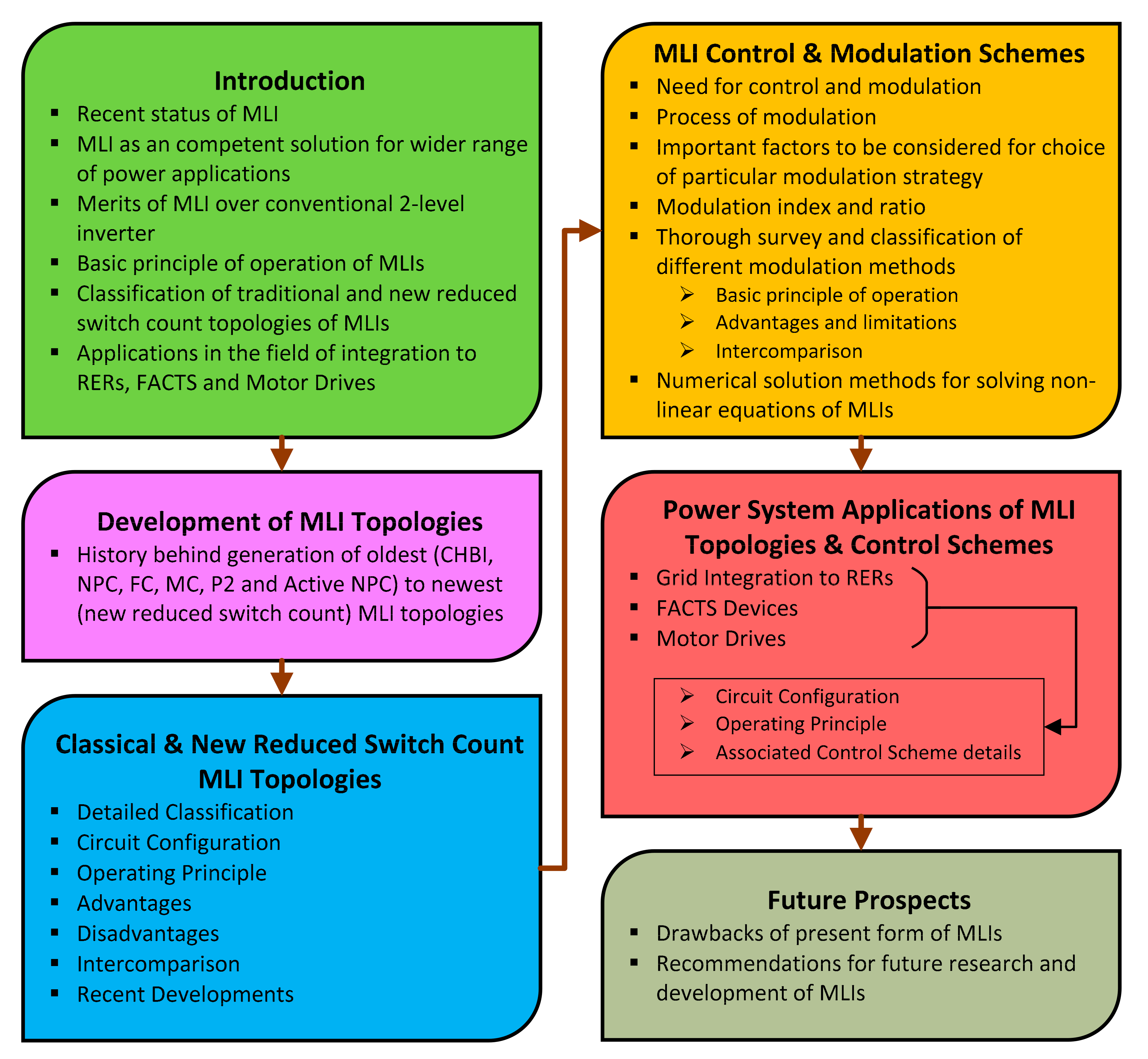
1. Introduction
- (1)
- More than 260 recent research articles have been critically reviewed, and a detailed literature summary about the evolution, classification of the MLI topologies, various modulation techniques, and application have been presented.
- (2)
- A detailed discussion concerning the various types of conventional MLI techniques has been carried out.
- (3)
- An extensive valuation of a wide range of possible new reduced switch count MLI topologies has been explored and presented in-depth.
- (4)
- A clear idea of the different modulation techniques required for MLI has been apprehended.
- (5)
- Further, this research paper also highlights a thorough knowledge of MLI novel applications in various fields of power system networks such as renewable energy interface, FACTS controller, and motor drives based on a comprehensive research survey.
- (6)
- Finally, this article also elaborately discusses the issues faced by the present MLI technology and suggests some more in-depth vital points to be adopted in the future for further better application in the electric power grid network.
- (7)
- This comprehensive article is alleged to serve as a good guidance for enhancing the understanding of readers, academics, and industrialists for researching in the area of MLI concerning the proper choice of topology for definite application, accurate selection of parameters, switching, control schemes, and application in other power system fields.
2. Development of MLI Topologies
3. Classical and New Reduced Switch Count MLI Topologies
3.1. Single DC Source
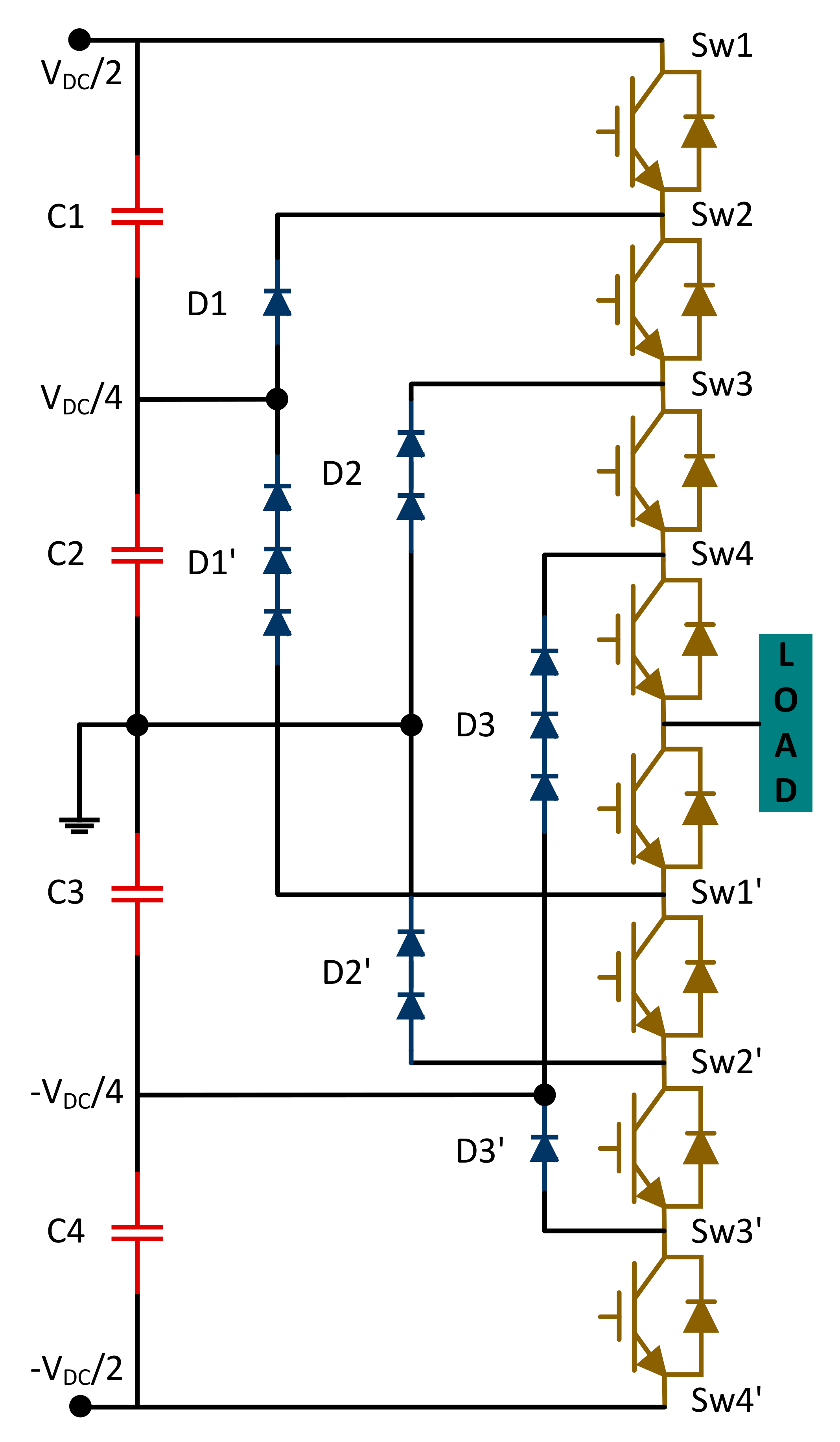
3.1.1. Neutral Point Clamped Multilevel Inverter (NPC-MLI)
3.1.2. Flying Capacitor Multilevel Inverter (FC-MLI)
3.1.3. Active Neutral Point Clamped Multilevel Inverter (ANPC-MLI)
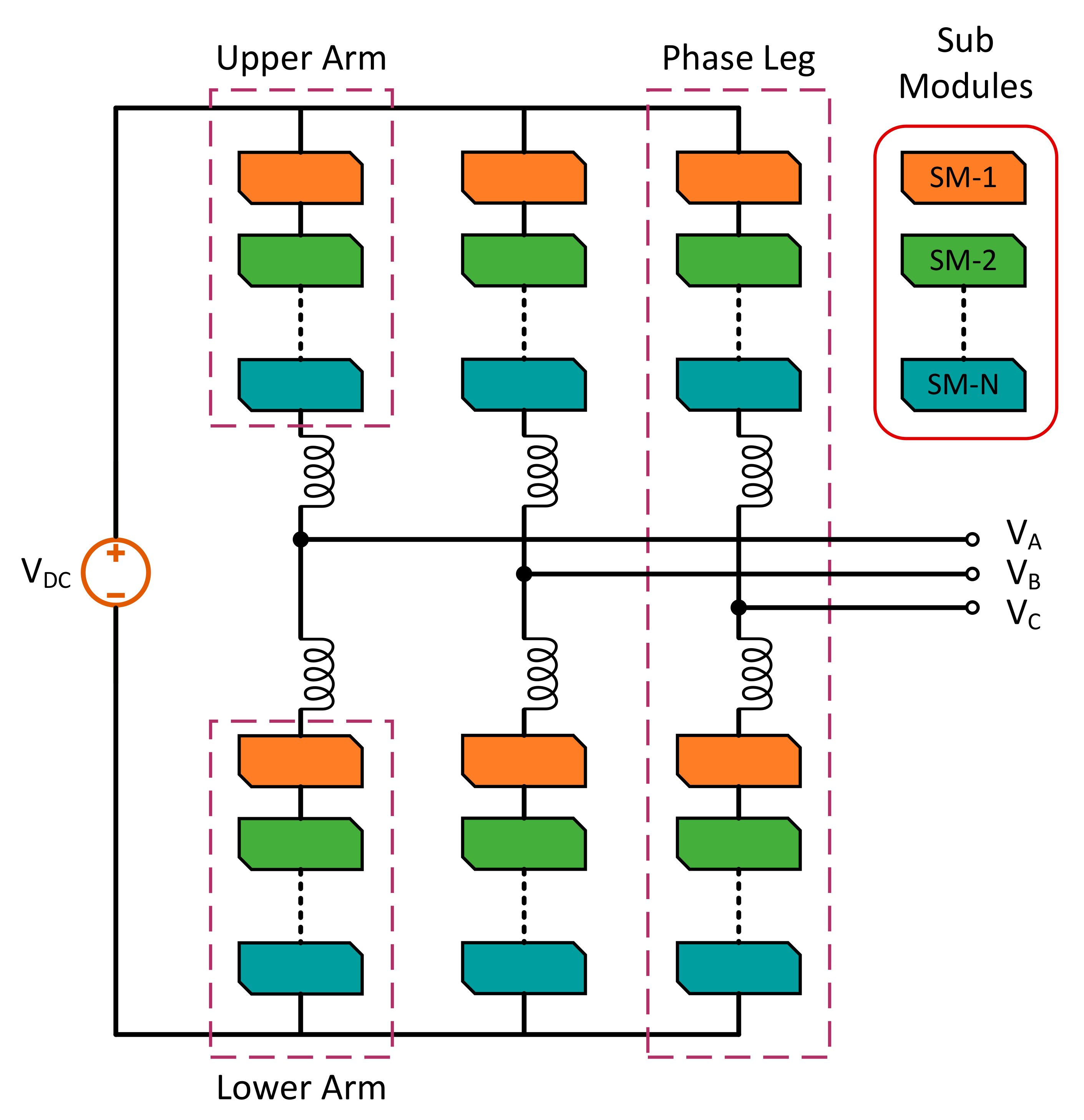
3.1.4. Modular Multilevel Converter (MMC)
3.2. Multiple DC Source
3.2.1. Basic Multiple DC Source Topology
Cascaded H-bridge Multilevel Inverter (CHB-MLI)
Hybridized Cascaded H-bridge Multilevel Inverter (HCHB-MLI)
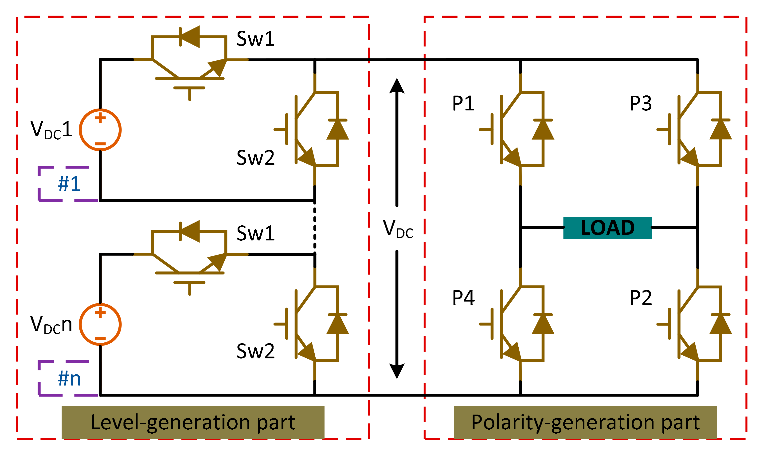
3.2.2. New Reduced Switch Count Topology
H-bridge Topologies
- (i)
- Asymmetric H-bridge Topology
- A.
- Cascaded H-bridge based Multiple Level DC Links Inverter
- B.
- Switched Series/Parallel Sources based Multilevel Inverter (SSPS-MLI)
- (ii)
- Symmetric H-bridge Topology
- A.
- T-type Multilevel Inverter
- B.
- Nilkar Multilevel Inverter (N-MLI)
- C.
- Crisscross Cascaded Multilevel Inverter (CCHB-MLI)
- D.
- Reversing Voltage Multilevel Inverter (RV-MLI)
- E.
- Series Connected Switched Sources Multilevel Inverter (SCSS-MLI)
- F.
- Multilevel Module Based Multilevel Inverter (MLM-MLI)
- G.
- Two Switch Enabled Level Generation Based Multilevel Inverter (2SELG-MLI)
- H.
- H-bridge and two-level Power Modules Based Multilevel Inverter (HBTPM-MLI)
Topologies without H-bridge
- (i)
- Asymmetric Topology without H-bridge
- (ii)
- Symmetric Topology without H-bridge
- A.
- Cross Connected Sources Based Multilevel Inverter (CCS-MLI)
- B.
- Packed U Cell Multilevel Inverter (PUC-MLI)
- C.
- Cascaded Bipolar Switched Cells Multilevel Inverter (CBSC-MLI)
- D.
- Mokhberdoran Multilevel Inverter (M-MLI)
- E.
- Babaei Multilevel Inverter (B-MLI)
4. MLI Control and Modulation Schemes
4.1. Fundamental Switching Frequency Pulse Width Modulation (FSF-PWM) Techniques
4.1.1. Sine Property
4.1.2. Selective Harmonic Elimination
4.1.3. Space Vector/Nearest Vector Control (SVC/NVC)
4.1.4. Staircase with a Fixed Time Step Control Scheme
4.2. High Switching Frequency Pulse Width Modulation (HSF-PWM) Techniques
4.2.1. Multi-Carrier Pulse Width Modulation (MC-PWM) Techniques
Carrier Disposition Pulse Width Modulation (CD-PWM) Techniques
- (i)
- Phase Disposition (PD) Method
- (ii)
- Phase Opposition Disposition (POD) Method
- (iii)
- Alternative Phase Opposition Disposition (APOD) Method
Phase-Shifted Pulse Width Modulation (PS-PWM) Technique
4.2.2. Hybrid Pulse Width Modulation (H-PWM) Technique
4.2.3. High and Low Carrier Cells and Alternative Phase Opposition Pulse Width Modulation (HLCCAPO-PWM) Technique
4.2.4. Space Vector Pulse Width Modulation (SV-PWM) Technique
5. Applications of MLI Topologies and Control Schemes
5.1. Grid Integration of RERs
5.2. FACTS Device
5.3. Motor Drives
6. Future Work
- (1)
- More research on contemporary topologies regarding the use of less power electronic interfaces, low cost, enhanced reliability, and efficiency should be developed.
- (2)
- Studies on designing a less complex inverter should be carried out.
- (3)
- Semiconductors with a large bandgap can be adopted for considerable increment in the switching frequency, thus facilitating the use of the smaller size of switching units.
- (4)
- The control and modulation schemes for MLI implementation should be further enhanced with more robust, modular, and fault-tolerance capability.
- (5)
- More in-depth work in the area of numerical methods for the solution of non-linear equations of MLI needs to be undertaken.
- (6)
- Extensive study is also required to balance the rise in temperature of the semiconductor devices used in the MLIs.
- (7)
- Integration of faster microprocessor units with the ability to work with high-level inverters and faster switching device applications should be adopted.
- (8)
- Building up more robust modulation schemes to assure uniformity in the rise of temperature of all devices and reduction in the complication of the controllers.
- (9)
- Design of reduced capacitor size by undertaking new voltage balancing methods needs to be used in MLI to enhance inverter’s power density.
- (10)
- Setting up of resonant converters basing on single DC source MLIs is recommended.
7. Conclusions
Author Contributions
Funding
Institutional Review Board Statement
Informed Consent Statement
Data Availability Statement
Conflicts of Interest
References
- Diaz, M.; Cardenas, R.; Espinoza, M.; Rojas, F.; Mora, A.; Clare, J.C.; Wheeler, P. Control of Wind Energy Conversion Systems Based on the Modular Multilevel Matrix Converter. IEEE Trans. Ind. Electron. 2017, 64, 8799–8810. [Google Scholar] [CrossRef]
- Wang, M.; Hu, Y.; Zhao, W.; Wang, Y.; Chen, G. Application of modular multilevel converter in medium voltage high power permanent magnet synchronous generator wind energy conversion systems. IET Renew. Power Gener. 2016, 10, 824–833. [Google Scholar] [CrossRef]
- Liu, Y.; Ge, B.; Abu-Rub, H.; Peng, F.Z. An Effective Control Method for Quasi-Z-Source Cascade Multilevel Inverter-Based Grid-Tie Single-Phase Photovoltaic Power System. IEEE Trans. Ind. Inform. 2013, 10, 399–407. [Google Scholar] [CrossRef]
- Ng, C.H.; Parker, M.A.; Ran, L.; Tavner, P.J.; Bumby, J.R.; Spooner, E. A multilevel modular converter for a large, light weight wind turbine generator. IEEE Trans. Power Electron. 2008, 23, 1062–1074. [Google Scholar] [CrossRef]
- Islam, R.; Guo, Y.; Zhu, J. A High-Frequency Link Multilevel Cascaded Medium-Voltage Converter for Direct Grid Integration of Renewable Energy Systems. IEEE Trans. Power Electron. 2013, 29, 4167–4182. [Google Scholar] [CrossRef]
- Debnath, S.; Saeedifard, M. A New Hybrid Modular Multilevel Converter for Grid Connection of Large Wind Turbines. IEEE Trans. Sustain. Energy 2013, 4, 1051–1064. [Google Scholar] [CrossRef]
- Chivite-Zabalza, J.; Izurza-Moreno, P.; Madariaga, D.; Calvo, G.; Rodríguez, M.A. Voltage Balancing control in 3-Level Neutral-Point Clamped Inverters Using Triangular Carrier PWM Modulation for FACTS Applications. IEEE Trans. Power Electron. 2013, 28, 4473–4484. [Google Scholar] [CrossRef]
- Ara, A.L.; Kazemi, A.; Niaki, S.A.N. Multiobjective Optimal Location of FACTS Shunt-Series Controllers for Power System Operation Planning. IEEE Trans. Power Deliv. 2011, 27, 481–490. [Google Scholar] [CrossRef]
- Hao, Q.; Ooi, B.-T. Tap for Classical HVDC Based on Multilevel Current-Source Inverters. IEEE Trans. Power Deliv. 2010, 25, 2626–2632. [Google Scholar] [CrossRef]
- Soto, D.; Green, T. A comparison of high-power converter topologies for the implementation of FACTS controllers. IEEE Trans. Ind. Electron. 2002, 49, 1072–1080. [Google Scholar] [CrossRef]
- Nami, A.; Liang, J.; Dijkhuizen, F.; Demetriades, G.D. Modular Multilevel Converters for HVDC Applications: Review on Converter Cells and Functionalities. IEEE Trans. Power Electron. 2014, 30, 18–36. [Google Scholar] [CrossRef]
- Ghat, M.B.; Shukla, A. A new H-bridge hybrid modular converter (HBHMC) for HVDC application: Operating modes, control, and voltage balancing. IEEE Trans. Power Electron. 2017, 33, 6537–6554. [Google Scholar] [CrossRef]
- Jung, J.-J.; Cui, S.; Lee, J.-H.; Sul, S.-K. A New Topology of Multilevel VSC Converter for a Hybrid HVDC Transmission System. IEEE Trans. Power Electron. 2016, 32, 4199–4209. [Google Scholar] [CrossRef]
- Feldman, R.; Tomasini, M.; Amankwah, E.; Clare, J.; Wheeler, P.; Trainer, D.R.; Whitehouse, R.S. A Hybrid Modular Multilevel Voltage Source Converter for HVDC Power Transmission. IEEE Trans. Ind. Appl. 2013, 49, 1577–1588. [Google Scholar] [CrossRef]
- Sajadi, R.; Iman-Eini, H.; Bakhshizadeh, M.K.; Neyshabouri, Y.; Farhangi, S. Selective Harmonic Elimination Technique with Control of Capacitive DC-Link Voltages in an Asymmetric Cascaded H-Bridge Inverter for STATCOM Application. IEEE Trans. Ind. Electron. 2018, 65, 8788–8796. [Google Scholar] [CrossRef]
- Babu, N.N.V.S.; Fernandes, B.G. Cascaded Two-Level Inverter-Based Multilevel STATCOM for High-Power Applications. IEEE Trans. Power Deliv. 2014, 29, 993–1001. [Google Scholar] [CrossRef]
- Haw, L.K.; Dahidah, M.S.A.; Almurib, H. SHE–PWM Cascaded Multilevel Inverter with Adjustable DC Voltage Levels Control for STATCOM Applications. IEEE Trans. Power Electron. 2014, 29, 6433–6444. [Google Scholar] [CrossRef]
- Liu, Y.; Luo, F. Trinary hybrid multilevel inverter used in STATCOM with unbalanced voltages. IEE Proc. Electr. Power Appl. 2005, 152, 1203–1222. [Google Scholar] [CrossRef]
- Liu, Y.; Yang, S.; Wang, X.; Gunasekaran, D.; Karki, U.; Peng, F.Z. Application of Transformer-Less UPFC for Interconnecting Two Synchronous AC Grids with Large Phase Difference. IEEE Trans. Power Electron. 2015, 31, 6092–6103. [Google Scholar] [CrossRef]
- Peng, F.Z.; Liu, Y.; Yang, S.; Zhang, S.; Gunasekaran, D.; Karki, U. Transformer-Less Unified Power-Flow Controller Using the Cascade Multilevel Inverter. IEEE Trans. Power Electron. 2016, 31, 5461–5472. [Google Scholar] [CrossRef]
- Wang, J.; Peng, F. Unified Power Flow Controller Using the Cascade Multilevel Inverter. IEEE Trans. Power Electron. 2004, 19, 1077–1084. [Google Scholar] [CrossRef]
- Rao, G.S.; Raju, S.S. Multilevel Inverter-Based Power Quality Improvement in Grid-Connected DVR System. In Micro-Electronics and Telecommunication Engineering; Springer: Singapore; pp. 361–366. [CrossRef]
- Dinesh, T. Performance Improvement of Constant Current Controller Based T-type DVR Multilevel Inverter for Solar PV Integrated with Grid. Turk. J. Comput. Math. Educ. (TURCOMAT) 2021, 12, 1465–1470. [Google Scholar]
- Hoon, Y.; Radzi, M.A.M.; Hassan, M.K.; Mailah, N.F. Operation of Three-Level Inverter-Based Shunt Active Power Filter under Nonideal Grid Voltage Conditions with Dual Fundamental Component Extraction. IEEE Trans. Power Electron. 2017, 33, 7558–7570. [Google Scholar] [CrossRef]
- Shu, Z.; Lin, H.; Ziwei, Z.; Yin, X.; Zhou, Q. Specific order harmonics compensation algorithm and digital implementation for multi-level active power filter. IET Power Electron. 2017, 10, 525–535. [Google Scholar] [CrossRef]
- Quraan, M.; Tricoli, P.; Arco, S.D.; Piegari, L. Efficiency Assessment of Modular Multilevel Converters for Battery Electric Vehicles. IEEE Trans. Power Electron. 2016, 32, 2041–2051. [Google Scholar] [CrossRef]
- Ali, M.; Mansoor, M.; Tang, H.; Rana, A. Analysis of a seven-level asymmetrical hybrid multilevel converter for traction systems. IET Power Electron. 2017, 10, 1878–1888. [Google Scholar] [CrossRef]
- Youssef, M.Z.; Woronowicz, K.; Aditya, K.; Azeez, N.A.; Williamson, S.S. Design and Development of an Efficient Multilevel DC/AC Traction Inverter for Railway Transportation Electrification. IEEE Trans. Power Electron. 2015, 31, 3036–3042. [Google Scholar] [CrossRef]
- Pereda, J.; Dixon, J. 23-Level Inverter for Electric Vehicles Using a Single Battery Pack and Series Active Filters. IEEE Trans. Veh. Technol. 2012, 61, 1043–1051. [Google Scholar] [CrossRef]
- Khoucha, F.; Lagoun, S.M.; Marouani, K.; Kheloui, A.; Benbouzid, M.E.H. Hybrid Cascaded H-Bridge Multilevel-Inverter Induction-Motor-Drive Direct Torque Control for Automotive Applications. IEEE Trans. Ind. Electron. 2009, 57, 892–899. [Google Scholar] [CrossRef]
- Du, Z.; Ozpineci, B.; Tolbert, L.; Chiasson, J.N. DC–AC Cascaded H-Bridge Multilevel Boost Inverter with No Inductors for Electric/Hybrid Electric Vehicle Applications. IEEE Trans. Ind. Appl. 2009, 45, 963–970. [Google Scholar] [CrossRef]
- Carpita, M.; Marchesoni, M.; Pellerin, M.; Moser, D. Multilevel Converter for Traction Applications: Small-Scale Prototype Tests Results. IEEE Trans. Ind. Electron. 2008, 55, 2203–2212. [Google Scholar] [CrossRef]
- Tolbert, L.; Peng, F.Z.; Cunnyngham, T.; Chiasson, J. Charge balance control schemes for cascade multilevel converter in hybrid electric vehicles. IEEE Trans. Ind. Electron. 2002, 49, 1058–1064. [Google Scholar] [CrossRef]
- Bucknall, R.W.G.; Ciaramella, K.M. On the Conceptual Design and Performance of a Matrix Converter for Marine Electric Propulsion. IEEE Trans. Power Electron. 2009, 25, 1497–1508. [Google Scholar] [CrossRef]
- Apsley, J.; Gonzalez-Villasenor, A.; Barnes, M.; Smith, A.; Williamson, S.; Schuddebeurs, J.D.; Norman, P.J.; Booth, C.; Burt, G.; McDonald, J.R. Propulsion Drive Models for Full Electric Marine Propulsion Systems. IEEE Trans. Ind. Appl. 2009, 45, 676–684. [Google Scholar] [CrossRef]
- Gritter, D.; Kalsi, S.; Henderson, N. Variable speed electric drive options for electric ships. In Proceedings of the IEEE Electric Ship Technologies Symposium, Philadelphia, PA, USA, 27 July 2005; pp. 347–354. [Google Scholar] [CrossRef]
- Corzine, K.A.; Lu, S. Comparison of hybrid propulsion drive schemes. In Proceedings of the IEEE Electric Ship Technologies Symposium, Philadelphia, PA, USA, 27 July 2005; pp. 355–362. [Google Scholar] [CrossRef]
- Shuai, L.; Corzine, K. Multilevel multi-phase propulsion drives. In Proceedings of the IEEE Electric Ship Technologies Symposium, Philadelphia, PA, USA, 27 July 2005; pp. 363–370. [Google Scholar] [CrossRef]
- Rodriguez, J.; Lai, J.; Peng, F.Z. Multilevel inverters: A survey of topologies, controls, and applications. IEEE Trans. Ind. Electron. 2002, 49, 724–738. [Google Scholar] [CrossRef]
- Rodriguez, J.; Pontt, J.; Alzarnora, G.; Becker, N.S.; Einenkel, O.; Weinstein, A.J. Novel 20-MW downhill conveyor system using three-level converters. IEEE Trans. Ind. Electron. 2002, 49, 1093–1100. [Google Scholar] [CrossRef]
- Kouro, S.; Rebolledo, J.; Rodríguez, J. Reduced switching-frequency-modulation algorithm for high-power multilevel inverters. IEEE Trans. Ind. Electron. 2007, 54, 2894–2901. [Google Scholar] [CrossRef]
- Sabate, J.; Garces, L.J.; Szczesny, P.M.; Li, Q.; Wirth, W.F. High-power high-fidelity switching amplifier driving gradient coils for MRI systems. In Proceedings of the 2004 IEEE 35th Annual Power Electronics Specialists Conference, Aachen, Germany, 20–25 June 2004; Volume 1, pp. 261–266. [Google Scholar] [CrossRef]
- Yue, Y.; Xu, Q.; Luo, A.; Guo, P.; He, Z.; Li, Y. Analysis and control of tundish induction heating power supply using modular multilevel converter. IET Gener. Transm. Distrib. 2018, 12, 3452–3460. [Google Scholar] [CrossRef]
- Siahbalaee, J.; Sanaie, N. Comparison of conventional and new cascaded multilevel inverter topologies based on novel indices. ISA Trans. 2021. [Google Scholar] [CrossRef] [PubMed]
- Islam, M.; Mekhilef, S.; Hasan, M. Single phase transformerless inverter topologies for grid-tied photovoltaic system: A review. Renew. Sustain. Energy Rev. 2015, 45, 69–86. [Google Scholar] [CrossRef]
- Chamarthi, P.K.; Al-Durra, A.; El-Fouly, T.H.M.; Al Jaafari, K.A. A Novel Three-Phase Transformerless Cascaded Multilevel Inverter Topology for Grid-Connected Solar PV Applications. IEEE Trans. Ind. Appl. 2021, 57, 2285–2297. [Google Scholar] [CrossRef]
- Kazmierkowski, M.P.; Franquelo, L.G.; Rodriguez, J.; Perez, M.A.; Leon, J.I. High-performance motor drives. IEEE Ind. Electron. Mag. 2011, 5, 6–26. [Google Scholar] [CrossRef]
- Kouro, S.; Malinowski, M.; Gopakumar, K.; Pou, J.; Franquelo, L.G.; Wu, B.; Rodriguez, J.; Perez, M.A.; Leon, J.I. Recent Advances and Industrial Applications of Multilevel Converters. IEEE Trans. Ind. Electron. 2010, 57, 2553–2580. [Google Scholar] [CrossRef]
- Khoucha, F.; Lagoun, M.S.; Kheloui, A.; Benbouzid, M.E.H. A Comparison of Symmetrical and Asymmetrical Three-Phase H-Bridge Multilevel Inverter for DTC Induction Motor Drives. IEEE Trans. Energy Convers. 2010, 26, 64–72. [Google Scholar] [CrossRef]
- Ali, A.I.M.; Sayed, M.A.; Takeshita, T. Isolated single-phase single-stage DC-AC cascaded transformer-based multilevel inverter for stand-alone and grid-tied applications. Int. J. Electr. Power Energy Syst. 2020, 125, 106534. [Google Scholar] [CrossRef]
- Agrawal, R.; Jain, S. Comparison of reduced part count multilevel inverters (RPC-MLIs) for integration to the grid. Int. J. Electr. Power Energy Syst. 2017, 84, 214–224. [Google Scholar] [CrossRef]
- Baker, R.H.; Bannister, L.H. Electric Power Converter. U.S. Patent 3,867,643, 18 February 1975. [Google Scholar]
- Mcmurray, W. Fast Response Stepped-Wave Switching Power Converter Circuit. U.S. Patent 3,581,212, 25 May 1971. [Google Scholar]
- Dickerson, J.A.; Ottaway, G.H. Transformerless Power Supply with Line to Load Isolation. U.S. Patent No. 3,596,369, 3 August 1971. [Google Scholar]
- Peng, F.Z.; Lai, J.-S.; McKeever, J.; VanCoevering, J. A multilevel voltage-source inverter with separate DC sources for static VAr generation. IEEE Trans. Ind. Appl. 1996, 32, 1130–1138. [Google Scholar] [CrossRef]
- Akira, N.; Takahashi, I.; Akagi, H. A new neutral-point-clamped PWM inverter. IEEE Trans. Ind. Appl. 1981, 5, 518–523. [Google Scholar]
- Baker, R.H. High-Voltage Converter Circuit. U.S. Patent 4,203,151, 13 May 1980. [Google Scholar]
- Baker, R.H. Bridge Converter Circuit. U.S. Patent 4,270,163, 26 May 1981. [Google Scholar]
- Rodriguez, J.; Bernet, S.; Steimer, P.K.; Lizama, I.E. A survey on neutral-point-clamped inverters. IEEE Trans. Ind. Electron. 2009, 57, 2219–2230. [Google Scholar] [CrossRef]
- Meynard, T.; Foch, H. Multi-level conversion: High voltage choppers and voltage-source inverters. In Proceedings of the PESC’92 Record. 23rd Annual IEEE Power Electronics Specialists Conference, Toledo, Spain, 29 June–3 July 1992; Volume 1, pp. 397–403. [Google Scholar] [CrossRef]
- Lavieville, J.; Carrere, P.; Meynard, T. Electronic Circuit for Converting Electrical Energy, and a Power Supply Installation Making Use Thereof. U.S. Patent 5,668,711, 16 September 1997. [Google Scholar]
- Marquardt, R. Stromrichterschaltungen mit Verteilten Energiespeichern. German Patent DE10103031A1, 24 January 2001. [Google Scholar]
- Rainer, M.; Lesnicar, A.; Hildinger, J. Modulares Stromrichterkonzept für Netzkupplungsanwendung bei Hohen Spannungen; ETG-Fachtagung: Bad Nauheim, Germany, 2002; p. 114. [Google Scholar]
- Peng, F.Z. A generalized multilevel inverter topology with self voltage balancing. IEEE Trans. Ind. Appl. 2001, 37, 611–618. [Google Scholar] [CrossRef]
- Barbosa, P.; Steimer, P.; Meysenc, L.; Winkelnkemper, M.; Steinke, J.; Celanovic, N. Active neutral-point-clamped multilevel converters. In Proceedings of the IEEE 36th Power Electronics Specialists Conference, Dresden, Germany, 16 June 2005; pp. 2296–2301. [Google Scholar]
- Omer, P.; Kumar, J.; Surjan, B.S. A Review on Reduced Switch Count Multilevel Inverter Topologies. IEEE Access 2020, 8, 22281–22302. [Google Scholar] [CrossRef]
- Siddique, M.D.; Iqbal, A.; Memon, M.A.; Mekhilef, S. A New Configurable Topology for Multilevel Inverter with Reduced Switching Components. IEEE Access 2020, 8, 188726–188741. [Google Scholar] [CrossRef]
- Bruckner, T.; Bernet, S.; Guldner, H. The Active NPC Converter and Its Loss-Balancing Control. IEEE Trans. Ind. Electron. 2005, 52, 855–868. [Google Scholar] [CrossRef]
- Gupta, K.K.; Jain, S. A Novel Multilevel Inverter Based on Switched DC Sources. IEEE Trans. Ind. Electron. 2013, 61, 3269–3278. [Google Scholar] [CrossRef]
- Babaei, E.; Laali, S.; Alilu, S. Cascaded Multilevel Inverter with Series Connection of Novel H-Bridge Basic Units. IEEE Trans. Ind. Electron. 2014, 61, 6664–6671. [Google Scholar] [CrossRef]
- Babaei, E. A Cascade Multilevel Converter Topology with Reduced Number of Switches. IEEE Trans. Power Electron. 2008, 23, 2657–2664. [Google Scholar] [CrossRef]
- Su, G. Multilevel DC-link inverter. IEEE Trans. Ind. Appl. 2005, 41, 848–854. [Google Scholar] [CrossRef]
- Mudadla, D.; Rao, G.R.; Sandeep, N. Novel asymmetrical multilevel inverter topology with reduced number of switches for photovoltaic applications. In Proceedings of the 2015 International Conference on Computation of Power, Energy,, Information and Communication (ICCPEIC), Melmaruvathur, India, 22–23 April 2015; pp. 123–128. [Google Scholar] [CrossRef]
- Gautam, S.P.; Kumar, L.; Gupta, S. A modified structure for symmetrical and asymmetrical configuration of multilevel inverter. In Proceedings of the IECON 2015-41st Annual Conference of the IEEE Industrial Electronics Society, Yokohama, Japan, 9–12 November 2015; pp. 1430–1435. [Google Scholar] [CrossRef]
- Kashif, M.F.; Rashid, A.K. A multilevel inverter topology with reduced number of switches. In Proceedings of the 2016 International Conference on Intelligent Systems Engineering (ICISE), Islamabad, Pakistan, 15–17 January 2016; pp. 268–271. [Google Scholar]
- Kang, S.H.; Lee, F.S. A new structure of H-bridge multilevel inverter. In Proceedings of the Annual Fall Conference of Power Electronics (KIPE Conference), Goyang, Korea, 31 October 2008; pp. 388–390. [Google Scholar]
- Choi, W.; Kang, F. H-bridge based multilevel inverter using PWM switching function. In Proceedings of the INTELEC 2009-31st International Telecommunications Energy Conference, Incheon, Korea, 18–22 October 2009; pp. 1–5. [Google Scholar]
- Najafi, E.; Yatim, A.H. Design and Implementation of a New Multilevel Inverter Topology. IEEE Trans. Ind. Electron. 2011, 59, 4148–4154. [Google Scholar] [CrossRef]
- Ebrahimi, J.; Babaei, E.; Gharehpetian, G.B. A New Multilevel Converter Topology with Reduced Number of Power Electronic Components. IEEE Trans. Ind. Electron. 2011, 59, 655–667. [Google Scholar] [CrossRef]
- Ceglia, G.; Guzman, V.; Sanchez, C.; Ibanez, F.; Walter, J.; Gimenez, M. A New Simplified Multilevel Inverter Topology for DC–AC Conversion. IEEE Trans. Power Electron. 2006, 21, 1311–1319. [Google Scholar] [CrossRef]
- Martins, G.; Pomilio, J.A.; Buso, S.; Spiazzi, G. Three-Phase Low-Frequency Commutation Inverter for Renewable Energy Systems. IEEE Trans. Ind. Electron. 2006, 53, 1522–1528. [Google Scholar] [CrossRef]
- Rahim, N.A.; Chaniago, K.; Selvaraj, J. Single-Phase Seven-Level Grid-Connected Inverter for Photovoltaic System. IEEE Trans. Ind. Electron. 2010, 58, 2435–2443. [Google Scholar] [CrossRef]
- Farhadi-Kangarlu, M.; Babaei, E. A Generalized Cascaded Multilevel Inverter Using Series Connection of Submultilevel Inverters. IEEE Trans. Power Electron. 2012, 28, 625–636. [Google Scholar] [CrossRef]
- Narimani, M.; Wu, B.; Zargari, N.R. A Novel Five-Level Voltage Source Inverter with Sinusoidal Pulse Width Modulator for Medium-Voltage Applications. IEEE Trans. Power Electron. 2015, 31, 1959–1967. [Google Scholar] [CrossRef]
- Le, Q.A.; Lee, D.-C. A Novel Six-Level Inverter Topology for Medium-Voltage Applications. IEEE Trans. Ind. Electron. 2016, 63, 7195–7203. [Google Scholar] [CrossRef]
- Kumari, M.; Siddique, M.D.; Sarwar, A.; Tariq, M.; Mekhilef, S.; Iqbal, A. Recent trends and review on switched-capacitor-based single-stage boost multilevel inverter. Int. Trans. Electr. Energy Syst. 2021, 31, e12730. [Google Scholar] [CrossRef]
- Kaarthik, R.S.; Kshirsagar, A.; Gopakumar, K. Generation of Higher Number of Voltage Levels by Stacking Inverters of Lower Multilevel Structures with Low Voltage Devices for Drives. IEEE Trans. Power Electron. 2017, 32, 52–59. [Google Scholar] [CrossRef]
- Panda, K.P.; Bana, P.R.; Panda, G. A Switched-Capacitor Self-Balanced High-Gain Multilevel Inverter Employing a Single DC Source. IEEE Trans. Circuits Syst. II Express Briefs 2020, 67, 3192–3196. [Google Scholar] [CrossRef]
- Yeganeh, M.S.O.; Davari, P.; Chub, A.; Mijatovic, N.; Dragicevic, T.; Blaabjerg, F. A Single-Phase Reduced Component Count Asymmetrical Multilevel Inverter Topology. IEEE J. Emerg. Sel. Top. Power Electron. 2021, 1. [Google Scholar] [CrossRef]
- Tolbert, L.; Peng, F.; Habetler, T. Multilevel inverters for electric vehicle applications. In Proceedings of the Power Electronics in Transportation (Cat. No.98TH8349), Dearborn, MI, USA, 22–23 October 1998; pp. 79–84. [Google Scholar] [CrossRef]
- Bendre, A.; Krstic, S.; Meer, J.; Venkataramanan, G. Comparative evaluation of modulation algorithms for neutral point clamped converters. In Proceedings of the Conference Record of the 2004 IEEE Industry Applications Conference, Seattle, WA, USA, 3–7 October 2004; Volume 2, pp. 798–805. [Google Scholar] [CrossRef]
- Joos, G.; Huang, X.; Ooi, B.-T. Direct-coupled multilevel cascaded series VAr compensators. IEEE Trans. Ind. Appl. 1998, 34, 1156–1163. [Google Scholar] [CrossRef]
- Çolak, I.; Kabalci, E. A review on inverter topologies and developments. In Proceedings of the Electrics, Electronics and Computer Engineering Symposium, Bursa, Turkey, 26–30 November; 2008. [Google Scholar]
- Purkait, P.; Sriramakavacham, R.S. A New Generalized Space Vector Modulation Algorithm for Neutral-point-clamped Multilevel Converters. PIERS Online 2006, 2, 330–335. [Google Scholar] [CrossRef][Green Version]
- Sadigh, A.K.; Hosseini, S.H.; Sabahi, M.; Gharehpetian, G.B. Double Flying Capacitor Multicell Converter Based on Modified Phase-Shifted Pulsewidth Modulation. IEEE Trans. Power Electron. 2009, 25, 1517–1526. [Google Scholar] [CrossRef]
- Bruckner, T.; Bemet, S. Loss balancing in three-level voltage source inverters applying active NPC switches. In Proceedings of the IEEE 32nd Annual Power Electronics Specialists Conference (IEEE Cat. No. 01CH37230), Vancouver, Canada, 17–21 June 2001; Volume 2, pp. 1135–1140. [Google Scholar] [CrossRef]
- Barbosa, P.; Steimer, P.; Steinke, J.; Winkelnkemper, M.; Celanovic, N. Active-neutral-point-clamped (ANPC) multilevel converter technology. In Proceedings of the 2005 European Conference on Power Electronics and Applications, Dresden, Germany, 11–14 September 2005; pp. 1–10. [Google Scholar]
- Lesnicar, A.; Marquardt, R. An innovative modular multilevel converter topology suitable for a wide power range. In Proceedings of the 2003 IEEE Bologna Power Tech Conference Proceedings, Bologna, Italy, 23–26 June 2004; Volume 3, pp. 1–6. [Google Scholar] [CrossRef]
- Pérez, M.; Ceballos, S.; Konstantinou, G.; Pou, J.; Aguilera, R. Modular Multilevel Converters: Recent Achievements and Challenges. IEEE Open J. Ind. Electron. Soc. 2021, 2, 224–239. [Google Scholar] [CrossRef]
- Kurtoğlu, M.; Eroğlu, F.; Arslan, A.O.; Vural, A.M. Recent contributions and future prospects of the modular multilevel converters: A comprehensive review. Int. Trans. Electr. Energy Syst. 2018, 29, e2763. [Google Scholar] [CrossRef]
- Vozikis, D.; Adam, G.; Rault, P.; Despouys, O.; Holliday, D. Enhanced Modular Multilevel Converter for HVdc Applications: Assessments of Dynamic and Transient Responses to ac and dc Faults. IEEE J. Emerg. Sel. Top. Power Electron. 2020, 1. [Google Scholar] [CrossRef]
- Tian, Y.; Wickramasinghe, H.R.; Pou, J.; Konstantinou, G. Loss distribution and characterization of MMC sub-modules for HVDC applications. Int. Trans. Electr. Energy Syst. 2021, e13042. [Google Scholar] [CrossRef]
- Yu, P.; Fu, W.; Wang, L.; Zhou, Z.; Wang, G.; Zhang, Z. Reliability-Centered Maintenance for Modular Multilevel Converter in HVDC Transmission Application. IEEE J. Emerg. Sel. Top. Power Electron. 2020, 9, 3166–3176. [Google Scholar] [CrossRef]
- Martinez-Rodrigo, F.; de Pablo, S.; de Lucas, L.C.H. Current control of a modular multilevel converter for HVDC applications. Renew. Energy 2015, 83, 318–331. [Google Scholar] [CrossRef]
- Sanz, I.; Moranchel, M.; Bueno, E.J.; Rodriguez, F.J. Analysis of medium voltage modular multilevel converters for FACTS applications. In Proceedings of the IECON 2016-42nd Annual Conference of the IEEE Industrial Electronics Society, Florence, Italy, 24–27 October 2016; pp. 6459–6464. [Google Scholar] [CrossRef]
- Bhesaniya, M.M.; Shukla, A. Current Source Modular Multilevel Converter: Detailed Analysis and STATCOM Application. IEEE Trans. Power Deliv. 2015, 31, 323–333. [Google Scholar] [CrossRef]
- Vural, A.M.; Wirsiy, E.N. Three-phase modular multilevel converter based unified power flow controller. Eng. Sci. Technol. Int. J. 2019, 23, 299–306. [Google Scholar] [CrossRef]
- Liang, G.; Tafti, H.D.; Farivar, G.G.; Pou, J.; Townsend, C.D.; Konstantinou, G.; Ceballos, S. Analytical Derivation of Intersubmodule Active Power Disparity Limits in Modular Multilevel Converter-Based Battery Energy Storage Systems. IEEE Trans. Power Electron. 2020, 36, 2864–2874. [Google Scholar] [CrossRef]
- Mo, R.; Li, H. Hybrid Energy Storage System with Active Filter Function for Shipboard MVDC System Applications Based on Isolated Modular Multilevel DC/DC Converter. IEEE J. Emerg. Sel. Top. Power Electron. 2016, 5, 79–87. [Google Scholar] [CrossRef]
- Xu, Y.; Zhang, Z.; Wang, G.; Xu, Z. Modular Multilevel Converter with Embedded Energy Storage for Bidirectional Fault Isolation. IEEE Trans. Power Deliv. 2021, 1. [Google Scholar] [CrossRef]
- Hariri, R.; Sebaaly, F.; Kanaan, H.Y. A Review on Modular Multilevel Converters in Electric Vehicles. In Proceedings of the IECON 2020 The 46th Annual Conference of the IEEE Industrial Electronics Society, Singapore, 18–21 October 2020. [Google Scholar]
- Quraan, M.; Abu-Khaizaran, M.; Sa’Ed, J.; Hashlamoun, W.; Tricoli, P. Design and control of battery charger for electric vehicles using modular multilevel converters. IET Power Electron. 2020, 14, 140–157. [Google Scholar] [CrossRef]
- Zhou, S.; Li, B.; Wang, J.; Xu, D. A Modified Modular Multilevel Converter for Motor Drives Capable of High-Torque Operation at Zero/Low Motor Speeds. IEEE Trans. Circuits Syst. II Express Briefs 2021, 68, 2493–2497. [Google Scholar] [CrossRef]
- Chakraborty, S.; Maiti, S.; Bharadwaj, C.A. A Novel AC/AC Modular Multilevel Converter for Medium Voltage Variable Frequency Vector Controlled Induction Motor Drives. In Proceedings of the 2020 IEEE International Conference on Power Electronics, Smart Grid and Renewable Energy (PESGRE2020), Cochin, India, 2–4 January 2020; pp. 1–6. [Google Scholar] [CrossRef]
- Diab, M.; Adam, G.P.; Williams, B.W.; Massoud, A.; Ahmed, S. Quasi two-level PWM operation of a nine-arm modular multilevel converter for six-phase medium-voltage motor drives. In Proceedings of the 2018 IEEE Applied Power Electronics Conference and Exposition (APEC), San Antonio, TX, USA, 4–8 March 2018; pp. 1641–1648. [Google Scholar] [CrossRef]
- Madi, A.I.; Hamad, M.S.; Hamdy, R.A.R.; El-Arabawy, I.F. Hybrid active power filter with modular multilevel converter. In Proceedings of the 2017 Nineteenth International Middle East Power Systems Conference (MEPCON), Cairo, Egypt, 19–21 December 2017; pp. 1100–1105. [Google Scholar]
- Jia, G.; Chen, M.; Tang, S.; Zhang, C.; Zhao, B. A Modular Multilevel Converter with Active Power Filter for Submodule Capacitor Voltage Ripples and Power Losses Reduction. IEEE Trans. Power Electron. 2020, 35, 11401–11417. [Google Scholar] [CrossRef]
- António-Ferreira, A.; Collados-Rodríguez, C.; Gomis-Bellmunt, O. Modulation techniques applied to medium voltage modular multilevel converters for renewable energy integration: A review. Electr. Power Syst. Res. 2018, 155, 21–39. [Google Scholar] [CrossRef]
- Shahnazian, F.; Adabi, J.; Pouresmaeil, E.; Catalão, J.P. Interfacing modular multilevel converters for grid integration of renewable energy sources. Electr. Power Syst. Res. 2018, 160, 439–449. [Google Scholar] [CrossRef]
- Basu, T.S.; Maiti, S. A Hybrid Modular Multilevel Converter for Solar Power Integration. IEEE Trans. Ind. Appl. 2019, 55, 5166–5177. [Google Scholar] [CrossRef]
- Novakovic, B.; Nasiri, A. Modular Multilevel Converter for Wind Energy Storage Applications. IEEE Trans. Ind. Electron. 2017, 64, 8867–8876. [Google Scholar] [CrossRef]
- Wang, W.; Ma, K.; Cai, X. Efficient Capacitor Voltage Balancing Method for Modular Multilevel Converter Under Carrier-Phase-Shift Pulsewidth Modulation. IEEE Trans. Power Electron. 2020, 36, 1553–1562. [Google Scholar] [CrossRef]
- Sun, C.; Zhang, X.; Cai, X. A Step-Up Nonisolated Modular Multilevel DC–DC Converter with Self-Voltage Balancing and Soft Switching. IEEE Trans. Power Electron. 2020, 35, 13017–13030. [Google Scholar] [CrossRef]
- Tashakor, N.; Kilictas, M.; Fang, J.; Goetz, S.M. Switch-Clamped Modular Multilevel Converters with Sensorless Voltage Balancing Control. IEEE Trans. Ind. Electron. 2020, 68, 9586–9597. [Google Scholar] [CrossRef]
- Oghorada, O.J.K.; Zhang, L.; Han, H.; Esan, A.B.; Mao, M. Inter-cluster voltage balancing control of a delta connected modular multilevel cascaded converter under unbalanced grid voltage. Prot. Control. Mod. Power Syst. 2021, 6, 1–11. [Google Scholar] [CrossRef]
- Luo, W.; Ma, Y.; Zheng, C. Selection-based capacitor voltage balancing control for modular multilevel converters. J. Power Electron. 2021, 1–12. [Google Scholar] [CrossRef]
- Guo, L.; Sun, Y.; Jin, N. A Capacitor Voltage Balancing Control Strategy for Modular Multilevel Converter. Electr. Power Components Syst. 2020, 48, 1410–1420. [Google Scholar] [CrossRef]
- Ji, S.; Zhang, L.; Huang, X.; Palmer, J.; Wang, F.; Tolbert, L.M. A Novel Voltage Balancing Control with dv/dt Reduction for 10-kV SiC MOSFET-Based Medium Voltage Modular Multilevel Converter. IEEE Trans. Power Electron. 2020, 35, 12533–12543. [Google Scholar] [CrossRef]
- Zhou, S.; Wen, B.; Wang, J.; Burgos, R.; Boroyevich, D. Design and Hardware Implementation of the Peak Current Mode Switching Cycle Control for Voltage Balancing of Modular Multilevel Converters. In Proceedings of the 2021 IEEE Applied Power Electronics Conference and Exposition (APEC), Phoenix, AZ, USA, 21–25 March 2021; pp. 1134–1139. [Google Scholar] [CrossRef]
- Kumar, M.A.; Gopi, A.K.; Biswas, J.; Barai, M. A Voltage Balancing Scheme for Modular Multilevel Converter Based on Charge Variation in Each Cycle. IEEE J. Emerg. Sel. Top. Ind. Electron. 2021, 2, 173–183. [Google Scholar] [CrossRef]
- Wang, C.; Hu, S.; Peng, H.; He, L.; Fan, S. Modulation Coordinated Voltage Balance Strategy for a Dual-T-Type Modular Multilevel Converter. IEEE J. Emerg. Sel. Top. Power Electron. 2021, 1. [Google Scholar] [CrossRef]
- Pourgharibshahi, H.; Jafarishiadeh, S.; Mahmoudi, H.; Zargarzadeh, H.; Ahmadi, R. Novel single-armed modular multilevel converter for reducing total converter capacitance. IET Power Electron. 2020, 14, 760–774. [Google Scholar] [CrossRef]
- Shu, H.; Lei, S.; Tian, X. A New Topology of Modular Multilevel Converter with Voltage Self-Balancing Ability. IEEE Access 2019, 7, 184786–184796. [Google Scholar] [CrossRef]
- Wang, Z.; Lin, H.; Ma, Y. Improved capacitor voltage balancing control for multimode operation of modular multilevel converter with integrated battery energy storage system. IET Power Electron. 2019, 12, 2751–2760. [Google Scholar] [CrossRef]
- Kadandani, N.B.; Dahidah, M.; Ethni, S.; Muhammad, M. Lifetime and reliability improvements in modular multilevel converters using controlled circulating current. J. Power Electron. 2021, 1–10. [Google Scholar] [CrossRef]
- Kadandani, N.B.; Dahidah, M.; Ethni, S. Review of Circulating Current Control Methods in Modular Multilevel Converter. Bayero J. Eng. Technol. (BJET) 2021, 16, 62–75. [Google Scholar]
- Huber, J.E.; Kolar, J.W. Modular Multilevel Converter Circulating Current Control with Single Active Filter Module per Phase. In Proceedings of the 2021 22nd IEEE International Conference on Industrial Technology (ICIT), Valencia, Spain, 10–12 March 2021; Volume 1, pp. 433–439. [Google Scholar] [CrossRef]
- Lin, L.; He, J.; Xu, C. Analysis on Circulating Current and Split Capacitor Voltage Balance for Modular Multilevel Converter Based Three-phase Four-wire Split Capacitor DSTATCOM. J. Mod. Power Syst. Clean Energy 2021, 9, 657–667. [Google Scholar] [CrossRef]
- Praveena, K.; Swarnasri, K. Circulating current harmonics suppression with fuzzy controller in modular multi-level inverter. Mater. Today: Proc. 2021. [Google Scholar] [CrossRef]
- Narayana, T.S.; Dahiya, R. DC-link voltage compensation with fuzzy-based MMC to mitigate the low-order circulating current. Int. J. Ambient. Energy 2021, 1–10. [Google Scholar] [CrossRef]
- Wang, L.; Zhang, L.; Xiong, Y.; Ma, R. Low-frequency suppression strategy based on predictive control model for modular multilevel converters. J. Power Electron. 2021, 1–9. [Google Scholar] [CrossRef]
- Chen, X.; Liu, J.; Song, S.; Ouyang, S. Circulating Harmonic Currents Suppression of Level-Increased NLM Based Modular Multilevel Converter with Deadbeat Control. IEEE Trans. Power Electron. 2020, 35, 11418–11429. [Google Scholar] [CrossRef]
- Uddin, W.; Zeb, K.; Adil Khan, M.; Ishfaq, M.; Khan, I.; Kim, H.-J.; Park, G.S.; Lee, C. Control of Output and Circulating Current of Modular Multilevel Converter Using a Sliding Mode Approach. Energies 2019, 12, 4084. [Google Scholar] [CrossRef]
- Kolluri, S.; Gorla, N.B.Y.; Panda, S.K. Capacitor Voltage Ripple Suppression in a Modular Multilevel Converter Using Frequency-Adaptive Spatial Repetitive-Based Circulating Current Controller. IEEE Trans. Power Electron. 2020, 35, 9839–9849. [Google Scholar] [CrossRef]
- Chakraborty, R.; Dey, A. Circulating Current Control of Modular Multilevel Converter with Reduced Conduction Loss for Medium-Voltage Applications. IEEE Trans. Ind. Electron. 2020, 68, 9014–9023. [Google Scholar] [CrossRef]
- Deng, F.; Heng, Q.; Liu, C.; Lyu, Y.; Wang, Q.; Liu, D.; Zhu, R. Circulating current suppression for MMC-HVDC systems with asymmetric arm impedance. CSEE J. Power Energy Syst. 2021, 7, 530–540. [Google Scholar]
- Zhang, M.; Shen, Y.; Sun, H.; Guo, R. MMC-HVDC circulating current suppression method based on improved proportional resonance control. Energy Rep. 2020, 6, 863–871. [Google Scholar] [CrossRef]
- Isik, S.; Alharbi, M.; Bhattacharya, S. Optimized Circulating Current Control Method based on Proportional Resonant and Proportional Integral Controllers for Modular Multi-level Converter Applications. In Proceedings of the 2020 IEEE Energy Conversion Congress and Exposition (ECCE), Detroit, MI, USA, 11–15 October 2020; pp. 5709–5715. [Google Scholar] [CrossRef]
- Qin, F.; Gao, F.; Wang, X.; Niu, D. Circulating Current Control Method for Nine-Arm Modular Multilevel Converter. In Proceedings of the 2020 IEEE 9th International Power Electronics and Motion Control Conference (IPEMC2020-ECCE Asia), Nanjing, China, 31 May–3 June 2020; pp. 699–703. [Google Scholar]
- Viatkin, A.; Ricco, M.; Mandrioli, R.; Kerekes, T.; Teodorescu, R.; Grandi, G. Modular Multilevel Converters Based on Interleaved Half-Bridge Submodules. In Proceedings of the 2021 22nd IEEE International Conference on Industrial Technology (ICIT), Valencia, Spain, 10–12 March 2021; Volume 1, pp. 440–445. [Google Scholar] [CrossRef]
- Prasad, H.; Rao, R.K.; Kumar, S.K. Cascaded Operation of Hybrid Multilevel Inverter with Optimum Switching Angle Control for Power Quality Enhancement. In Microelectronics, Electromagnetics and Telecommunications; Springer: Singapore, 2021; pp. 21–31. [Google Scholar] [CrossRef]
- Kalpana, K.; Nirmala, M. A Novel 31 Level Cascaded H-Bridge Inverter. In Proceedings of the 2021 International Conference on Advance Computing and Innovative Technologies in Engineering (ICACITE), Greater Noida, India, 4–5 March 2021; pp. 228–233. [Google Scholar]
- Panagis, P.; Stergiopoulos, F.; Marabeas, P.; Manias, S. Comparison of state of the art multilevel inverters. In Proceedings of the 2008 IEEE Power Electronics Specialists Conference, Rhodes, Greece, 15–19 June 2008; pp. 4296–4301. [Google Scholar] [CrossRef]
- Hochgraf, C.; Lasseter, R.; Divan, D.; Lipo, T. Comparison of multilevel inverters for static var compensation. In Proceedings of the 1994 IEEE Industry Applications Society Annual Meeting, Denver, CO, USA, 2–6 October 1994; Volume 2, pp. 921–928. [Google Scholar]
- Kuhn, H.; Ruger, N.E.; Mertens, A. Control Strategy for Multilevel Inverter with Non-ideal DC Sources. In Proceedings of the 2007 IEEE Power Electronics Specialists Conference, Orlando, FL, USA, 17–21 June 2007; pp. 632–638. [Google Scholar] [CrossRef]
- Odeh, C.I.; Nnadi, D.B.N. Single-phase 9-level hybridised cascaded multilevel inverter. IET Power Electron. 2013, 6, 468–477. [Google Scholar] [CrossRef]
- Choi, N.S.; Cho, J.G.; Cho, G.H. A general circuit topology of multilevel inverter. In Proceedings of the PESC’91 Record 22nd Annual IEEE Power Electronics Specialists Conference, Cambridge, MA, USA, 24–27 June 1991; pp. 96–103. [Google Scholar] [CrossRef]
- Halim, W.A.; Rahim, N.A.; Azri, M. Generalized Selective Harmonic Elimination Modulation for Transistor-Clamped H-Bridge Multilevel Inverter. J. Power Electron. 2015, 15, 964–973. [Google Scholar] [CrossRef]
- Sarwer, Z.; Siddique, M.D.; Iqbal, A.; Sarwar, A.; Mekhilef, S. An improved asymmetrical multilevel inverter topology with reduced semiconductor device count. Int. Trans. Electr. Energy Syst. 2020, 30. [Google Scholar] [CrossRef]
- Ponraj, R.P.; Sigamani, T.; Subramanian, V. A Developed H-Bridge Cascaded Multilevel Inverter with Reduced Switch Count. J. Electr. Eng. Technol. 2021, 16, 1445–1455. [Google Scholar] [CrossRef]
- Jinghua, Z.; Zhengxi, L. Research on hybrid modulation strategies based on general hybrid topology of multilevel inverter. In Proceedings of the 2008 International Symposium on Power Electronics, Electrical Drives, Automation and Motion, Ischia, Italy, 11–13 June 2008; pp. 784–788. [Google Scholar] [CrossRef]
- Manjrekar, M.D.; Lipo, T.A. A hybrid multilevel inverter topology for drive applications. In Proceedings of the APEC’98 Thirteenth Annual Applied Power Electronics Conference and Exposition, Anaheim, CA, USA, 15–19 February 1998; Volume 2, pp. 523–529. [Google Scholar]
- Dhanamjayulu, C.; Arunkumar, G.; Pandian, B.J.; Padmanaban, S. Design and implementation of a novel asymmetrical multilevel inverter optimal hardware components. Int. Trans. Electr. Energy Syst. 2019, 30. [Google Scholar] [CrossRef]
- Manjrekar, M.; Steimer, P.; Lipo, T. Hybrid multilevel power conversion system: A competitive solution for high-power applications. IEEE Trans. Ind. Appl. 2000, 36, 834–841. [Google Scholar] [CrossRef]
- Bin Arif, M.S.; Sarwer, Z.; Siddique, M.D.; Ayob, S.M.; Iqbal, A.; Mekhilef, S. Asymmetrical multilevel inverter topology with low total standing voltage and reduced switches count. Int. J. Circuit Theory Appl. 2021, 49, 1757–1775. [Google Scholar] [CrossRef]
- Colak, I.; Kabalcı, E.; Keven, G. Asymmetrical multilevel inverter topologies. In Multilevel Inverters; Academic Press: Cambridge, MA, USA, 2021; pp. 181–215. [Google Scholar] [CrossRef]
- Kakar, S.; Ayob, S.B.M.; Iqbal, A.; Nordin, N.M.; Bin Arif, M.S.; Gore, S. New Asymmetrical Modular Multilevel Inverter Topology with Reduced Number of Switches. IEEE Access 2021, 9, 27627–27637. [Google Scholar] [CrossRef]
- Gupta, K.K.; Ranjan, A.; Bhatnagar, P.; Sahu, L.K.; Jain, S. Multilevel Inverter Topologies with Reduced Device Count: A Review. IEEE Trans. Power Electron. 2015, 31, 135–151. [Google Scholar] [CrossRef]
- Siddique, M.D.; Rawa, M.; Mekhilef, S.; Shah, N.M. A new cascaded asymmetrical multilevel inverter based on switched dc voltage sources. Int. J. Electr. Power Energy Syst. 2021, 128, 106730. [Google Scholar] [CrossRef]
- Hinago, Y.; Koizumi, H. A Single-Phase Multilevel Inverter Using Switched Series/Parallel DC Voltage Sources. IEEE Trans. Ind. Electron. 2009, 57, 2643–2650. [Google Scholar] [CrossRef]
- Poorfakhraei, A.; Narimani, M.; Emadi, A. A Review of Multilevel Inverter Topologies in Electric Vehicles: Current Status and Future Trends. IEEE Open J. Power Electron. 2021, 2, 155–170. [Google Scholar] [CrossRef]
- Poorfakhraei, A.; Narimani, M.; Emadi, A. A Review of Modulation and Control Techniques for Multilevel Inverters in Traction Applications. IEEE Access 2021, 9, 24187–24204. [Google Scholar] [CrossRef]
- Amir, A.; Amir, A.; Selvaraj, J.; Rahim, N.A. Grid-connected photovoltaic system employing a single-phase T-type cascaded H-bridge inverter. Sol. Energy 2020, 199, 645–656. [Google Scholar] [CrossRef]
- Nilkar, M.; Babaei, E.; Sabahi, M. A new single-phase cascade multilevel inverter topology using four-level cells. In Proceedings of the 20th Iranian Conference on Electrical Engineering (ICEE2012), Tehran, Iran, 15–17 May 2012; pp. 348–353. [Google Scholar] [CrossRef]
- Khosroshahi, M.T. Crisscross cascade multilevel inverter with reduction in number of components. IET Power Electron. 2014, 7, 2914–2924. [Google Scholar] [CrossRef]
- Najafi, E.; Yatim, A.H.M.; Samosir, A.S. A new topology -Reversing Voltage (RV)—for multi level inverters. In Proceedings of the 2008 IEEE 2nd International Power and Energy Conference, Johor Bahru, Malaysia, 1–3 December 2008; pp. 604–608. [Google Scholar] [CrossRef]
- Noguchi, T.; Suroso. A multilevel voltage-source inverter using H-bridge and two-level power modules with a single power source. In Proceedings of the 2011 IEEE Ninth International Conference on Power Electronics and Drive Systems, Singapore, 5–8 December 2011; pp. 262–266. [Google Scholar] [CrossRef]
- Ounejjar, Y.; Al-Haddad, K. A novel high energetic efficiency multilevel topology with reduced impact on supply network. In Proceedings of the 2008 34th Annual Conference of IEEE Industrial Electronics, Orlando, FL, USA, 10–13 November 2008; pp. 489–494. [Google Scholar] [CrossRef]
- Ounejjar, Y.; Al-Haddad, K. A new high power efficiency cascaded U cells multilevel converter. In Proceedings of the 2009 IEEE International Symposium on Industrial Electronics, Seoul, Korea, 5–8 July 2009; pp. 483–488. [Google Scholar] [CrossRef]
- Ounejjar, Y.; Al-Haddad, K.; Grégoire, L. Novel three phase seven level PWM converter. In Proceedings of the 2009 IEEE Electrical Power & Energy Conference (EPEC), Montreal, QC, Canada, 22–23 October 2009; pp. 1–6. [Google Scholar]
- Ounejjar, Y.; Al-Haddad, K. Multilevel hysteresis controller of the novel seven-level packed U cells converter. SPEEDAM 2010 2010, 186–191. [Google Scholar] [CrossRef]
- Ounejjar, Y.; Al-Haddad, K.; Grégoire, L.-A. Packed U Cells Multilevel Converter Topology: Theoretical Study and Experimental Validation. IEEE Trans. Ind. Electron. 2010, 58, 1294–1306. [Google Scholar] [CrossRef]
- Mokhberdoran, A.; Ajami, A. Symmetric and Asymmetric Design and Implementation of New Cascaded Multilevel Inverter Topology. IEEE Trans. Power Electron. 2014, 29, 6712–6724. [Google Scholar] [CrossRef]
- Babaei, E.; Alilu, S.; Laali, S. A New General Topology for Cascaded Multilevel Inverters with Reduced Number of Components Based on Developed H-Bridge. IEEE Trans. Ind. Electron. 2013, 61, 3932–3939. [Google Scholar] [CrossRef]
- El-Naggar, K.; Abdelhamid, T.H. Selective harmonic elimination of new family of multilevel inverters using genetic algorithms. Energy Convers. Manag. 2008, 49, 89–95. [Google Scholar] [CrossRef]
- Perez, M.A.; Bernet, S.; Rodriguez, J.; Kouro, S.; Lizana, R. Circuit Topologies, Modeling, Control Schemes, and Applications of Modular Multilevel Converters. IEEE Trans. Power Electron. 2014, 30, 4–17. [Google Scholar] [CrossRef]
- Rodriguez, J.; Moran, L.; Correa, P.; Silva, C. A vector control technique for medium-voltage multilevel inverters. IEEE Trans. Ind. Electron. 2002, 49, 882–888. [Google Scholar] [CrossRef]
- Song, B.-M.; Kim, J.; Lai, J.-S.; Seong, K.-C.; Kim, H.-J.; Park, S.-S. A multilevel soft-switching inverter with inductor coupling. IEEE Trans. Ind. Appl. 2001, 37, 628–636. [Google Scholar] [CrossRef]
- Sirisukprasert, S.; Lai, J.; Liu, T.-H. Optimum harmonic reduction with a wide range of modulation indexes for multilevel converters. IEEE Trans. Ind. Electron. 2002, 49, 875–881. [Google Scholar] [CrossRef]
- Rodriguez, J.; Moran, L.; Pontt, J.; Correa, P.; Silva, C. A high-performance vector control of an 11-level inverter. IEEE Trans. Ind. Electron. 2003, 50, 80–85. [Google Scholar] [CrossRef]
- Karthikeyan, V.; Kumar, A.R.; Jamuna, V. A new multilevel inverter with BCD topology and reduction of harmonics using sine property. Arch. Des Sci. 2013, 66, 712–719. [Google Scholar]
- Deepa, T.; Kumar, A.R. A new asymmetric multilevel inverter with reduced number of switches and reduction of harmonics using Sine Property. In Proceedings of the 2016 International Conference on Circuit, Power and Computing Technologies (ICCPCT), Nagercoil, India, 18–19 March 2016; pp. 1–8. [Google Scholar] [CrossRef]
- Tahunguriya, S.; Kumar, A.R.; Deepa, T. Multilevel inverter with reduced number of switches and reduction of harmonics. Middle East J. Sci. Res. 2016, 24, 184–191. [Google Scholar]
- Turnbull, F.G. Selected harmonic reduction in static DC—AC inverters. IEEE Trans. Commun. Electron. 1964, 83, 374–378. [Google Scholar] [CrossRef]
- Patel, H.S.; Hoft, R.G. Generalized Techniques of Harmonic Elimination and Voltage Control in Thyristor Inverters: Part I—Harmonic Elimination. IEEE Trans. Ind. Appl. 1973, IA-9, 310–317. [Google Scholar] [CrossRef]
- Patel, H.S.; Hoft, R.G. Generalized Techniques of Harmonic Elimination and Voltage Control in Thyristor Inverters: Part II—Voltage Control Techniques. IEEE Trans. Ind. Appl. 1974, IA-10, 666–673. [Google Scholar] [CrossRef]
- Chenchireddy, K.; Jegathesan, V. A Review Paper on the Elimination of Low-Order Harmonics in Multilevel Inverters Using Different Modulation Techniques. In Inventive Communication and Computational Technologies. Lecture Notes in Networks and Systems; Ranganathan, G., Chen, J., Rocha, Á., Eds.; Springer: Singapore, 2020; Volume 145, pp. 961–971. [Google Scholar] [CrossRef]
- Rai, M.; Tripathi, R.K. A novel multilevel inverter topology with selective harmonic elimination technique. In Proceedings of the 2014 International Conference on Power, Control and Embedded Systems (ICPCES), Allahabad, India, 26–28 December 2014; pp. 1–6. [Google Scholar] [CrossRef]
- Alamri, B.; Sallama, A.; Darwish, M. Optimum SHE for cascaded H-bridge multilevel inverters using: NR-GA-PSO, comparative study. In Proceedings of the 11th IET International Conference on AC and DC Power Transmission, Birmingham, UK, 10–12 February 2015; pp. 1–10. [Google Scholar]
- Siddique, M.D.; Mekhilef, S.; Padmanaban, S.; Memon, M.A.; Kumar, C. Single-Phase Step-Up Switched-Capacitor-Based Multilevel Inverter Topology with SHEPWM. IEEE Trans. Ind. Appl. 2020, 57, 3107–3119. [Google Scholar] [CrossRef]
- Franquelo, L.G.; Napoles, J.; Guisado, R.C.P.; Leon, J.I.; Aguirre, M.A. A Flexible Selective Harmonic Mitigation Technique to Meet Grid Codes in Three-Level PWM Converters. IEEE Trans. Ind. Electron. 2007, 54, 3022–3029. [Google Scholar] [CrossRef]
- Sun, J.; Beineke, S.; Grotstollen, H. Optimal PWM based on real-time solution of harmonic elimination equations. IEEE Trans. Power Electron. 1996, 11, 612–621. [Google Scholar] [CrossRef]
- Kato, T. Sequential homotopy-based computation of multiple solutions for selected harmonic elimination in PWM inverters. IEEE Trans. Circuits Syst. I Regul. Pap. 1999, 46, 586–593. [Google Scholar] [CrossRef]
- Chiasson, J.; Tolbert, L.; McKenzie, K.; Du, Z. Elimination of harmonics in a multilevel converter using the theory of symmetric polynomials and resultants. IEEE Trans. Control. Syst. Technol. 2005, 13, 216–223. [Google Scholar] [CrossRef]
- Yang, K.; Yuan, Z.; Yuan, R.; Yu, W.; Yuan, J.; Wang, J. A Groebner Bases Theory-Based Method for Selective Harmonic Elimination. IEEE Trans. Power Electron. 2014, 30, 6581–6592. [Google Scholar] [CrossRef]
- Yang, K.; Zhang, Q.; Yuan, R.; Yu, W.; Yuan, J.; Wang, J. Selective Harmonic Elimination with Groebner Bases and Symmetric Polynomials. IEEE Trans. Power Electron. 2015, 31, 2742–2752. [Google Scholar] [CrossRef]
- Ponraj, R.P.; Sigamani, T. A novel design and performance improvement of symmetric multilevel inverter with reduced switches using genetic algorithm. Soft Comput. 2020, 25, 4597–4607. [Google Scholar] [CrossRef]
- Barkat, S.; Berkouk, E.M.; Boucherit, M.S. Particle swarm optimization for harmonic elimination in multilevel inverters. Electr. Eng. 2009, 91, 221–228. [Google Scholar] [CrossRef]
- Memon, M.A.; Siddique, M.D.; Saad, M.; Mubin, M. Asynchronous Particle Swarm Optimization-Genetic Algorithm (APSO-GA) based Selective Harmonic Elimination in a Cascaded H-Bridge Multilevel Inverter. IEEE Trans. Ind. Electron. 2021. [Google Scholar] [CrossRef]
- Taghizadeh, H.; Hagh, M.T. Harmonic Elimination of Cascade Multilevel Inverters with Nonequal DC Sources Using Particle Swarm Optimization. IEEE Trans. Ind. Electron. 2010, 57, 3678–3684. [Google Scholar] [CrossRef]
- Sadoughi, M.; Zakerian, A.; Pourdadashnia, A.; Farhadi-Kangarlu, M. Selective Harmonic Elimination PWM for Cascaded H-bridge Multilevel Inverter with Wide Output Voltage Range Using PSO Algorithm. In Proceedings of the 2021 IEEE Texas Power and Energy Conference (TPEC), College Station, TX, USA, 2–5 February 2021; pp. 1–6. [Google Scholar] [CrossRef]
- Sundareswaran, K.; Jayant, K.; Shanavas, T.N. Inverter Harmonic Elimination through a Colony of Continuously Exploring Ants. IEEE Trans. Ind. Electron. 2007, 54, 2558–2565. [Google Scholar] [CrossRef]
- Kavousi, A.; Vahidi, B.; Salehi, R.; Bakhshizadeh, M.K.; Farokhnia, N.; Fathi, S.H. Application of the Bee Algorithm for Selective Harmonic Elimination Strategy in Multilevel Inverters. IEEE Trans. Power Electron. 2011, 27, 1689–1696. [Google Scholar] [CrossRef]
- Salehi, R.; Vahidi, B.; Farokhnia, N.; Abedi, M. Harmonic Elimination and Optimization of Stepped Voltage of Multilevel Inverter by Bacterial Foraging Algorithm. J. Electr. Eng. Technol. 2010, 5, 545–551. [Google Scholar] [CrossRef]
- Lou, H.; Mao, C.; Wang, D.; Lu, J. PWM optimisation for three-level voltage inverter based on clonal selection algorithm. IET Electr. Power Appl. 2007, 1, 870–878. [Google Scholar] [CrossRef]
- Jegathesan, V.; Jerome, J. Elimination of lower order harmonics in Voltage Source Inverter feeding an induction motor drive using Evolutionary Algorithms. Expert Syst. Appl. 2011, 38, 692–699. [Google Scholar] [CrossRef]
- Salam, Z.; Bahari, N. Selective harmonics elimination PWM (SHEPWM) using Differential Evolution approach. In Proceedings of the 2010 Joint International Conference on Power Electronics, Drives and Energy Systems & 2010 Power India, New Delhi, India, 20–23 December 2010; pp. 1–5. [Google Scholar] [CrossRef]
- Hiendro, A. Multiple Switching Patterns for SHEPWM Inverters Using Differential Evolution Algorithms. Int. J. Power Electron. Drive Syst. (IJPEDS) 2011, 1, 94–103. [Google Scholar] [CrossRef]
- Kouro, S.; Bernal, R.; Miranda, H.; Silva, C.; Rodriguez, J. High-Performance Torque and Flux Control for Multilevel Inverter Fed Induction Motors. IEEE Trans. Power Electron. 2007, 22, 2116–2123. [Google Scholar] [CrossRef]
- Banaei, M.R.; Oskouei, A.B.; Dehghanzadeh, A. Extended switching algorithms based space vector control for five-level quasi-Z-source inverter with coupled inductors. IET Power Electron. 2014, 7, 1509–1518. [Google Scholar] [CrossRef]
- Singh, S.; Agnihotri, A.; Bind, S.; Kumar, S. Matlab Simulation Study and Comparison of Different Multiple Carrier PWM Schemes for Multi Level CHB Inverter. In Proceedings of the 2020 IEEE First International Conference on Smart Technologies for Power, Energy and Control (STPEC), Nagpur, India, 25–26 September 2020; pp. 1–6. [Google Scholar] [CrossRef]
- Venkatakrishna, A.; Somanatham, R.; Reddy, M.S. Phase shifted and level shifted PWM based cascaded multilevel inverter fed induction motor drive. Int. J. Curr. Eng. Technol. 2020, 4, 350–354. [Google Scholar]
- Odeh, C.I.; Lewicki, A.; Morawiec, M. A Single-Carrier-Based Pulse-Width Modulation Template for Cascaded H-Bridge Multilevel Inverters. IEEE Access 2021, 9, 42182–42191. [Google Scholar] [CrossRef]
- Chandwani, H.B.; Matnani, M.K. A review of modulation techniques for hybrid multilevel inverter. In Proceedings of the 2012 1st International Conference on Emerging Technology Trends in Electronics, Communication & Networking, Surat, India, 19–21 December 2012; pp. 1–7. [Google Scholar]
- Vivek, G.; Kumar, Y.V.P. Improved Harmonic Profile of Multilevel Inverter Topology with Shifted Carrier Modulation Technique. In Intelligent Computing in Control and Communication. Lecture Notes in Electrical Engineering; Sekhar, G.C., Behera, H.S., Nayak, J., Naik, B., Pelusi, D., Eds.; Springer: Singapore, 2021; Volume 702, pp. 191–201. [Google Scholar] [CrossRef]
- Silva, C.; Cordova, L.A.; Lezana, P.; Empringham, L. Implementation and Control of a Hybrid Multilevel Converter with Floating DC Links for Current Waveform Improvement. IEEE Trans. Ind. Electron. 2010, 58, 2304–2312. [Google Scholar] [CrossRef]
- Mekhilef, S.; Kadir, M.N.A.; Salam, Z. Digital Control of Three Phase Three-Stage Hybrid Multilevel Inverter. IEEE Trans. Ind. Inform. 2012, 9, 719–727. [Google Scholar] [CrossRef]
- Massoud, A.; Finney, S.; Williams, B. Mapped hybrid spaced vector modulation for multilevel cascaded-type voltage source inverters. IET Power Electron. 2008, 1, 318–335. [Google Scholar] [CrossRef]
- Bharatiraja, C.; Jeevananthan, S.; Latha, R.; Mohan, V. Vector selection approach-based hexagonal hysteresis space vector current controller for a three phase diode clamped MLI with capacitor voltage balancing. IET Power Electron. 2016, 9, 1350–1361. [Google Scholar] [CrossRef]
- Sanjeevan, A.R.; Kaarthik, R.S.; Gopakumar, K.; Rajeevan, P.; Leon, J.I.; Franquelo, L.G. Reduced common-mode voltage operation of a new seven-level hybrid multilevel inverter topology with a single DC voltage source. IET Power Electron. 2016, 9, 519–528. [Google Scholar] [CrossRef]
- Choi, U.-M.; Blaabjerg, F.; Lee, K.-B. Reliability Improvement of a T-Type Three-Level Inverter with Fault-Tolerant Control Strategy. IEEE Trans. Power Electron. 2014, 30, 2660–2673. [Google Scholar] [CrossRef]
- Colak, I.; Kabalci, E.; Bayindir, R. Review of multilevel voltage source inverter topologies and control schemes. Energy Convers. Manag. 2011, 52, 1114–1128. [Google Scholar] [CrossRef]
- Renge, M.M.; Suryawanshi, H. Three-Dimensional Space-Vector Modulation to Reduce Common-Mode Voltage for Multilevel Inverter. IEEE Trans. Ind. Electron. 2009, 57, 2324–2331. [Google Scholar] [CrossRef]
- Mondol, H.; Tur, M.R.; Biswas, S.P.; Hosain, K.; Shuvo, S.; Hossain, E. Compact Three Phase Multilevel Inverter for Low and Medium Power Photovoltaic Systems. IEEE Access 2020, 8, 60824–60837. [Google Scholar] [CrossRef]
- Alexander, A.; Thathan, M. Modelling and analysis of modular multilevel converter for solar photovoltaic applications to improve power quality. IET Renew. Power Gener. 2015, 9, 78–88. [Google Scholar] [CrossRef]
- Ujwala, G. Reduced Switch Multilevel Inverter Topologies and Modulation Techniques for Renewable Energy Applications. Turk. J. Comput. Math. Educ. (TURCOMAT) 2021, 12, 4659–4670. [Google Scholar]
- Bughneda, A.; Salem, M.; Richelli, A.; Ishak, D.; Alatai, S. Review of Multilevel Inverters for PV Energy System Applications. Energies 2021, 14, 1585. [Google Scholar] [CrossRef]
- Tsengenes, G.; Nathenas, T.; Adamidis, G. A three-level space vector modulated grid connected inverter with control scheme based on instantaneous power theory. Simul. Model. Pr. Theory 2012, 25, 134–147. [Google Scholar] [CrossRef]
- Ravi, A.; Manoharan, P.; Anand, J.V. Modeling and simulation of three phase multilevel inverter for grid connected photovoltaic systems. Sol. Energy 2011, 85, 2811–2818. [Google Scholar] [CrossRef]
- Tsengenes, G.; Adamidis, G. Investigation of the behavior of a three phase grid-connected photovoltaic system to control active and reactive power. Electr. Power Syst. Res. 2011, 81, 177–184. [Google Scholar] [CrossRef]
- Liu, L.; Li, H.; Xue, Y.; Liu, W. Decoupled Active and Reactive Power Control for Large-Scale Grid-Connected Photovoltaic Systems Using Cascaded Modular Multilevel Converters. IEEE Trans. Power Electron. 2014, 30, 176–187. [Google Scholar] [CrossRef]
- Sun, X.; Wang, B.; Zhou, Y.; Wang, W.; Du, H.; Lu, Z. A Single DC Source Cascaded Seven-Level Inverter Integrating Switched-Capacitor Techniques. IEEE Trans. Ind. Electron. 2016, 63, 7184–7194. [Google Scholar] [CrossRef]
- Karasani, R.R.; Borghate, V.B.; Meshram, P.; Suryawanshi, H.M.; Sabyasachi, S. A Three-Phase Hybrid Cascaded Modular Multilevel Inverter for Renewable Energy Environment. IEEE Trans. Power Electron. 2016, 32, 1070–1087. [Google Scholar] [CrossRef]
- Coppola, M.; Di Napoli, F.; Guerriero, P.; Iannuzzi, D.; Daliento, S.; Del Pizzo, A. An FPGA-Based Advanced Control Strategy of a GridTied PV CHB Inverter. IEEE Trans. Power Electron. 2015, 31, 806–816. [Google Scholar] [CrossRef]
- Muller, N.; Kouro, S.; Malinowski, M.; Rojas, C.; Jasinski, M.T.; Estay, G. Medium-Voltage Power Converter Interface for Multigenerator Marine Energy Conversion Systems. IEEE Trans. Ind. Electron. 2016, 64, 1061–1070. [Google Scholar] [CrossRef]
- Wang, L.; Zhang, D.; Wang, Y.; Wu, B.; Athab, H.S. Power and Voltage Balance Control of a Novel Three-Phase Solid-State Transformer Using Multilevel Cascaded H-Bridge Inverters for Microgrid Applications. IEEE Trans. Power Electron. 2015, 31, 3289–3301. [Google Scholar] [CrossRef]
- Prabaharan, N.; Palanisamy, K. Modeling and Analysis of a Quasi-linear Multilevel Inverter for Photovoltaic Application. Energy Procedia 2016, 103, 256–261. [Google Scholar] [CrossRef]
- Kumar, N.; Saha, T.K.; Dey, J. Sliding-Mode Control of PWM Dual Inverter-Based Grid-Connected PV System: Modeling and Performance Analysis. IEEE J. Emerg. Sel. Top. Power Electron. 2015, 4, 435–444. [Google Scholar] [CrossRef]
- Choudhury, S. A comprehensive review on issues, investigations, control and protection trends, technical challenges and future directions for Microgrid technology. Int. Trans. Electr. Energy Syst. 2020, 30, 1–16. [Google Scholar] [CrossRef]
- Maheswari, K.; Bharanikumar, R.; Arjun, V.; Amrish, R.; Bhuvanesh, M. A comprehensive review on cascaded H-bridge multilevel inverter for medium voltage high power applications. Mater. Today: Proc. 2020, 45, 2666–2670. [Google Scholar] [CrossRef]
- Liang, Y.; Nwankpa, C. A new type of STATCOM based on cascading voltage-source inverters with phase-shifted unipolar SPWM. IEEE Trans. Ind. Appl. 1999, 35, 1118–1123. [Google Scholar] [CrossRef]
- Haw, L.K.; Dahidah, M.S.A.; Almurib, H. A New Reactive Current Reference Algorithm for the STATCOM System Based on Cascaded Multilevel Inverters. IEEE Trans. Power Electron. 2014, 30, 3577–3588. [Google Scholar] [CrossRef]
- Humayun, M.; Khan, M.M.; Hassan, M.U.; Zhang, W. Analysis of hybrid switches symmetric flying capacitor multilevel inverter based STATCOM. Int. J. Electr. Power Energy Syst. 2021, 131, 107054. [Google Scholar] [CrossRef]
- Chunyan, Z.; Zhao, L. Advanced compensation mode for cascade multilevel static synchronous compensator under unbalanced voltage. IET Power Electron. 2015, 8, 610–617. [Google Scholar] [CrossRef]
- Dargahi, V.; Sadigh, A.K.; Pahlavani, M.R.A.; Shoulaei, A. DC (direct current) voltage source reduction in stacked multicell converter based energy systems. Energy 2012, 46, 649–663. [Google Scholar] [CrossRef]
- Marei, M.; Eltantawy, A.B.; El-Sattar, A.A. An energy optimized control scheme for a transformerless DVR. Electr. Power Syst. Res. 2012, 83, 110–118. [Google Scholar] [CrossRef]
- Gao, S.; Lin, X.; Ye, S.; Lei, H.; Kang, Y. Transformer inrush mitigation for dynamic voltage restorer using direct flux linkage control. IET Power Electron. 2015, 8, 2281–2289. [Google Scholar] [CrossRef]
- González, S.A.; Valla, M.I. UPQC implemented with cascade asymmetric multilevel converters. Electr. Power Syst. Res. 2015, 124, 144–151. [Google Scholar] [CrossRef]
- Yang, S.; Liu, Y.; Wang, X.; Gunasekaran, D.; Karki, U.; Peng, F.Z. Modulation and Control of Transformerless UPFC. IEEE Trans. Power Electron. 2015, 31, 1050–1063. [Google Scholar] [CrossRef]
- Galeshi, S.; Iman-Eini, H. Dynamic voltage restorer employing multilevel cascaded H-bridge inverter. IET Power Electron. 2016, 9, 2196–2204. [Google Scholar] [CrossRef]
- Kumar, N. Bharath. Design and Analysis of Different Multi-Level Inverter Topologies For Single Phase Im Drive. Turk. J. Comput. Math. Educ. (TURCOMAT) 2021, 10, 4104–4117. [Google Scholar]
- Holmes, D.G.; McGrath, B.; Parker, S.G. Current Regulation Strategies for Vector-Controlled Induction Motor Drives. IEEE Trans. Ind. Electron. 2011, 59, 3680–3689. [Google Scholar] [CrossRef]
- Mora, A.; Lezana, P.; Juliet, J. Control Scheme for an Induction Motor Fed by a Cascade Multicell Converter Under Internal Fault. IEEE Trans. Ind. Electron. 2014, 61, 5948–5955. [Google Scholar] [CrossRef]
- Zhou, D.; Zhao, J.; Liu, Y. Predictive Torque Control Scheme for Three-Phase Four-Switch Inverter-Fed Induction Motor Drives with DC-Link Voltages Offset Suppression. IEEE Trans. Power Electron. 2014, 30, 3309–3318. [Google Scholar] [CrossRef]
- Fu, X.; Li, S. A Novel Neural Network Vector Control Technique for Induction Motor Drive. IEEE Trans. Energy Convers. 2015, 30, 1428–1437. [Google Scholar] [CrossRef]
- Chen, Y.; Liu, T.; Hsiao, C.; Lin, C. Implementation of adaptive inverse controller for an interior permanent magnet synchronous motor adjustable speed drive system based on predictive current control. IET Electr. Power Appl. 2015, 9, 60–70. [Google Scholar] [CrossRef]
- Liu, J.; Sun, Y.; Li, Y.; Fu, C. Theoretical harmonic analysis of cascaded H-bridge inverter under hybrid pulse width multilevel modulation. IET Power Electron. 2016, 9, 2714–2722. [Google Scholar] [CrossRef]


| Properties | Two-Level Inverter | MLI |
|---|---|---|
| Structure | Complicated | Modular |
| Operation at high voltage and current | Can operate (for parallelized structures) | Can operate |
| stress on power electronic switches | More | Less |
| Application | Low voltage | High voltage |
| Power quality performance | Low | High |
| Harmonic content | Low | High |
| Electromagnetic interference (EMI) Immunity/susceptibility | Less | More |
| Production of common-mode voltage | Higher | Lower |
| Ability of transformer-less operation | No | Yes |
| Efficiency | Low | High |
| Switching losses | High | Low |
| Operation at the fundamental frequency | Fails | Can operate |
| Input current distortions | High | Low |
| Fault tolerant operation | Impossible | Possible |
| Rate of change of voltage | High | Low |
| Ability to operate at low/high/fundamental frequency | More | Less |
| Production of multiple voltage level | Not possible | Possible |
| Electromagnetic interference (EMI) generation | High | Low |
| Configuration | Merits | Demerits |
|---|---|---|
| NPC [56,90,91,92,93,94,95] |
|
|
| FC [39,60,61,94] |
|
|
| ANPC [68,96,97] |
|
|
| MMC [62,98,99,100,101,102,103,104,105,106,107,108,109,110,111,112,113,114,115,116,117,118,119,120,121] |
|
|
| CHB [39,52,56,151,152,153,154,155] |
|
|
| HCHB [156,157,158] |
|
|
| MLDLC [39,72,168,169] |
|
|
| SSPS [168,170,171,172] |
|
|
| T-type [80,81,82,173] |
|
|
| Nilkar [174] |
|
|
| CCHB [51,175] |
|
|
| RV [78,176] |
|
|
| SCSS [76,77] |
|
|
| MLM [79] |
|
|
| 2SELG [83,168] |
|
|
| HBTPM [177] |
|
|
| CCS [51,69] |
|
|
| PUC [168,178,179,180,181,182] |
|
|
| CBSC [71] |
|
|
| Mokhberdoran [51,183] |
|
|
| Babaei [51,70,184] |
|
|
| Modulation Schemes | Merits | Demerits | References |
|---|---|---|---|
| Sine Property |
|
| [191,192,193] |
| Selective Harmonic Elimination (SHE) |
|
| [194,195,196,197,198,199,200,201,202,203,204,205,206,207,208,209,210,211,212,213,214,215,216,217,218] |
| State Vector Control (SVC) |
|
| [187,219,220] |
| Phase Shifted PWM (PS-PWM) |
|
| [224,225] |
| Phase Disposition PWM (PD-PWM) |
|
| [224] |
| MLI Topologies | Applications |
|---|---|
| NPC-MLI | ❖ High speed motor drives ❖ Renewable energy ❖ Power systems |
| FC-MLI | ❖ Renewable energy ❖ Motor drives |
| ANPC-MLI | ❖ Renewable energy (solar inverters) ❖ Active power filters |
| CHB-MLI | ❖ FACTS ❖ Renewable energy ❖ Drives |
| HCHB-MLI | ❖ Motor drives ❖ Renewable energy |
| MLDCL-MLI | ❖ PM motor drives (<100 KW) ❖ MOSFETs ❖ IGBTs ❖ Solar and fuel cell integration |
| SSPS-MLI | ❖ Renewable energy ❖ Vehicle drive system ❖ Traction purposes |
| T-type-MLI | ❖ AC drive system ❖ Renewable energy ❖ Power train drive |
| N-MLI | ❖ Renewable energy ❖ Medium/high voltage industries |
| CCHB-MLI | ❖ Motor drives ❖ FACTS ❖ Renewable energy |
| RV-MLI | ❖ FACTS ❖ HVDC |
| SCSS-MLI | ❖ Electric vehicles ❖ FACTS ❖ Submarine propulsion |
| MLM-MLI | ❖ Renewable energy |
| 2SELG-MLI | ❖ HVDC ❖ Renewable energy |
| HBTPM-MLI | ❖ Renewable energy |
| CCS-MLI | ❖ Photovoltaic system |
| PUC-MLI | ❖ Motor drives ❖ Renewable energy |
| CBSC-MLI | ❖ Renewable energy |
| M-MLI | ❖ HVDC ❖ Wind systems |
| B-MLI | ❖ HVDC |
Publisher’s Note: MDPI stays neutral with regard to jurisdictional claims in published maps and institutional affiliations. |
© 2021 by the authors. Licensee MDPI, Basel, Switzerland. This article is an open access article distributed under the terms and conditions of the Creative Commons Attribution (CC BY) license (https://creativecommons.org/licenses/by/4.0/).
Share and Cite
Choudhury, S.; Bajaj, M.; Dash, T.; Kamel, S.; Jurado, F. Multilevel Inverter: A Survey on Classical and Advanced Topologies, Control Schemes, Applications to Power System and Future Prospects. Energies 2021, 14, 5773. https://doi.org/10.3390/en14185773
Choudhury S, Bajaj M, Dash T, Kamel S, Jurado F. Multilevel Inverter: A Survey on Classical and Advanced Topologies, Control Schemes, Applications to Power System and Future Prospects. Energies. 2021; 14(18):5773. https://doi.org/10.3390/en14185773
Chicago/Turabian StyleChoudhury, Subhashree, Mohit Bajaj, Taraprasanna Dash, Salah Kamel, and Francisco Jurado. 2021. "Multilevel Inverter: A Survey on Classical and Advanced Topologies, Control Schemes, Applications to Power System and Future Prospects" Energies 14, no. 18: 5773. https://doi.org/10.3390/en14185773
APA StyleChoudhury, S., Bajaj, M., Dash, T., Kamel, S., & Jurado, F. (2021). Multilevel Inverter: A Survey on Classical and Advanced Topologies, Control Schemes, Applications to Power System and Future Prospects. Energies, 14(18), 5773. https://doi.org/10.3390/en14185773