
Hydraulic Fracturing in Enhanced Geothermal Systems—Field, Tectonic and Rock Mechanics Conditions—A Review


Abstract
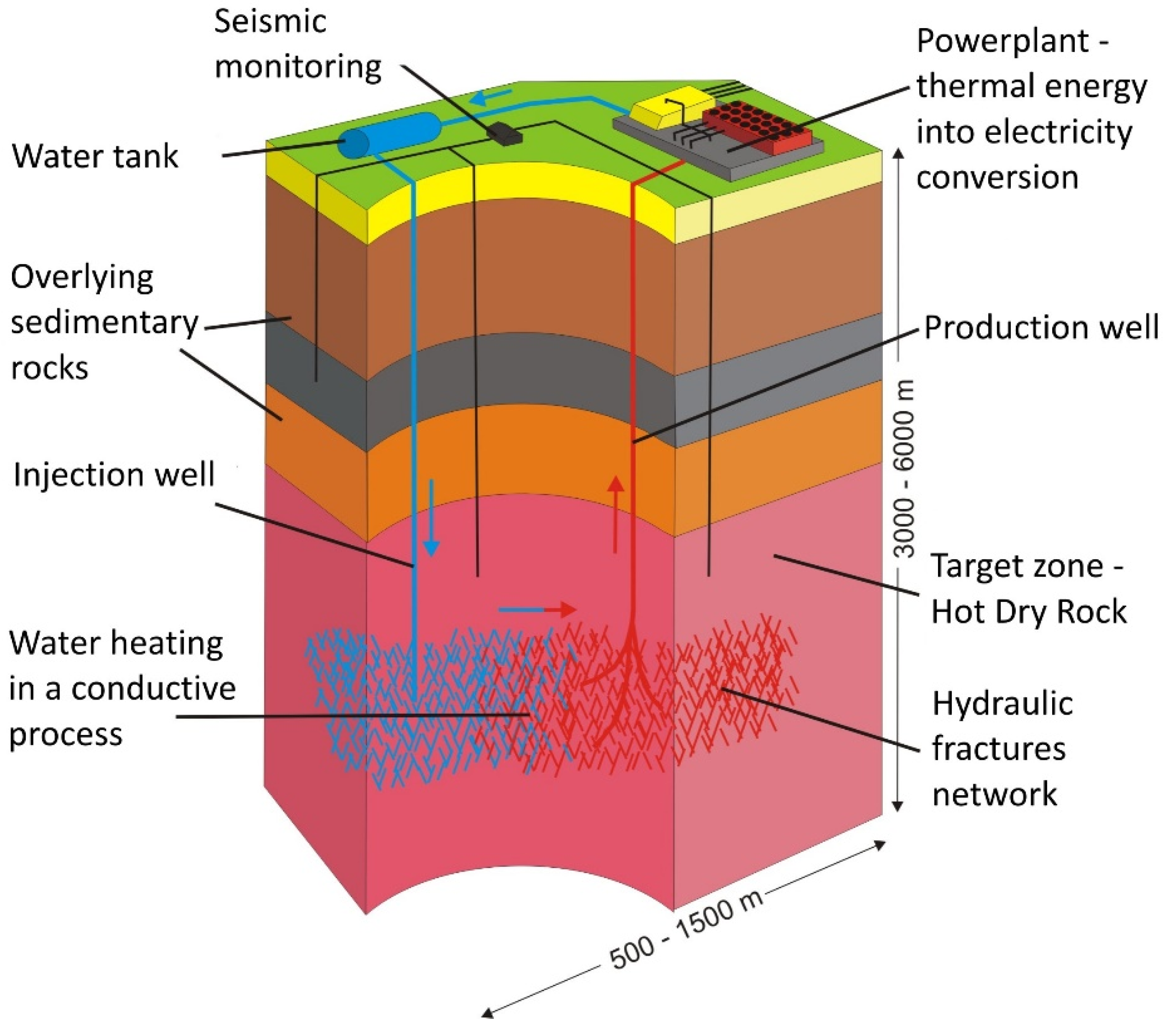
1. Introduction
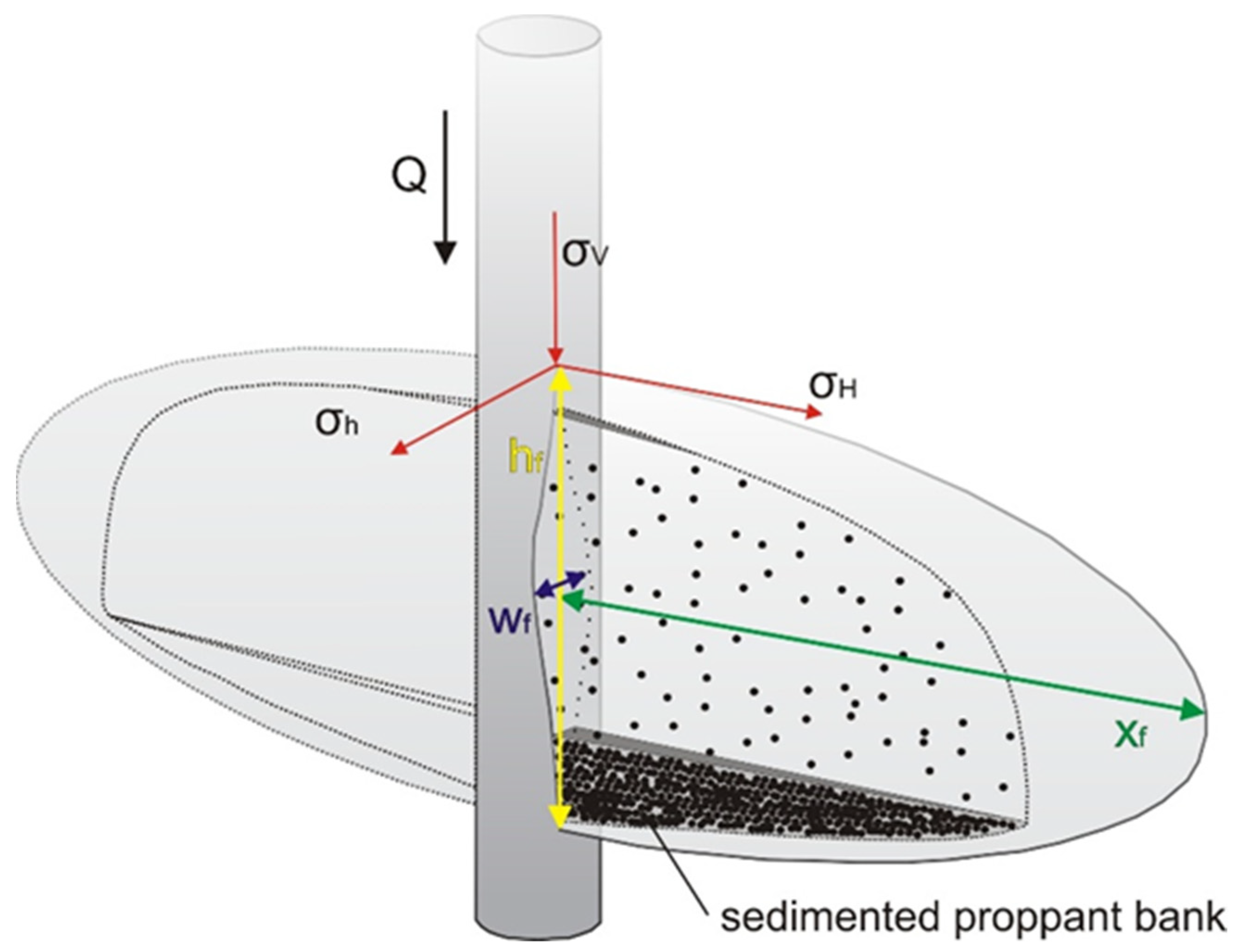
2. Hydraulic Method of Stimulation Low-Permeable Reservoir


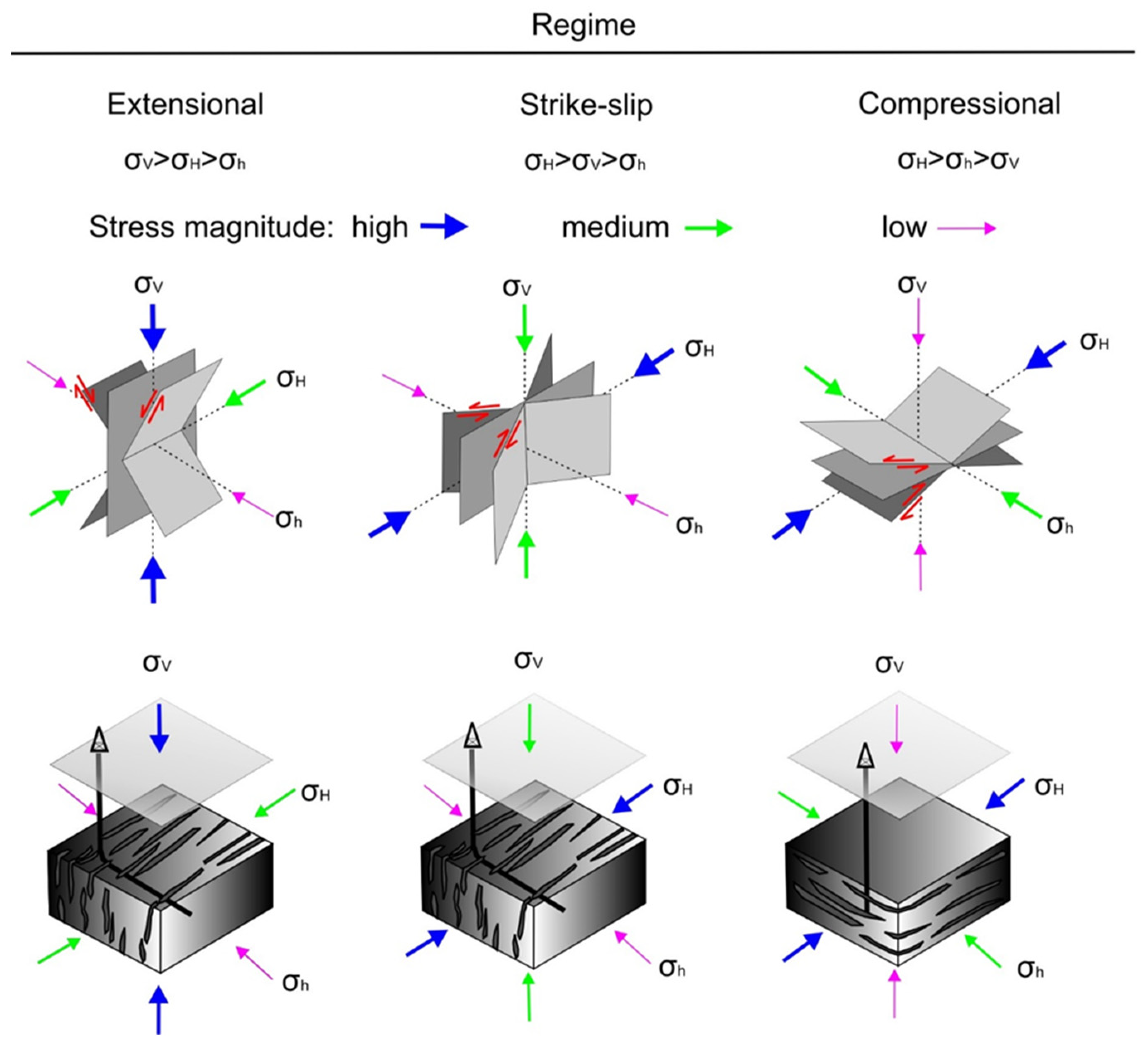
Rock Mechanics in the Design of Hydraulic Fracturing Operation
3. Literature Review
3.1. Fenton Hill (USA)
3.2. Habanero (Cooper Basin, Australia)
3.3. Rhine Graben EGS Projects
3.3.1. Soultz-sous-Forêts (France)
3.3.2. Rittershoffen (France)
3.3.3. Landau (Germany)
3.3.4. Basel (Switzerland)
3.4. GeneSys Hanower (Germany)
3.5. Groß Schönebeck (Germany)
3.6. Pohang (South Korea)
3.7. FORGE Utah (USA)
3.8. Qiabuqia (China)

| EGS Site, Activities Duration | Productive Layer Depth (m) | Temp. (°C) | Lithology, Stratigraphy | Stress Regime | Stress Magnitudes: σV, σH, σh (MPa), Pore Pressure: Pp (MPa) | Ultrasonic Velocities VP, VS (Compressional, Shear Wave) (m/s), Elastic Parameters: Young’s Modulus E (GPa), Poisson’s Ratio v (-) | Fracturing Fluid | Estimated Fracture Dimensions: l—Half Length (m), h—Height (m), w—Width (mm) |
|---|---|---|---|---|---|---|---|---|
| Fenton Hill (USA) 1974–1995 | About 4400 [EE-2 well] [16] | 327 at 4390 m [16] | Core samples from EE-2 well: granodiorite, gneiss [31] | Strike-slip/normal [32] | Estimated gradients: σV = σH—25 MPa/km, σh—13–19 MPa/km, PP—10 MPa/km [32] | 3-axial lab test, confining: 20 MPa EE-2 core, 3916 m depth: E—15–22, v—0.12–0.17. 4102 m depth: E—33, v—0.12–0.22 [31] | MHF—fresh water [32] | |
| Habanero Cooper Basin (Australia) 2003–2016 | About 4400 [33] | 248.5 [33] | Syenogranite, medium and coarse-grained [34] | Strike-slip (overlay); reverse, over-thrust (batholith target zone) [35] | At 4267 m σV—97.9 σH—150.9 σh—124.4 PP—73.1 [35] | From modeling at 3657 m TVD: E—65, v—0.25 [36]. From logging at 3674 m (granite) VP—5525 [44] | Mostly fresh water [33], water, NaCl- and NaBr-based brine [34] | |
| Rhine Graben EGS projects (Western Europe): Soultz-sous-Forêts, 90-present Landau, 2005/6-present Rittershoffen, 2013-present | Soultz 5200 [39] Landau 2200 [42] Ritters. 2200 [44] | Soultz about 200 [39] Landau about 160 [42] Ritters. about 170 [44] | Porphyric granites MFK, two-mica granites. Carboniferous [41] | Mixed, normal and strike-slip [44] | At 2200 m: σV—54.8 σV> or <σH σh—29.6 PP—22.5; calculated, based on equations from [47] | Estimated E for pure granite at the target zone—up to 80 GPa, at the zones of increased hydraulic conductivity, and clay content may be significantly lower. [70] | Soultz—frac initiation: brine, then MHF—fresh water [42] Rittershoffen—MHF: water without proppant [5] | |
| GeneSys Hannower (Germany) 2005–2013 | 3834 [52] | 169 [52] | Low permeable Buntsandstein sediments, Permian [50,52] | Normal [52] | σh—72–83, σh = 0.9 SV [52] | From lab tests and log, sandstones: E—45–65, v—0.19–0.22; clays: E—49, v—0.23 [52] | Fresh water [52] | l—1320 h—430 w—21 [52] |
| Groß Schönebeck (Germany), 2006-present | About 4100 [57] | 149 at 4285 m [54] | Clastic and volcanic rock (rhyolite, andesite) Rotliegend, Permian [2] | Normal—strike-slip σh ≥ 0.55 σV, σH ≤ 0.78–1.00 σV 57] | σV—100, σH—78–100, σh—55 [57] PP—44.9 at 4220 m [54] | Volcanic rocks: E—55 v—0.20 Sediments: E—55 v—0.18 [20] | HTU linear gel, brine, Carbo-Lt 20/40; MHF—fresh water or with quartz sand 20/40 mesh, crosslinked gel with high strength 20/40 mesh [55] | l—32 h—72 w—1.6; MHF: l—160, h—96, w—5 [55] |
| Pohang (South Korea) 2010–2017 | About 4200 [17] | 140 at 4209 m [17] | Laminated Granodiorite, Permian [17] | Strike-slip /reverse [58] Strike-slip [71] | σV—107, σH—133–153, σh—98–119 [58] σV—110, σH—115–138, σh—81–105 [71] | VP—4336, VS—2676 Ed—44.9 (laboratory tests, atmospheric conditions); VP—5920, VS—3290 (sonic logging) [60] | Fresh water [17] | |
| FORGE Utah (USA) 2016-present | about 2300 [65] | 199 [65] | Tertiary granites, quartz monzonites, monzonites [65,66] | Normal [65] | Based on gradients [65], at a depth of 2290 m: σh—38–40, σV -59. | Granite sample from 52–21 well, 3-axial test, confining pressure 55 MPa: E -73.7, v—0.22. [72] | ||
| Qiabuqia (China) 2016/17-present | about 3700 [68] | 236 [68,73] | Middle triassic granite, Anisian [73] | Normal [69] | Based on modeling at 3700 m σV—95–100 σH—85–92, σh—68–72 [69] | E—40–56 v—0.25–0.33 [68] E—42 v—0.23 [69] | For modeling was assumed: #50 crosslinked gel with HSP 20/40 proppant [68] | l—up to 600 h—about 100 w—5 [68] |
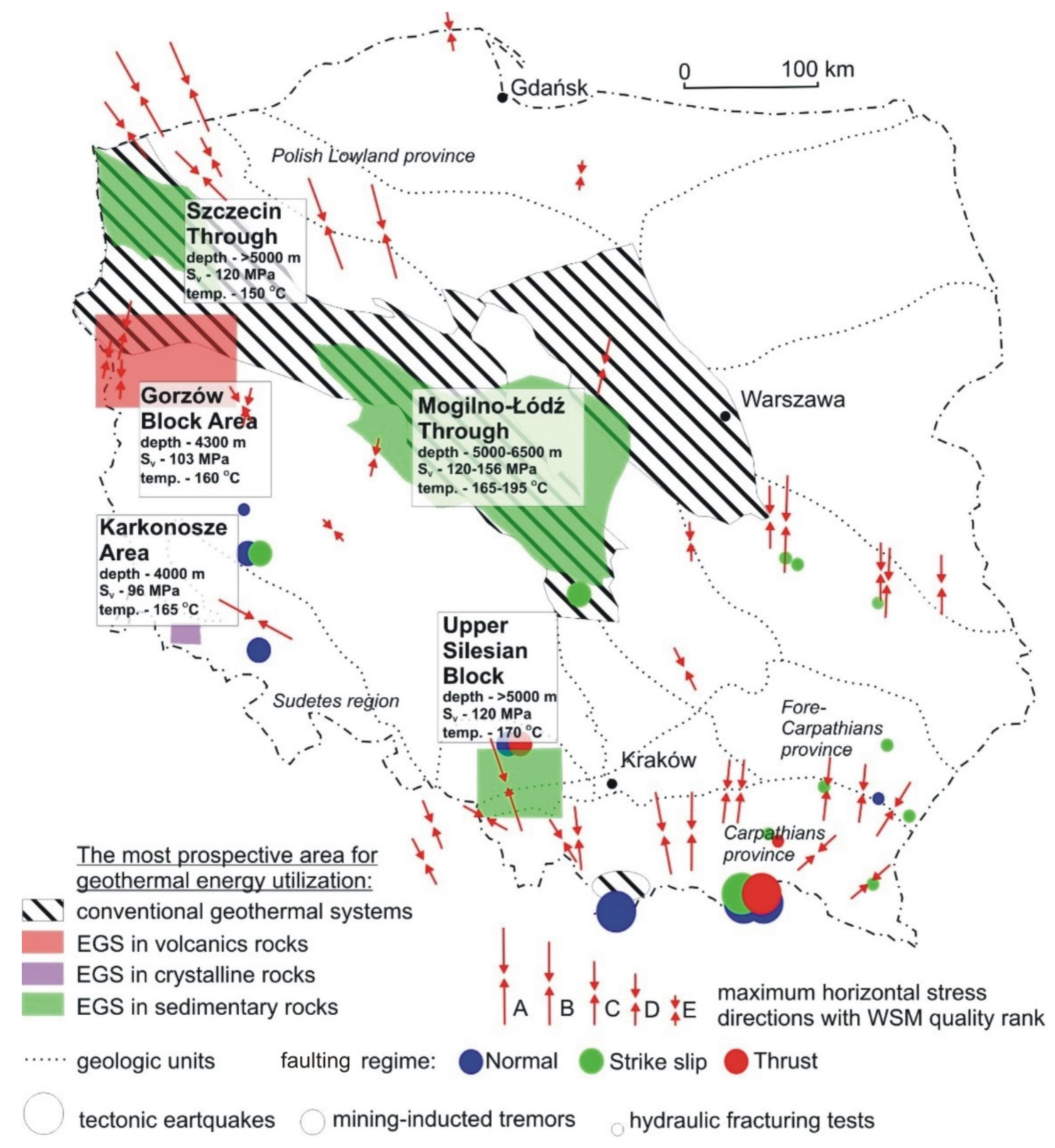
| Poland (prospective EGS areas): Karkonosze Mountains, Gorzów Block, Mogilno-Łódź Trough, Szczecin Trough Upper Silesian Block | about 4000 about 4300 about 5700 [2] about 5000 [74] about 5000 [74] | 165 153 175 [2] above 150 [74] 170 [74] | Upper Carboniferous granire, Lower Permian volcanic rocks Low-permeable Triassic sediments [2] Permian or Carboniferous sediments [74] Carboniferous sediments [74] | Western Poland—normal with strike-slip component [75,76] Upper Silesian Block—strike-slip [77] | σV: Karkonosze Mount.—96; Gorzów Block—103; Mogilno-Łódź Trough—120–153; Szczecin Trough—120; Upper Silesian Block—120. Based on assumed average rock density from [78] | Fracturing operations at this site have not been performed yet | Fracturing operations at this site have not been performed yet |
4. EGS Prospects in Poland

5. Conclusions
Author Contributions
Funding
Institutional Review Board Statement
Informed Consent Statement
Data Availability Statement
Conflicts of Interest
Nomenclature
| HF | Hydraulic fracturing |
| MHF | Massive hydraulic fracturing |
| EGS | Enhanced geothermal systems |
| HDR | Hot dry rock |
| σV | Principal vertical stress (MPa) |
| σH | Maximum horizontal stress (MPa) |
| σh | Minimum horizontal stress (MPa) |
| Pp | Pore pressure (MPa) |
| VP | Compressional wave velocity (m/s) |
| VS | Shear wave velocity (m/s) |
| E | Young’s modulus (GPa) |
| v | Poisson’s ratio (dimensionless) |
References
- Lu, S.-M. A global review of enhanced geothermal system (EGS). Renew. Sustain. Energy Rev. 2018, 81, 2902–2921. [Google Scholar] [CrossRef]
- Wójcicki, A.; Sowiżdżał, A.; Bujakowski, W. Ocena Potencjału Bilansu Cieplnego i Perspektywicznych Struktur Geologicznych dla Potrzeb Zamkniętych Systemów Geotermicznych (Hot Dry Rocks) w Polsce; Ministerstwo Środowiska: Warsaw, Poland, 2013. (In Polish) [Google Scholar]
- Zhang, H.; Wan, Z.; Elsworth, D. Failure behavior of hot-dry-rock (HDR) in enhanced geothermal systems: Macro to micro scale effects. Geofluids 2020, 2020, 8878179. [Google Scholar] [CrossRef]
- McClure, M.; Horne, R. An investigations of stimulation mechanisms in enhanced geothermal systems. Int. J. Rock Mech. Min. Sci. 2014, 72, 242–260. [Google Scholar] [CrossRef]
- Vidal, J.; Genter, A.; Schmittbuhl, J. Pre- and post-stimulation characterization of geothermal well GRT-1, Rittershoffen, France: Insights from acoustic image logs of hard fractured rock. Geophys. J. Int. 2007, 206, 845–860. [Google Scholar] [CrossRef]
- Economides, M.; Martin, T. Modern Fracturing Enhancing Natural Gas Production; ET Publishing: Houston, TX, USA, 2007. [Google Scholar]
- Brown, D.; Duchane, D.; Heiken, G.; Hriscu, V. Mining the Earth’s Heat: Hot Dry Rock Geothermal Energy; Springer: Berlin/Heidelberg, Germany, 2012. [Google Scholar]
- Hills, R.; Hand, M.; Mildren, S.; Morton, J.; Reid, P.; Reynolds, S. Hot dry rock geothermal exploration in Australia, application of the in situ stress field to hot dry rock geothermal energy in the Cooper Basin. In Proceedings of the PESA Eastern Australian Basins Symposium II, Adelaide, Australia, 19–22 September 2004. [Google Scholar]
- Schellschmidt, R.; Schultz, R.; Pester, S. Geothermal energy in Germany. In Proceedings of the World Geothermal Congress, Bali, Indonesia, 25–29 April 2010. [Google Scholar]
- Huenges, E. Geothermal Energy Systems: Exploration, Development and Utilization; Wiley-VCH: Weinheim, Germany, 2010. [Google Scholar]
- King, G. Thirty years of gas shale fracturing: What we have learned? In Proceedings of the SPE Annual Technical Conference and Exhibition, Florence, Italy, 20–22 September 2010. [Google Scholar] [CrossRef]
- Gandossi, L. An Overview of Hydraulic Fracturing and Other Formation Stimulation Technologies for Shale Gas Production; JRC Technical Reports; Publications Office of the European Union: Luxembourg, 2013. [Google Scholar] [CrossRef]
- Yildizdag, K.; Weber, F.; Konietzky, H. Hydraulic Fracturing. Available online: https://tu-freiberg.de/sites/default/files/media/professur-felsmechanik-32204/E-book/15_hydraulic_fracturing_0.pdf (accessed on 2 February 2021).
- Rafiee, M.; Soliman, M.; Pirayesh, E.; Meybodi, H. Geomechanical considerations in hydraulic fracturing designs. In Proceedings of the SPE Canadian Unconventional Resources Conference, Calgary, AB, Canada, 30 October–1 November 2012. [Google Scholar] [CrossRef]
- Kasza, P. Hydraulic fracturing in unconventional reservoirs and methods of their analysis. Prace INiG-PIB 2019, 226. (In Polish with English Abstract). [Google Scholar] [CrossRef]
- Tester, J.; Anderson, B.; Batchelor, A.; Blackwell, D.; DiPippo, R.; Drake, M.; Garnish, J.; Livesay, B.; Moore, M.; Nichols, K.; et al. The Future of Geothermal Energy—Impact of Enhanced Geothermal Systems (EGS) on the United States in the 21st Century; Massachusetts Institute of Technology: Cambridge, MA, USA; Idaho National Laboratory: Idaho Falls, ID, USA, 2006. [Google Scholar]
- Park, S.; Kim, K.-I.; Xie, L.; Yoo, H.; Min, K.-B.; Kim, M.; Yoon, B.; Kim, K.Y.; Zimmermann, G.; Guinot, F.; et al. Observations and analyses of the first two hydraulic stimulations in the Pohang geothermal development site, South Korea. Geothermics 2020, 88, 101905. [Google Scholar] [CrossRef]
- Legarth, B.; Huenges, E.; Zimmermann, G. Hydraulic fracturing in a sedimentary geothermal reservoir: Results and implications. Int. J. Rock Mech. Min. Sci. 2005, 42, 1028–1041. [Google Scholar] [CrossRef]
- Zoback, M. Reservoir Geomechanics; Cambrige University Press: Cambrige, UK, 2007. [Google Scholar] [CrossRef]
- Zimmermann, G.; Moeck, I.; Blöcher, G. Cyclic waterfrac stimulation to develop an enhanced geothermal system (EGS): Conceptual design and experimental results. Geothermics 2010, 39, 59–69. [Google Scholar] [CrossRef]
- Zimmermann, G.; Blöcher, G.; Reinicke, A.; Brandt, W. Rock specific hydraulic fracturing and matrix acidizing to enhance a geothermal system—Concepts and field results. Tectonophysics 2011, 503, 146–154. [Google Scholar] [CrossRef]
- Rickman, R.; Mullen, M.; Petre, E.; Grieser, B.; Kundert, D. A Practical use of shale petrophysics for stimulation designing optimalization: All shale plays are not clones of the Barnett Shale. In Proceedings of the SPE Annual Technical Conference and Exhibition, Denver, CO, USA, 21–24 September 2008. [Google Scholar] [CrossRef]
- Masłowski, M.; Biały, E. Studies of the embedment phenomenon in stimulation treatments. Nafta-Gaz 2016, 12, 1101–1106. [Google Scholar] [CrossRef]
- Masłowski, M.; Kasza, P.; Czupski, M.; Wilk, K.; Moska, R. Studies of fracture damage caused by the proppant embedment phenomenon in shale rock. Appl. Sci. 2019, 9, 2190. [Google Scholar] [CrossRef]
- Masłowski, M.; Labus, M. Preliminary studies on the proppant embedment in Baltic Basin shale rock. Rock Mech. Rock Eng. 2021, 54, 2233–2248. [Google Scholar] [CrossRef]
- Grieser, W.; Bray, J. Identification of production potential in unconventional reservoirs. In Proceedings of the Production and Operations Symposium, Oklahoma City, OK, USA, 1–3 April 2007. [Google Scholar] [CrossRef]
- Moska, R.; Kasza, P.; Masłowski, M. Rock anisotropy and brittleness from laboratory ultrasonic measurements in the service of hydraulic fracturing. Acta Geodyn. Geomater. 2018, 15, 1. [Google Scholar] [CrossRef]
- Moska, R.; Masłowski, M. Attempts to determine the geomechanical and Thomsen’s anisotropy parameters of coal from Upper Silesian Coal Basin area. Nafta-Gaz 2019, 11, 700–707. [Google Scholar] [CrossRef]
- Wu, H.; Zhang, P.; Dong, S.; Huang, Y.; Zhang, M. Brittleness index analysis of coal samples. Acta Geophys. 2019, 67, 789–797. [Google Scholar] [CrossRef]
- Moska, R. Brittleness index of coal from the Upper Silesian Coal Basin. Acta Geodyn. Geomater. 2021, 18, 91–101. [Google Scholar] [CrossRef]
- Duffield, R.; Nunz, G.; Smith, M.; Wilson, M. Hot Dry Rock Geothermal Energy Development Program Annual Report, Fiscal Year 1980; Los Alamos National Lab: Santa Fe, NM, USA, 1980. [Google Scholar]
- Norbeck, J.; McClure, M.; Horne, R. Field observations at the Fenton Hill enhanced geothermal system test site support mixed-mechanism stimulation. Geothermics 2018, 74, 135–149. [Google Scholar] [CrossRef]
- Wyborn, D.; da Graaf, L.; Davidson, S.; Hann, S. Development of Australia’s first hot fractured rock (HFR) underground heat exchanger, Cooper Basin, South Australia. In Proceedings of the World Geothermal Congress, Antalya, Turkey, 24–29 April 2005. [Google Scholar]
- Holl, H.-G. What Did We Learn about EGS in the Cooper Basin? Geodynamics Limited Technical Report; Geodynamics Limited: Milton, Australia, 2015. [Google Scholar] [CrossRef]
- Holl, H.-G.; Barton, C. Habanero Field—Structure and state of stress. In Proceedings of the World Geothermal Congress, Melbourne, Australia, 19–25 April 2015. [Google Scholar]
- Barton, C.; Moos, D.; Hartley, L.; Baxter, S.; Foulquier, L.; Holl, H.; Hogarth, R. Geomechanically coupled simulation of flow in fractured reservoirs. In Proceedings of the 38th Workshop on Geothermal Reservoir Engineering, Stanford, CA, USA, 11–13 February 2013. [Google Scholar]
- Hogarth, R.; Holl, H.-G. Lessons learned from the habanero EGS project. In Proceedings of the Transactions—Geothermal Resources Council, Salt Lake City, UT, USA, 2–4 October 2017. [Google Scholar]
- Australian Broadcast Corporation News. Available online: https://www.abc.net.au/news/2016-08-30/geothermal-power-plant-closes-deemed-not-financially-viable/7798962 (accessed on 4 May 2021).
- Vidal, J.; Genter, A. Overview of naturally permeable fractured reservoirs in the central and southern Upper Rhine Graben: Insights from geothermal wells. Geothermics 2018, 74, 57–73. [Google Scholar] [CrossRef]
- Cuenot, N.; Charlety, J.; Dorbath, L.; Hasser, H. Faulting mechanisms and stress tensor at the European HDR site of Soultz-Sous-Forêts. In Proceedings of the Thirtieth Workshop on Geothermal Reservoir Engineering, Stanford, CA, USA, 31 January–2 February 2005. [Google Scholar]
- Schindler, M.; Nami, P.; Schellschmidt, R.; Teza, D.; Tischner, T. Summary of hydraulic stimulation operations in the 5 km deep crystalline HDR/EGS reservoir at Soults-sous-Forets. In Proceedings of the 33th Workshop on Geothermal Reservoir Engineering, Stanford, CA, USA, 28–30 January 2008. [Google Scholar]
- Schindler, M.; Baumgärtner, J.; Gandy, T.; Hauffe, P.; Hettkamp, T.; Menzel, H.; Penzkofer, P.; Teza, D.; Tischner, T.; Wahl, G. Successful hydraulic stimulation techniques for electric power production in the Upper Rhine Graben, Central Europe. In Proceedings of the World Geothermal Congress, Bali, Indonesia, 25–29 April 2010. [Google Scholar]
- BESTEC GmbH. Available online: https://www.bestec-for-nature.com/index.php/projects-en (accessed on 19 March 2021).
- Baujard, C.; Genter, A.; Dalmais, E.; Maurer, V.; Hehn, R.; Rosillette, R.; Vidal, J.; Schmittbuhl, J. Hydrothermal characterization of wells GRT-1 and GRT-2 in Rittershoffen, France: Implications on the understanding of natural flow systems in the Rhine graben. Geothermics 2017, 65, 255–268. [Google Scholar] [CrossRef]
- Baujard, C.; Genter, A.; Maurer, V.; Dalmais, E.; Graff, J.-J.; Schmittbuhl, J. The ECOGI EGS Project in Rittershoffen, France. GRC Transactions 2014, 38, 267–270. [Google Scholar]
- Maurer, V.; Baujard, C.; Gaucher, E.; Grunberg, M.; Wodling, H.; Lehujeur, M.; Vergne, J.; Lengline, O.; Schmittbuhl, J. Seismic monitoring of the Rittershoffen project (Alsace, France). In Proceedings of the 2nd European Geothermal Workshop, Strasbourg, France, 24–25 October 2013. [Google Scholar]
- Lengline, O.; Boubacar, M.; Schmittbuhl, J. Seismicity related to the hydraulic stimulation of GRT1, Rittershoffen, France. Geophys. J. Int. 2017, 208, 1704–1715. [Google Scholar] [CrossRef]
- ES Geotermie. Available online: https://geothermie.es.fr/en/ (accessed on 13 July 2021).
- Ladner, F.; Häring, M. Hydraulic characteristics of the Basel-1 enhanced geothermal system. GRC Trans. 2009, 33, 199–204. [Google Scholar]
- Orzol, J.; Jung, R.; Jatho, R.; Tischner, T.; Kehrer, P. The GeneSys-Project: Extraction of geothermal heat from tight sediments. In Proceedings of the World Geothermal Congress, Antalya, Turkey, 24–29 April 2005. [Google Scholar]
- Tischner, T.; Evers, H.; Hauswirth, H.; Jatho, R.; Kosinowski, M.; Sulzbacher, H. New concepts for extracting geothermal energy from one well: The GeneSys project. In Proceedings of the World Geothermal Congress, Bali, Indonesia, 25–29 April 2010. [Google Scholar]
- Tischner, T.; Krug, S.; Pechan, E.; Hesshaus, A.; Jatho, R.; Bischoff, M.; Wonik, T. Massive hydraulic fracturing in low permable sedimentary rock in the Genesys project. In Proceedings of the 38th Workshop on Geothermal Reservoir Engineering, Stanford, CA, USA, 11–13 February 2013. [Google Scholar]
- Holl, H.-G.; Moeck, I.; Schandelmeier, H. Characterisation of the tectono-sedimentary evolution of a geothermal reservoir—Implications for exploitation (southern permian basin, NE Germany). In Proceedings of the Word Geothermal Congress 2005, Antalya, Turkey, 24–29 April 2005. [Google Scholar]
- Huenges, E.; Holl, H.-G.; Bruhn, D.; Brandt, W.; Saadat, A.; Moeck, I.; Zimmermann, G. Current state of the EGS project Groß Schönebeck—Drilling into the deep sedimentary geothermal reservoir. In Proceedings of the European Geothermal Congress 2007, Unterhaching, Germany, 30 May–1 June 2007. [Google Scholar]
- Blöcher, G.; Reinsch, T.; Henninges, J.; Milsch, H.; Regensprug, S.; Kummerow, J.; Francke, H.; Kranz, S.; Saadat, A.; Zimmermann, G.; et al. Hydraulic history and current state of the deep geothermal reservoir Groß Schönebeck. Geothermics 2015, 63, 27–43. [Google Scholar] [CrossRef]
- Hassanzadegan, A.; Blöcher, G.; Zimmermann, G.; Milsch, H.; Moeck, I. Induced stress in a geothermal doublet system. In Proceedings of the Thirty-Sixth Workshop on Geothermal Reservoir Engineering, Stanford, CA, USA, 31 January–2 February 2011. [Google Scholar]
- Moeck, I.; Holl, H.-G. The stress regime in Rotliegend reservoir of the Northeast German Basin. Int. J. Earth Sci. 2009, 98, 1643–1657. [Google Scholar] [CrossRef]
- Farkas, M.P.; Hofman, H.; Zimmermann, G.; Zang, A.; Bethmann, F.; Cottrell, M.; Josephson, N. Hydromechanical analysis of the second hydraulic stimulation in well PX-1. Geothermics 2021, 89, 101990. [Google Scholar] [CrossRef]
- Lee, T.J.; Song, Y. Lesson learned from low-temperature geothermal development in Pohang, Korea. In Proceedings of the 8th Asian Geothermal Symposium, Hanoi, Vietnam, 9–10 December 2008. [Google Scholar]
- Kwon, S.; Xie, L.; Park, S.; Kim, K.-I.; Min, K.-B.; Kim, K.Y.; Zhuang, L.; Choi, J.; Kim, H.; Lee, T.J. Characterization of 4.2-km-deep fractured granodiorite cores from Pohang geothermal reservoir, Korea. Rock Mech. Rock Eng. 2019, 52, 771–782. [Google Scholar] [CrossRef]
- Hofmann, H.; Zimmermann, G.; Farkas, M.; Huegenes, E.; Zang, A.; Leonhardt, M.; Kwiatek, G.; Martinez-Garzon, P.; Bonhoff, M.; Min, K.-B.; et al. First field application of cyclic soft stimulation at the Pohang Enhanced Geothermal System site in Korea. Geophys. J. Int. 2019, 217, 926–949. [Google Scholar] [CrossRef]
- Ellsworth, W.L.; Giardini, D.; Townend, J.; Ge, S.; Shimamoto, T. Triggering of the Pohang, Korea, earthquake (Mw 5.5) by enhanced geothermal system stimulation. Seismol. Res. Lett. 2019, 90, 1844–1858. [Google Scholar] [CrossRef]
- Ree, J.-H.; Kim, K.-H.; Lim, H.; Seo, W.; Kim, S.; An, X.; Kim, Y. Fault reactivation and propagation during the 2017 Pohang earthquake sequence. Geothermics 2021, 92, 102048. [Google Scholar] [CrossRef]
- Jones, C.; Moore, J.; Simmons, S. Lithology and Mineralogy of the Utah FORGE EGS Reservoir: Beaver County, Utah. GRC Trans. 2018, 42. Available online: https://publications.mygeoenergynow.org/grc/1034039.pdf (accessed on 1 September 2021).
- Moore, J.; McLennan, J.; Pankow, K.; Simmons, S.; Podgorney, R.; Wannamaker, P.; Jones, C.; Rickard, W.; Xing, P. The Utah Frontier Observatory for Research in Geothermal Energy (FORGE): A Laboratory for characterizing, creating and sustaining enhanced geothermal systems. In Proceedings of the 45th Workshop on Geothermal Reservoir Engineering, Stanford, CA, USA, 10–12 February 2020. [Google Scholar]
- Xing, P.; McLennan, J.; Moore, J. In-situ stress measurements at the Utah Frontier Observatory for Research in Geothermal Energy (FORGE) site. Energies 2020, 13, 5842. [Google Scholar] [CrossRef]
- US Departament of Energy. Available online: https://www.energy.gov/eere/forge/enhanced-geothermal-systems (accessed on 23 March 2021).
- Lei, Z.; Zhang, Y.; Yu, Z.; Hu, Z.; Li, L.; Zhang, S.; Fu, L.; Zhou, L.; Xie, Y. Exploratory research into the enhanced geothermal system power generation project: The Qiabuqia geothermal field, Northwest China. Renew. Energy 2019, 139, 52–70. [Google Scholar] [CrossRef]
- Lei, Z.; Zhang, Y.; Zhang, S.; Fu, L.; Hu, Z.; Yu, Z.; Li, L.; Zhou, J. Electricity generation from a three-horizontal-well enhanced geothermal system in the Qiabuqia geothermal field, China: Slickwater fracturing treatments for different reservoir scenarios. Renew. Energy 2020, 145, 65–83. [Google Scholar] [CrossRef]
- Meller, C.; Ledesert, B. Is there a link between mineralogy, petrophysics, and the hydraulic and seismic behaviors of the Soultz-sous-Forêts granite during stimulation? A review and reinterpretation of petro-hydromechanical data toward a better understanding of induced seismicity and fluid flow. J. Geophys. Res. Solid Earth 2017, 112, 9755–9774. [Google Scholar] [CrossRef]
- Park, S.; Xie, L.; Kim, K.-I.; Kwon, S.; Min, K.-B.; Choi, J.; Yoon, W.-S.; Song, Y. First hydraulic stimulation in fractured geothermal reservoir in Pohang PX-2 well. Procedia Eng. 2017, 191, 829–837. [Google Scholar] [CrossRef]
- US Departament of Energy. Enhanced Geothermal System Testing and Development at the Milford, Utah FORGE Site. 2016. Available online: https://www.energy.gov/sites/prod/files/2016/09/f33/Conceptual_Geologic_Model_FORGE_Milford_UT.pdf (accessed on 23 March 2021).
- Feng, J.; Zhang, Y.; Luo, J. Geology of hot dry rocks in Gonghe Basin of Qinghai-Tibet Plateau. In Proceedings of the 54th U.S. Rock Mechanics/Geomechanics Symposium, Golden, CO, USA, 28 June–1 July 2020. ARMA-2020-0011. [Google Scholar]
- Sowiżdżał, A.; Gładysz, P.; Pająk, L. Sustainable use of petrothermal resources—A review of the geological conditions in Poland. Resources 2021, 10, 8. [Google Scholar] [CrossRef]
- Jarosiński, M. Recent tectonic stress field investigations in Poland: A state of the art. Geol. Quaterly 2005, 50, 303–321. [Google Scholar]
- Zuchiewicz, W.; Badura, J.; Jarosiński, M. Neotectonics of Poland: Selected examples. Biul. Państwowego Inst. Geol. 2007, 425, 105–128, (In Polish with English Abstract). [Google Scholar]
- Jarosiński, M. Rozwarstwienie współczesnego pola naprężeń w zachodniej części polskich Karpat Zewnętrznych. Przegląd Geol. 1997, 45, 768–776. (In Polish) [Google Scholar]
- Jarosiński, M. Współczesny reżim tektoniczny w Polsce na podstawie analizy testów szczelinowania hydraulicznego ścian otworów wiertniczych. Przegląd Geol. 2005, 53, 863–872. (In Polish) [Google Scholar]
- Sapińska-Śliwa, A.; Kowalski, T.; Knez, D.; Śliwa, T.; Gonet, A.; Bieda, A. Geological and drilling aspects of construction and exploitation geothermal systems HDR/EGS. AHG Drill. Oil Gas 2015, 31, 49–62. [Google Scholar] [CrossRef][Green Version]
- Niezgoda, T.; Miedzińska, D.; Sławiński, G. Energia z głębokich pokładów gorących suchych skał (HDR). Inżynieria Bezpieczeństwa Obiektów Antropog. 2018, 3–4, 65–69. (In Polish) [Google Scholar]
- Sowiżdżał, A. Geothermal energy resources in Poland—Overview of the current state of knowledge. Renew. Sustain. Energy Rev. 2018, 82, 4020–4027. [Google Scholar] [CrossRef]
- Sowiżdżał, A.; Górecki, W.; Hajto, M. Geological conditions of geothermal resource occurrences in Poland. Geol. Q. 2020, 64, 185–196. [Google Scholar] [CrossRef]
- Górecki, W. (Ed.) Atlas of Geothermal Waters and Energy Resources in the Western Carpathians; Ministry of Environment of Poland, ZSE AGH: Krakow, Poland, 2011. [Google Scholar]
- Buła, Z.; Żaba, J. Pozycja tektoniczna Górnośląskiego Zagłębia Węglowego na tle prekambryjskiego i dolnopaleozoicznego podłoża. In Geologia i Zagadnienia Ochrony Środowiska w Regionie Górnośląskim; Jureczka, J., Buła, Z., Żaba, J., Eds.; Polish Geological Institute, Polish Geological Society: Warsaw, Poland, 2005. (In Polish) [Google Scholar]
- Różkowski, A. (Ed.) Środowisko Hydrogeochemiczne Karbonu Produktywnego Górnośląskiego Zagłębia Węglowego; Prace Naukowe Uniwersytetu Śląskiego w Katowicach; University of Silesia: Katowice, Poland, 2004. (In Polish) [Google Scholar]
- Heidbach, O.; Rajabi, M.; Cui, X.; Fuchs, K.; Muller, B.; Reinecker, J.; Reiter, K.; Tingay, M.; Wenzel, F.; Xie, F.; et al. The world stress map database release 2016: Crustal stress pattern across scales. Tectonophysics 2018, 744, 484–498. [Google Scholar] [CrossRef]
- Miecznik, M.; Sowiżdżał, A.; Tomaszewska, B.; Pająk, L. Modelling geothermal conditions in part of the Szczecin Trough—The Chociwel Area. Geologos 2015, 21, 187–196. [Google Scholar] [CrossRef]
- European Union Commission Recommendation of 22 January 2014 on Minimum Principles for the Exploration and Production of Hydrocarbons (Such as Shale Gas) Using High-Volume Hydraulic Fracturing (2014/70/EU); European Union Commission: Brussels, Belgium, 2014.
- Czupski, M.; Kasza, P.; Leśniak, Ł. Development of selective acidizing technology for an oil field in the Zechstein main dolomite. Energies 2020, 13, 5940. [Google Scholar] [CrossRef]
- Wilk, K.; Kasza, P.; Labus, K. Impact of Nitrogen Foamed Stimulation Fluids Stabilized by Nanoadditives on Reservoir Rocks of Hydrocarbon Deposits. Nanomaterials 2019, 9, 766. [Google Scholar] [CrossRef]


Publisher’s Note: MDPI stays neutral with regard to jurisdictional claims in published maps and institutional affiliations. |
© 2021 by the authors. Licensee MDPI, Basel, Switzerland. This article is an open access article distributed under the terms and conditions of the Creative Commons Attribution (CC BY) license (https://creativecommons.org/licenses/by/4.0/).
Share and Cite
Moska, R.; Labus, K.; Kasza, P. Hydraulic Fracturing in Enhanced Geothermal Systems—Field, Tectonic and Rock Mechanics Conditions—A Review. Energies 2021, 14, 5725. https://doi.org/10.3390/en14185725
Moska R, Labus K, Kasza P. Hydraulic Fracturing in Enhanced Geothermal Systems—Field, Tectonic and Rock Mechanics Conditions—A Review. Energies. 2021; 14(18):5725. https://doi.org/10.3390/en14185725
Chicago/Turabian StyleMoska, Rafał, Krzysztof Labus, and Piotr Kasza. 2021. "Hydraulic Fracturing in Enhanced Geothermal Systems—Field, Tectonic and Rock Mechanics Conditions—A Review" Energies 14, no. 18: 5725. https://doi.org/10.3390/en14185725
APA StyleMoska, R., Labus, K., & Kasza, P. (2021). Hydraulic Fracturing in Enhanced Geothermal Systems—Field, Tectonic and Rock Mechanics Conditions—A Review. Energies, 14(18), 5725. https://doi.org/10.3390/en14185725