Article

Compressor Degradation Management Strategies for Gas Turbine Aero-Engine Controller Design

by
Xiaohuan Sun
1,
Soheil Jafari
1,*,
Seyed Alireza Miran Fashandi
2 and
Theoklis Nikolaidis
1
1
Centre for Propulsion Engineering, School of Aerospace Transport and Manufacturing (SATM), Cranfield University, Bedford MK43 0AL, UK
2
Department of Mechanical Engineering, Iran University of Science and Technology, Tehran 13114-16846, Iran
*
Author to whom correspondence should be addressed.
Energies 2021, 14(18), 5711; https://doi.org/10.3390/en14185711
Submission received: 31 July 2021 / Revised: 6 September 2021 / Accepted: 7 September 2021 / Published: 10 September 2021
(This article belongs to the Special Issue Advanced Low-Carbon Technologies for Clean Energy Systems)

Abstract

:
The Advisory Council for Aeronautics Research in Europe (ACARE) Flight Path 2050 focuses on ambitious and severe targets for the next generation of air travel systems (e.g., 75% reduction in CO2 emissions per passenger kilometre, a 90% reduction in NOx emissions, and a 65% reduction in the noise emissions of flying aircraft relative to the capabilities of typical new aircraft in 2000). Degradation is an inevitable phenomenon as aero-engines age with significant impacts on the engine performance, emissions level, and fuel consumption. The engine control system is a key element capable of coping with degradation consequences subject to the implementation of an advanced management strategy. This paper demonstrates a methodological approach for aero-engine controller adjustment to deal with degradation implications, such as emission levels and increased fuel consumption. For this purpose, a component level model for an aero-engine was first built and transformed to a block-structured Wiener model using a system identification approach. An industrial Min-Max control strategy was then developed to satisfy the steady state and transient limit protection requirements simultaneously while satisfying the physical limitation control modes, such as over-speed, surge, and over-temperature. Next, the effects of degradation on the engine performance and associated changes to the controller were analysed thoroughly to propose practical degradation management strategies based on a comprehensive scientometric analysis of the topic. The simulation results show that the proposed strategy was effective in restoring the degraded engine performance to the level of the clean engine while protecting the engine from physical limitations. The proposed adjustments in the control strategy reduced the fuel consumption and, as a result, the emission level and carbon footprint of the engine.

Graphical Abstract

1. Introduction

Aero-engines degrade after operating for a period of time and, as a result, the performance indices change toward longer take-off distance and time, more fuel consumption, higher level of emissions, and lack of required thrust [1]. Among these effects, environmental considerations, such as the fuel consumption and emission levels, require specific attention respect to the ACARE Flight Path 2050 requirements for the next generation of air travel systems.
These requirements target a 75% reduction in CO2 emissions per passenger kilometre, a 90% reduction in NOx emissions, and a 65% reduction in the noise emissions of flying aircraft relative to the capabilities of typical new aircraft in 2000 [2]. In order to meet these requirements, the engine control system should be able to compensate for the environmental effects of degradation by adjusting/improving the control structure/strategy.
The engine controller is intended to satisfy all propulsion system control modes simultaneously. For this purpose, the Min-Max control strategy is widely used in the industry for aircraft engines [3,4,5,6]. It has different control loops to satisfy steady state, transient, and physical limitations control modes and can logically switch between the loops to guarantee the safe and reliable engine operation under the limitations and constraints in the transient process. For those upper boundaries, a min-select strategy is used to keep the output of these loops under upper boundaries. For those lower boundary limits, a max-select strategy is used to keep the output of these loops above the lower boundaries. The Min-Max controller is also used in the Commercial Modular Aero-Propulsion System Simulation (C-MAPSS) [7,8].
There are few studies on the strategies of the controller adjustment for degraded engines. In [9], the N-dot (derivative of the engine shaft rotational speed) strategy was used for acceleration process control, and it proved to have a faster response compared to the We/Ps3 (ratio of the fuel flow to the compressor discharge pressure) strategy when the engine degrades. However, this study did not develop a complete controller structure and did not analyse the effects of adjustment on the other engine performance parameters.
An adaptive controller tuning rule was proposed for degradation compensation by tuning the gains of the multi-mode controller in [10]. The controller was developed in the Modular Aero-Propulsion System Simulation (MAPSS). However, since the controller structure and design were not illustrated clearly, it is difficult to judge the applicability of the strategy to other types of controllers.
Some other studies focused on model-based control strategies to simplify the problem of degradation management. Luppold et al. invented a self-tuning on-board real-time model (STORM) for turbofan engines on-board modelling with degradation effects [11]. Wei et al. proposed a novel Hybrid Wiener Model (HWM) to increase the accuracy and decrease the response time of the engine model when degradation effects were taken into account [12]. However, both approaches need a set of post-flight data to be tuned, which is not a straightforward task in real-world applications.
Due to the above-mentioned fundamentally different approaches taken into account to address the degradation management challenge in aero-engines, a comprehensive Scientometric analysis is vital to guide the following research in the right direction and toward high-impact proposals. Based on such a Scientometric analysis, presented in Section 2, this paper presents a methodological approach to adjust industrial Min-Max controllers for degraded engines. This approach could be used in Min-Max controller structures for different types of gas turbine engines.
Thus, the main contribution of the paper is to propose a solution to improve the effectiveness of the degraded engine by adjusting the engine controller. For this purpose, the clean engine is first modelled by utilizing a component-level modelling approach. The developed model is then transformed into a block-structured Wiener model for the controller development. Then, a Min-Max controller strategy satisfying all engine control modes is developed in the Section 3. Section 4 illustrates the modelling of the degraded engine using health parameters.
The effects of degradation will also be presented and analysed. According to these effects, Section 5 proposes the main contribution of the manuscript, which is adjustment strategies to cope with the degradation at both the design and operation stages. The results of different strategies are analysed in Section 5, and the winning candidate will be introduced as a proposal to cope with aero-engine degradation and its consequences, such as emission and increased fuel consumption.

2. Scientometric Analysis on Aero-Engine Degradation Management

The bibliographic data includes precious information that allows researchers to assess scientific projects. This process is an indispensable part of attaining high standards in research and experimentation while enabling scholars realize the current state of various topics and distinguish their progress in different time periods [13]. Clearly, this practice provides an unparalleled understanding of scientific schemes as well as the inherent potentials and difficulties in a wide array of technical and engineering fields, thus, paving the path to increase the number and quality of publications as an indicator of a scientific institute’s position in any field [14].
Degradation is an all-important subject with consequential impacts on the efficacy of gas turbines. Therefore, the research in this area should be guided toward the right topics. Naturally, this objective can only be attained by having a thorough comprehension of this field of science as well as earlier studies. A favourite tool, in connection with the above goal, is scientometric analysis, which can show how different subjects in the field of degradation are related to each other.
This tool also shows the number of publications in any year from distinct authors/institutes [15]. The findings of this study are expected to help researchers focus on high-potential topics that have rarely been considered, set up experimental tools, apportion cost between projects, and make progress in terms of the number and quality of published articles [16].
In this study, the scientometric analysis is performed in two separate sections:
  • The first part is devoted to the scientometrics of gas turbines and degradation and accompanied by an inspection of the obtained results.
  • In the second part, a series of analyses are performed on the design of gas turbine control systems in view of degradation, followed by an evaluation of the findings.

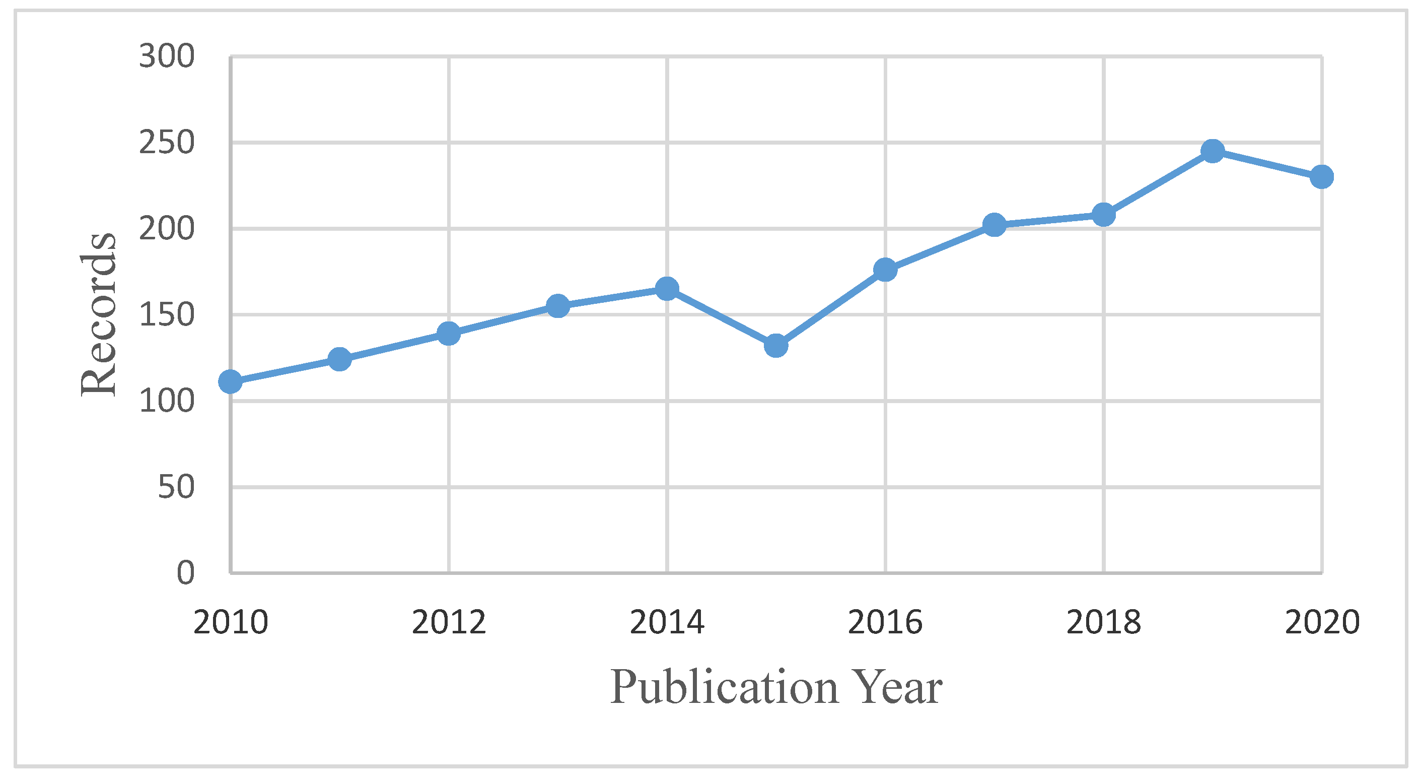
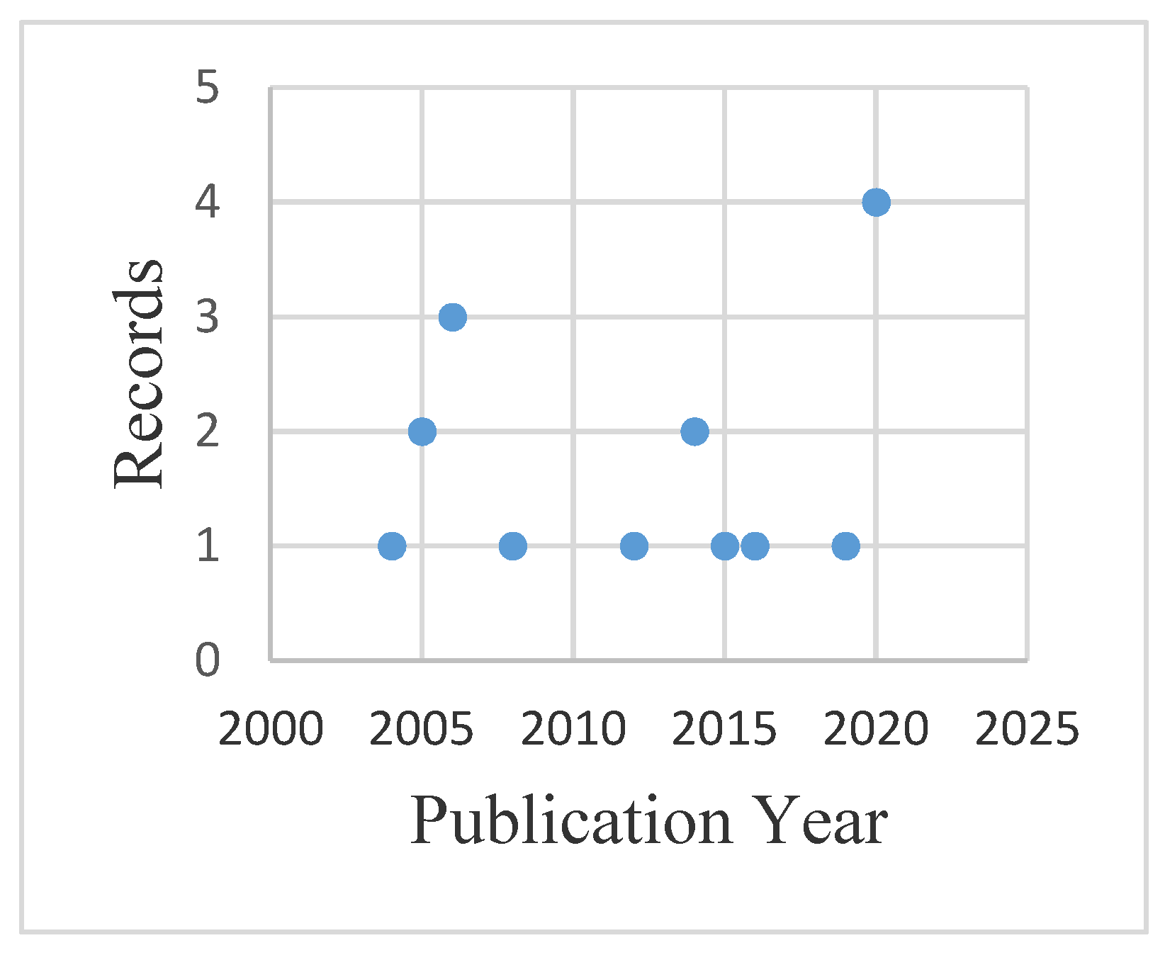
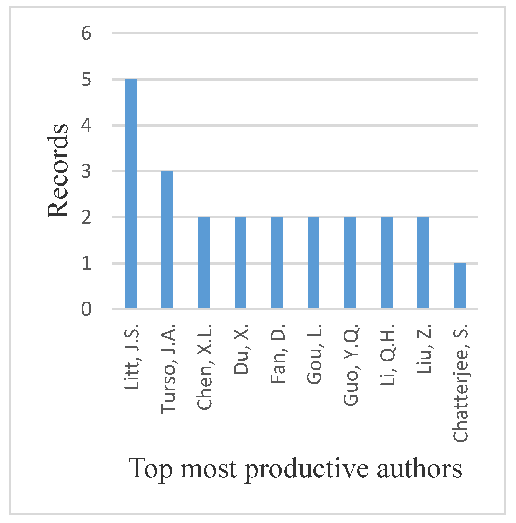
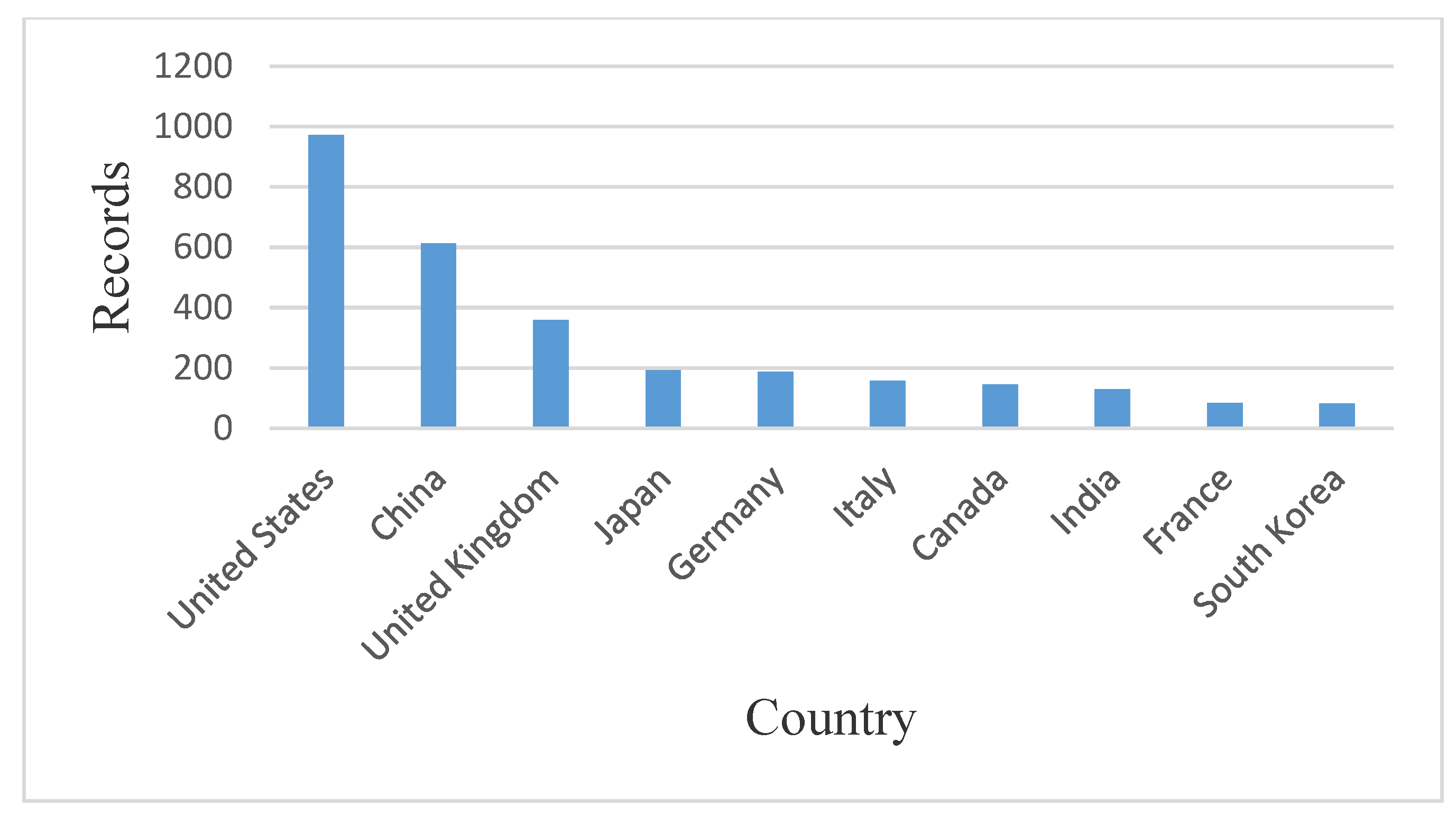
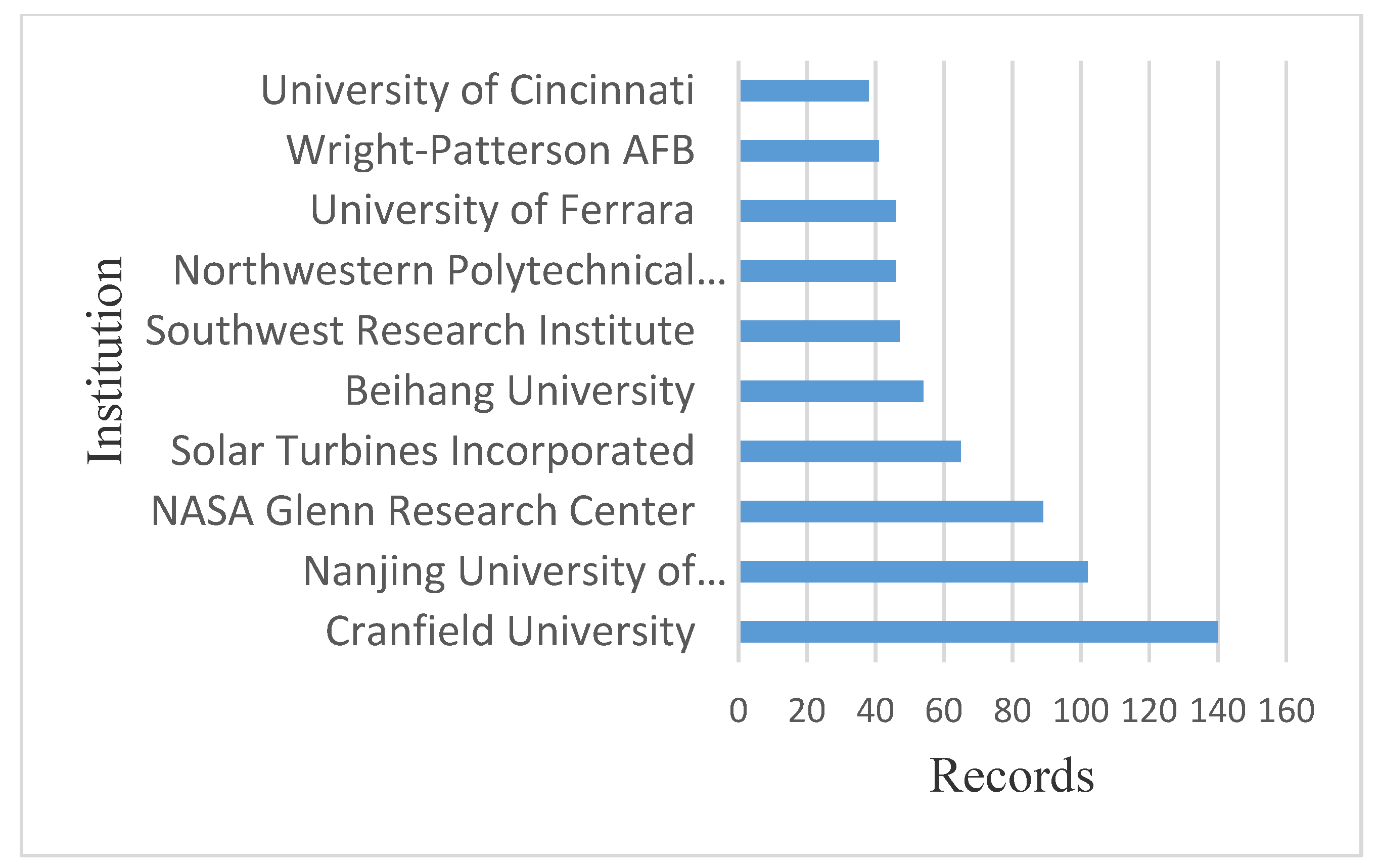
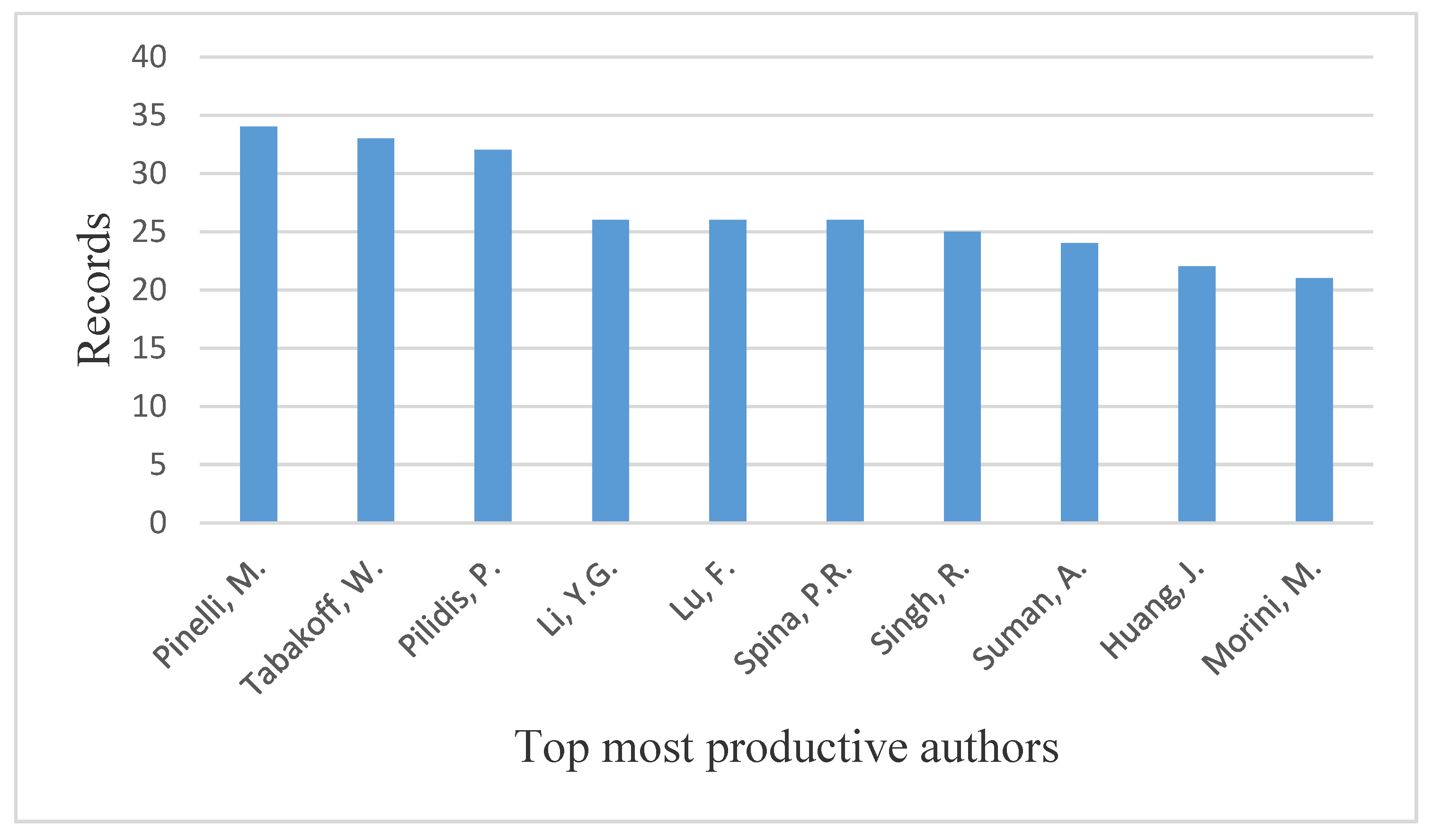
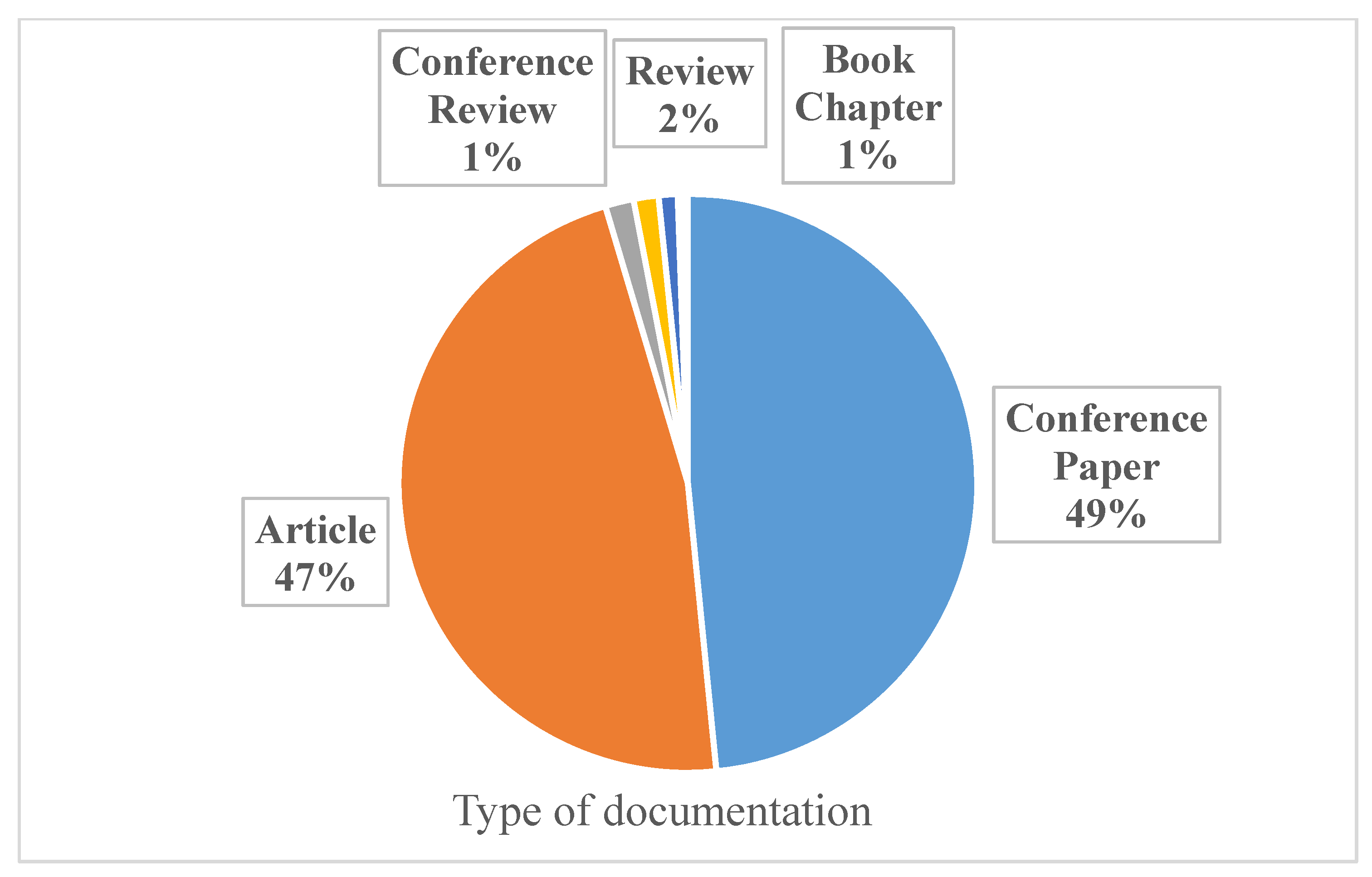
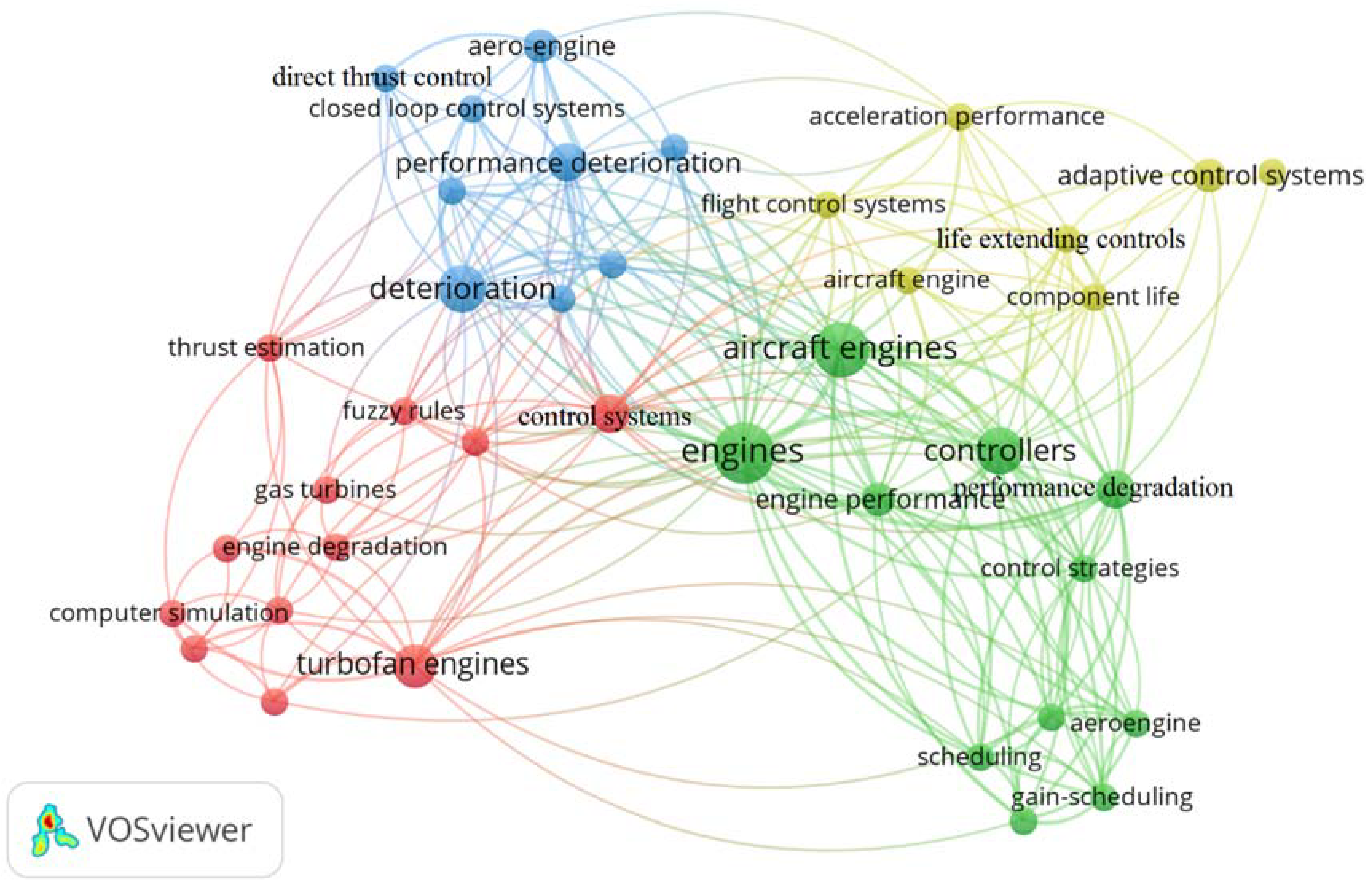
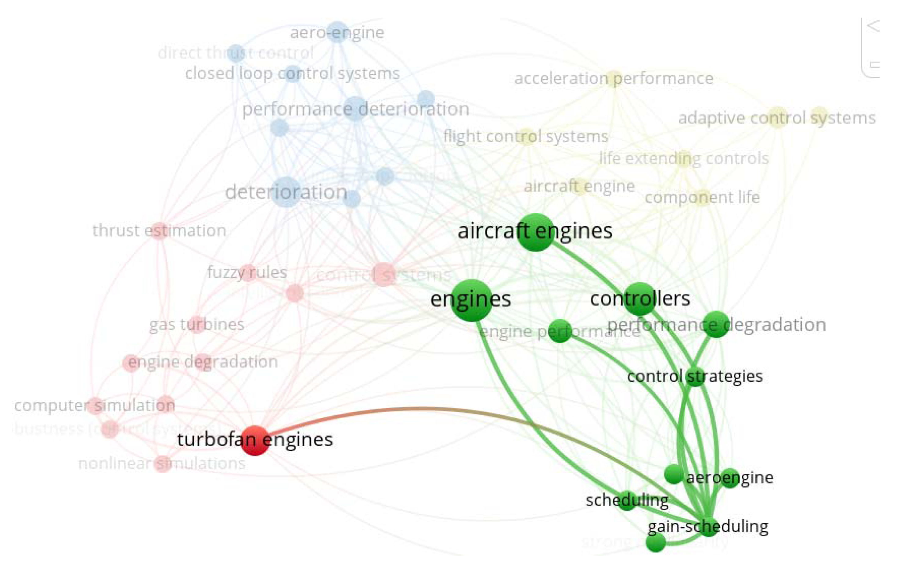
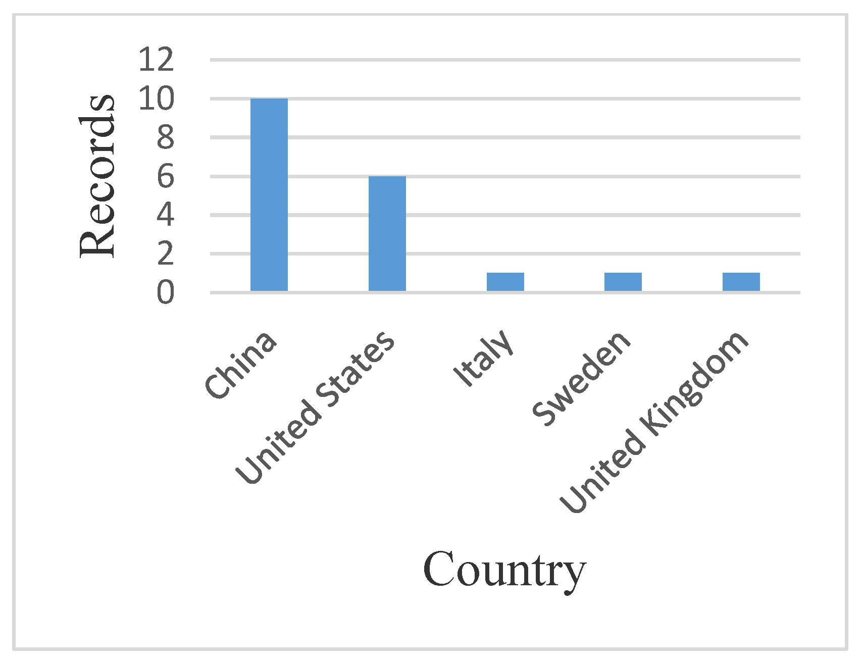
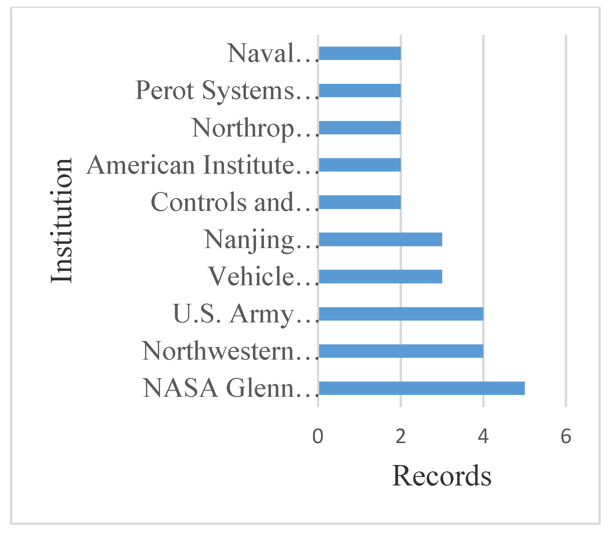
2.1. Scientometrics of Gas Turbines Degradation

In order to carry out the scientometric process, the first step is to collect information from a database. To this aim, our research relied on Scopus [17] due to its comprehensiveness in the considered area. In the next step, the design and construction of the search terms were determined so as to be able to search efficiently in Scopus [16]. A total of 3586 records were obtained in this section from the Scopus database over the interval of 1946–2021. The corresponding results are reviewed below. The most repeated terms are listed in Table 1.
These phrases refer to thematic areas related to degradation in gas turbines and aero-engines that are of great importance. These include “turbomachine blades”, “compressors”, “thermal barrier coatings”, and “performance degradation”. The control logic of a gas turbine can have a significant impact on the performance degradation. Hence, in Section 2, the scientometric analysis of the gas turbine control strategy is performed by considering degradation. Moreover, Figure 1 shows the trend in published articles between 2010 and 2020, where an increasing trend in the number of published articles can be noted from 2010 to 2014 and also from 2015 to 2019. The highest number (245 records) and the lowest number (111 records) of published articles belong to 2019 and 2010, respectively.
Figure 2 shows the top 10 countries in terms of published articles in the considered field. Among these countries, the first to third places belong to the United States (972 records), China (612 records), and the United Kingdom (359 records), respectively. Figure 3 shows the top 10 universities or scientific institutes in terms of published articles in this field. Among these institutes, the first to third rank are held by Cranfield University (140 records), Nanjing Aeronautics University (102 records), and NASA (89 records), respectively.
Figure 4 shows the top 10 authors in terms of published articles in the studied field. Among these authors, the first to third place are held by, respectively, Pinelli (34 records), Tabakoff (33 records), and Pilidis (32 records). Figure 5 shows the type of published articles in this field. As is visible in Figure 5, conference papers and original articles constitute 49% and 47% of these articles, respectively. The remaining include reviews, book chapters, etc.

2.2. Analysis and Evaluation

It should be noted that 18 records [18,19,20,21,22,23,24,25,26,27,28,29,30,31,32,33,34,35] that are directly related to the subject were obtained from the Scopus database in this section, and the results are reviewed in what follows. The most frequent words of this section are listed in Table 2, indicating that the research on this subject has been conducted on aero-engines and, in particular, turbofan engines. In addition to depicting the importance of certain items, this table demonstrates the relationship between performance degradation and other subjects, such as controllers and adaptive control systems.
Figure 6 shows the co-occurrence network of words for the subject of the strategic design of gas turbine control system while taking degradation into account. This network was drawn using VOSviewer [36] based on the Scopus data (18 records) and for terms that were repeated at least two times. A larger circle in the figure signifies a higher repetition of that word. Further, the thematic relationship of different words in the considered field can be seen in Figure 6. For example, Figure 7 displays the thematic relationship of a group of interrelated words in bold in Figure 6.
Different colours in Figure 6 classify the literature into four clusters. For each cluster, a descriptive phrase was selected to explain the research area: “direct thrust control” for the blue cluster, “gain-scheduling” for the green cluster, “thrust estimation” for the red cluster, and “life extension” for the yellow cluster. This can help researchers to better understand the applicability of publicly available approaches in the degradation management of gas turbine engines. For instance, Figure 7 shows that the gain scheduling method has been proposed for dealing with turbofan engines performance degradation. In other words, the networks presented in Figure 6 and Figure 7 give practical clues to the researchers in the field for future studies and applications.
Figure 8 shows the trends in the publication of articles from 2004 to 2020. The highest number of published articles (four records) belongs to 2020. As illustrated in Figure 1, little research has been conducted in recent years with the purpose of designing a gas turbine control strategy in view of degradation. Figure 9 shows the top five countries in the area of article publication in the considered field. Among these countries, China ranks first (10 records), the United States ranks second (six records), and the United Kingdom, Italy and Sweden rank third (one record each). Figure 10 shows the top 10 universities or scientific institutes in terms of published articles in the studied field.
Among these institutes, the first to third places respectively belong to NASA (five records), Northwestern polytechnical university (four records), and US Army research laboratory (four records). Figure 11 shows the top 10 authors in terms of published articles in the considered field. Among them, the first to third ranks are assigned to Litt (five records), Turso (three records), and Chen (two records), respectively. According to these scientometric analyses, little research has been done on the subject of this article in recent years. Thus, the proposal of this paper is timely and worth investigating.

3. Clean Engine Modelling and Control

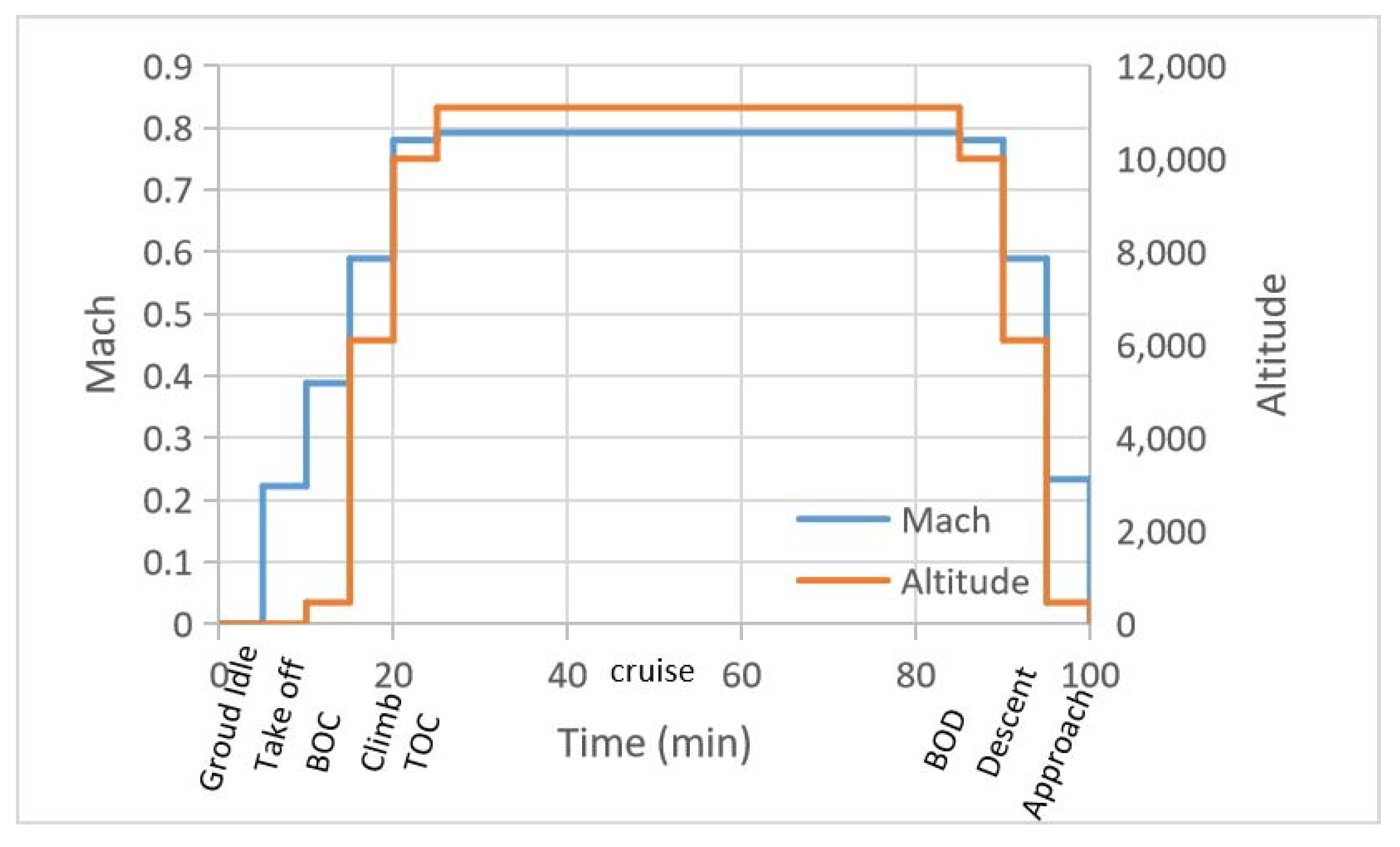
3.1. Clean Engine Modelling
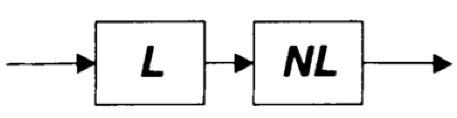
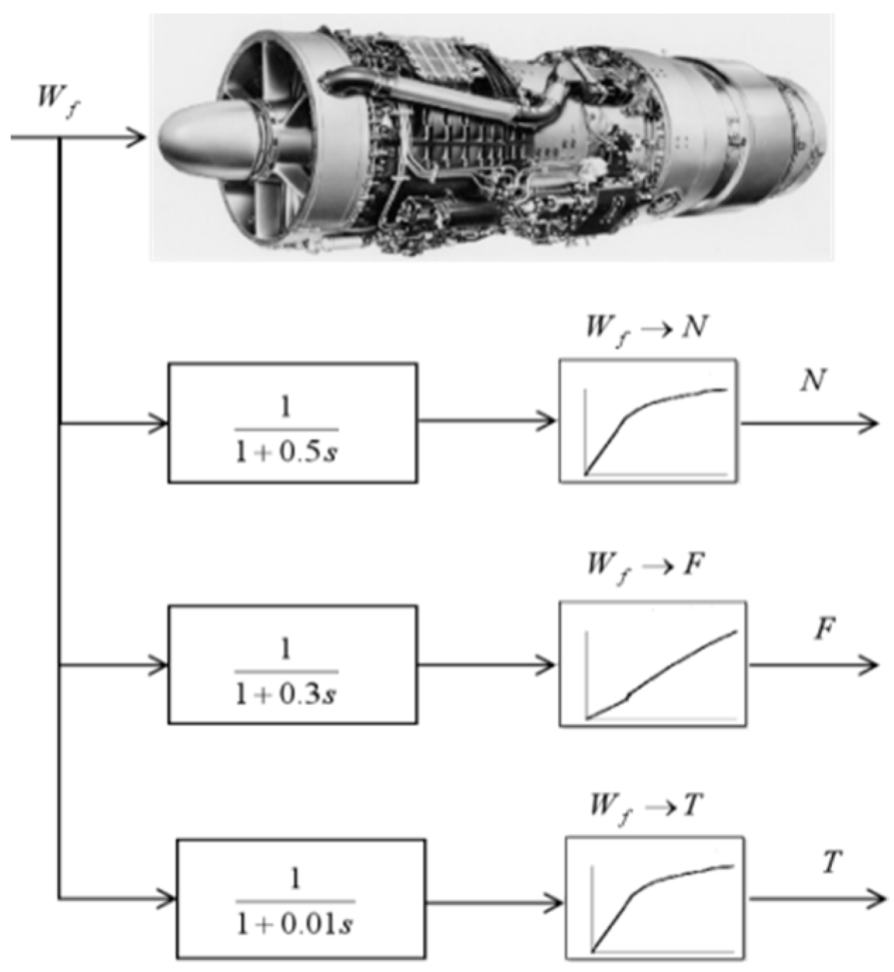
A turbojet engine with a 15-stage axial flow compressor, a cannular combustor, and a two-stage axial flow turbine was selected as the case study in this paper. The characteristics and component parameters that were chosen for modelling the engine are shown in Table 3. More details about the selected engine can be found in [37].
In order to develop a fast and accurate engine model for control purposes, a comprehensive physics-based thermodynamic model was first built by the component-level modelling approach. The simulation results of the component model were then used for system identification to develop a block-structured model for controller design. The transient process modelling for the component-level model includes the constant mass flow (CMF) method and inter-component volume (ICV) method. Since the ICV method includes air mass storage, this method is more realistic than the CMF method and is used by Turbomatch, a validated in-house software developed in Cranfield University for transient simulation [38].

3.2. Wiener Model

In [12], the Wiener model was used for aero-engine on-board modelling and was proven to be more accurate than the piecewise linear (PWL) model and novel generalized describing function (NGDF) model. The Wiener model has both a linear dynamic element and a static nonlinear part. The nonlinearity is caused by variation of the input amplitude, and it is in accord with the gas turbine model change with different fuel flow input. Therefore, the Wiener model is more suitable for the nonlinear modelling of jet engines and is used here for controller design.
The structure is as shown in Figure 12 [39]. The structure of the Wiener model consists of a linear time-invariant block (L), which reflects the time constant of the engine, and a nonlinearity block (NL), which reflects the gain of the engine. The Wiener model represents the nonlinearities for different input amplitudes. These dynamics in the Wiener model are consistent with the dynamic characteristics of gas turbine engines whose gains and response time vary with the input magnitude and operating points.
The simulation results of Turbomatch were used for system identification to be transformed to Wiener model for the controller design. Through the off-design simulation of the engine model in Turbomatch, the gains of engine parameters to fuel flow in different operating points can be obtained for the nonlinear part modelling of the Wiener model. Through transient simulation of engine model in Turbomatch, time constants of engine parameters can be calculated for the linear part modelling of the Wiener model. The architecture of the developed Wiener model for the engine is shown in Figure 13. In this figure, Wf is the fuel flow as input to the engine and N, F, and T are the rotor speed, thrust, and turbine entry temperature, respectively. These parameters will be required for the control system design and development.

3.3. Clean Engine Controller Design

In the transient process, there are different control modes that need to be satisfied to guarantee the safe operation of the engine. Primary among these are the surge control mode, which protects the engine from entering surge; the temperature limit control mode, which avoids the over-temperature of turbine blades; the rotational speed control mode, which protects the rotor from exceeding the mechanical maximum speed; and the flame-out control mode, which avoids flame out of the combustor.
The fuel flow needs to be tuned to protect the all above-mentioned control modes simultaneously. Min-Max control strategy is widely used to fulfil the set-point and limit requirements practically. Rotor speed is normally chosen for the set-point control. The transient control includes four limits: acceleration, deceleration, over-speed limit, and turbine temperature limit. The PI control law is mainly used to eliminate the steady state error. All the controllers can be expressed by the transfer function as in Equation (1):
K P ( s + K i / K P ) s
with different coefficients of gains of Kp and Ki/Kp, which are tuned using the Root Locus method. The Min-Max architecture is utilized to realize the switch of different loops to fulfil the set-point and transient limit control as shown in Figure 14. In this controller, there are four loops. The setting points are N m a x ,   N - d o t a c c ,   T 5   m a x ,   and   N - d o t d e c ;   the feedbacks are the actual rotor speed, acceleration speed or deceleration speed, and turbine outlet temperature. Using the Max and Min logic part protects the engine to work below the upper boundaries and above the lower boundaries.

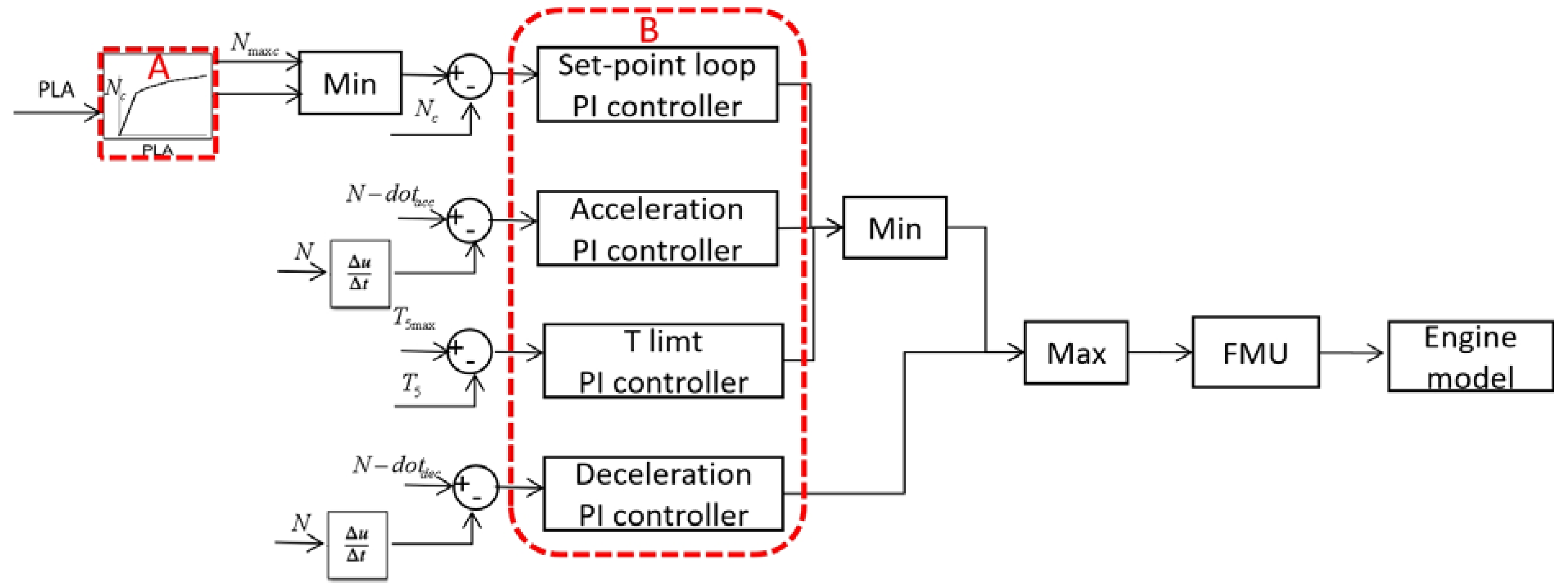
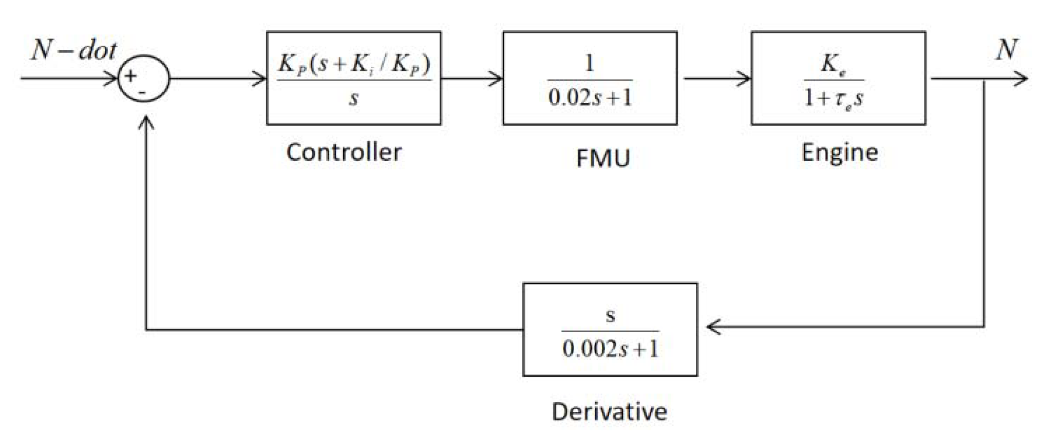
3.3.1. N-Dot Control Strategy

There are two main types of control strategies for acceleration and deceleration control. The first one refers to the fuel flow versus rotor speed. Since the relationship between the performance parameters of the degraded engine changes when the engine that uses a referred fuel flow strategy degrades, the acceleration and deceleration time will also change [40]. Another control strategy for the transient process uses the rate of rotor speed acceleration and deceleration, which is also called the N-dot control strategy. Since it has a fixed acceleration and deceleration rate, this control strategy can maintain a tight response time even in the presence of degradation.
For aero-engines, there are strict requirements for acceleration time in the safety and certification regulations. Consequently, N-dot control is a better choice from the degradation management point of view. Therefore, the N-dot control strategy is used here to maintain the response time. N-dot loops at different operating points are modelled to tune the acceleration N-dot controller. A low pass filter is also added to derivatives to avoid the high-frequency noises from the sensors in actual implementation. The block diagram for the N-dot loop is shown in Figure 15.

3.3.2. Gain Scheduling of the Controller

Since aero-engines operate in a wide range of conditions, their performance differs significantly at different operating points and flight conditions due to the nonlinearity of the aero-engine behaviour. Thus, the classical linear controller will not satisfy the performance requirements of the system, and gain scheduling should be proposed to resolve this problem.
Gain scheduling to tailor the controller gains in different operating conditions is used in aero-engine adaptive control [41]. The gains of the controller are tuned at different operating points. Through gain scheduling, different controllers are combined, and the controller adjusts its gains to the conditions according to scheduling variables. As a result, the controller parameters change at different operating points to achieve the desired performance characteristics.
Gains scheduling is adopted for set-point loop and N-dot loop, since there is a large change of the gains of the engine model at different operating points and flight conditions. For the in-hand engine model, different gains for the controller at different operating points and flight conditions are tuned, and the root locus method is used to tune the controller. In the gain scheduling of the set-point and N-dot loop, rotor speed is used as one of the scheduling variables.
Mach number and altitude influence are transferred to correction factors as another scheduling variable. A typical flight mission shown in Figure 16 [42] is used as the flight condition input. The typical thrust requirement for different flight conditions shown in Figure 17 is used for demand. The simulation results of the relative performance parameters of flight mission are shown in Figure 18.

4. Degradation Modelling

4.1. Modelling of the Degraded Engine

The degradation level of the engines can be reflected by the health condition of the components in the gas path [43]. The health condition is represented by health parameters, such as efficiency index and flow capacity index [44]. By using these indices, the degraded engine can be modelled by the component level model in the Turbomatch as follows:
η D e g r a d e d = ( 1 + Δ η ) × η Nominal
After degradation, the nonlinear part of the Wiener model will be changed because the relationship between the performance parameters has been changed, while the linear part of the Wiener model remains unchanged as it is related to the inertia of the rotor. As a result, through off-design simulation of the degraded engine model in Turbomatch, gains of the engine parameters to the fuel flow in different operating points can be obtained for the nonlinear part of the Wiener model.

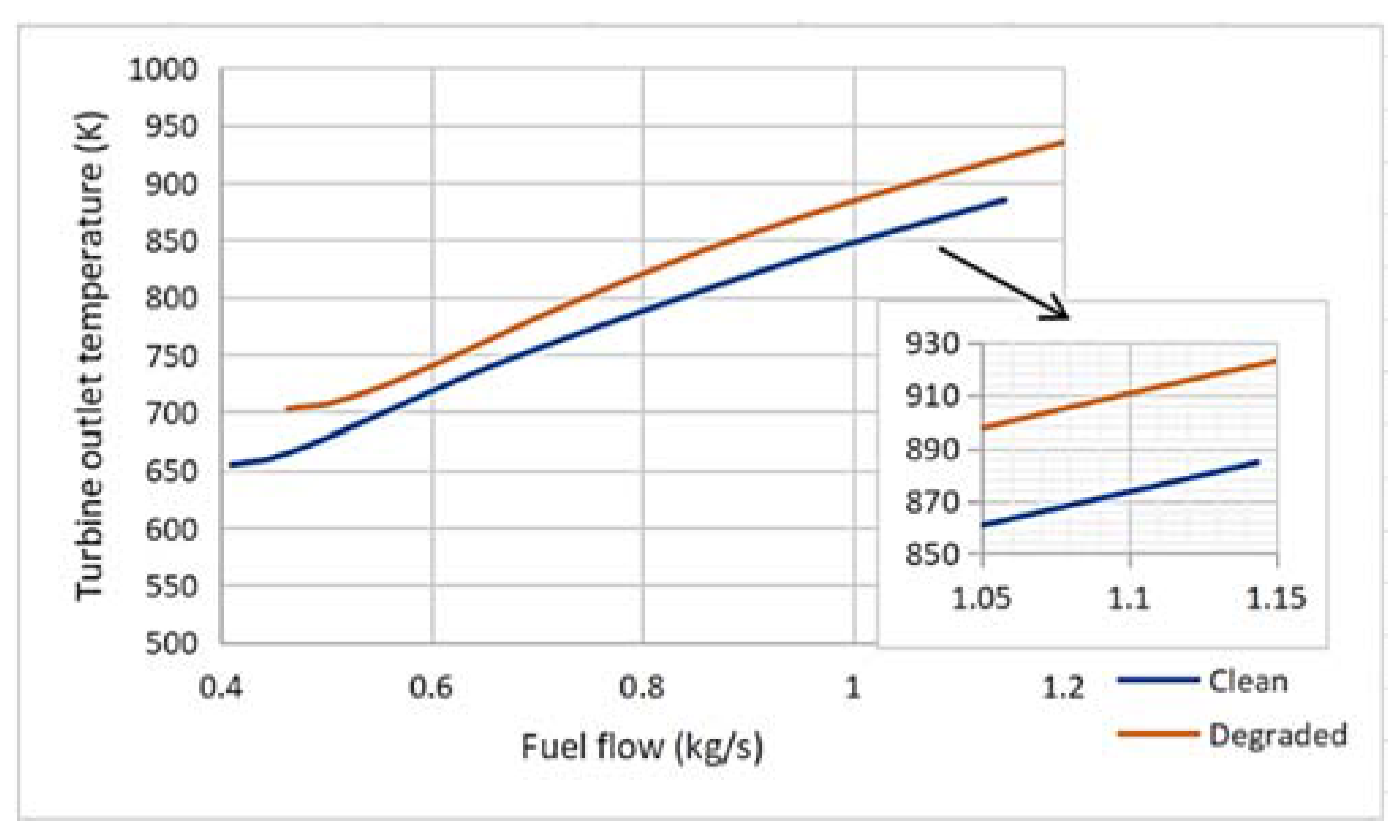
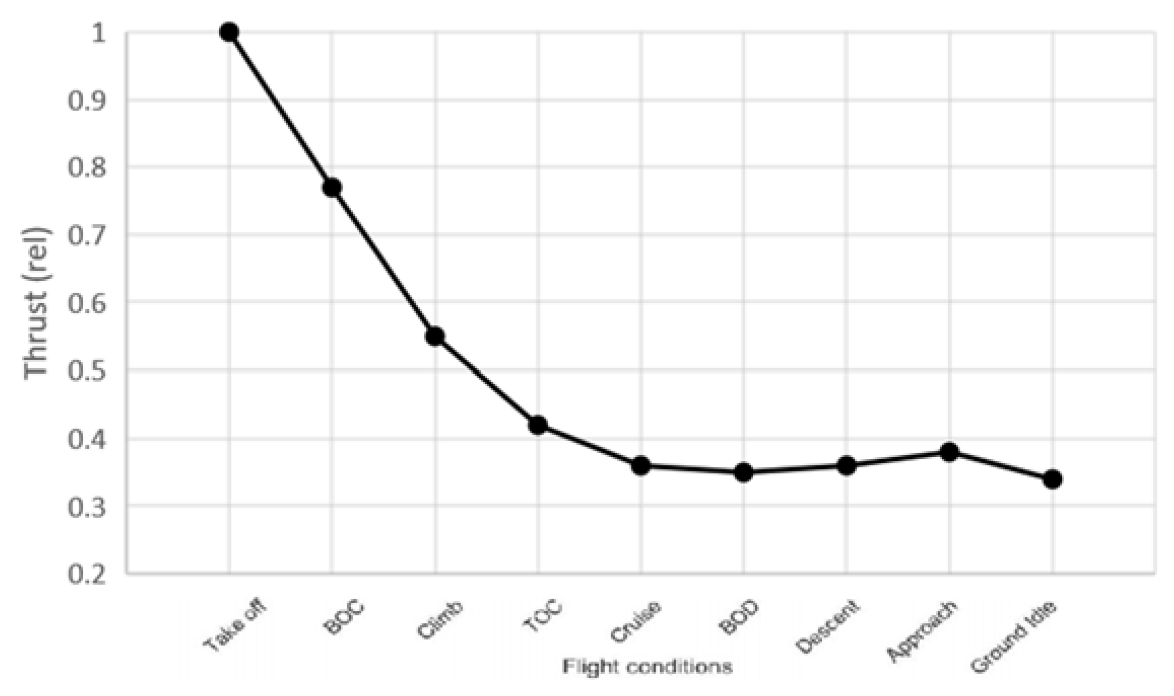
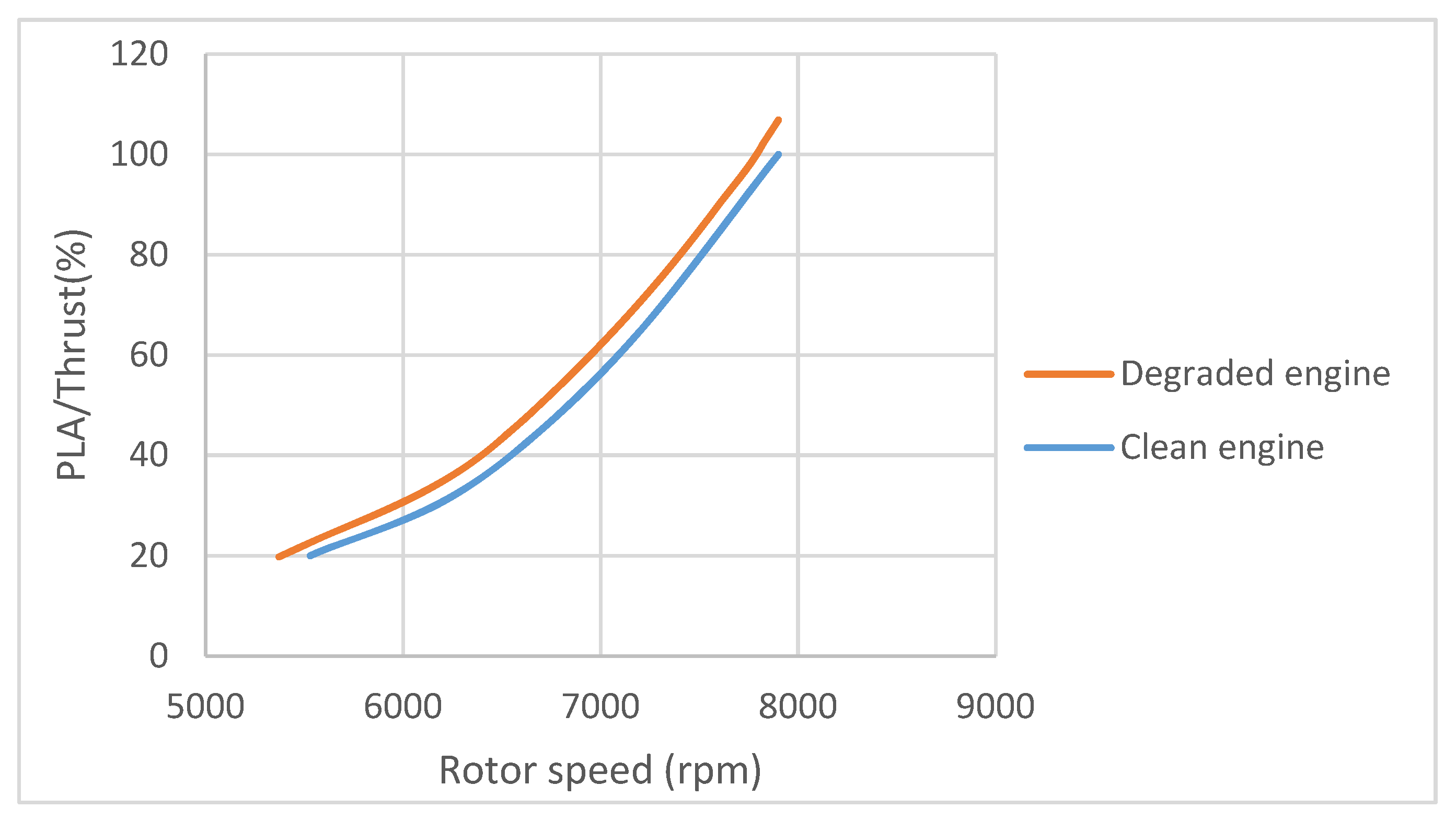
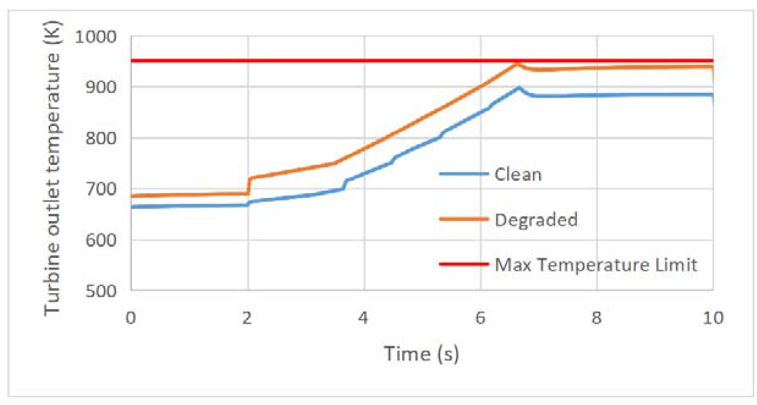
4.2. Performance Change of the Degraded Engine

A 5% compressor efficiency degradation was used for the case study. Through comparing of the simulation results of the clean engine and the degraded engine, the thrust for a given rotor speed of the degraded engine was nearly 3000 N higher (6.6%) than that of the clean engine (see Figure 19). Moreover, the rotor speed for a given fuel flow of the degraded engine was nearly 250 rpm lower than that of the clean engine (see Figure 20).
The turbine temperature for a given fuel flow of the degraded engine was nearly 40 K higher than that of the clean engine, which could be a warning sign of over-temperature and violation of physical limitations (Figure 21). In addition, the turbine temperature for a given thrust of the degraded engine was nearly 55 K higher than that of the clean engine (Figure 22).
The effects of degradation on relationships of performance parameters are summarized in Table 4. The degradation affects all engine control modes, including steady-state, transient, and physical limitations. Thus, these effects should be managed to compensate for the capability of the engine in providing the required thrust (steady-state mode) in an acceptable response time (transient mode) without violating the physical limitations. This management strategy will be developed in the next section.

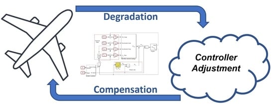
5. Degradation Management Strategies

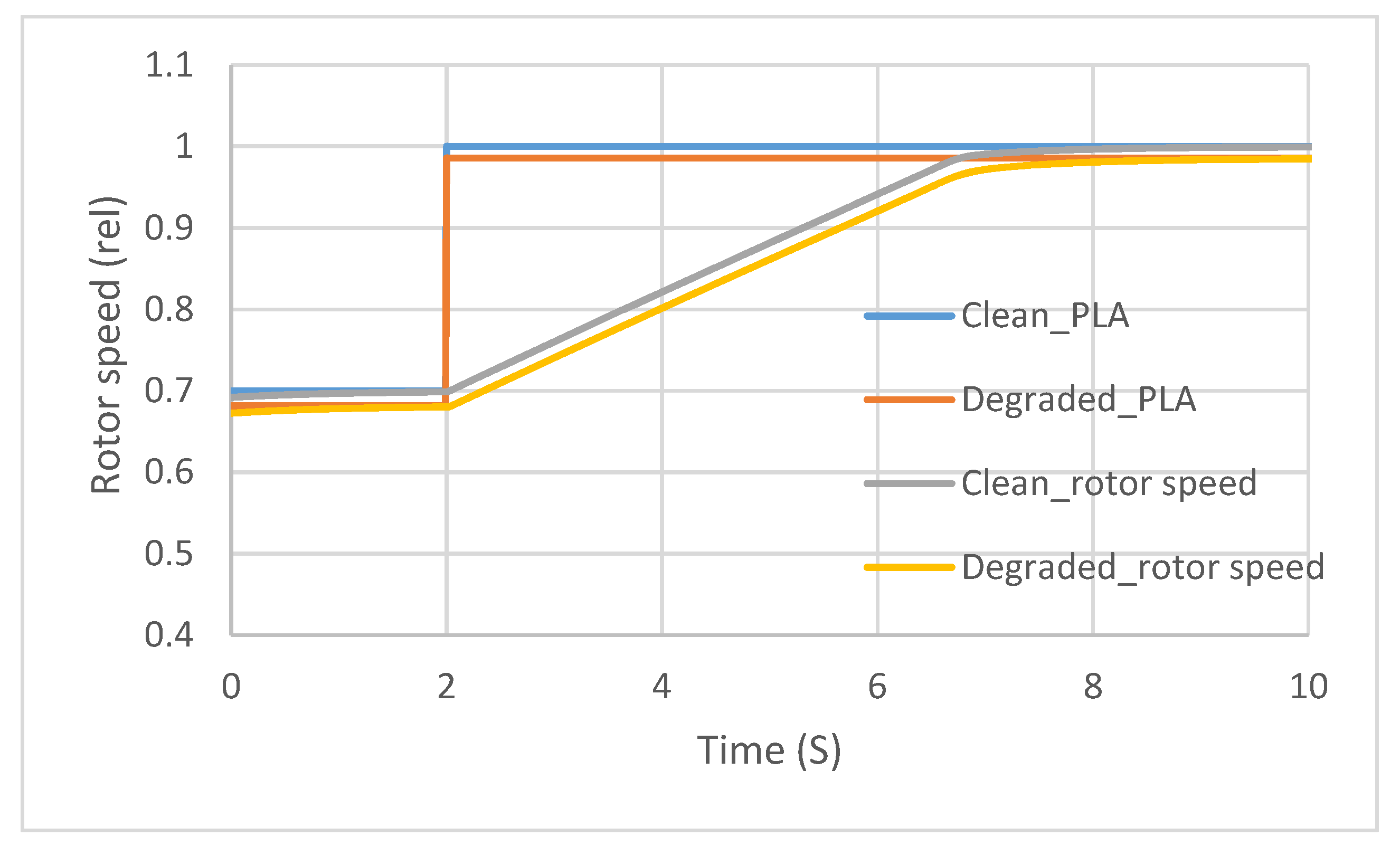
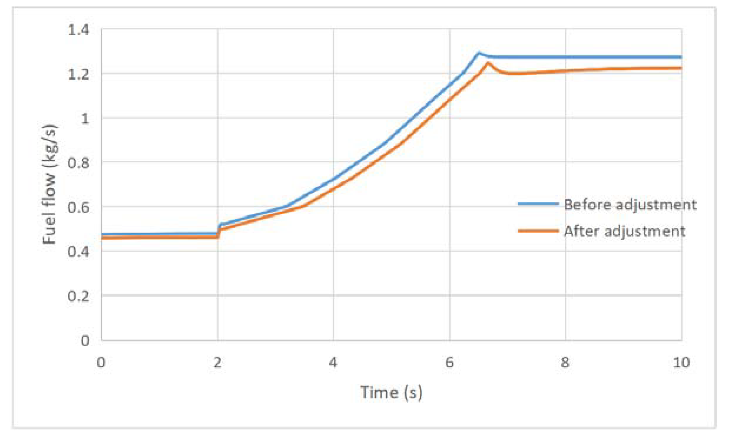
5.1. Strategies of Adjustment for the Controller of the Degraded Engine

As shown, degradation changes the relationship between rotor speed and thrust. Since PLA is related to thrust and transformed to rotor speed as the demand of the controller, the change will influence the relationship between the PLA and rotor speed demand. As a result, the relationship between PLA and rotor speed requires adjustment. The controller adjustment of the PLA to rotor speed on the controller architecture is illustrated in block A in Figure 14.
Since the engine model is changed for the degraded engine, the transfer functions for the degraded engine should also be changed. The gains of the controller for the clean engine may not satisfy the performance requirements of the degraded engine loops. Therefore, checking and adjustment of gains for the degraded engines is another strategy. At the design stage, choice of controller gains should have some margins to cope with the model changes. The model changes mainly influence the transient controller characteristics such as the overshoot percentage and settling time. Controller checking and adjustment of the gains on the controller architecture is illustrated in block B in Figure 14.
For the degraded engine, the turbine temperature and rotor speed at a given thrust will be changed. These two parameters are also the limitation demands for the turbine temperature limit loop and the over-speed loop. However, the increase of turbine temperature and rotor speed is related to the failure and life of engine. In [8], the correlation between increase of rotor speed and turbine temperature and chance of a failure was analysed.
The analysis is for the overthrust scenario with 120 percent of power, and, since the impacts are based on the increase of turbine temperature and rotor speed, the results can be referred to for the degraded engine operation with a higher turbine temperature and rotor speed. The operation time after the change of the limitation has a large impact on the chance of a failure. The change of the limitation demand is only recommended in an emergency situation, and a trade-off should be considered for the adjustment of the limitation demand. Normally, when the degradation reaches the degree that the engine needs to work beyond the limitation to satisfy the specification, maintenance should be carried out.

5.2. Adjustment for the Controller
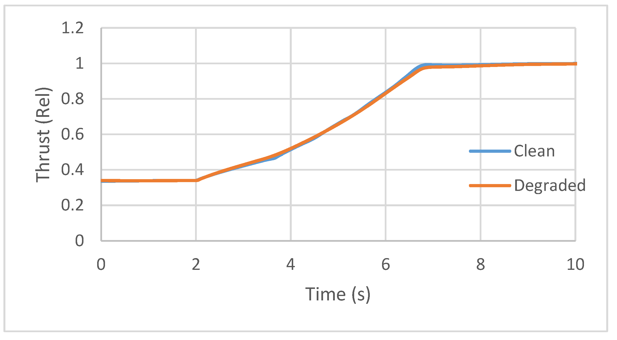
For a degraded engine with 5% compressor efficiency degradation, the following strategies should be taken to adjust the controller: the PLA to rotor speed relationship should be adjusted according to the new relationship between thrust and rotor speed of the degraded engine as in Figure 23.
The degradation effects on performance influence the transfer functions of engine models. The transfer function of performance parameters for the degraded engine in different operating points can be obtained from the Wiener model of the degraded engine. The clean controller gains are checked with the transfer function of degraded engine to check whether they can satisfy the control performance requirements. At the design stage, the design of the gains have enough margin; therefore, the gains do not need to be adjusted to fulfil the control characteristics of the system.

6. Results Analysis

The simulation results of the clean engine with the clean controller and the degraded engine with the adjusted controller with thrust demand from idle to take-off are compared in Figure 24 and Figure 25. Since the PLA to rotor speed relationship has changed, there is an offset between the rotor speed of the clean engine and the degraded engine as in Figure 24. Thanks to the effectiveness of the proposed adjustment approach, the thrust changes of the clean engine and the degraded engine are almost the same as in Figure 25.
The thrust of the clean engine is 52,628 N, and the thrust of the degraded engine with adjusted controller is 52,605 N. Thus, the adjusted controller restores thrust of the engine to the level of the clean engine perfectly (steady-state control mode satisfaction is confirmed as the relative error is less than 0.05%). Moreover, the response time of the engine from idle to 95% take-off thrust for the clean engine and degraded engine are almost the same, at 4.55 s and 4.64 s, respectively, due to the effectiveness of the N-dot control strategy (transient control mode satisfaction).
The degraded engine has a higher turbine outlet temperature compared with the clean engine. However, this value is still below the max turbine outlet temperature as shown in Figure 26, and it will not restrict the engine to achieve the required thrust (physical limitation control mode satisfaction). Figure 24, Figure 25 and Figure 26 confirm the effectiveness of the proposed approach in dealing with degradation effects in aero-engines in all aspects of control requirements including satisfaction of the required thrust, response time, and protecting the engine from malfunctions and physical limitations.
Apart from the restoration of engine performance, the fuel flow for the degraded engine controlled by the adjusted controller is less than the value tuned by the controller before adjustment as in Figure 27. This results in decreasing the fuel consumption as well as the aircraft carbon footprint.
Finally, in this paper, one type of engine and one type of degradation were investigated as the case study. Thus, future work can focus on other types of degradation and their effects on the engine performance. However, their effects will still fall into the categories classified and discussed in this paper, and the adjustment strategies could also be applied to them. The effects of different forms of degradation can also be considered simultaneously with other targets, such as different emissions and life cycle indices, to shape an engineering optimisation problem [45]. Real time adaption of the controller to the objective can also be realized by intelligent control using on-board modelling approaches [43].

7. Conclusions

In this paper, the aero-engine control system adjustment and management strategies are investigated at the design and operation stages to cope with the degradation effects. At the design stage, N-dot limitation control loop should be tuned to satisfy all engine physical limitations (including over temperature and surge margin) simultaneously. At operation stage, as the degradation affects the engine performance, an adjustment on the control strategy is required to restore the performance. It is confirmed that an adjustment of PLA to rotor speed demand is necessary to restore the performance.
Since the gains of the clean controller have sufficient margin, the gains do not need to be adjusted to fulfil the control characteristics of the system. The results show that the adjusted controller restored the thrust of the degraded engine (52,628 N for clean engine and 52,605 after adjustment) and maintained the acceleration time (4.55 s for the clean engine and 4.64 s after adjustment) while protecting the engine from over-temperature and other physical limitations. The proposed approach could be practically used to reduce the implications of aero-engine degradations particularly for increased fuel consumption and emission levels. Thus, this is a small but high-impact step toward low-carbon technology development.

Author Contributions

Conceptualization, S.J.; methodology, X.S. and S.J.; software, X.S.; validation, X.S., S.J. and T.N.; formal analysis, X.S. and S.A.M.F.; investigation, X.S.; resources, S.J.; data curation, X.S. and S.A.M.F.; writing—original draft preparation, X.S. and S.A.M.F.; writing—review and editing, S.J.; visualization, X.S.; supervision, S.J. and T.N.; project administration, X.S.; funding acquisition, S.J. All authors have read and agreed to the published version of the manuscript.

Funding

This research received no external funding.

Institutional Review Board Statement

Not applicable.

Informed Consent Statement

Not applicable.

Data Availability Statement

Not applicable.

Acknowledgments

The first author thanks the China Scholarship Council (CSC) and AECC company for funding her study at Cranfield University.

Conflicts of Interest

The authors declare no conflict of interest.

Nomenclature

FThrust
FMUFuel metering unit
N (rpm)Physical rotor speed
N c Corrected rotor speed
N - d o t a c c Acceleration N-dot demand
N - d o t d e c Deceleration N-dot demand
N max (rpm)Max rotor speed limit
PIProportional Integral
PLAPower lever angle
T 5 (K)Turbine outlet temperature
T 5 max (K)Max turbine temperature limit
η C l e a n Component efficiency of the clean engine
η D e g r a d e d Component efficiency of the degraded engine
Δ η Percent of degradation of component efficiency

References

  1. Naeem, M.; Singh, R.; Probert, D. Consequences of aero-engine deteriorations for military aircraft. Appl. Energy 2001, 70, 103–133. [Google Scholar] [CrossRef]
  2. Darecki, M.; Edelstenne, C.; Enders, T.; Fernandez, E.; Hartman, P.; Herteman, J.P.; Kerkloh, M.; King, I.; Ky, P.; Mathieu, M.; et al. Flightpath 2050, Europe’s Vision for Aviation Maintaining Global Leadership & Serving Society’s Needs; Report of the High Level Group on Aviation Research, Directorate-General for Research and Innovation Directorate-General for Mobility and Transport; Publications Office of the European Union: Brussels, Belgium, 2011. [Google Scholar]
  3. Austin Spang, H.; Brown, H. Control of jet engines. Control. Eng. Pract. 1999, 7, 1043–1059. [Google Scholar] [CrossRef]
  4. Jafari, S.; Nikolaidis, T. Meta-heuristic global optimization algorithms for aircraft engines modelling and controller design; A review, research challenges, and exploring the future. Prog. Aerosp. Sci. 2019, 104, 40–53. [Google Scholar] [CrossRef]
  5. Csank, J.; May, R.D.; Litt, J.S.; Guo, T.H. Control design for a generic commercial aircraft engine. In Proceedings of the 46th AI-AA/ASME/SAE/ASEE Joint Propulsion Conference and Exhibit, Nashville, TN, USA, 25–28 July 2010. [Google Scholar]
  6. Martin, S.; Wallace, I.; Bates, D.G. Development and validation of a civil aircraft engine simulation model for advanced controller design. J. Eng. Gas Turbines Power 2008, 130, 1–15. [Google Scholar] [CrossRef] [Green Version]
  7. Litt, J.; Frederick, D.; Guo, T.-H. The Case for Intelligent Propulsion Control for Fast Engine Response. In Proceedings of the AIAA Infotech Aerospace Conference and AIAA Unmanned. Unlimited Conference, Seattle, WA, USA, 6–9 April 2009. [Google Scholar] [CrossRef] [Green Version]
  8. Csank, J.T.; May, R.D.; Litt, J.S.; Guo, T.H. A Sensitivity Study of Commercial Aircraft Engine Response for Emergency Situations; TM-2011-217004; NASA Glenn Research Center: Cleveland, OH, USA, 2011.
  9. Dang, W.; Wang, X.; Wang, H.; Li, Z.; Li, H. Design of transient state control mode based on rotor acceleration. In Proceedings of the 2015 12th International Bhurban Conference on Applied Sciences and Technology, IBCAST 2015, Islamabad, Pakistan, 13–17 January 2015; pp. 126–132. [Google Scholar]
  10. Litt, J.S.; Parker, K.I.; Chatterjee, S. Adaptive gas turbine engine control for deterioration compensation due to aging. In Proceedings of the International Symposium on Air Breathing Engines ISABE 2003, Cleveland, OH, USA, 31 August–5 September 2003; pp. 1–9. [Google Scholar]
  11. Luppold, R.; Roman, J.; Gallops, G.; Kerr, L. Estimating in-flight engine performance variations using Kalman filter concepts. In Proceedings of the 25th Joint Propulsion Conference, Monterey, CA, USA, 12–16 July 1989. [Google Scholar] [CrossRef]
  12. Wei, Z.; Jafari, S.; Zhang, S.; Nikolaidis, T. Hybrid Wiener model: An on-board approach using post-flight data for gas turbine aero-engines modelling. Appl. Therm. Eng. 2020, 184, 116350. [Google Scholar] [CrossRef]
  13. Aryadoust, V. A review of comprehension subskills: A scientometrics perspective. System 2019, 88, 102180. [Google Scholar] [CrossRef]
  14. Mohammadi, S.J.; Fashandi, S.A.M.; Jafari, S.; Nikolaidis, T. A scientometric analysis and critical review of gas turbine aero-engines control: From Whittle engine to more-electric propulsion. Meas. Control. 2020, 54, 935–966. [Google Scholar] [CrossRef]
  15. Wuni, I.Y.; Shen, Q.; Osei-Kyei, R. Scientometric review of global research trends on green buildings in construction journals from 1992 to 2018. Energy Build. 2019, 190, 69–85. [Google Scholar] [CrossRef]
  16. Martinez, S.; Delgado, M.D.M.; Marin, R.M.; Alvarez, S. Science mapping on the environmental footprint: A scientometric analysis-based review. Ecol. Indic. 2019, 106, 105543. [Google Scholar] [CrossRef]
  17. Burnham, J.F. Scopus Database: A Review; Biomedical Digital Libraries, Springer Nature: Basingstoke, UK, 2006; Volume 3, pp. 1–8. [Google Scholar]
  18. Liu, Z.; Gou, L.; Fan, D. Aeroengine gain-scheduling control based on performance degradation with constrained control inputs. In Proceedings of the 11th International Conference on Mechanical and Aerospace Engineering (ICMAE), Athens, Greece, 14–17 July 2020; pp. 122–128. [Google Scholar] [CrossRef]
  19. Shan, R.-B.; Li, Q.-H.; Pang, S.-W.; Ni, B. Acceleration performance recovery control for degradation aero-engine. Tuijin Jishu/J. Propuls. Technol. 2020, 41, 1152–1158. [Google Scholar]
  20. Zaccaria, V.; Ferrari, M.L.; Kyprianidis, K. Adaptive control of micro gas turbine for engine degradation compensation. In Proceedings of the Turbo Expo: Power for Land, Sea, and Air. American Society of Mechanical Engineers, Phoenix, AZ, USA, 17–21 June 2019; Volume 58608, p. V003T06A004. [Google Scholar] [CrossRef]
  21. Gou, L.; Liu, Z.; Fan, D.; Zheng, H. Aeroengine robust gain-scheduling control based on performance degradation. IEEE Access 2020, 8, 104857–104869. [Google Scholar] [CrossRef]
  22. Zheng, Q.; Du, Z.; Fu, D.; Hu, Z.; Zhang, H. Direct thrust inverse control of aero-engine based on deep neural network. Int. J. Turbo Jet-Engines 2019. [Google Scholar] [CrossRef]
  23. Yonghua, W.; Keyi, J.; Tao, S.; Xinyi, Y.; Xiuxia, W. The mitigation control for engine performance deterioration. In Proceedings of the World Congress on Intelligent Control and Automation (WCICA), Guilin, China, 12–15 June 2016; pp. 280–283. [Google Scholar]
  24. Zhao, K.; Li, D.; Li, B.-W. Research on performance recovery for engine performance deterioration. Tuijin Jishu/J. Propuls. Technol. 2015, 36, 1560–1566. [Google Scholar]
  25. Guo, Y.Q.; Chen, X.L.; Du, X.; He, X.D. Adaptive life extending control of aircraft engine. In Proceedings of the 50th AI-AA/ASME/SAE/ASEE Joint Propulsion Conference, Cleveland, OH, USA, 28–30 July 2014; p. 8. [Google Scholar]
  26. Chen, X.-L.; Guo, Y.-Q.; Du, X. Adaptive life extending control of aircraft engine in whole life. Tuijin Jishu/J. Propuls. Technol. 2014, 35, 107–114. [Google Scholar]
  27. Li, Y.-B.; Li, Q.-H.; Huang, X.-H.; Zhao, Y.-P. Performance deterioration mitigation control of aero-engine. Hangkong Dongli Xuebao/J. Aerosp. Power 2012, 27, 930–936. [Google Scholar]
  28. Turso, J.A.; Litt, J.S. Toward an intelligent, deterioration accommodating controller for aging turbofan engines. Aeronaut. J. 2008, 112, 641–651. [Google Scholar] [CrossRef]
  29. Litt, J.S.; Sowers, T.S. Evaluation of an outer loop retrofit architecture for intelligent tbrbofan engine thrust control. In Proceedings of the AIAA/ASME/SAE/ASEE 42nd Joint Propulsion Conference, Sacramento, CA, USA, 9–12 July 2006; pp. 7496–7523. [Google Scholar]
  30. Fuller, J.W.; Kumar, A.; Millar, R.C. Adaptive model based control of aircraft propulsion systems: Status and outlook for naval aviation applications. In Proceedings of the Turbo Expo: Power for Land, Sea, and Air, Barcelona, Spain, 8–11 May 2006; pp. 507–513. [Google Scholar] [CrossRef]
  31. Yuan, C.-F.; Yao, H.; Liu, Y. On-board adaptive model based control of aero-engine. Tuijin Jishu/J. Propuls. Technol. 2006, 27, 354–358. [Google Scholar]
  32. Litt, J.S.; Turso, J.A.; Shah, N.; Shane Sowers, T.; Karl Owen, A. A demonstration of a retrofit architecture for intelligent control and diagnostics of a turbofan engine. In Proceedings of the InfoTech at Aerospace: Advancing Contemporary Aerospace Technologies and Their Integration, Arlington, VA, USA, 26–29 September 2005; pp. 21–38. [Google Scholar]
  33. Kurd, Z.; Kelly, T.P. Using Safety Critical Artificial Neural Networks in Gas Turbine Aero-Engine Control; Springer: Berlin, Germany, 2005; pp. 136–150. [Google Scholar]
  34. Turso, J.A.; Litt, J.S. Intelligent, robust control of deteriorated turbofan engines via linear parameter varying quadratic lyapunov function design. In Proceedings of the AIAA 1st Intelligent Systems Technical Conference, Chicago, IL, USA, 20–22 September 2004; pp. 678–691. [Google Scholar]
  35. Chatterjee, S.; Litt, J. Online model parameter estimation of jet engine degradation for autonomous propulsion control. In Proceedings of the AIAA Guidance, Navigation, and Control Conference and Exhibit, Austin, TX, USA, 11–14 August 2003. [Google Scholar] [CrossRef]
  36. van Eck, N.J.; Waltman, L. Software survey: VOSviewer, a computer program for bibliometric mapping. Scientometrics 2010, 84, 523–538. [Google Scholar] [CrossRef] [PubMed] [Green Version]
  37. Roux, E. Turbofan and Turbojet Engines: Database Handbook; Editions Elodie Roux: Blagnac, France, 2007. [Google Scholar]
  38. Pilidis, P.; Maccallum, N.R.L. A general program for the prediction of the transient performance of gas turbines. In Proceedings of the ASME 1985 International Gas Turbine Conference and Exhibit, Houston, TX, USA, 18–21 March 1985. 85-GT-209, V001T03A053. [Google Scholar] [CrossRef]
  39. Kulikov, G.G.; Thompson, H.A. Dynamic Modeling of Gas Turbines: Identification, Simulation, Condition Monitoring and Optimal Control; Springer: London, UK, 2003. [Google Scholar]
  40. Walsh, P.P.; Fletcher, P. Gas Turbine Performance, 2nd ed.; Blackwell: Oxford, UK, 2004. [Google Scholar]
  41. Richter, H. Advanced Control of Turbofan Engines; Springer: New York, NY, USA, 2012. [Google Scholar] [CrossRef]
  42. Liu, Y.; Jafari, S.; Nikolaidis, T. Advanced optimization of gas turbine aero-engine transient performance using linkage-learning genetic algorithm: Part II, optimization in flight mission and controller gains correlation development. Chin. J. Aeronaut. 2021, 34, 568–588. [Google Scholar] [CrossRef]
  43. Litt, J.S.; Simon, D.L.; Garg, S.; Guo, T.-H.; Mercer, C.; Millar, R.; Behbahani, A.; Bajwa, A.; Jensen, D.T. A survey of intelligent control and health management technologies for aircraft propulsion systems. J. Aerosp. Comput. Inf. Commun. 2004, 1, 543–563. [Google Scholar] [CrossRef] [Green Version]
  44. Li, Y.G. Gas turbine performance and health status estimation using adaptive gas path analysis. J. Eng. Gas Turbines Power 2010, 132, 1–9. [Google Scholar] [CrossRef]
  45. Saatlou, E.N.; Kyprianidis, K.; Sethi, V.; O Abu, A.; Pilidis, P. On the trade-off between minimum fuel burn and maximum time between overhaul for an intercooled aeroengine. Proc. Inst. Mech. Eng. Part G J. Aerosp. Eng. 2014, 228, 2424–2438. [Google Scholar] [CrossRef]
Figure 1. Publication trends in the field of gas turbine degradation.
Energies 14 05711 g001
Figure 2. List of top 10 countries in terms of published articles.
Energies 14 05711 g002
Figure 3. List of top 10 scientific institutes in terms of published articles.
Energies 14 05711 g003
Figure 4. List of top 10 authors in terms of published articles.
Energies 14 05711 g004
Figure 5. Type of published articles.
Energies 14 05711 g005
Figure 6. The co-occurrence network of words for Section 2.
Energies 14 05711 g006
Figure 7. The thematic relationship of a group of interrelated words.
Energies 14 05711 g007
Figure 8. Publication trends in Section 2.
Energies 14 05711 g008
Figure 9. List of the top five countries in terms of published articles.
Energies 14 05711 g009
Figure 10. List of the top 10 scientific institutes in terms of published articles.
Energies 14 05711 g010
Figure 11. List of the top 10 authors in terms of published articles.
Energies 14 05711 g011
Figure 12. Block diagram of Wiener model.
Energies 14 05711 g012
Figure 13. Wiener model for an AVON engine.
Energies 14 05711 g013
Figure 14. Architecture of a Min-Max controller.
Energies 14 05711 g014
Figure 15. Block diagram for N-Dot loop.
Energies 14 05711 g015
Figure 16. Flight conditions in a typical flight mission.
Energies 14 05711 g016
Figure 17. Thrust requirement for different flight conditions. BOC: beginning of climb; TOC: top of climb; and BOD: beginning of descent.
Energies 14 05711 g017
Figure 18. Simulation results of a flight mission.
Energies 14 05711 g018
Figure 19. Comparison of the rotor speed to thrust relationship between a clean engine and degraded engine.
Energies 14 05711 g019
Figure 20. Comparison of the fuel flow to rotor speed relationship between a clean engine and degraded engine.
Energies 14 05711 g020
Figure 21. Comparison of the fuel flow to turbine temperature relationship between a clean engine and degraded engine.
Energies 14 05711 g021
Figure 22. Comparison of the thrust to turbine temperature relationship between a clean engine and degraded engine.
Energies 14 05711 g022
Figure 23. Adjustment of the PLA to rotor speed relationship of the degraded engine.
Energies 14 05711 g023
Figure 24. Comparison of the rotor speed of the clean engine with the clean controller and the degraded engine with the adjusted controller.
Energies 14 05711 g024
Figure 25. Comparison of the thrust of the clean engine with the clean controller and the degraded engine with the adjusted controller.
Energies 14 05711 g025
Figure 26. Comparison of the turbine outlet temperature of the clean engine with the clean controller and the degraded engine with the adjusted controller.
Energies 14 05711 g026
Figure 27. Comparison of the fuel flow to the degraded engine before and after adjustment of the controller.
Energies 14 05711 g027
Table 1. Active keywords in the field of gas turbine degradation.
KeywordOccurrences
Gas Turbines1609
Aircraft Engines777
Engines581
Degradation497
Deterioration365
Turbomachine Blades364
Gases276
Compressors251
Thermal Barrier Coatings222
Performance
Degradation
221
Superalloys211
Turbine
Components
200
Oxidation188
Table 2. Active keywords in the identified records.
KeywordOccurrences
Engines10
Aircraft Engines8
Controllers6
Deterioration6
Turbofan
Engines
5
Control Systems4
Performance
Degradation
4
Performance
Deterioration
4
Adaptive Control Systems3
Aero-engine3
Engine Performance3
Table 3. Parameters chosen for the modelling of the engine.
ParametersValues
Mass flow (kg/s)77.1
Compressor pressure ratio8.8
Compressor isentropic efficiency (%)88
Combustor outlet temperature (K)1141
Turbine isentropic efficiency (%)90
Rotor speed (rpm)7900
Moment of inertia for the rotor (Nm2)20
Table 4. The effects of degradation on the performance parameters.
Performance ParametersChange (Degraded Engine to Clean Engine)Influence on the Engine
Thrust for a given rotor speed3000 N higher- Relationship between rotor speed and thrust (steady-state control mode)
- Maximum rotor speed (physical limitations control mode)
Rotor speed for a given fuel flow 250 rpm lower- Engine model of fuel flow to rotor speed (transient control mode)
Turbine outlet temperature for a given fuel flow 40 K higher- Engine model of fuel flow to turbine temperature (physical limitation control mode)
Turbine outlet temperature for a given thrust55 K higher- Maximum turbine temperature (physical limitation control mode)
Publisher’s Note: MDPI stays neutral with regard to jurisdictional claims in published maps and institutional affiliations.

