Article

Modified Dragonfly Optimisation for Distributed Energy Mix in Distribution Networks

1
Department of Electrical Engineering, Rajasthan Technical University, Kota 324010, India
2
Department of Electrical Engineering, Government Women Engineering College, Ajmer 305002, India
3
College of Engineering and Applied Science, Aston University, Birmingham B4 7ET, UK
4
James Watt School of Engineering, University of Glasgow, Glasgow G12 8QQ, UK
5
Department of Electronics and Communication, Government Engineering College, Bikaner 334004, India
*
Authors to whom correspondence should be addressed.
Energies 2021, 14(18), 5690; https://doi.org/10.3390/en14185690
Submission received: 17 August 2021 / Revised: 2 September 2021 / Accepted: 7 September 2021 / Published: 10 September 2021

Abstract

:
This article presents a two-stage optimization model aiming to determine optimal energy mix in distribution networks, i.e., battery energy storage, fuel cell, and wind turbines. It aims to alleviate the impact of high renewable penetration on the systems. To solve the proposed complex optimization model, a standard variant of the dragonfly algorithm (DA) has been improved and then applied to find the optimal mix of distributed energy resources. The suggested improvements are validated before their application. A heuristic approach has also been introduced to solve the second stage problem that determines the optimal power dispatch of battery energy storage as per the size suggested by the first stage. The proposed framework was implemented on a benchmark 33-bus and a practical Indian 108-bus distribution network over different test cases. The proposed model for energy mix and modified DA technique has significantly enhanced the operational performance of the network in terms of average annual energy loss reduction, node voltage profiles, and demand fluctuation caused by renewables.

1. Introduction

The demand for electricity as a fuel is rapidly increasing; the reason is the expansion in population and their dependency on modern technologies. As per the United Nations report on population [1], the average annual rate of population change (2015–2020) is 1.1% with a global human population of 7.9 billion (2021). Therefore, meeting the requirements while sustaining the environmental challenges has grasped the attention of ascendancy services across the globe towards renewable energy-based distribution energy resources (DERs) or distributed generators (DGs) as these are clean and prominent energy generators [2,3]. The strategic allocation of renewable based DERs in power distribution networks (PDNs) offer various technical and monetary benefits to all stakeholders, which may include reduction in carbon footprint [4], minimization of network power loss [4], maintain node voltage [5], reliability [6], power quantity [7], and reduction in investment capital [8,9,10]. Whereas the non-strategic and non-optimal integration of these DERs can cause counterproductive results [8,11,12].
However, most clean energy resources have some inherent challenges caused by its intermittent nature. High penetration of DERs can cause a threat to conventional power networks as these are not structured to sustain such a level of penetration. It may increase the network nodes voltages, particularly during the low or light load hours and increase the chance of a fault in the PDN. This high penetration may lead to the malfunction of traditional unidirectional protection devices in radial distribution networks [2,3]. Beyond these challenges, still, renewable DERs are preferred due to their ample benefits.
With immense benefits of renewable-based DERs over traditional ones have attracted the attention of various stakeholders to increase the renewable penetration in the modern distribution networks. As identified by many researchers that co-generation is the possible solution to mitigate some of the issues of intermittent generations [13,14]. The renewable co-generation plant adopts the optimal dispatch and switching base operation approach to utilize the complementary characteristics of wind and sun. However, this methodology is not self-sustained to completely overcome the stated limitations; since the predominant challenge is the excessive power generation from the intermittent power of wind turbine (WT) and solar photovoltaic (PV) during the light load hours demand. In this situation, the dispatchable DERs and energy storage systems showed a great potential to add operational flexibility during the crucial demand hours and offer virtual inertia for the network. The dispatchable DERs also assist the operators for load shifting, peak shaving operation, as well as provide cushion to the sudden deviation in power generation from the renewable DERs [8,15].
Many researchers have modeled various solutions based on the aforementioned methodologies, i.e., multiobjective multi-verse optimization algorithms for minimization of the installation cost of DERs and to improve the voltage profile simultaneously by coordinating the local and central generation units [8]. In [4], a novel model is proposed for accommodating renewable DERs for multiobjective problems, i.e., minimization of total harmonics distortion, network power losses, cost of DERs and emission of greenhouse gases, considering the various type of loads and load growth. In [16], a novel harmonic distortion level detecting technique is introduced by deploying impedance characteristics of buses, voltage limits, and harmonic current of the network. Furthermore, a model is suggested for optimal integration and operation management of WT and BESS in [2]. A study is presented in [17] for coordination of DERs and BESS and to minimize the operational cost. In [12], a framework is proposed for optimal accommodation of WT and BESS with an arrangement of central and distributed processes for the distribution network operators (DNO). Further, in [18] a multiobjective nested model is developed to deploy PV with BESS in a distribution system.
Most of the earlier works in the literature investigated the models that integrate WTs by considering a discrete power generator with small size BESS and using conversational prominent optimization techniques. However, a WT generates a fixed power and can only be deployed according to feasible sizes available in the market. Further, the large-sized BESS can be deployed in PDN as these are available in the market and will help in reducing the installation cost. Moreover, in this literature, there is a lack of effectiveness and fast power dispatchable strategies for large-sized BESSs. There is also a requirement for effective modeling of a fuel cell (FC) in PDNs for its performance enhancement. Furthermore, the optimal integration of mixed DERs is a complex, non-convex and non-linear problem that requires an efficient and robust artificial intelligence-based optimization technique.
In this paper, a novel two-stage simulation model is designed for adequate accommodation of mixed DERs such as WT, BESS, and FC with the consideration of day-to-day DNO objectives. Stage-I (outer layers) are planned to solve the multiple objectives by determining the feasible and optimal sites and corresponding sizes of various considered DERs. Whereas stage-II (inner layers) operates for the hourly objectives of optimal dispatches of BESS and FC to explore maximum benefits. The proposed model is implemented on a 33-bus benchmark and real-life 108-bus Indian distribution systems to investigate the model’s potential and efficacy. Furthermore, a modified dragonfly optimization is proposed and established before solving the designed model for DER mix. The results obtained are competitive and revealed that the suggested improvements increased the solution searching potential of standard DA. Furthermore, a comparative study is performed for optimal integration of mixed DERs, which can support the utilities in multicriteria decision making.

2. Proposed Optimization Model and Strategies for DER Mix

This section presents an optimization model for DER mix integration of multiple DERs by following the load demand of ADNs.

2.1. Wind Power Modeling

The power produced from a WT is proportional to the cubic power of the wind velocity, therefore, wind power generation at hth hour is mathematical modeled and presented as [14]:
P h w t = 1 2 c p ρ a b ν 3
Here, c p , a b , ρ , and ν 3 represent the power coefficient of WT, swept area of WT blades, density of air and wind velocity. Furthermore, the power production characteristics for consider WT model can be presented as
P w t ( h ) = P r w t , if ν r ν h < ν c _ o u t P r w t × ν h ν r 3 , if ν c _ i n < ν h < ν r 0 , else
where, ν r , ν h , ν c _ i n and ν c _ o u t are the rated wind velocity, wind velocity at h hour cut in and cut out wind velocity.

2.2. Fuel Cell Modeling

The FC is a durable and environmental clean DER technology that broadly have stationary parts. FC has limited capabilities of time response for dynamic changing load conditions could be due to slow electrochemical process with inner thermodynamics [19]. Therefore, to overcome this limitation, the FC assists with energy storage systems like flywheel and BESS. These devices help FC in providing the operational inertial and manage the power during such transient. Generally, BESS backup is preferred due to its multiple benefits [20,21]. The power produced by an FC can mathematically be modeled as [22]
P f c = e f c 0 i f c r f c i f c 2 a f
Here, e f c 0 , i f c , r f c and a f represent the potential difference, current flow, internal resistance between electrodes of FC and surface area of FC electrodes, respectively.

2.3. Load Demand

In this paper, a load demand multiplying factor (MF), i.e.,   ε , is considered for a mixed load demand. The MF helps in obtaining an hourly load at each node. The load demand of node j at hour h is expressed as
P L j h = ε L h × P L j 0 a n d Q L j h = ε L h × Q l j 0
where, ε L h , P L j 0 , and Q L j 0 are denoting the hourly load MF and active and reactive base load at jth node.

2.4. Proposed Two-Stage Optimization Model

The optimal integration and operation of mixed DERs is a complex optimization problem that also involves operational strategies to consider in the planning stage. To exploit the maximum possible benefits of DER integration, effective operational strategies are considered in the planning stage. Therefore, this optimization model is proposed in two stages.

2.4.1. Stage-I

This is DER planning stage, designed to provide the final results that contain the DER’s optimal sizes and sites. It is formulated the planning objectives for accommodating various DERs. In the proposed work, a multiobjective optimization problem is formulated for optimal DER accommodation that includes, minimization of energy loss ( F 1 ), bus voltage variation ( F 2 ), net demand variation ( F 3 ), reverse power flow ( F 4 ), and energy storage conversion loss and control variables ( F 5 ). Since all objectives have unlike scale and characteristic, therefore, a multiplicative penalty function approach is adopted to convert into a single objective optimization problem [23], as expressed in (5). The individual objectives are expressed in the following sections accordingly.
min O b j 1 = F 1 * F 2 * F 3 ( 1 + F 4 ) ( 1 + F 5 )
subjected to:
0 P d g j r P d g m a x and 0 B s j r B s m a x j j = 1 n n ς j P d g j r P d m p e k
P j h = v j h k = 1 n n v k h y j k c o s ( θ j k + δ k h δ j ( h ) ; Q j h = v j h k = 1 n n v k h y j k s i n ( θ j k + δ k h δ j h ) j , h
I j k m a x I j k h j , k & h
Equation (6) represents the maximum permissible capacity of DG/DER and BESS at a bus and the total DER hosting capability of the PDN, respectively; where, n n ς j , P d m p e k P d g M a x , P d g j r , B s j r , and B s M a x represent the number of nodes in PDN, binary decision variable, annual peak demand of the network, maximum permissible potential of DG installed at a node, DG power rating at jth node, rated potential of BESS installed at jth node, and maximum permissible potential of BESS installed at a node, respectively. Further, y j k , δ , I j k m a x , and I j k h are Y-bus elements, impedance angle, maximum permissible, and nominal flow of current in a branch, respectively.

Network Energy Loss Minimization

The distribution networks have poor energy delivery that results in high annual energy loss. Therefore, yearly energy loss is minimized, while planning DERs, modeled as
min F 1 = ζ h = 1 T L v l P l s h 365 h = 1 24 P l s h
where, ζ , T L v l and P l s h are daily to annual conversion coefficient, load level in a day and hourly power loss, respectively. The power loss P l s h is expressed as
P l s h = j = 1 n n k = 1 n n r j k v j h · v k h c o s ( δ j h δ k h ) ( P j h P k h + Q j h Q k h ) + r j k v j h · v k h s i n ( δ j h δ k h ) ( Q j h P k h P j h Q k h )
Here, r j k , v j , P j h , Q j h and δ j h present the resistance of branch joining nodes j and k, node voltage, active, and reactive power injections at the bus and voltage angle.

Bus Voltage Variation Minimization

DNOs always attempt to retain the bus voltages within its permissible limits in order to gain a quality voltage profile across all buses. The objective of node voltage deviation is defined as
min F 2 = j = 1 n n ( 1 m i n v j h ) 2 j & h = 1 to 24 .
here, v m a x and v m i n are representing the maximum and minimum permissible node voltage limits of the system in per unit.

Minimization of Load Profile Variation

The load demand is dynamic in nature and fluctuates with time. Therefore, the DNOs requires accurate day-ahead load demand forecasting. Moreover, the increase in renewable penetration has also increased this load demand fluctuation affecting the grid frequency. In the planning stage, it is difficult to assess the dynamic issues of the frequency control; therefore, the minimization of load variation is considered instead as an objective expressed as
min F 3 = 1 24 1 h = 1 24 ( P g d h P d m p e k )

Minimization of System Energy Spillage

In most of the current grid codes and industrial practices, the reverse power flow from the downstream system is prohibited as this may raise grid stability and security issues. Therefore, it is a vital issue for networks with intensive renewable energy generators. During light load hours, these generators potentially inject surplus power into the networks that may affect the grid stability. Furthermore, as mentioned above, the traditional PDNs are not able to host such a high DG penetration. The reverse power flow caused by renewables is minimized in this model to deal with this challenging situation, as defined as
min F 4 = max | j = 1 n n P j h + P l s h | , if j = 1 n n P j h + P l s h 0 0 , else h

Minimization of Conversion Losses of BESS and Control Variables

In the proposed work, BESS is considered as an individual DER and an accessory of FC. BESS charges itself when generation is more than demand and discharge vice-versa. The effective functioning of BESS is crucial in the DNO operations. The BESS conversion losses are also linked with the total annual energy losses (AEL) of the PDN and increase overall losses if BESS is not deployed strategically. Therefore, the minimization of conversion losses of BESS and its controlling variables is another considered objective and defined as
min F 5 = P c / d j B s , h ( 1 )
where P c / d j B s , h and are the active power dispatch by BESS and round trip efficiency of the BESS.

2.4.2. Stage-II

The previous section describes the structure of the Stage-I modeling that determines the competitive nodes and capacities of multiple DERs. In each iteration, many suboptimal results are produced in stage-I to provide the tentative sites and sizes of DERs, which requires operational justifications in stage-II. Every single solution provided by the stage-I that has the information of multiple DERs sites and capacities are sent to stage-II; to determine the values of corresponding operational objective functions. These fitness values are later sent back to stage-I to justify the operating potential of that solution and to adjust the sites and sizes. For a better understanding of stage-II, its pseudo-codes is presented in Algorithm 1.
Algorithm 1 Pseudo Codes for optimal operations of dispatchable DERs in stage-II.
Require: Obtain the sub-optimal allocation of multiple DERs suggested by the Stage-I, and deploy in the model, i.e., Objective Function O b j 2 ( h ) Equation (15)
set h = 0
while h ≤ 24 do
  h = h + 1
  Obtain the the total power produce by WTs ( P G h ) using Equation (2) and total demand of system ( P D h ) using Equation (4) at hth hour
  Determine the lower and upper limits of dispatchable DERs i.e., BESS by [ P l i m j h ̲ , P l i m j h ¯ ] using Equations (17) and (18).
  if P G h > P D h then
   Obtain the optimal power outputs of dispatchable DERs, P C B E S S h , for the minimization of objective function O b j 2 h by controlling the power outputs of energy storage [ P l i m j h ̲ : 10 kW: 0 kW ].
  else
   Obtain the optimal power outputs of dispatchable DERs, P C B E S S ( h ) , for the minimization of objective function O b j 2 h by controlling its power outputs between [0 kW: 10 KW: P l i m j h ¯ ].
  end if
  Calculate the swarm fitness as per the new upgraded dragonfly position while considering the boundaries limitation.
  Execute power flow calculation and obtain the objective functions of I-stage optimization at hour h deploying BESS dispatch.
end while
return Objective Function O b j 2 h for I-stage optimization for fitness values
To obtain the fitness value of the first objective function, ( O b j 1 ) , expressed in (5) the feasible fitnesses of individual functions of objectives F 1 to F 5 are determined. It is analyzed that these are time-dependent functions and variables, which require the hourly calculations. These objective functions, except  F 5 , are determined from power flow method. The objective F 5 ensures the optimal power outputs of BESS suggested by the stage-I, both for BESS as DER and attached with FC. Stage-II justifies the size of BESS deploys by optimal dispatching the power of BESS in all hours. In stage-I, the objective function. ( O b j 1 ; a penalty factor-based technique is used to manage the multiple objectives in a single fitness function. The fitness function of stage-II is expressed in (15) as
min O b j 2 = P l s h + P b p f h h
Subjected to (7) and following constraints
S O C m a x ( 100 % ) S O C j h S O C m i n ( 10 % ) j , h S O C j h = S O C j ( h 1 ) + σ j P c j h + ( 1 + σ j ) P d m j h P l i m j ̲ P c / d j B s P l i m j ¯
where S O C m i n and S O C m a x are the maximum and minimum values of SOC, σ is a binary decision variable, P c d presents the charging and discharging powers of the BESS, B s r represents the rated capacity of BESS at a node and P d m a x is load demand at a node. For every hour, h, the maximum allowed limits of discharging power, ( P l i m j ̲ ) and charging power ( P l i m j ¯ ) of a BESS is obtain by (17) and (18), respectively.
P l i m j h ̲ = 0 , if S O C m i n S O C j h | | I g d h 0 P d m a x , if S O C j h P d m a x B s j r S O C m i n & & I g d h > 0 B s j r ( S O C j h S O C m i n ) , if S O C j h P d m a x B s j r < S O C m i n & & I g r d h < 0
P l i m j h ¯ = 0 , if S O C m a x = S O C j h ( P c m a x ) , if S O C j h + P c m a x B e j r S O C m a x B s j r ( S O C m a x S O C j h ) , if S O C j h + P c m a x B s j r > S O C m a x

3. Proposed Dragon Fly Algorithm

The Dragonfly algorithm (DA) is a swarm-based, nature-inspired, meta-heuristic technique developed by Seyedali Mirjalili [24] in 2015. The dragonfly swarms for hunting and migration purposes only, these are its flying aim. These former are known as feeding or static swarm and migrating or dynamic swarm. This optimization technique is inspired by this static and dynamic swarming behavior of this flying insect, the dragonfly. These behaviors are identical to two vital phases of a meta-heuristic optimization technique, exploration, and exploitation. The creature creates a sub-swarm and travels over the different domains in a static swarm that relates to the exploration phase. However, in a static swarm, dragonflies travel unidirectionally by forming a large group that favors the exploitation phase.

3.1. Standard Variant of Dragon Fly Algorithm

As per [25] and [24] this swarm pursue three primeval and basic principles.
  • Separation ( S a ): this function refer to a characteristics that helps dragonfly to avoid collision with near by flies of the swarm;
  • Alignment ( A a ): this function refer to a characteristics that helps dragonfly to match its flying velocity to that of other flies in the swarm;
  • Cohesion ( C a ): refers the that tendency of dragonfly individuals that attract them towards the centre of mass in the vicinity.
S a = b N o . x x b ; A a = b = 1 N o . v b N o . ; C a = b = 1 N o . x b N o . x
Here, the x is the current position of individual, x b and v b be the b th position and velocity of neighbouring individual, respectively, and N o . is total number of dragonfly in a swarm.
Further, the  Attraction ( F a ) to food source and the Distraction ( E a ) to an enemy is determine as:
F a = x + x ; E a = x + x
where, x + and x are the position of nearby food source and the position of enemy, respectively.
The behavior of dragonflies are considered to be an amalgamation of these five corrective patterns (19) and (20). However, to  upgrade the location of dragonfly in the seek domain and further to simulate its moment, DA [24] has consider two vectors: position (x) and step ( Δ x ). Here, the step ( Δ x ) vector is similar to the velocity vector in particle swarm optimization (PSO) [26] as, the DA is inspired from PSO. The  step ( Δ x ) vector indicates the direction of moment of swarm as is determine by
Δ x i t r + 1 = ( c 1 · S a + c 2 · A a + c 3 · C a + c 4 · F a + c 5 · E a ) + w · Δ x i t r
Here, c 1 , c 2 , c 3 , c 4 , and  c 5 are the adjacent coefficients, i t r demonstrate the iteration value and w is inertia weight. As per the DA [24] the value of c 1 and c 2 is 0.1, c 3 is 0.7, and c 4 and c 5 are 1, furthermore, the value of w lies between 0.9 to 0.2.
Then-after, the position vector is determined as
x i t r + 1 = x i t r + Δ x i t r + 1
To enhance the stochastic behavior, randomness, and exploration of the dragonflies, they fly around the seek domain by deploying random walk characteristics, in DA, a levy flight function is considered to model the random walk. By using levy flight, the position of dragonfly is further updated as:
x i t r + 1 = x i t r + L e v y ( d ) × x i t r
where, L e v y ( d ) represents the levy flight function of that offers a local search by slightly varying the position of a fly, defined as
L e v y ( d ) = 0.01 + r n d 1 × φ | r n d 2 | 1 β
Here, d is the dimension of problem, r n d 1 and r n d 2 are random number between 0 to 1, β is a constant with value, 1.5. The variable φ is defined as
φ = Γ ( 1 + β ) × s i n ( π · β 2 ) Γ ( 1 + β 2 ) × β × 2 ( β 1 2 ) 1 β ; ( Γ ( x ) = ( x 1 ) ! )

3.2. Improved Dragon Fly Algorithm

Although, the DA outperforms on prominent benchmark functions [24]; however, exhibits a few shortcomings for complex engineering optimization problems. It is analyzed that on a few occasions the basic DA is not able to determine the global optima to a few of these optimization problems that are already achieved by some of the novel upgraded optimization techniques. Therefore, a few improvements have been proposed while keeping the basic principles of the original DA.
(1) Observed limitation I: It is analyzed that conventional DA, most often converges to a suboptimal results when tested to a complex engineering problem. It could be due to the unguided updates caused by the factors like inertia weight coefficient (w). As similar to the limitation observed in PSO, w may divert the solution in a particular direction that may or may not have the potential solution.
Suggested improvement I: In order to overcome this limitation of standard DA, the step vector ( Δ x ) is further multiplied by a random variable, r n d , scaled between 0 to 1. This will help in entering a random element into the mechanism and creates a probable global solution. Therefore, now the position vector will be upgraded as:
x i t r + 1 = x i t r + Δ x i t r + 1 · r n d
(2) Observed limitation II: In the standard DA to enhance the randomness and to execute exploration of the dragonfly. Levy flight mechanism is deployed to seek the domain by the random walk, as described in the Equation (23). It is found that during the execution of standard DA for engineering problems that deploying current position with levy flight may stag the solution, as this mechanism may keep the solution near the best find location that may or may not be the global position.
Suggested improvement II: In order to overcome this limitation and enhance the potential of DA the Equation (23) is rewritten [27,28] as:
x i t r + 1 = x i t r + Y · L e v y ( d ) ; ( Y = S m a x i t r 2 )
Here, the constant Y value depends on the type of problem, size of population, and the maximum number of iterations. Further, the pseudocode for improved DA (IDA) algorithm is given in pseudocode Algorithm 2.
Algorithm 2 Pseudocode code for IDA algorithm.
Initialize the population of dragonflies, and set the values of required parameters i.e., max. iteration, various constrains ( c 1 , c 2 ) etc. Further, initiate the step vector Δ x .
whilei< max. iteration do
  Calculate the fitness of each dragonfly with respect to its position.
  Upgrade the location of food source and enemy with respect to dragonfly.
  Calculate the value of S a , A a , C a , F a , and  E a from the Equation (19).
  Upgrade the neighbouring radius.
  if The individual has at least one vicinity dragonfly then
   Upgrade the velocity vector by Equation (26).
   Upgrade the position vector by Equation (27).
  else
   Upgrade the position vector by Equation (27).
  end if
  Calculate the swarm fitness as per the new upgraded dragonfly position while considering the boundaries limitation.
end while
Keep the value of best solution

4. Simulation Results

The proposed model is implemented on two radial PDN. The first one is the benchmark 33-bus system, a 12.66 kV test benchmark distribution system with a total demand of active, 3715 kW and reactive, 2300 kVAr loads [29]. Under normal load demand scenario, the network has total active and reactive losses of 202.67 kW and 135.05 kVAr, respectively. Another is a 108-bus Indian urban distribution system [12,30]. This is an 11 kV power network with a nominal active and reactive power loads of 12.132 MW and 9.099 MVAr. The active power loss of the system in base case condition is 645.02 kW [30]. Furthermore, the presented model is implemented on MATLAB platform and executed on Intel Core i5 processor with 8 GB RAM and performance parameters deployed for the model are presented in Table 1. In the study, it is considered that peak load demand is 1.6 times the nominal load [3]. It is further assumed that the geographical condition of the studied network remains the same for all nodes. Moreover, to simulate a real-life scenario, the proposed model considers a fixed power delivering WTs as per the availability in the market. The available sizes of WTs from optimal WT sizes are to be selected 250, 850, 1250, 1500, 1800, 2000, 2250, and 2500 kW [3].

4.1. Validation of Proposed Improvements in the Dragonfly Algorithm

The improvements of the Dragonfly algorithm (IDA) are validated before it is implemented on the proposed DER integration model. A single objective optimization problem of dispatchable DGs is solved for minimization of active power loss in a benchmark 33-bus network [29]. It is solved with original and improved versions of DA. The final solution obtained from meta-heuristic techniques have certain randomness so, fifty independent test trials are executed. Table 2 demonstrates a few parameters for the techniques achieved from fifty independent runs. The population size and maximum iteration considered for this test are 100 and 50. It includes the best, mean, and worst fitnesses in MW and the value of standard deviation (SD) of 50 trials. It can be analyzed that the IDA has outperformed on all the parameters compared to its standard version.
Table 2 validates that the IDA has the potential to provide the compressive solution to the DER accommodation problem. However, it does not provide adequate information about the individual improvement suggested. Figure 1a demonstrates the convergence characteristics of DA, improvement-I, improvement-II, and IDA for the best fitness for a single run. It can be analyzed from this figure that the improvement-I has helped the gradual seeking potential of the algorithm and the improvement-II has guided the insect group to avoid local trapping. Figure 1b demonstrates a fair box plot comparison of various AI techniques, i.e., DA, PSO, (elephant hearing optimization) EHO [31] with IDA. It is observed from this figure that the proposed IDA has generated a more even distributed solution with the lowest median values as compare to all the compared techniques. Further, Table 3 presents the comparison of obtained simulation results for the mention objectives by IDA and other prominent techniques. The comparison validates that the proposed IDA has the potential to solve the optimal DER integration problems.

4.2. Case Studies of DER Mix

After validation of IDA, it is used to find the optimal DER mix in two distribution systems. The considered sizes and types of DERs for these cases are provided in Table 4. The choice of the number of DER for the study system-I (33-bus test distribution system) and II (108-bus Indian distribution system) are taken from [3,12], respectively. The simulation results obtained by the proposed two-stage optimization framework for deploying various DERs for different cases are presented in Table 5 for study system-I and Table 6 for 108-bus Indian distribution system and are analyzed further. This table includes DERs nodes and size, DER penetration (DERP) in the network, BESS nodes and size, the standard deviation of load demand (SDD), annual energy losses, minimum and means node voltage, BESS conversion losses and reduction in total annual energy losses (TAEL) for the test network, the effective results are marked bold.

4.2.1. DER Mix in 33-Bus Distribution Network

It is found that the node voltage profiles and AELs are considerably poor for both cases in base case conditions. To demonstrate the efficacy of the proposed IDA over some prominent optimization techniques, i.e., EHO, PSO, the Case I in Table 5 is further compared. The results produced by the suggested IDA provides the most competitive solution for the multiobjective DER integration problem. The introduction of WT has enhanced the SDD as compare to all the cases. The reason for the same can be due to the high wind generation when load demand is low and vice versa. This results in an increase in SDD and causes more power drawn from the connected grid in peak demand time and chances of back power flow during light load hours.
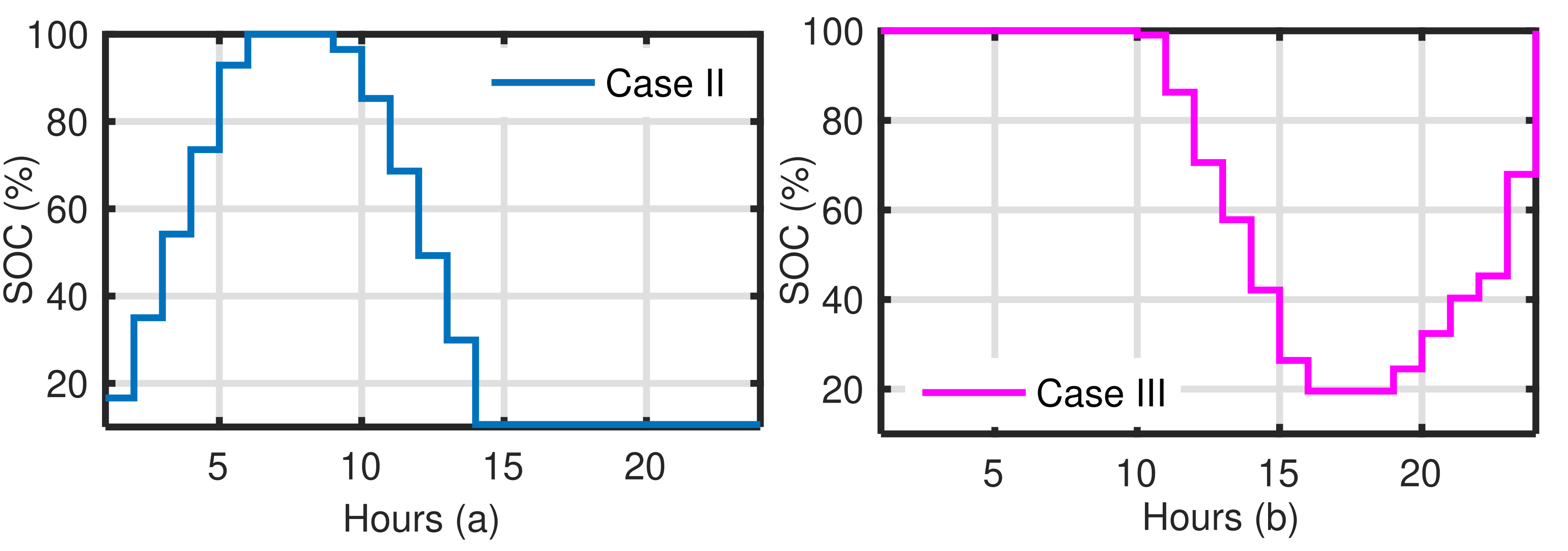
To improve the techno-economic benefits of DNO, the dispatchable DERs have been accommodated with WT in PDN as per the designed two-stage optimization model for the DER mix. In Case II, one BESS has been deployed with WTs as per the proposed strategies. The BESS stores the excess power produced by WTs during the light load hours and dispatch it during the peak load demand when the power generated by WT are not sufficient to meet the load demand. The strategic integration of BESS in Case II has improved the node voltage profile and SDD and reduced the AEL as compare to its base case. However, the reduction in TAEL is low due to the addition of BESS conversion losses with AEL for this case. In Case III, FC is deployed as a dispatchable DER with WTs. This can be seen from Table 5 that Case III outperformed for all the considered parameters in this study system. The FC and its associated BESS are deployed at a common node. Moreover, this can be studied from this case that FC has reduced the WTs penetration as compared to the above case. This is possible due to FC devotion to meet the SDD reduction objective as the SDD is proportionate to the WT penetration. The low BESS conversion losses of FC assisting BESS is due to the small size of BESS. The SOC of BESS for Case II and III are presented in Figure 2.
This can be investigated from Figure 2a that in Case II, BESS charges in low demand hours and discharged in peak demand duration. Figure 2b describes the operation of BESS connected with FC. Here, this BESS is charged and discharged as per the FC operating conditions. Moreover, the results achieved as per Table 5 are further analyzed and endorsed with the help of figures.
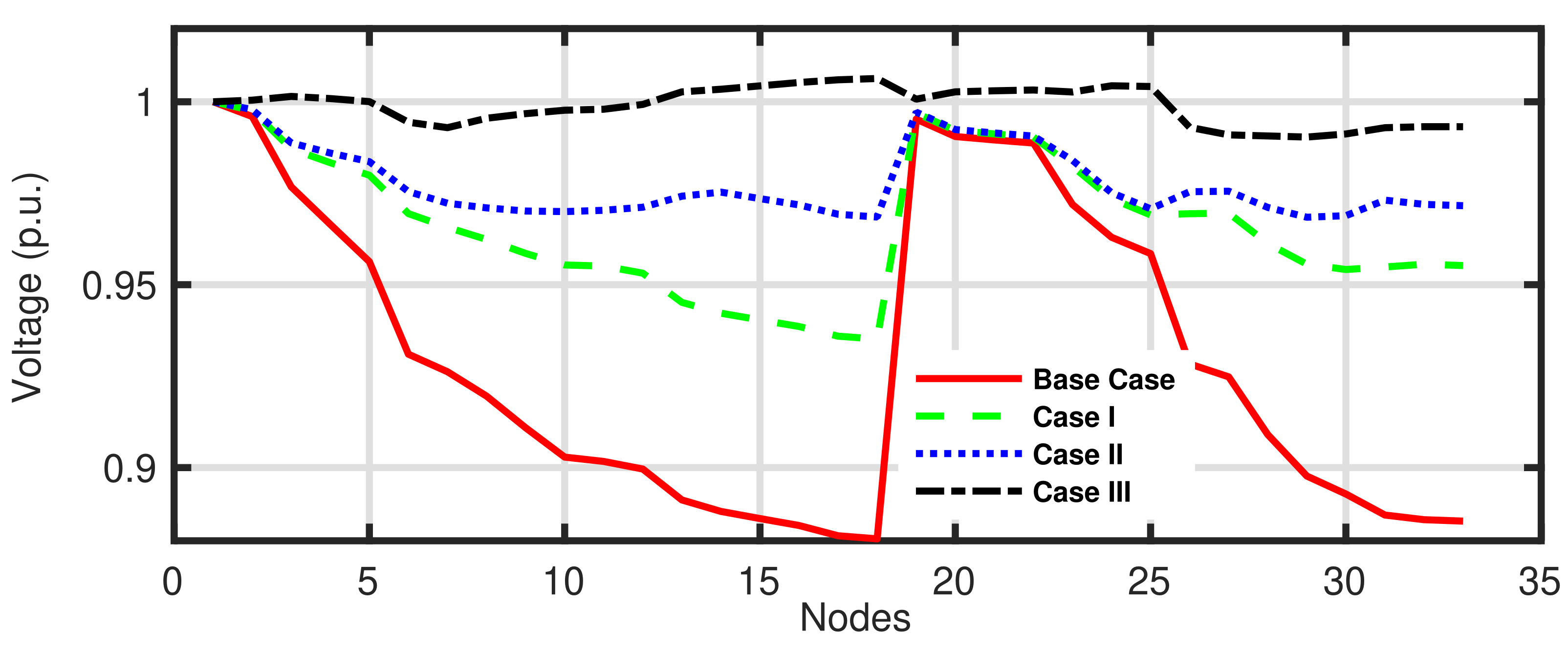
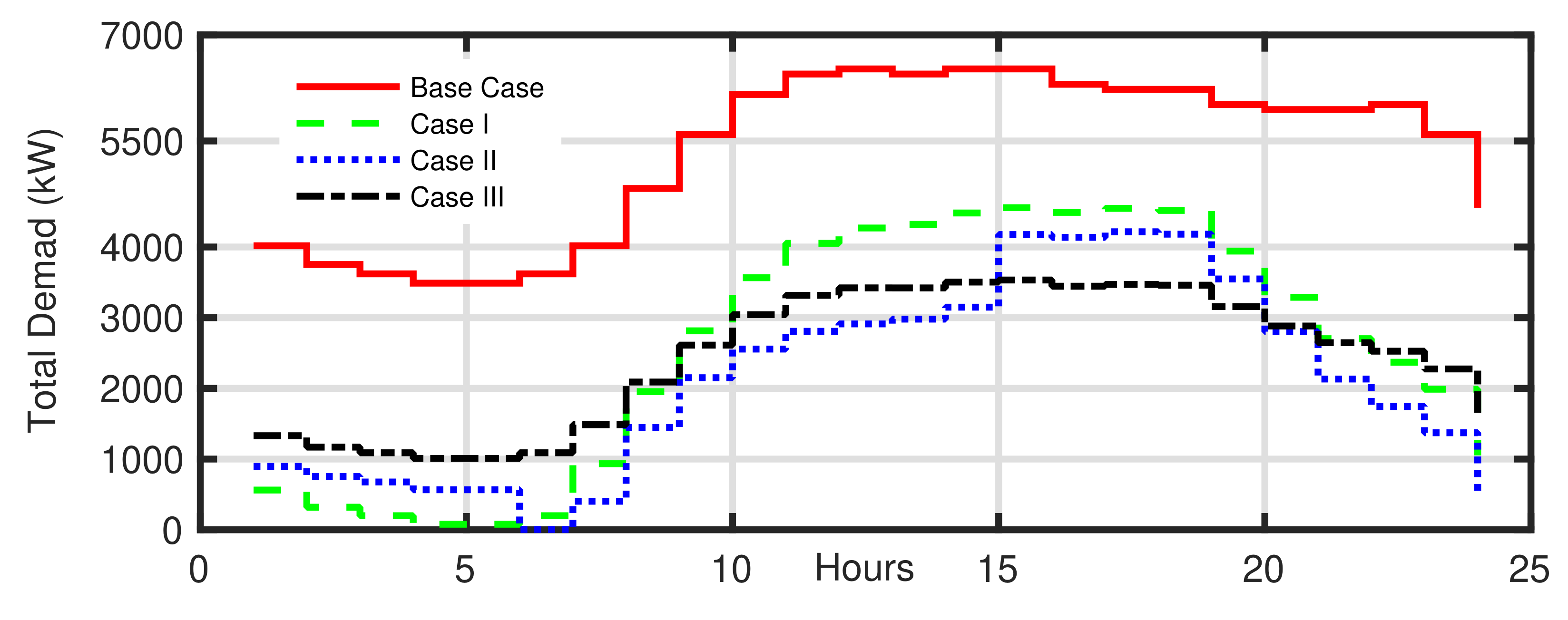
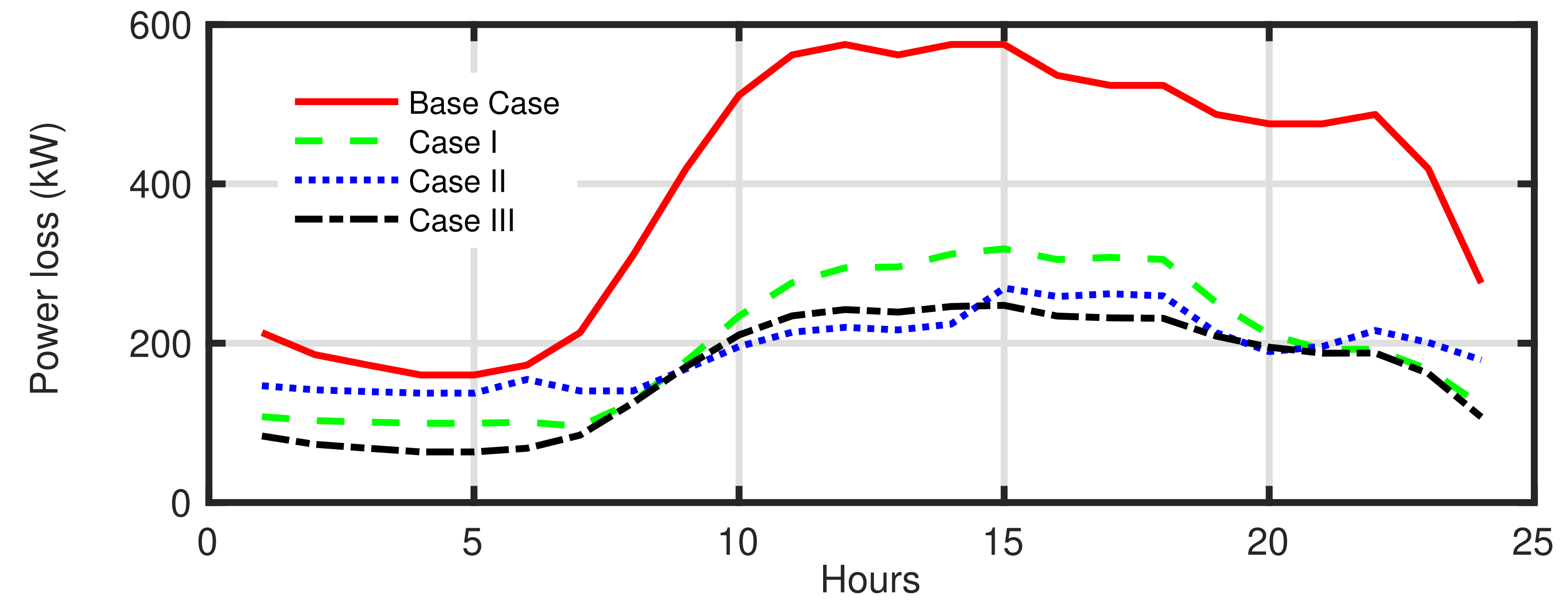
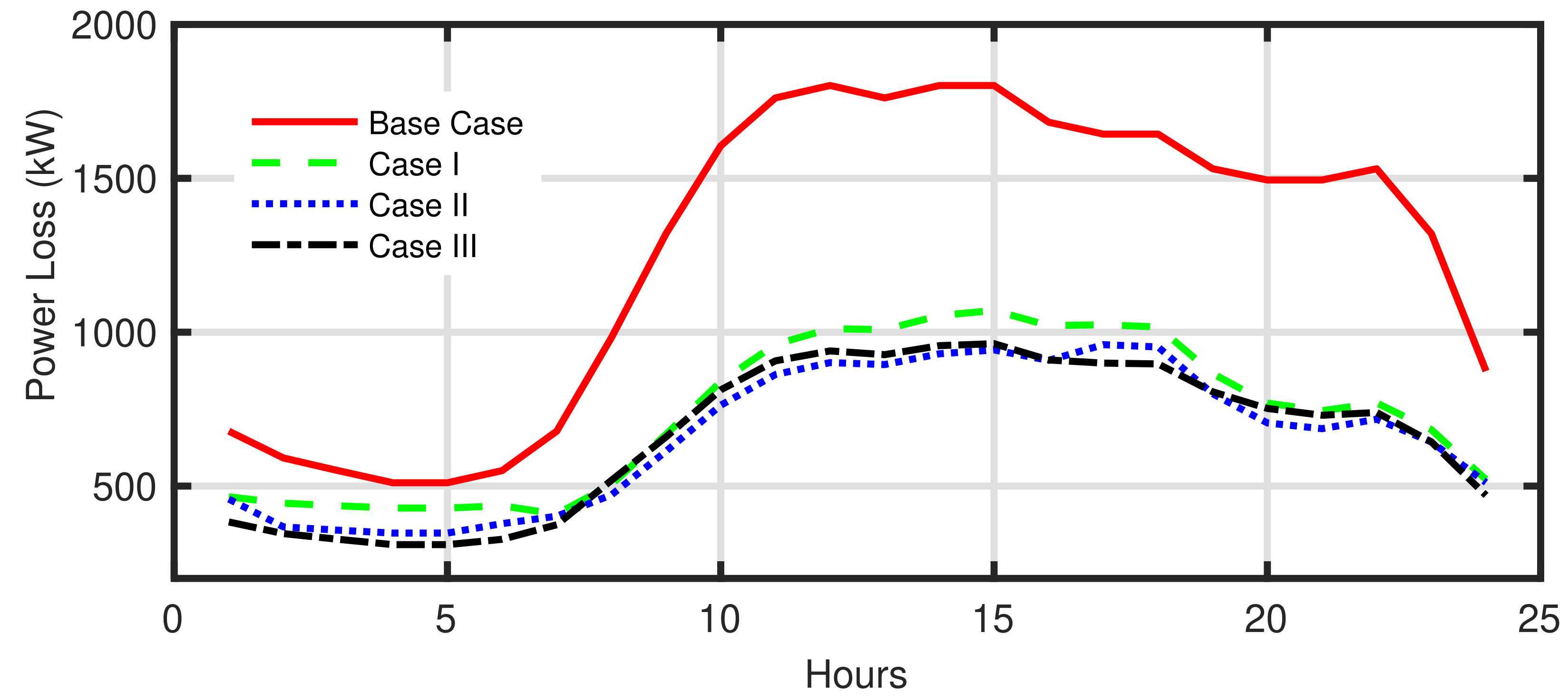
Figure 3 presents the mean node voltage profile of the studied system. It can be observed from these figures that the introduction of DERs, particularly dispatchable DERs have achieved the set objectives. Furthermore, overall best results are observed in Case III. Figure 4 and Figure 5 present the hourly load demand and power loss profile for the studied system, respectively. Figures show that the introduction of dispatchable DERs with WTs have enhanced the performance of PDN as they have helped in peak shaving to DNOs. Further, this can be observed from Figure 4 that BESS and FC have provided a buffer to the sudden change in power generation by the WTs.

4.2.2. DER Mix in 108-Bus Indian Distribution Network

A similar case study is performed on a real-life distribution system with the same parameters. The results obtained are presented in Table 6. It is a large-scale real-life PDN thus has a lower DG penetration as compared to 33-bus test distribution system. Like in Case I of 33-bus test distribution system, an integration of WTs has improved the bus voltages and reduced the AEL with a considerable increase in SDD. Since it is a large-scale practical PDN; therefore, two BESSs are deployed in the network with WTs as per Case II. Furthermore, this case has the highest DERP among all cases due to the excess power requirement of BESSs. The BESSs are deployed at or near the sensitive node of WTs to minimize transmission losses during charging. This presents the working effectiveness of the proposed two-stage model. As per the previous study system, this system reduced AEL and SDD and improved the node voltages. Due to high BESS conversion losses of large size BESSs the case has less reduction in TAEL as compare to all cases. Similar to the previous case, Case III deployed 2 FCs in the studied PDN. Here, deployment of FCs has reduced the AEL and SDD lowest among the studied cases with a considerable enhanced bus voltages. In this system, the FC required a higher capacity of BESSs to achieve all objectives. This results in a slightly lower reduction in TAEL as compare to Case I with the highest reduction in TAEL among all cases.
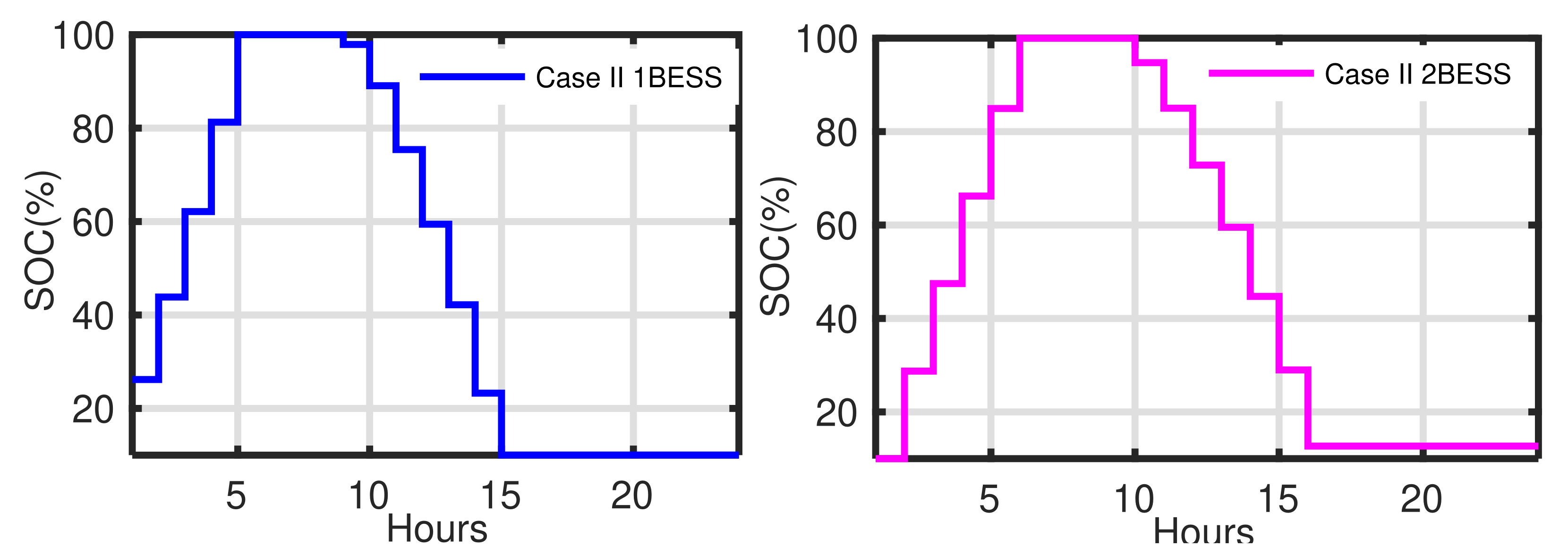
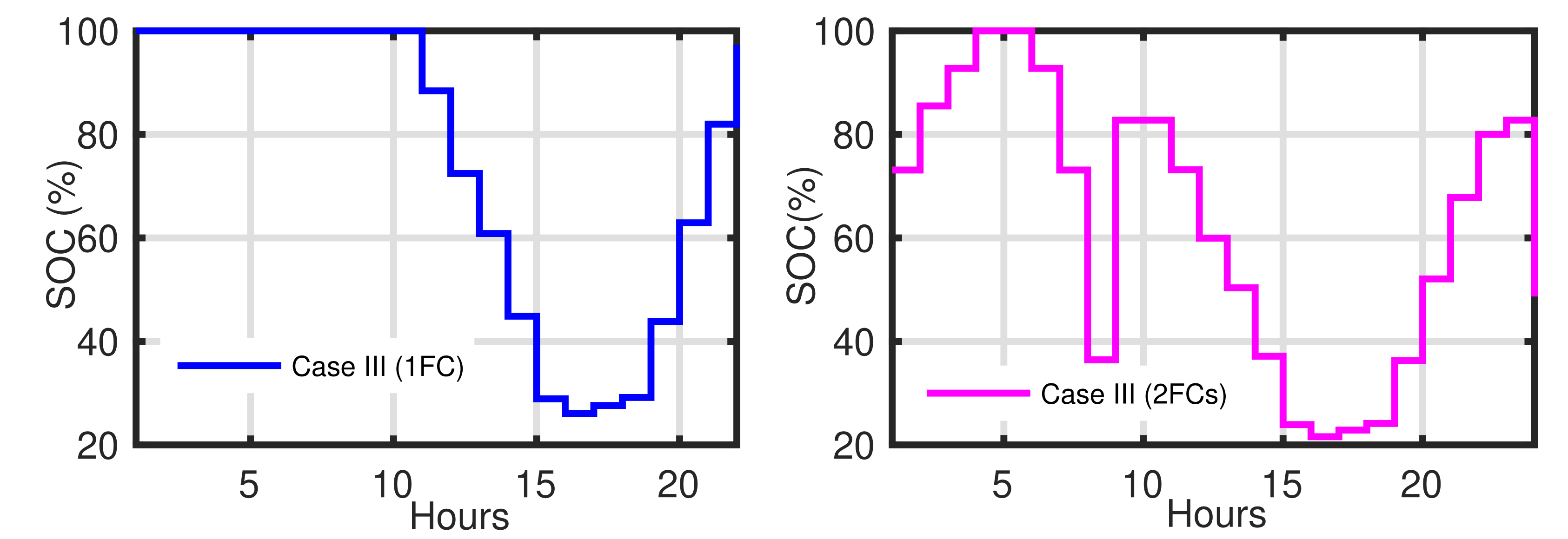
This can be analyzed from Figure 6a,b that both BESS in Case II, charge during the light load hours and are discharged at peak load hours. Figure 7a,b describes the operation of FC connected BESS. Here, as the studied PDN is large and practical so the BESSs are charged and discharged as per the FC operating conditions.
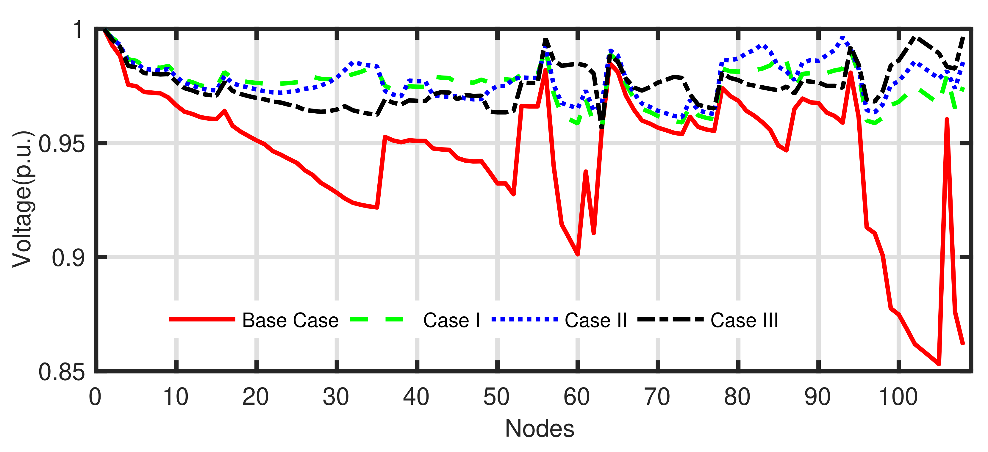
Moreover, the results achieved as per Table 5 are further analyzed and endorsed with the help of figures. Figure 8 shows the mean bus voltages of active distribution network with a mixed integration of DERs. This can be observed from these figures that the introduction of DERs and particularly dispatchable DERs have achieved its set objectives even for a large practical PDN.
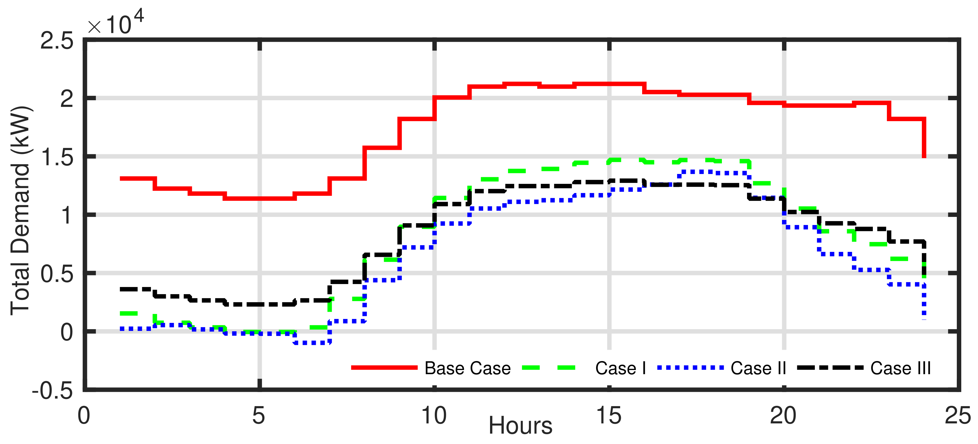
Figure 9 and Figure 10 demonstrate the hourly load demand and power loss profile for this system. It is found from these figures that as similar to medium scale system explained above, the strategic integration of mixed DERs has helped the DNO in peak shaving and cushioning the sudden change in power produced by WTs. After investigating all the cases of two study systems, this can be summarized that the existing PDNs are unable to host the unpredictable penetration of WTs, participial with hour dynamic load demand. Moreover, the dispatchable DERs provide an efficient solution to DNOs to mitigate this effect while simultaneously gaining technical and arbitrage benefits. The studies provide valuable options to choose from considered dispatchable DERs, i.e., BESS and FC, as both have significant benefits. The FC has provided better technical results as compare to BESS, as well as requires a smaller BESS size as compared to the BESS as DER, which is a significant advantage; however, FC is complex and expensive technology.

5. Conclusions

The article proposed a modified variant of standard DA and a sophisticated framework for optimal and strategical integration of mixed and multiple DERs, include a fuel cell and BESS in a renewable distribution network. A multiobjective optimization problem is framed and designed to assist the operators and to meet their day-to-day objectives. A few novels but core objectives are considered with their significant security constraints to strengthen the renewable hosting capability of active distribution networks. Stage-I obtained the optimal sites and sizes of DERs by solving the multiobjective problems aiming to minimize the annual energy loss, bus voltage differences, demand variations, substation back feeds, and power conversion loss of BESS and control variables. Stage-II ensures the optimal dispatch of BESSs to bring their maximum potential. The dispatchable potential of BESS and fuel cells are explored to alleviate the effect of fluctuating wind power. Furthermore, a novel Dragonfly algorithm is introduced with suggested improvements for effectively finding the optimal accommodation of mixed energy resources. The proposed improvements significantly enhanced the global solution searching potential of the standard version of DA regarding worst, mean and best fitness values. The effectiveness of the introduced model and optimization techniques are implemented on benchmark 33-bus and 108-bus Indian city distribution networks for multiple compared test cases. The results obtained are promising and inspirational to achieve the competitive objectives of distribution systems.

Author Contributions

All authors contributed equally to this work. All authors have read and agreed to the published version of the manuscript.

Funding

This research was supported by project “Street2Grid—An electricity blockchain platform for P2P energy trading” (Reference: EP/S001778/2), funded by the Engineering and Physical Sciences Research Council (EPSRC), UK.

Institutional Review Board Statement

Not applicable.

Informed Consent Statement

Not applicable.

Data Availability Statement

Not applicable.

Acknowledgments

The Author, Nand K. Meena would like to acknowledge the funding received from the European Union’s Horizon 2020 research and innovation program under the Marie Sklodowska-Curie grant agreement No. 713694.

Conflicts of Interest

The authors declare no conflict of interest.

References

  1. United Nations Population Fund, Division of Communications and Strategic Partnerships. State of World Population. 2021. Available online: https://www.unfpa.org/ (accessed on 6 September 2021).
  2. Meena, N.K.; Swarnkar, A.; Gupta, N.; Niazi, K.R. Optimal accommodation and management of high renewable penetration in distribution systems. IET J. Eng. 2017, 2017, 1890–1895. [Google Scholar] [CrossRef]
  3. Singh, P.; Meena, N.K.; Slowik, A.; Bishnoi, S.K. Modified African Buffalo Optimization for Strategic Integration of Battery Energy Storage in Distribution Networks. IEEE Access 2020, 8, 14289–14301. [Google Scholar] [CrossRef]
  4. HassanzadehFard, H.; Jalilian, A. Optimal sizing and location of renewable energy based DG units in distribution systems considering load growth. Int. J. Electr. Power Energy Syst. 2018, 101, 356–370. [Google Scholar] [CrossRef]
  5. Singh, P.; Bishnoi, S.K.; Meena, N.K. Moth Search Optimization for Optimal DERs Integration in Conjunction to OLTC Tap Operations in Distribution Systems. IEEE Syst. J. 2019, 14, 880–888. [Google Scholar] [CrossRef] [Green Version]
  6. Awad, A.S.A.; El-Fouly, T.H.M.; Salama, M.M.A. Optimal Distributed Generation Allocation and Load Shedding for Improving Distribution System Reliability. Electr. Power Components Syst. 2014, 42, 576–584. [Google Scholar] [CrossRef]
  7. Moreno-Munoz, A.; De-la Rosa, J.; Lopez-Rodriguez, M.; Flores-Arias, J.; Bellido-Outerino, F.; Ruiz-de Adana, M. Improvement of power quality using distributed generation. Int. J. Electr. Power Energy Syst. 2010, 32, 1069–1076. [Google Scholar] [CrossRef]
  8. Ahmadi, M.; Adewuyi, O.B.; Danish, M.S.S.; Mandal, P.; Yona, A.; Senjyu, T. Optimum coordination of centralized and distributed renewable power generation incorporating battery storage system into the electric distribution network. Int. J. Electr. Power Energy Syst. 2021, 125, 106458. [Google Scholar] [CrossRef]
  9. Theo, W.L.; Lim, J.S.; Ho, W.S.; Hashim, H.; Lee, C.T. Review of distributed generation (DG) system planning and optimisation techniques: Comparison of numerical and mathematical modelling methods. Renew. Sustain. Energy Rev. 2017, 67, 531–573. [Google Scholar] [CrossRef]
  10. Georgilakis, P.S.; Hatziargyriou, N.D. Optimal Distributed Generation Placement in Power Distribution Networks: Models, Methods, and Future Research. IEEE Trans. Power Syst. 2013, 28, 3420–3428. [Google Scholar] [CrossRef]
  11. Borges, C.L.; Falcao, D.M. Optimal distributed generation allocation for reliability, losses, and voltage improvement. Int. J. Electr. Power Energy Syst. 2006, 28, 413–420. [Google Scholar] [CrossRef]
  12. Kumar, A.; Meena, N.K.; Singh, A.R.; Deng, Y.; He, X.; Bansal, R.; Kumar, P. Strategic integration of battery energy storage systems with the provision of distributed ancillary services in active distribution systems. Appl. Energy 2019, 253, 113503. [Google Scholar] [CrossRef]
  13. Radwan, A.A.A.; Mohamed, Y.A.R.I. Grid-connected wind-solar cogeneration using back-to-back voltage-source converters. IEEE Trans. Sustain. Energy 2019, 11, 315–325. [Google Scholar] [CrossRef]
  14. Singh, P.; Meena, N.K.; Yang, J.; Vega-Fuentes, E.; Bishnoi, S.K. Multi-criteria decision making monarch butterfly optimization for optimal distributed energy resources mix in distribution networks. Appl. Energy 2020, 278, 115723. [Google Scholar] [CrossRef]
  15. Yang, Y.; Bremner, S.; Menictas, C.; Kay, M. Battery energy storage system size determination in renewable energy systems: A review. Renew. Sustain. Energy Rev. 2018, 91, 109–125. [Google Scholar] [CrossRef]
  16. Amini, M.; Jalilian, A.; Behbahani, M.R.P. A new method for evaluation of harmonic distortion in reconfiguration of distribution network. Int. Trans. Electr. Energy Syst. 2020, 30, e12370. [Google Scholar] [CrossRef]
  17. Parashar, S.; Swarnkar, A.; Niazi, K.R.; Gupta, N. Modified elephant herding optimisation for economic generation co-ordination of DERs and BESS in grid connected micro-grid. J. Eng. 2017, 2017, 1969–1973. [Google Scholar] [CrossRef]
  18. Thokar, R.A.; Gupta, N.; Niazi, K.; Swarnkar, A.; Meena, N.K. Multiobjective nested optimization framework for simultaneous integration of multiple photovoltaic and battery energy storage systems in distribution networks. J. Energy Storage 2021, 35, 102263. [Google Scholar] [CrossRef]
  19. Jung, J.W.; Keyhani, A. Fuel cell based distributed generation system. In Proceedings of the 2008 12th International Middle-East Power System Conference, Aswan, Egypt, 12–15 March 2008; pp. 610–616. [Google Scholar]
  20. Divya, K.; Østergaard, J. Battery energy storage technology for power systems—An overview. Electr. Power Syst. Res. 2009, 79, 511–520. [Google Scholar] [CrossRef]
  21. Singh, P.; Bishnoi, S. Modified moth-Flame optimization for strategic integration of fuel cell in renewable active distribution network. Electr. Power Syst. Res. 2021, 197, 107323. [Google Scholar] [CrossRef]
  22. Lavorante, M.J.; Sanguinetti, A.R.; Fasoli, H.J.; Aiello, R.M. Equation for General Description of Power Behaviour in Fuel Cells. J. Renew. Energy 2018, 2018, 2678050. [Google Scholar] [CrossRef]
  23. Yeniay, Ö. Penalty function methods for constrained optimization with genetic algorithms. Math. Comput. Appl. 2005, 10, 45–56. [Google Scholar] [CrossRef] [Green Version]
  24. Mirjalili, S. Dragonfly algorithm: A new meta-heuristic optimization technique for solving single-objective, discrete, and multi-objective problems. Neural Comput. Appl. 2016, 27, 1053–1073. [Google Scholar] [CrossRef]
  25. Reynolds, C.W. Flocks, herds and schools: A distributed behavioral model. Comput. Graph. 1987, 2, 4. [Google Scholar]
  26. Eberhart, R.; Kennedy, J. Particle swarm optimization. In Proceedings of the IEEE International Conference on Neural Networks, Perth, Australia, 27 November–1 December 1995; Volume 4, pp. 1942–1948. [Google Scholar]
  27. Wang, G.G. Moth search algorithm: A bio-inspired metaheuristic algorithm for global optimization problems. Memetic Comput. 2018, 10, 151–164. [Google Scholar] [CrossRef]
  28. Singh, P.; Bishnoi, S.; Meena, N.K. Moth Search Optimization for Optimal Integration of DERs for Annual Energy Loss Minimization in Distribution Systems. In Proceedings of the 2018 8th IEEE India International Conference on Power Electronics (IICPE), Jaipur, India, 13–15 December 2018; pp. 1–6. [Google Scholar]
  29. Baran, M.E.; Wu, F.F. Network reconfiguration in distribution systems for loss reduction and load balancing. IEEE Trans. Power Deliv. 1989, 4, 1401–1407. [Google Scholar] [CrossRef]
  30. Meena, N.K. Optimal integration of DERs in coordination with existing VRs in distribution networks. IET Gener. Transm. Distrib. 2018, 12, 2520–2529. [Google Scholar] [CrossRef]
  31. Wang, G.G.; Deb, S.; Coelho, L.D. Elephant Herding Optimization. In Proceedings of the 2015 3rd International Symposium on Computational and Business Intelligence (ISCBI), Bali, Indonesia, 7–9 December 2015; pp. 1–5. [Google Scholar] [CrossRef]
  32. Sultana, S.; Roy, P.K. Multi-objective quasi-oppositional teaching learning based optimization for optimal location of distributed generator in radial distribution systems. Int. J. Electr. Power Energy Syst. 2014, 63, 534–545. [Google Scholar] [CrossRef]
  33. Moradi, M.; Abedini, M. A combination of genetic algorithm and particle swarm optimization for optimal DG location and sizing in distribution systems. Int. J. Electr. Power Energy Syst. 2012, 34, 66–74. [Google Scholar] [CrossRef]
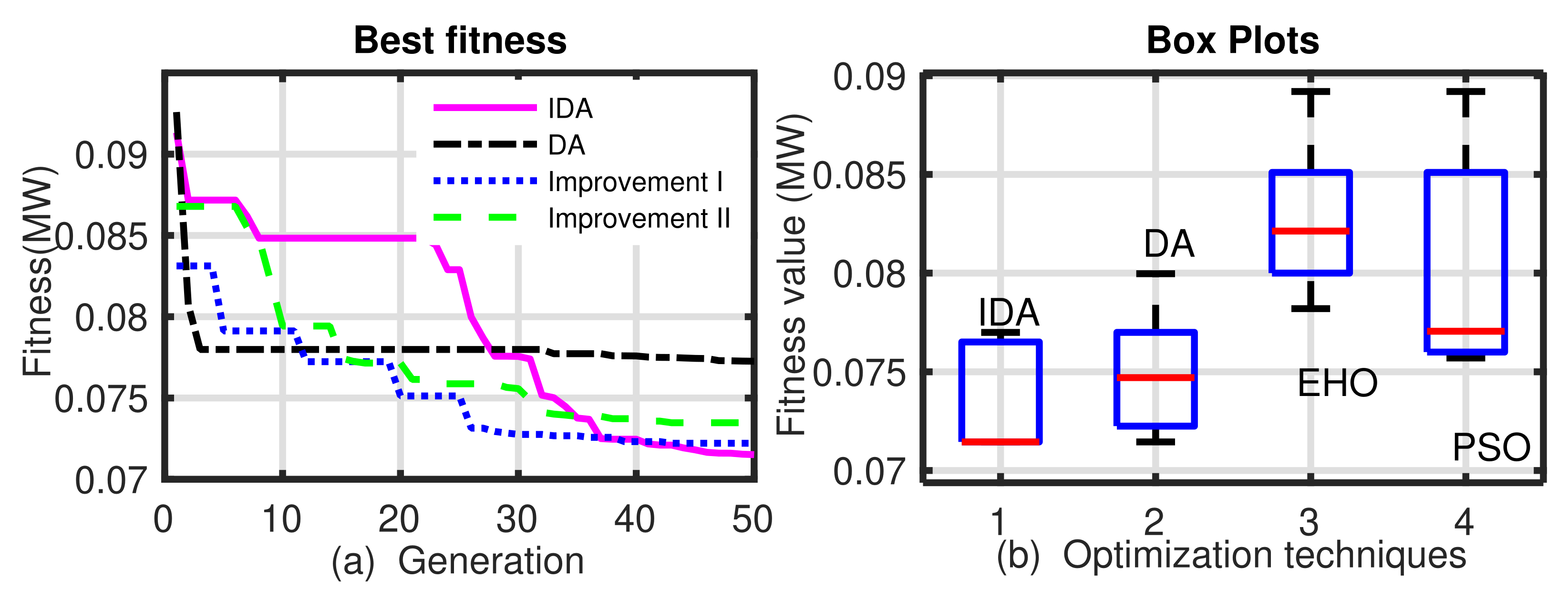
Figure 1. (a) Comparison of convergence characteristics of DA, improvements, and IDA. (b) Box plot of solution archived from IDA, DA, EHO, and PSO for power losses minimization in an ADN.
Energies 14 05690 g001
Figure 2. Hourly SOC (%) of the BESS in (a) Case II, and (b) Case III.
Energies 14 05690 g002
Figure 3. Mean node voltage profiles of 33-bus test distribution system.
Energies 14 05690 g003
Figure 4. Hourly active power demand profile 33-bus test distribution system.
Energies 14 05690 g004
Figure 5. Hourly active power losses 33-bus test distribution system.
Energies 14 05690 g005
Figure 6. Hourly (%) of SOC for (a) I BESS, and (b) II BESS for Case II.
Energies 14 05690 g006
Figure 7. Hourly (%) of SOC for (a) I BESS of FC, and (b) II BESS of FC for Case III.
Energies 14 05690 g007
Figure 8. Mean node voltage profiles of 108-bus Indian distribution network.
Energies 14 05690 g008
Figure 9. Hourly active power demand of 108-bus Indian distribution network.
Energies 14 05690 g009
Figure 10. Hourly active power loss of 108-bus Indian distribution network.
Energies 14 05690 g010
Table 1. Case study parameters.
Parameter and SpecificationValue
ζ  ,  , T L v l  , P d g m a x  365, 90, 24, 2500 (kW)
ν c _ o u t , ν ( r ) , ν c _ i n 20, 15, 4 (m/s)
S O C m a x , S O C m i n 100, 10 (%)
P c m a x , P d m a x 1000 (MW) each
B s m a x 50% of FC capacity & 6000 (kWh)
Table 2. DA and IDA results comparison.
TechniqueBest *Mean *Worst *  SD
DA0.07210.07410.07930.00252
IDA0.07150.07300.07690.00239
* values in MW.
Table 3. Simulations results of single objective optimization problem for power loss minimization.
TechniquesOptimal DG [Sizes in MW] SizePower Loss in MW
TLBO [32][1.183]12; [1.191]28; [1.186]300.1246
GA [33][1.500]11; [0.423]29; [1.071]300.1063
PSO [33][1.177]08; [0.982]13; [0.830]320.1053
GA/PSO [33][0.925]11; [0.863]16; [1.200]320.1034
QOTLBO [32][1.083]13; [1.187]26; [1.199]300.1034
CMSO [5][0.756]14; [1.097]24; [1.066]300.0714
IDA[0.754]15; [1.100]24; [1.072]310.0714
Table 4. Number of DERs to be optimal accommodation.
Case33-Bus Distribution Network108-Bus Indian Distribution Network
Base CaseNO DERsNO DERs
Case I3 WTs7 WTs
Case II3 WTs & 1 BESSs7 WTs & 2 BESSs
Case III2 WTs & 1 FCs5 WTs & 2 FCs
Table 5. Optimal sites and sizes of mixed DERs in 33-bus test distribution system obtained by IDA two-stage optimization method.
CasesDER Sites [Sizes (kW)]DERP (%)BESS Sites [Sizes (kWh)]SDD (kW)AEL (MWh)Min./Mean Voltage (p.u.)Conv. Loss (MWh)Reduc. in TAEL (%)
Base---1165.213493.270.899/0.940--
Case I. (EHO) 07 [ 500 ] W T 10 [ 1250 ] W T 32 [ 2000 ] W T 47.67-1785.91821.00.956/0.975-47.67
Case I. (PSO) 04 [ 500 ] W T 11 [ 1500 ] W T 31 [ 2000 ] W T 67.29-1835.91782.70.956/0.975-48.96
Case I. (IDA) 11 [ 850 ] W T 27 [ 1250 ] W T 32 [ 1250 ] W T 56.36-1734.21750.50.935/0.966-50.04
Case II. (IDA) 14 [ 1500 ] W T 27 [ 500 ] W T 31 [ 2000 ] W T 67.2910[5170]1386.41685.70.967/0.978357.241.54
Case III. (IDA) 27 [ 1876 ] F C 11 [ 850 ] W T 25 [ 500 ] W T 54.28874.60967.91447.50.989/0.998245.551.53
Note: bold results represents the best solutions.
Table 6. Optimal sites and sizes of mixed DERs in 108-bus Indian distribution system obtained by IDA two-stage optimization method.
CasesDER Sites [Sizes (kW)]DERP (%)BESS Sites [Sizes (kWh)]SDD (kW)AEL (MWh)Min./Mean Volt. (p.u.)Conv. Loss (MWh)Reduc. in TAEL (%)
Base---3780.610,996.910.876/0.95--
Case I. 27 [ 2250 ] W T
34 [ 1250 ] W T
42 [ 1500 ] W T
48 [ 850 ] W T
60 [ 2000 ] W T
85 [ 1500 ] W T
102 [ 2000 ] W T
22.11-5712.26417.40.956/0.975-41.64
Case II. 26 [ 1500 ] W T
32 [ 2250 ] W T
39 [ 1500 ] W T
60 [ 2250 ] W T
63 [ 1500 ] W T
93 [ 2250 ] W T
102 [ 2250 ] W T
23.3992[4756.9] 102[5337.3]5233.558100.961/0.9781802.530.78
Case III. 60 [ 2671.9 ] F C
102 [ 1841.9 ] F C
31 [ 1500 ] W T
43 [ 1250 ] W T
46 [ 1500 ] W T
72 [ 500 ] W T
86 [ 1500 ] W T
20.98633.24; 800.14082.25806.40.956/0.9751070.637.46
Note: bold results represents the best case solutions.
Publisher’s Note: MDPI stays neutral with regard to jurisdictional claims in published maps and institutional affiliations.