Abstract
This paper focuses on the loss estimation for the multiphase induction machine (IM) operating under fault-tolerant conditions through the field–circuit coupling finite element method (FEM). Both one-phase and two-phase open-circuit faults of a seven-phase IM are researched, and different spatial positions of the fault phases are taken into consideration. The magnitudes and phase angles of the residual phase’s current are deduced based on the principle of equal magnitude of the residual phase currents and unchanged fundamental magnetic motive force (MMF). The magnetic fields’ coupling between the fundamental and harmonic planes is analyzed. Then, the time-stepping electromagnetic fields calculation of the seven-phase IM are carried out under the commercial software Simplorer–Maxwell environment. The transient and steady performance for both the health and fault conditions are obtained based on the rotor field-oriented control (RFOC) strategy. The Joule loss and iron loss are calculated for the torque step and slope responses. The seven-phase motor driving platform is established to verify the numerical calculation results. The proposed method is effective for predicting the loss and designing a reasonable operating range for multiphase IM operating under fault-tolerant conditions considering the thermal balance.
1. Introduction
Multiphase induction machines show remarkable advantages in industrial applications of high-power, high-reliability and high-torque density, such as vessel electric propulsion, more electric aircrafts, locomotive traction and electric vehicles [,]. The inherent features of power splitting, better fault tolerance and additional degrees of control freedom cause the upward research in multiphase IM. Abundant efforts have been devoted in areas of designing, modelling and driving the multiphase machine for several decades. Recent research supports the future widespread application of multiphase machines [,,,,]. There has been considerable research undertaken on control strategies [,,,,,,] and fault detections [,,] for open-circuit faults; however, there are few studies on loss and efficiency issues under fault-tolerant conditions.
The closed loop control for the phase currents is essential under fault-tolerant conditions due to the asymmetrical nature of the electrical and magnetic structure, so that the field–circuit coupling FEM is adopted to complete the investigation. The field–circuit coupling FEM has been successfully employed to solve the motor issues [,,,,]. The code for field–circuit coupling finite element (FE) calculation is presented to calculate the transient performance of a single-phase IM, and the results are compared with the commercial software FLUX in literature []. The FEM with external circuit coupling has been used to estimate the stray loss [].
This paper focuses on the loss calculation and estimation for the multi-phase IM operating under open circuit fault-tolerant conditions. The numerical and experimental works are both carried out to assess the iron loss, rotor Joule loss and total loss. The residual phase currents for various open-circuit fault conditions are deduced based on the principles of unchanged fundamental magnetic motive force (MMF) and the equal amplitudes of residual phase currents. The step and slope responses of torque are performed using field-circuit FEM under both health and fault-tolerant conditions using a seven-phase IM in this paper. The iron loss is calculated based on the classical iron model, and the time-harmonics caused by the inverter are taken into consideration [,,,,]. The stator and rotor Joule loss are calculated through the RMS of the stator and rotor currents. The spatial vectors of MMF caused by the coupling between the fundamental and harmonic planes are analyzed to illustrate the increasing rotor Joule loss. The total increased loss and efficiencies under the fault-tolerant conditions obtained by the numerical method are compared with the experimental results. The reasonable operation range for load torque is provided for the seven-phase IM under different fault-tolerant conditions considering thermal balance.
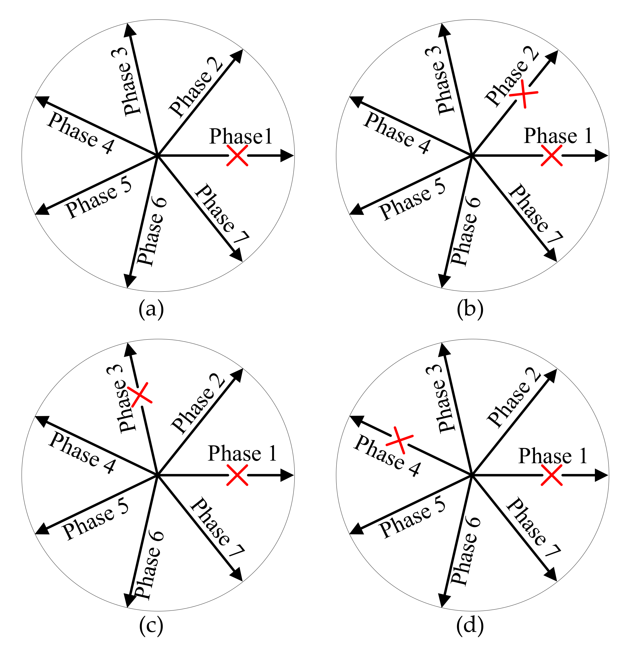
2. Fault-Tolerant Current Design and Analysis
2.1. Residual Phase Currents Reconstitution
Unlike the common three-phase machines, the smooth and steady torque can also be obtained for the multiphase machines under open-circuit fault conditions. The principle for the reconstitution of residual phase currents is keeping the MMF of fundamental plane consistent with the health condition, so that the smooth electromagnetic torque can be expected on the fundamental plane. Both one-phase and two-phase open-circuit faults conditions for a seven-phase IM are discussed in this section. Several relative spatial positions for the fault phases are taken into account, which are described in Figure 1.
Figure 1.
Spatial position of fault phases. (a) Fault 1: 1st phase fault; (b) Fault 2: 1st and 2nd phase fault; (c) Fault 3: 1st and 3rd phase fault; (d) Fault 4: 1st and 4th phase fault.
Firstly, the seven-phase phase currents can be given as Equation (1).
where , are seven phase currents, , are the amplitudes of phase currents and is the angular frequency.
The constraint for the circular magneto motive force (MMF) can be expressed as Equation (2).
where .
The coordinate components of the MMF can be obtained by simplifying Equation (2), which can be described as Equation (3). Equation (3) can be used as one of the constraints when reconstructing the fault-tolerant currents.
For the circumstance of no neutral line, another constraint for the residual phase currents should be given as Equation (4) [].
The constraint of constant amplitudes of the residual phase currents is employed in this paper, which can be given as Equation (5).
The magnitudes and phase positions of the residual phase currents can be deduced based on Equations (1)–(5), and the optimized results are shown per-unit in Table 1, from which it can be seen that the phase positions become unsymmetrical under fault-tolerant conditions and the amplitudes of residual phase currents were kept consistent.
Table 1.
Residual phase currents reconstruction.
2.2. Coupling between the Fundamental and Harmonic Planes
The health condition is symmetrical for both the spatial and electric quantities, so that the relationship for the fundamental and harmonic planes are independent from each other. However, the fundamental and harmonic planes are coupled with each other under fault conditions due to the asymmetrical fault-tolerant currents. The asynchronous rotational MMF will be produced by the interaction between the asymmetrical fundamental currents and the spatial winding harmonics. The seven-phase synthetic magnetomotive force can be expressed as Equation (6).
where is the order of the spatial harmonics; is the phase number and is from Table 1; is the spatial electric angle; is magnitude of winding function; and is the number of series turns per phase.
The coupled harmonic MMF components for the 3rd and 5th harmonic planes are listed in the first column of Table 2, and the magnitudes are listed in the other columns. The speeds of the harmonic magnetic fields are one third and one fifth of the fundamental magnetic field with forward and reverse direction.
Table 2.
Principle of equal magnitude of the residual phase currents.
3. Time-Stepping FE Calculation
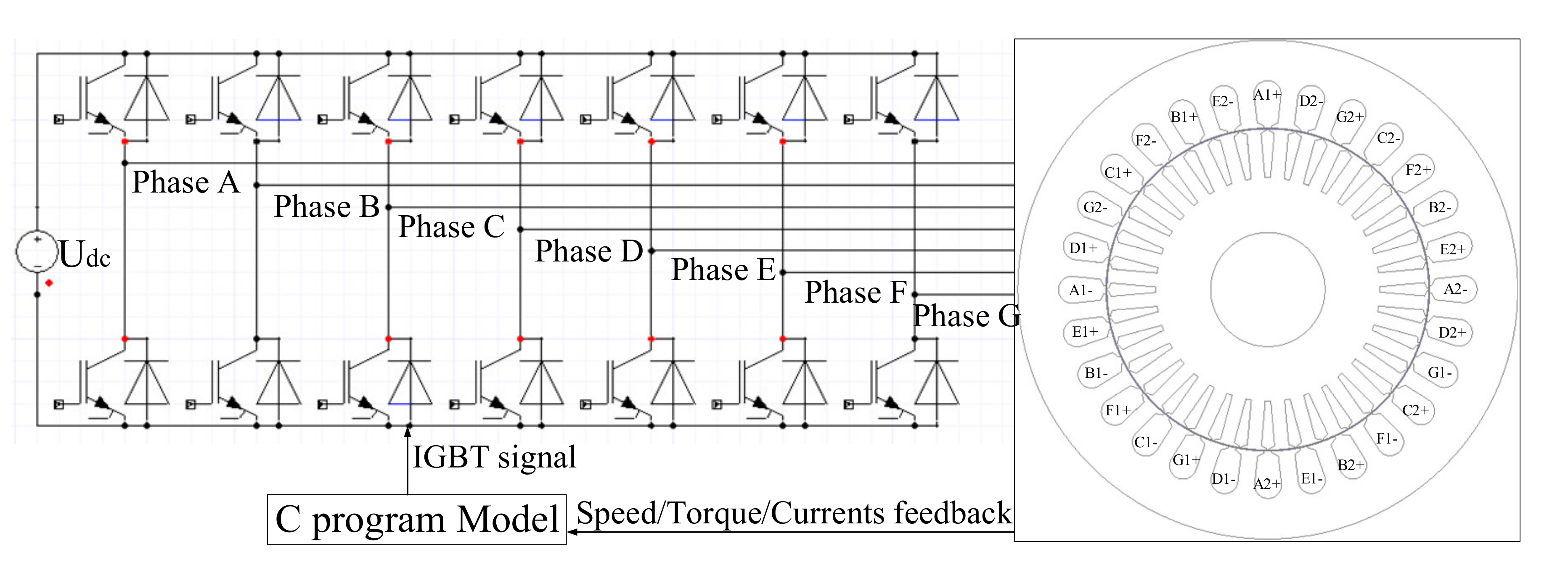
3.1. Field–Circuit Coupling FE Model
The field–circuit coupling FEM model is shown in Figure 2, which is composed of the seven-phase half-bridge inverter and a seven-phase IM. A redesigned seven-phase IM with concentrated windings is used as prototype for the finite element calculation and the subsequent experimental validation. The specifications of the seven-phase IM are listed in Table 3. The fault-tolerant operation for the prototype is carried out based on the RFOC strategy using a C program model. The block diagram of the C program model is drawn in Figure 3. The traditional mode of supplying voltage source is infeasible under fault-tolerant conditions due to the asymmetrical of residual phase currents, so that the current closed-loop control strategy is adopted in this simulation.
Figure 2.
Field−circuit coupling FE model.
Table 3.
Main parameters of the prototype.
Figure 3.
Block diagram of the C program model.
The common dual close-loop control is employed in this scheme, where hysteresis controller is adopted in the current loop and traditional PI controller is used in the speed loop. The constant magnetizing current is used as the d-axis reference current, and the q-axis reference current is the output of the speed loop. The q-axis reference current is calculated based on the electromagnetic torque equation, which is given by Equation (7).
where is electromagnetic torque, is pole pairs, is magnetizing inductance, is rotor self- inductance, is d-axis stator current and is q-axis stator current.
The reference fault-tolerant phase currents are calculated based on Table 1, and then the IGBT signals are obtained using reference and feedback currents through the hysteresis current controller.
The proportional-integral controller is adopted in the speed loop, and the hysteresis controller is adopted in the current loop for tracking the reconstructed phase currents. The rated speed and rated torque of the prototype motor are 1460 rpm and 30 Nm. The transient equation, field–circuit coupling equation and the mechanical equation are described as Equations (8)–(10).
Where , , and are, respectively, the magnetic permeability, component of magnetic vector potential, stator current density and rotor bar conductivity.
where , , , and are, respectively, stator flux, stator end leakage inductance, stator terminal voltage, stator phase current and resistance of stator winding.
where , , , and are, respectively, the moment of inertia, damping coefficient, electromagnetic torque, load torque and mechanical angular velocity.
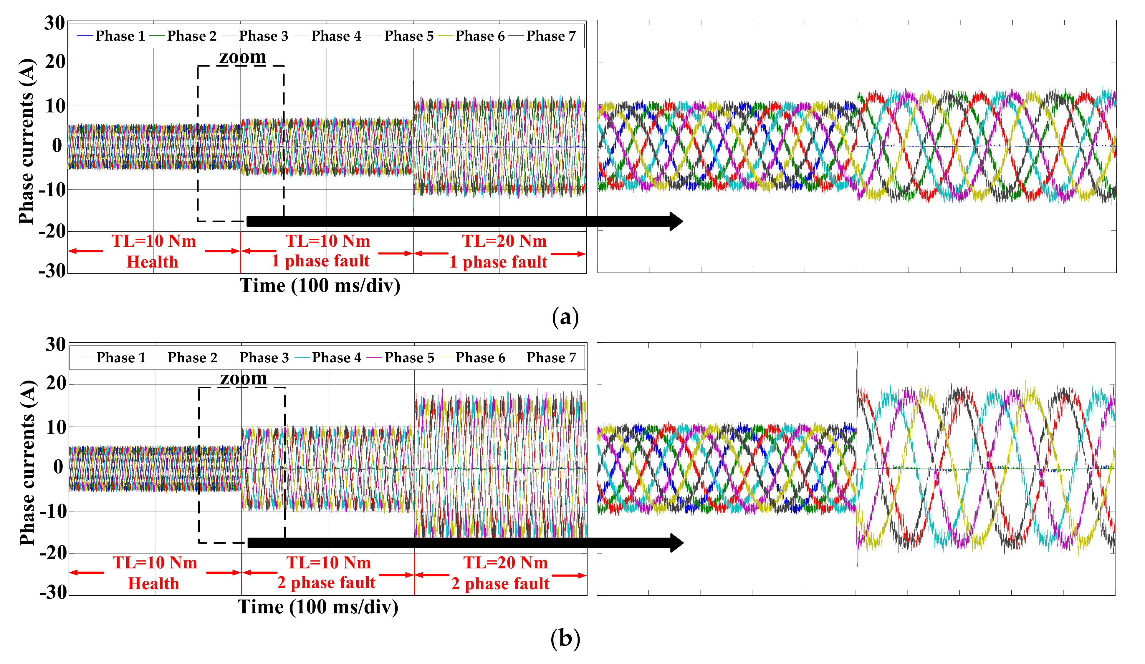
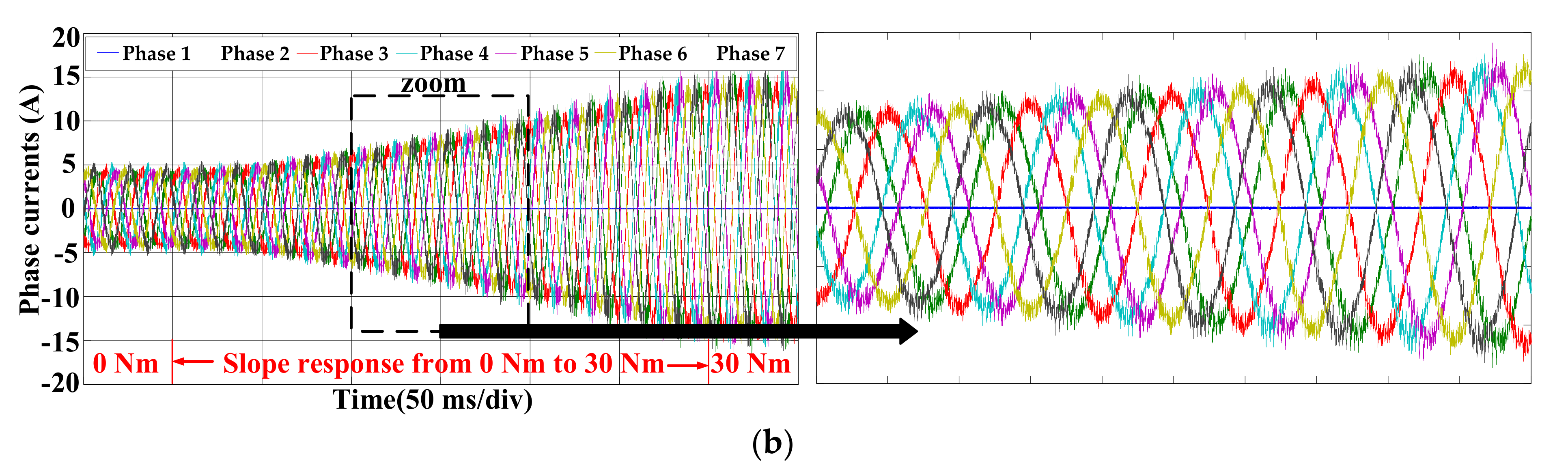
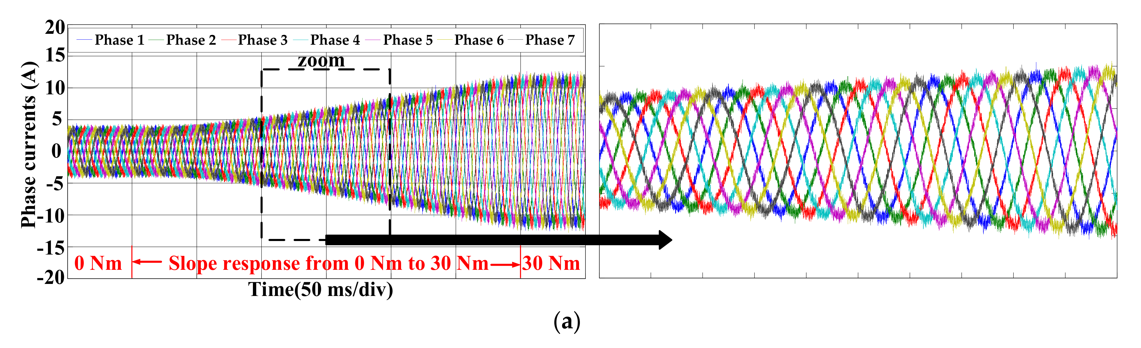
3.2. Transient and Steady Performance
The simulated results of the field–circuit coupling FEM are presented in this section. Both the step and slope responses for the load torque are performed for the seven-phase IM under health and fault-tolerant circumstances. For the load step process, the seven-phase IM is firstly operated under the rated speed, while the load torque for the step response is from 10 Nm to 20 Nm. For the slope response process, the load torque is increased from 0 Nm to 30 Nm gradually.
The performance for the stator phase currents under the torque step response and slope response are shown in Figure 4 and Figure 5, respectively, where the corresponding load conditions are noted. The transient processes from the health condition to the fault conditions are depicted in the zoom areas of Figure 4. The currents for the fault phases were restricted to zero when the machine went into the fault-tolerant condition, and the amplitudes of the residual phase currents increased for the fault-tolerant condition compared with the health condition. The current waveforms for the gradually increasing torque process under both the health and fault conditions are amplified in the zoom areas of Figure 5.
Figure 4.
Currents performance for torque step response. (a) 1 phase fault (fault 1); (b) 2 phases fault (fault 2).

Figure 5.
Current performance for the torque slope response. (a) Health condition; (b) 1 phase fault condition.
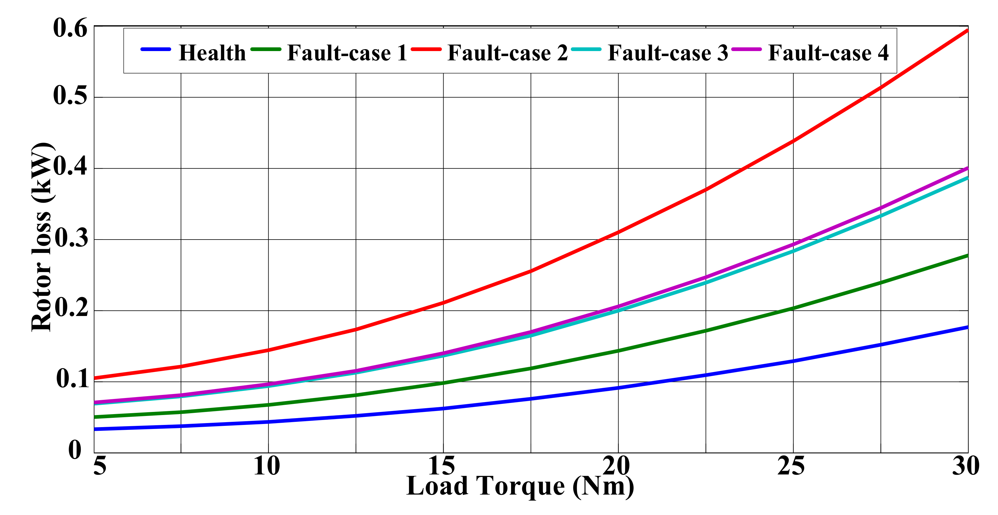
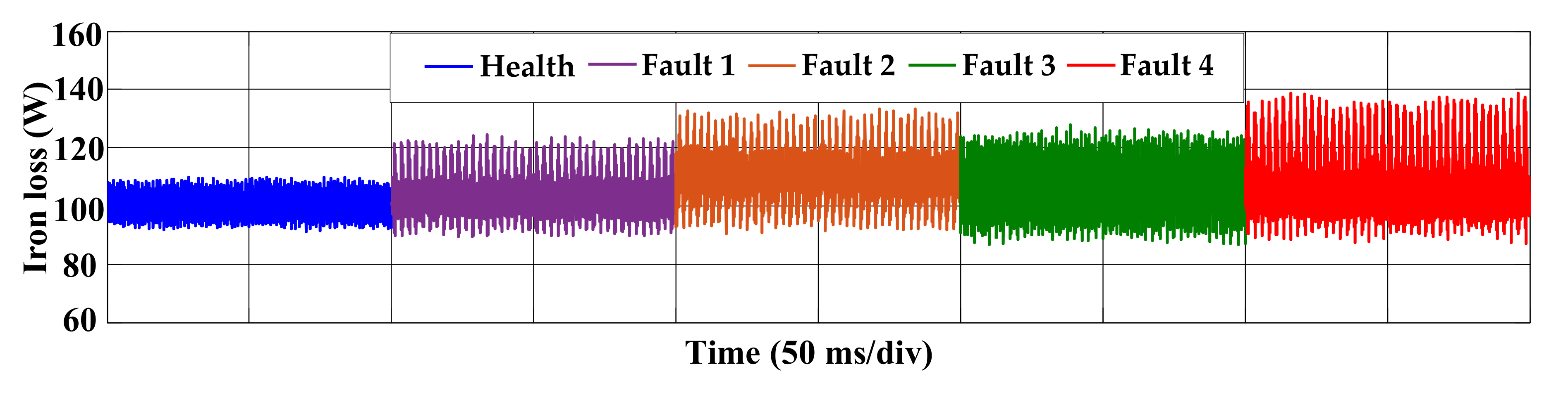
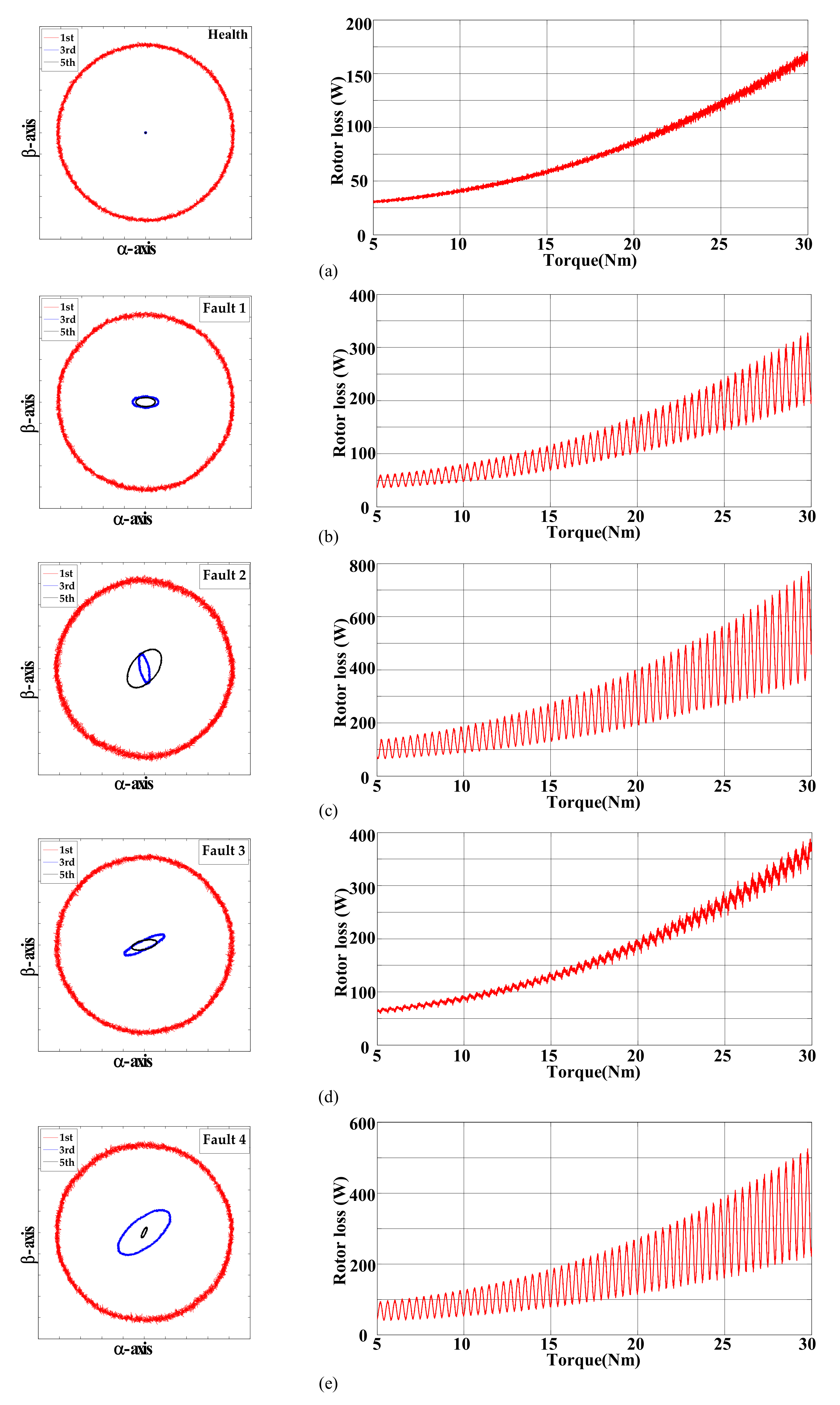
3.3. Loss Calculation and Analysis
The loss will increase due to the machine operating under the fault-tolerant condition due to the increased rms currents and the additional harmonic MMF. The derating operation should be considered to limit the loss and temperature rise. The calculations of loss under fault conditions are of great concern. The total losses of induction machine include the iron loss, stator copper loss, rotor Joule loss and stray loss, of which the iron and rotor Joule loss are calculated in detail in this section. As the stator current is closed-loop-controlled, the increased stator copper loss can be obtained through Table 1. The stray loss is deemed as 2% of the output power. The classic iron loss model is used in this paper, which can be given as Equation (11).
where , and are the hysteresis loss coefficient, classic eddy-current loss coefficient and excess loss coefficient, which are obtained based on the iron loss curves from manufacturer. is the power supply frequency and is the amplitude of the flux density.
The FE calculation results of the iron loss and rotor Joule loss for both the health and fault-tolerant conditions with 20 Nm load torque are shown in Figure 6 and Figure 7. Both the iron loss and rotor Joule loss are increased for the fault conditions compared with the health condition. The iron losses increase slightly because the amplitudes of fundamental magnetic field are kept unchanged. In addition, the frequencies for the harmonic magnetic fields are relatively low, which are one third or one fifth of the fundamental one, while the rotor Joule loss increases remarkably due to the asynchronous harmonic magnetic fields with elliptic trajectories. Furthermore, the rotor Joule loss is oscillating with the time variance, due to the fact that the periodic harmonic loss is superposed on the fundamental loss.
Figure 6.
FE results of the iron loss for health and fault conditions under 20 Nm.
Figure 7.
FE results of the rotor Joule loss for health and fault conditions under 20 Nm.
The actual values and per-unit values for the rotor Joule loss under 20 Nm load, where the basic value is the loss under health condition, are presented in Table 4. The rotor Joule loss for torque slope response is calculated, and the numerical results for health and fault conditions are shown in the right part of Figure 8, from which the rotor Joule loss curves varying with load torque can be obtained. The pulsating for the rotor Joule loss become larger as the torque increases. The trajectories of the MMF spatial vectors for both the fundamental and harmonic planes are drawn in the left part of Figure 8 to further illustrate the increasing loss. The MMF vector trajectories of the fundamental plane are unit circles for the health and each fault-tolerant condition, which can satisfy the principle of the unchanged fundamental MMF. There exists no harmonic MMFs for the health condition, while the MMF vector trajectories of the harmonic planes are ellipses under fault conditions, which is caused by the reconstructed stator currents mapping on the spatial harmonic planes. In addition, the increased iron loss and rotor Joule loss under fault-tolerant conditions caused by the harmonic MMF can be deemed as stray loss. The rotor Joule loss and total loss deteriorate most seriously for the fault-tolerant condition of two adjacent phases open-circuit. The rotor Joule loss obtained by FEM for both the fault-tolerant conditions and health condition with regard to the torque slope response are shown by solid lines in Figure 9. The distinct loss is caused by the different fault conditions, which induce various spatial MMFs.
Table 4.
Loss distribution for fault conditions under 20 Nm load.
Figure 8.
Trajectories of spatial MMF vectors for fundamental and harmonic planes. (a) Health, (b) Fault 1, (c) Fault 2, (d) Fault 3 and (e) Fault 4.
Figure 9.
Calculated rotor Joule loss varying with torque.
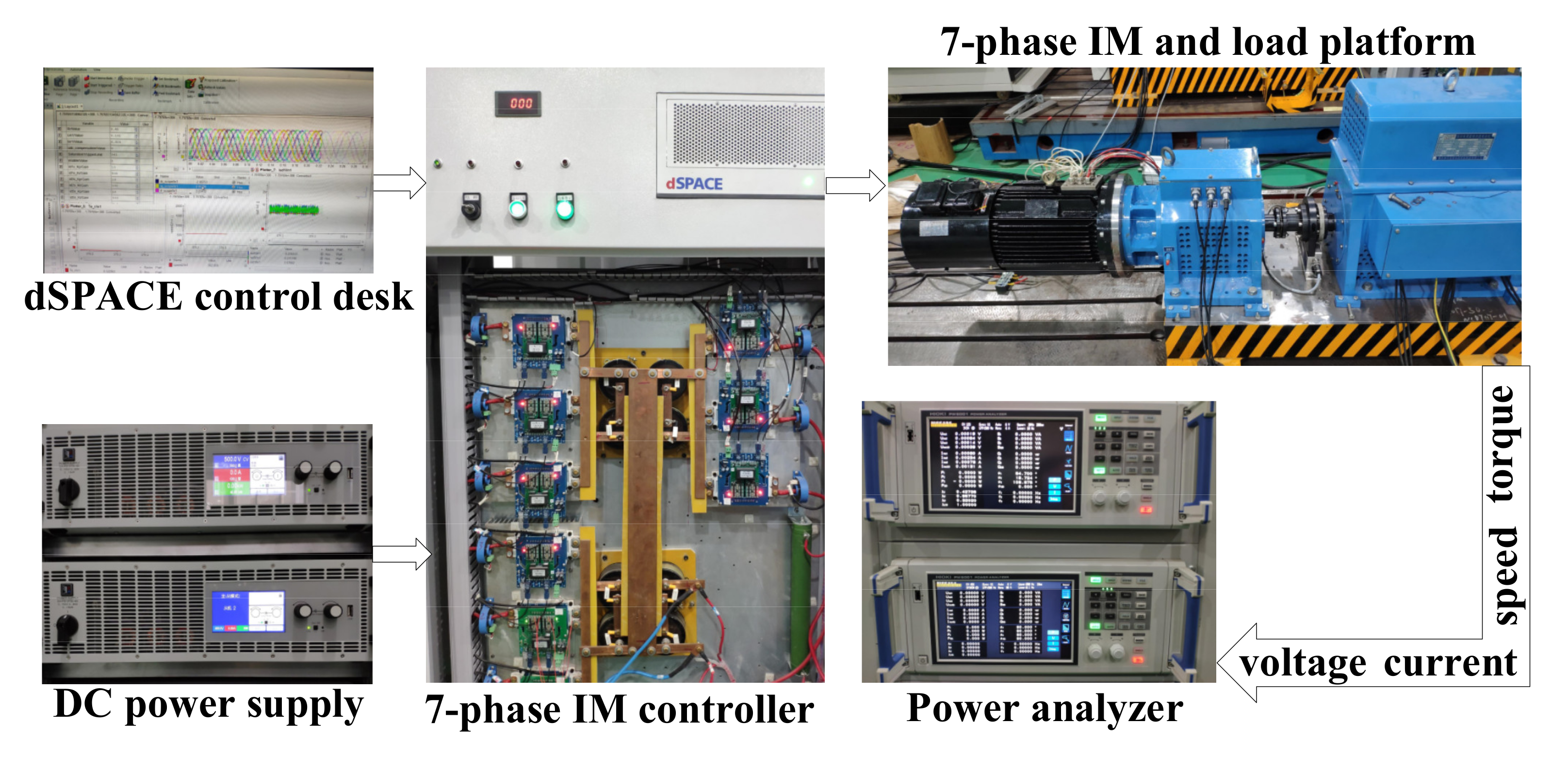
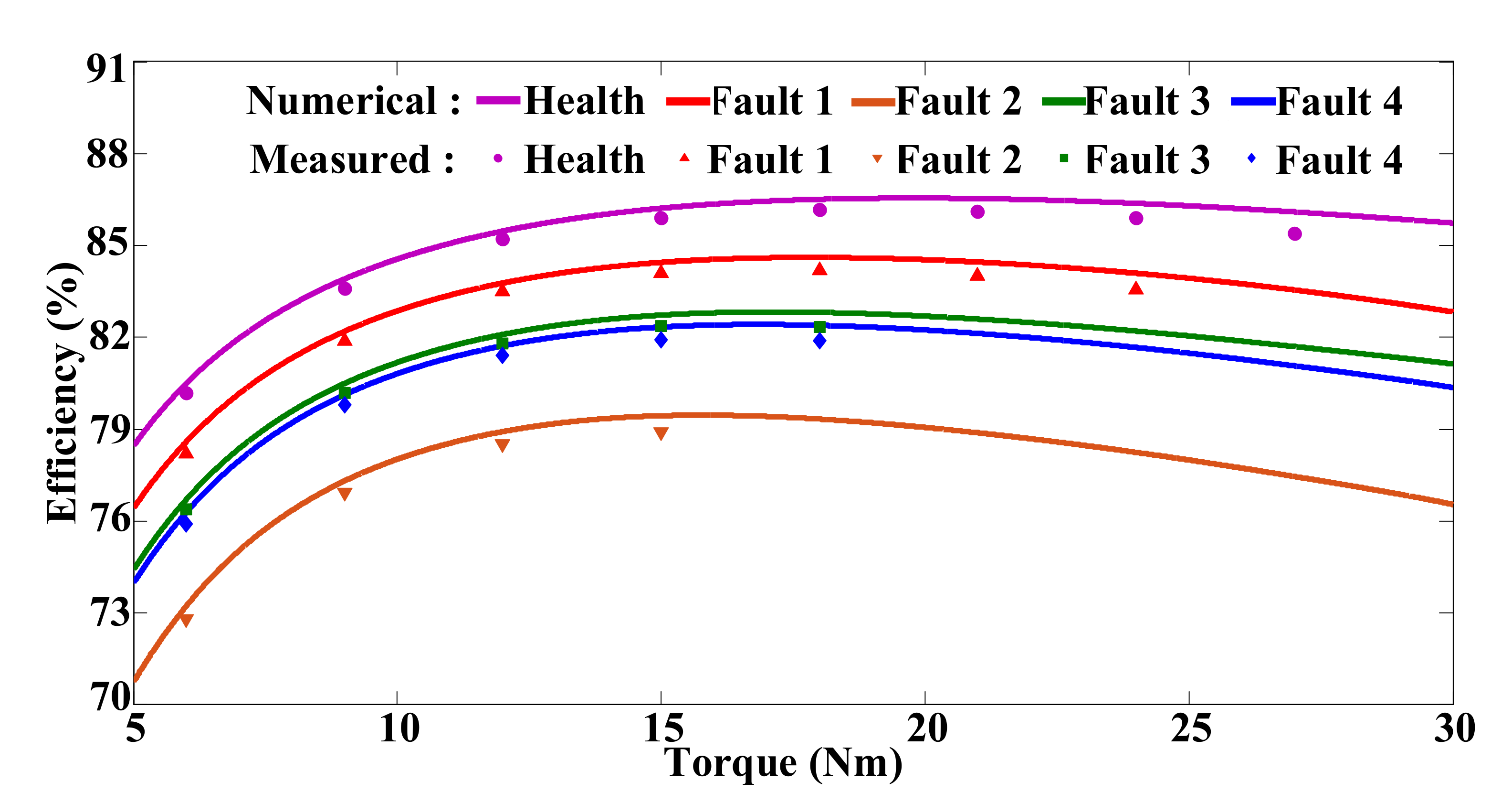
4. Experimental Validation and Analysis
The seven-phase IM driving system is depicted in Figure 10, which is composed of a seven-phase IM with concentrated windings, torque sensor, dSPACE controller, multiphase inverter, DC power supply and the alternating current servo load. A power analyzer with 12 channels is used to complete the efficiency test. The multiphase inverter is composed of the IGBT power module, and the nine-phase half-bridge modules share the common bus voltage. The control signals from the dSPACE controller are transferred through the optical fiber to drive the IGBT switches. The operation procedure is established under MATLAB environment using Simulink and then compiled by dSPACE processor. The upper computer is used as the real-time control interface and displays the real-time datum. The load torque is supplied by servo machine, which operates under constant torque mode. Two six-channel power analyzers are used to measure the efficiency the seven-phase machine. The input power is obtained by the phase voltage and phase current, while the output power is obtained by the speed and torque. The zoom for the seven-phase protype and load platform is shown in Figure 11. The machine windings are Y connection, and there are seven-phase outgoing lines. The winding distribution of the seven-phase IM is shown in Figure 12.
Figure 10.
Seven-phase IM test system.
Figure 11.
Zoom of the seven-phase IM and load machine.
Figure 12.
The winding distributions of the seven-phase IM.
The fault tolerant control strategy designed for the FE calculation is employed in the experimental validation, which can be referred to Figure 3. The no-load test is carried out to obtain the mechanical loss, and the results are adopted in the FE calculation results. The load torque is decreased for the fault-tolerant conditions in comparison to the health condition to ensure the machine does not overheat in a long time running. The load torque is imposed after the multiphase IM converting from the health condition to the fault-tolerant conditions. The process for the step response of torque is shown in Figure 13. The load torque is decreased from 0 Nm to 10 Nm and then decreased to 0 Nm. The transient and steady performance of the experimental seven-phase stator currents for the one-phase and two-phase open-circuit fault-tolerant operations under 10 Nm load torque with 1500 rpm speed are shown in Figure 14.
Figure 13.
The process of the step response of torque.

Figure 14.
Seven-phase currents of experimental performance at 1500 rpm speed and 10 Nm load condition (20 ms/div). (a) Fault 1, (b) Fault 2, (c) Fault 3 and (d) Fault 4.
The experimental results are compared with the FE curves using scatter diagrams to verify the numerical calculated results indirectly. The efficiencies obtained from the FEM and experiment are compared in Figure 15, where the extra stray loss is considered as 2% of the output power in the FE results. The efficiency decreased by about 10% for the most serious condition Fault 2, which illustrates that the loss is serious for this fault-tolerant condition.
Figure 15.
Comparation of the numerical and measured results for efficiency varying with torque.
There exists slight error between the simulated and experimental results, which may be caused by the current harmonics when compared with the simulated ones. However, the simulation and experiment results show the similar tendencies. The limitation of the load torque for different fault-tolerant conditions under different speeds is shown in Table 5, where the total loss under health condition with the rated speed is deemed as the limitation. For the most serious condition Fault 2, the load torque should be decreased to about 60% of the rated load torque to maintain the total loss and the thermal balance.
Table 5.
Torque limitation for fault conditions.
5. Conclusions
The residual phase currents are reconstructed based on the principle of unchanged fundamental MMF and equal amplitudes of phase currents. The field–circuit coupling FE model is successfully established, and the numerical calculation for the fault-tolerant operations are performed. The basic iron loss and rotor Joule loss are consistent for the health and fault conditions on account of the unchanged fundamental magnetic field. The coupling between the fundamental and harmonic planes is analyzed under fault-tolerant conditions, and the harmonic MMF vectors are deduced. The increasing loss under fault-tolerant conditions is mainly caused by the asynchronous rotational harmonic MMF and the increased root-mean-square of the reconstructed stator currents. The increased rotor Joule loss, which is dependent on the rotational directions and amplitudes of the asynchronous rotational MMF, contributes the most to the total increased loss. The increased rotor Joule loss for the two-phase fault conditions with different relative positions is distinguished due to the different spatial MMF vectors reflecting on harmonic planes. The derating operations for different fault-tolerant conditions can be designed according to the estimated loss, so that the utilization and reliability for the fault machine can be achieved simultaneously.
Author Contributions
R.D. and Y.W. performed the modelling and simulation; H.J. and R.D. designed the experiments; J.Y. and Y.W. analyzed the data and wrote the paper; H.J. and R.D. contributed English correction. All authors have read and agreed to the published version of the manuscript.
Funding
This work was supported by the National Natural Science Foundation of China (Grant No. 51777191), Natural Science Foundation of Zhejiang Province (Grant No. LCZ19E070001), University Natural Science Research Project of Anhui Province (Grant No. KJ2 020A0909) and University Excellent Youth Talent Support Plan Key Project of Anhui Province (gxyqZD2021150).
Institutional Review Board Statement
Not applicable.
Informed Consent Statement
Not applicable.
Data Availability Statement
Not applicable.
Acknowledgments
The experimental works are supported by the Engineering Innovation and Training Center in Polytechnic Institute of Zhejiang University.
Conflicts of Interest
The authors declare no conflict of interest.
References
- Levi, E.; Bojoi, R.; Profumo, F.; Toliyat, H.A.; Williamson, S. Multiphase induction motor drives—A technology status re-view. IET Elect. Power Appl. 2007, 1, 489–516. [Google Scholar] [CrossRef] [Green Version]
- Levi, E. Multiphase Electric Machines for Variable-Speed Applications. IEEE Trans. Ind. Electron. 2008, 55, 1893–1909. [Google Scholar] [CrossRef]
- Barrero, F.; Duran, M.J. Recent Advances in the Design, Modeling, and Control of Multiphase Machines—Part I. IEEE Trans. Ind. Electron. 2016, 63, 449–458. [Google Scholar] [CrossRef]
- Duran, M.J.; Barrero, F. Recent Advances in the Design, Modeling, and Control of Multiphase Machines—Part II. IEEE Trans. Ind. Electron. 2016, 63, 459–468. [Google Scholar] [CrossRef]
- Zheng, L.; Fletcher, J.E.; Williams, B.W.; He, X. A Novel Direct Torque Control Scheme for a Sensorless Five-Phase Induction Motor Drive. IEEE Trans. Ind. Electron. 2010, 58, 503–513. [Google Scholar] [CrossRef]
- Wang, Y.; Yang, J.; Yang, G.; Li, S.; Deng, R. Harmonic Currents Injection Strategy with Opti-mal Air-gap Flux Distribution for Multiphase Induction Machine. IEEE Trans. Power Electron. 2021, 36, 1054–1064. [Google Scholar] [CrossRef]
- Wang, Y.; Yang, J.; Li, S.; Yang, G.; Deng, R.; Hussain, H. Multiplane Rotor Resistance Online Estimation Strategy for Multiphase Induction Machine Under Nonsinusoidal Power Supply. IEEE Trans. Power Electron. 2021, 36, 9487–9500. [Google Scholar] [CrossRef]
- Fu, J.-R.; Lipo, T.A. Disturbance-free operation of a multiphase current-regulated motor drive with an opened phase. IEEE Trans. Ind. Appl. 1994, 30, 1267–1274. [Google Scholar] [CrossRef]
- Tani, A.; Mengoni, M.; Zarri, L.; Serra, G.; Casadei, D. Control of Multiphase Induction Motors with an Odd Number of Phases Under Open-Circuit Phase Faults. IEEE Trans. Power Electron. 2011, 27, 565–577. [Google Scholar] [CrossRef]
- Kianinezhad, R.; Nahid-Mobarakeh, B.; Baghli, L.; Betin, F.; Capolino, G.-A. Modeling and Control of Six-Phase Symmetrical Induction Machine Under Fault Condition Due to Open Phases. IEEE Trans. Ind. Electron. 2008, 55, 1966–1977. [Google Scholar] [CrossRef]
- Che, H.S.; Levi, E.; Jones, M.; Hew, W.-P.; Rahim, N.A. Current Control Methods for an Asymmetrical Six-Phase Induction Motor Drive. IEEE Trans. Power Electron. 2013, 29, 407–417. [Google Scholar] [CrossRef] [Green Version]
- Liu, Z.; Zheng, Z.; Xu, L.; Wang, K.; Li, Y. Current Balance Control for Symmetrical Multiphase In-verters. IEEE Trans. Ind. Electron. 2016, 31, 4005–4012. [Google Scholar]
- Kong, W.; Kang, M.; Li, D.; Qu, R.; Jiang, D.; Gan, C. Investigation of Spatial Harmonic Magnetic Field Coupling Effect on Torque Ripple for Multiphase Induction Motor Under Open Fault Condition. IEEE Trans. Power Electron. 2017, 33, 6060–6071. [Google Scholar] [CrossRef]
- Bermudez, M.; Gonzalez-Prieto, I.; Barrero, F.; Guzman, H.; Duran, M.J.; Kestelyn, X. An Experimental Assessment of Open-Phase Fault-Tolerant Virtual-Vector-Based Direct Torque Control in Five-Phase Induction Motor Drives. IEEE Trans. Power Electron. 2018, 33, 2774–2784. [Google Scholar] [CrossRef] [Green Version]
- Guzman, H.; Barrero, F.; Duran, M.J. IGBT-Gating Failure Effect on a Fault-Tolerant Predictive Cur-rent-Controlled Five-Phase Induction Motor Drive. IEEE Trans. Ind. Electron. 2015, 62, 15–20. [Google Scholar] [CrossRef] [Green Version]
- Duran, M.J.; Gonzalez-Prieto, I.; Rios-Garcia, N.; Barrero, F. A Simple, Fast, and Robust Open-Phase Fault Detection Technique for Six-Phase Induction Motor Drives. IEEE Trans. Power Electron. 2017, 33, 547–557. [Google Scholar] [CrossRef]
- Gonz´alez-Prieto, I.; Duran, M.J.; Rios-Garcia, N.; Barrero, F.; Mart´ın, C. Open-Switch Fault Detection in Five-Phase Induction Motor Drives Using Model Predictive Control. IEEE Trans. Ind. Electron. 2018, 65, 3045–3055. [Google Scholar] [CrossRef]
- Huangfu, Y.; Wang, S.; Qiu, J.; Zhang, H.; Wang, G.; Zhu, J. Transient Performance Analysis of Induction Motor Using Field-Circuit Coupled Finite-Element Method. IEEE Trans. Magn. 2014, 50, 873–876. [Google Scholar] [CrossRef]
- Wu, J.; Wang, J.; Gan, C.; Sun, Q.; Kong, W. Efficiency Optimization of PMSM Drives Using Field-Circuit Coupled FEM for EV/HEV Applications. IEEE Access 2018, 6, 15192–15201. [Google Scholar] [CrossRef]
- Wang, X.; Xie, D. Analysis of Induction Motor Using Field-Circuit Coupled Time-Periodic Finite Element Method Taking Account of Hysteresis. IEEE Trans. Magn. 2009, 45, 1740–1743. [Google Scholar] [CrossRef]
- Cheaytani, J.; Benabou, A.; Tounzi, A.; Dessoude, M. Stray Load Losses Analysis of Cage Induction Motor Using 3-D Fi-nite-Element Method with External Circuit Coupling. IEEE Trans. Magn. 2017, 53, 8202104. [Google Scholar] [CrossRef]
- Lee, J.-H.; Kim, Y.-K.; Nam, H.; Ha, K.-H.; Hong, J.-P.; Hwang, D.-H. Loss Distribution of Three-Phase Induction Motor Fed by Pulse width Modulated Inverter. IEEE Trans. Magn. 2004, 40, 762–765. [Google Scholar] [CrossRef]
- Dlala, E. Comparison of Models for Estimating Magnetic Core Losses in Electrical Machines Using the Finite-Element Method. IEEE Trans. Magn. 2009, 45, 716–725. [Google Scholar] [CrossRef]
- Dlala, E.; Bottauscio, O.; Chiampi, M.; Zucca, M.; Belahcen, A.; Arkkio, A. Numerical Investigation of the Effects of Loading and Slot Harmonics on the Core Losses of Induction Machines. IEEE Trans. Magn. 2012, 48, 1063–1066. [Google Scholar] [CrossRef]
- Fratila, M.; Benabou, A.; Tounzi, A.; Dessoude, M. Calculation of Iron Losses in Solid Rotor Induction Machine Using FEM. IEEE Trans. Magn. 2014, 50, 825–828. [Google Scholar] [CrossRef]
- Xue, S.; Feng, J.; Guo, S.; Chen, Z.; Peng, J.; Chu, W.Q.; Xu, P.L.; Zhu, Z.Q. Iron Loss Model for Electrical Machine Fed by Low Switching Frequency Inverter. IEEE Trans. Magn. 2017, 53, 1–4. [Google Scholar] [CrossRef]
Publisher’s Note: MDPI stays neutral with regard to jurisdictional claims in published maps and institutional affiliations. |
© 2021 by the authors. Licensee MDPI, Basel, Switzerland. This article is an open access article distributed under the terms and conditions of the Creative Commons Attribution (CC BY) license (https://creativecommons.org/licenses/by/4.0/).