
State of the Art of Low and Medium Voltage Direct Current (DC) Microgrids

 ,
,  ,
, 
Abstract
:1. Introduction
2. Advantages and Disadvantages of DC MGs
- Easier integration of RES and ESS and reduction in primary energy consumption: A high proportion of RES and ESS produce DC power that would be more efficiently integrated in a DC MG than in an AC MG. Examples include PV, BESS and fuel-cell systems. In a DC MG, the use of these sources’ supply does not need to be converted from DC to AC. On the contrary, instead of DC/AC converters, DC/DC converters need to be implemented, which are more efficient and smaller, resulting in the reduction in primary energy consumption [15].
- More effective integration of DC loads: Distributing DC power to DC loads (e.g., from popular electronic devices to EVs) instead of converting it from AC to DC can lead to energy and cost savings from the aspect of the consumer. By skipping the AC/DC conversion phase, losses are reduced, resulting in lower costs of energy. This modification could lead to substantial savings considering DC loads such as EVs, LED lights, data centers, electronic equipment, etc. [15].
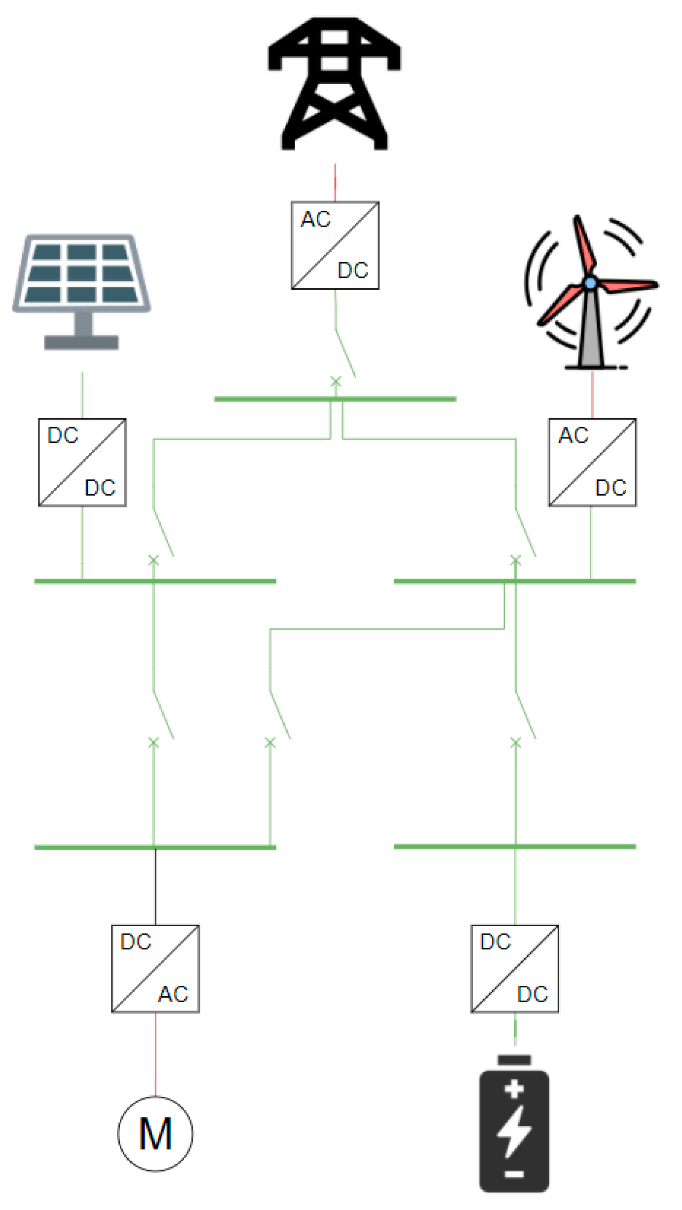
- Easy enhancement of power quality and control of the MG: In DC MGs there are no harmonic oscillations or phase unbalances, which occur in AC MGs and undermine the power quality. Instead, the DC systems provide a “firewall” that prevents disturbances propagating from one network to another, improving the MGs’ robustness [16,17]. Furthermore, since DC MGs operate only with active power, there is no need for reactive power control, in contrast with their AC counterparts [18].
- No needfor synchronization: In DC systems there is no need to synchronize the grid-connected RES with the main AC grid. This can further reduce the operational complexity of the system [19]. On the other hand, in AC MGs the frequency needs to be regulated in order to be constantly kept equal to 50 or 60 Hz giving rise to stability issues.
- No skin effect: In DC systems there is no skin effect. This allows the current’s flow through the entire distribution cable, not just the outer edges. As a result, DC distribution reduces losses and provides the possibility to use smaller cables for the same flow of current [19].
- Lack of specific standards: In order for a system, such as the DC MG to be widely implemented, the definition of certain parameters, such as the voltage levels, need to be specified. Due to the fact that DC applications are not as widespread as AC applications, there is a general lack of standardized values regarding their function. This issue needs to be addressed, in order for the DC MGs to enter the worldwide market [20].
- Protection issues: In the case of DC power, there are protection issues that are not only related to the lack of standards but also to the specific nature of DC current. Specifically, breaking a functioning DC circuit is considered to be more difficult, compared to its AC counterpart, because there is no natural zero crossing of the current, to minimize the arc effect. Major research efforts are undertaken for the development of switchgear that can accommodate the secure disruption of DC voltages in the order of kVs, with low cost, to enable the development of grid infrastructures [18,19].
- Lack of expertise: The existing grids are most commonly AC-based. The AC technology is proven and mature, whereas DC technology is in a process to be established. This means that few specialists, grid developers and system operators have studied DC MGs extensively.
- Construction cost: The overall cost regarding the construction of AC MGs is lower than the respective cost for DC MGs. This occurs because the development of DC technologies, e.g., dedicated power converters, terminals, etc., is more recent and the innovation is integrated into the overall cost.
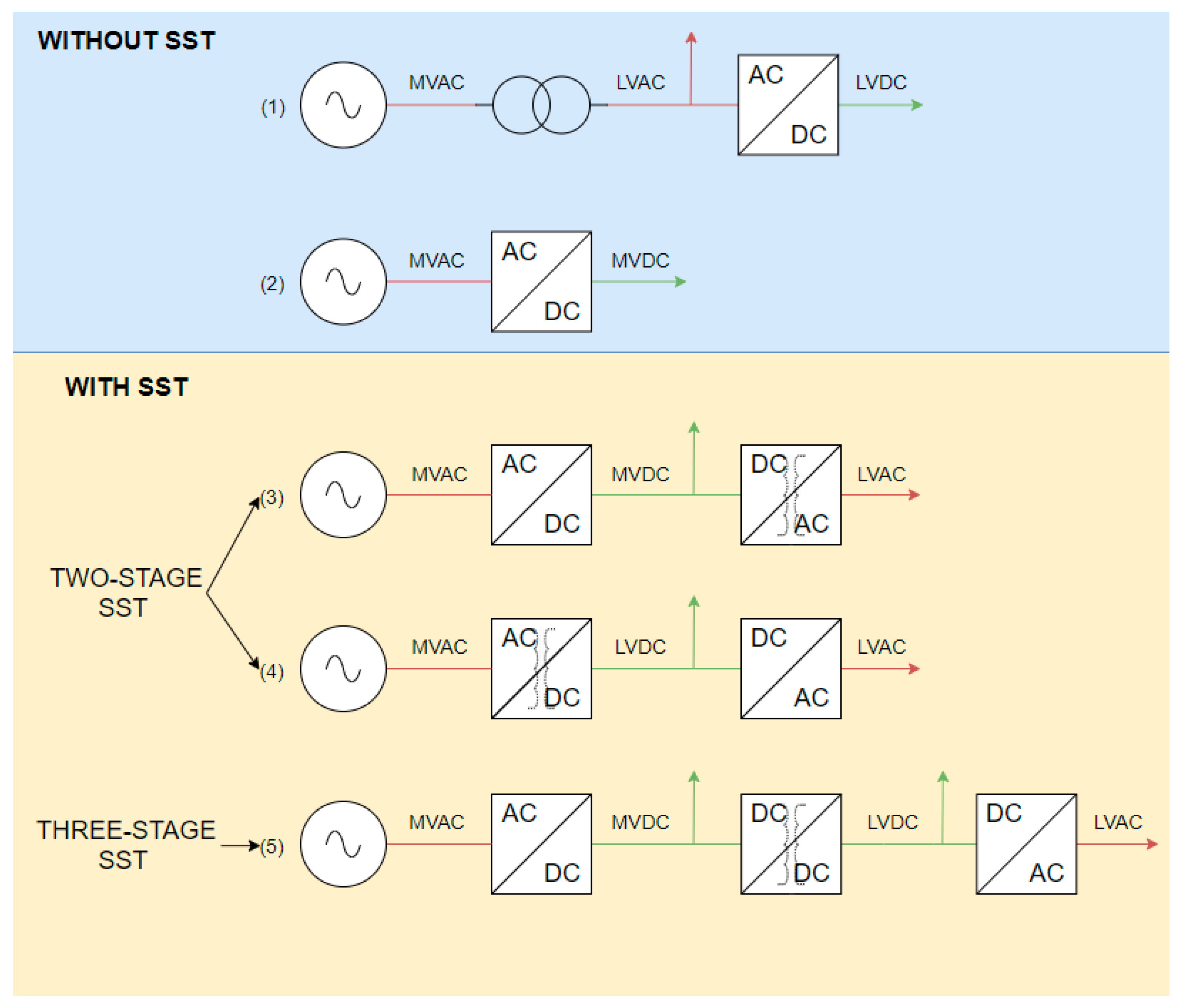
3. Interface with the AC Grid
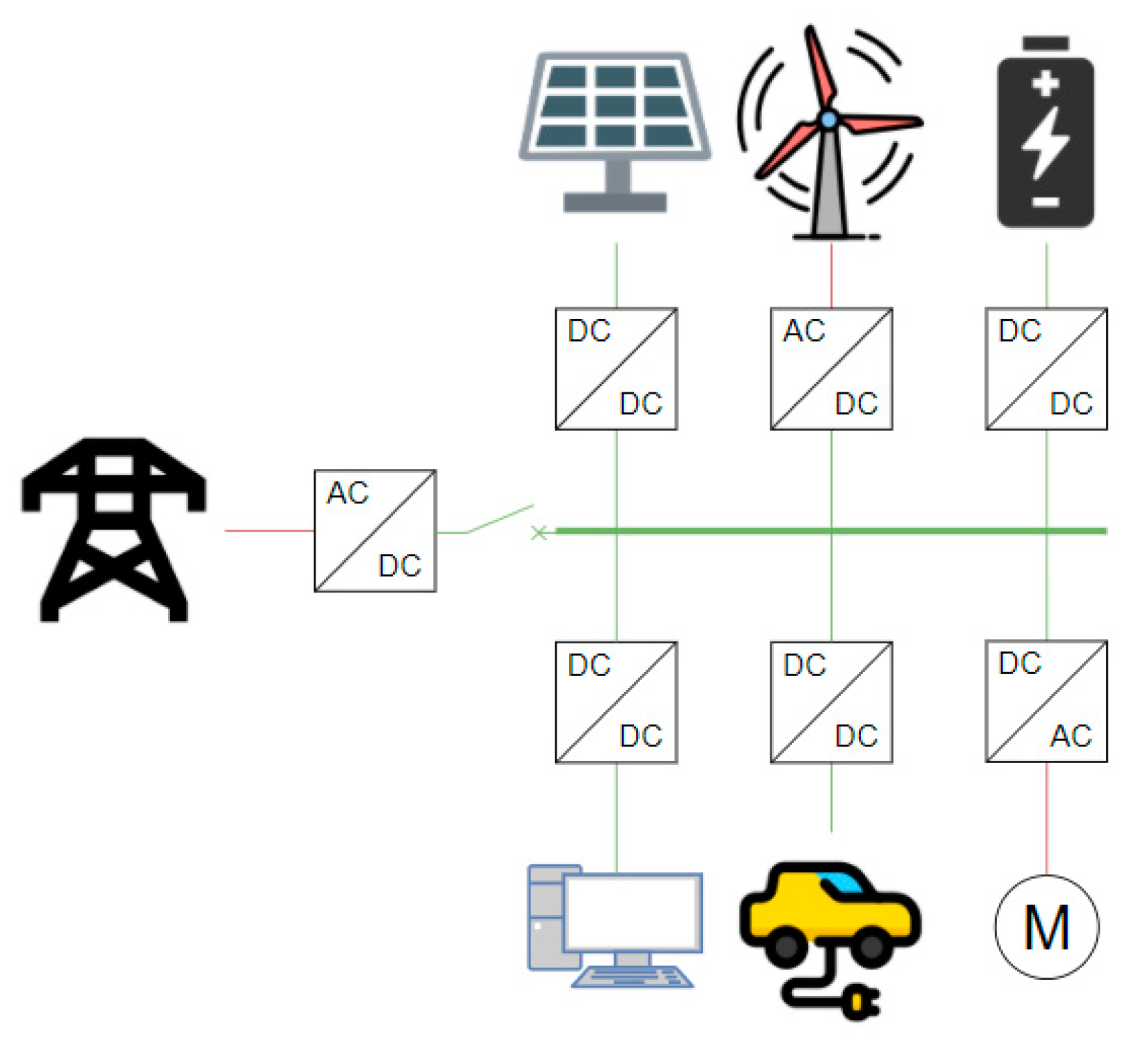
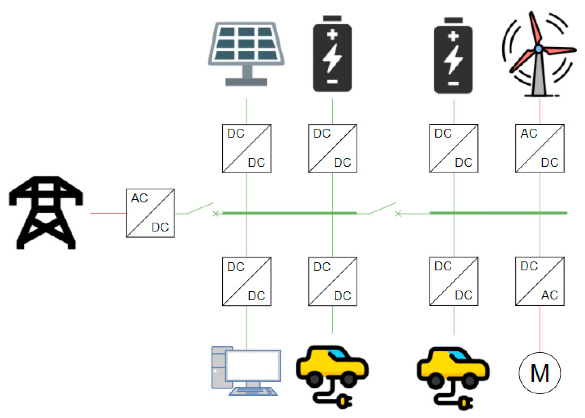
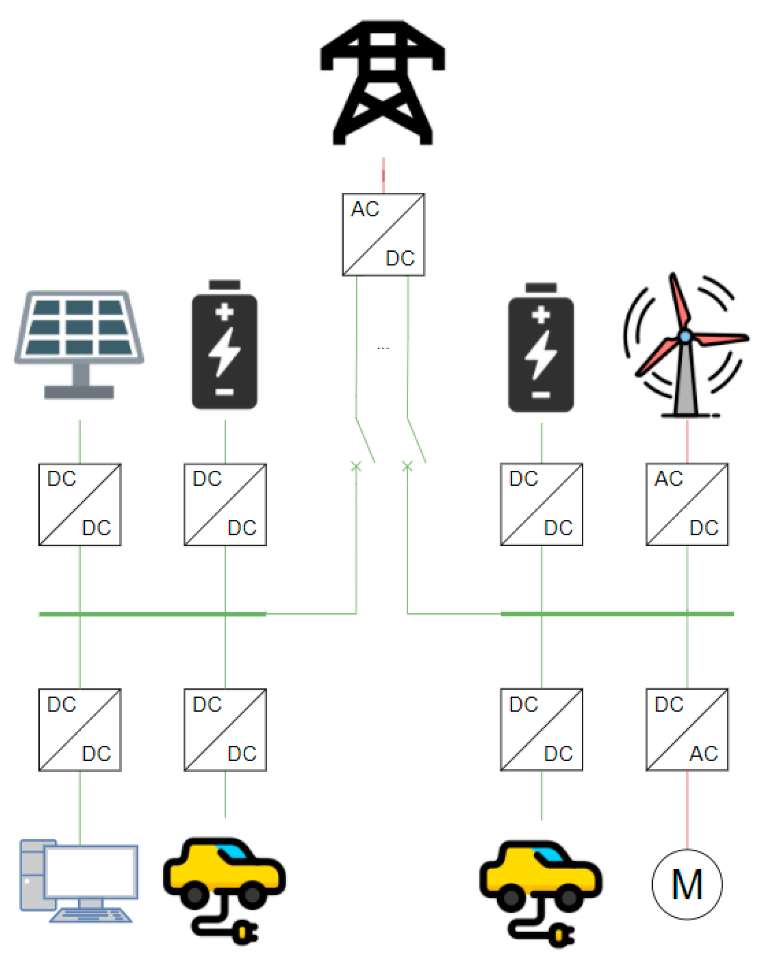
4. Topologies of DC MGs
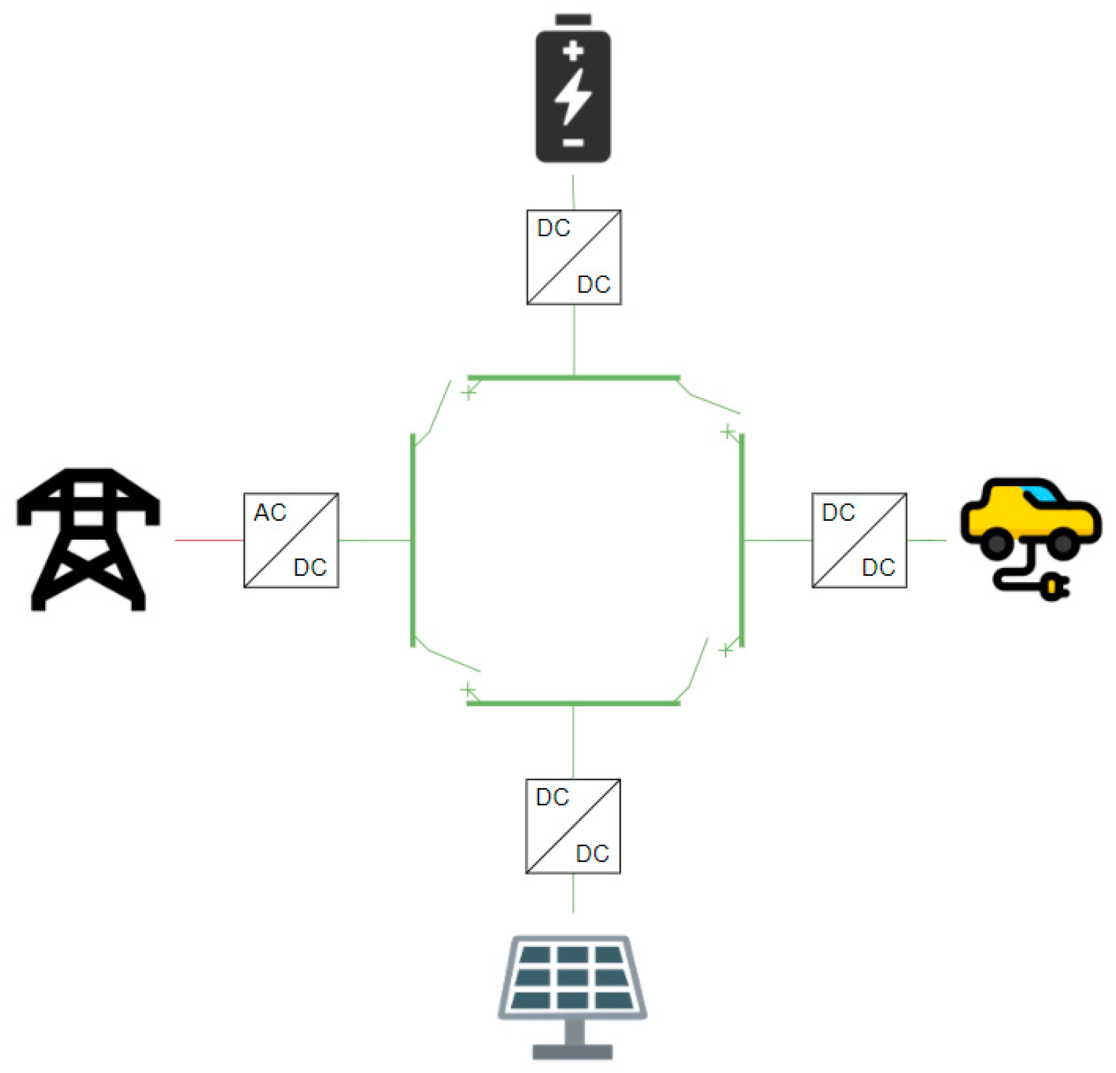
4.1. Single-Bus
4.2. Radial
4.3. Ring
4.4. Mesh
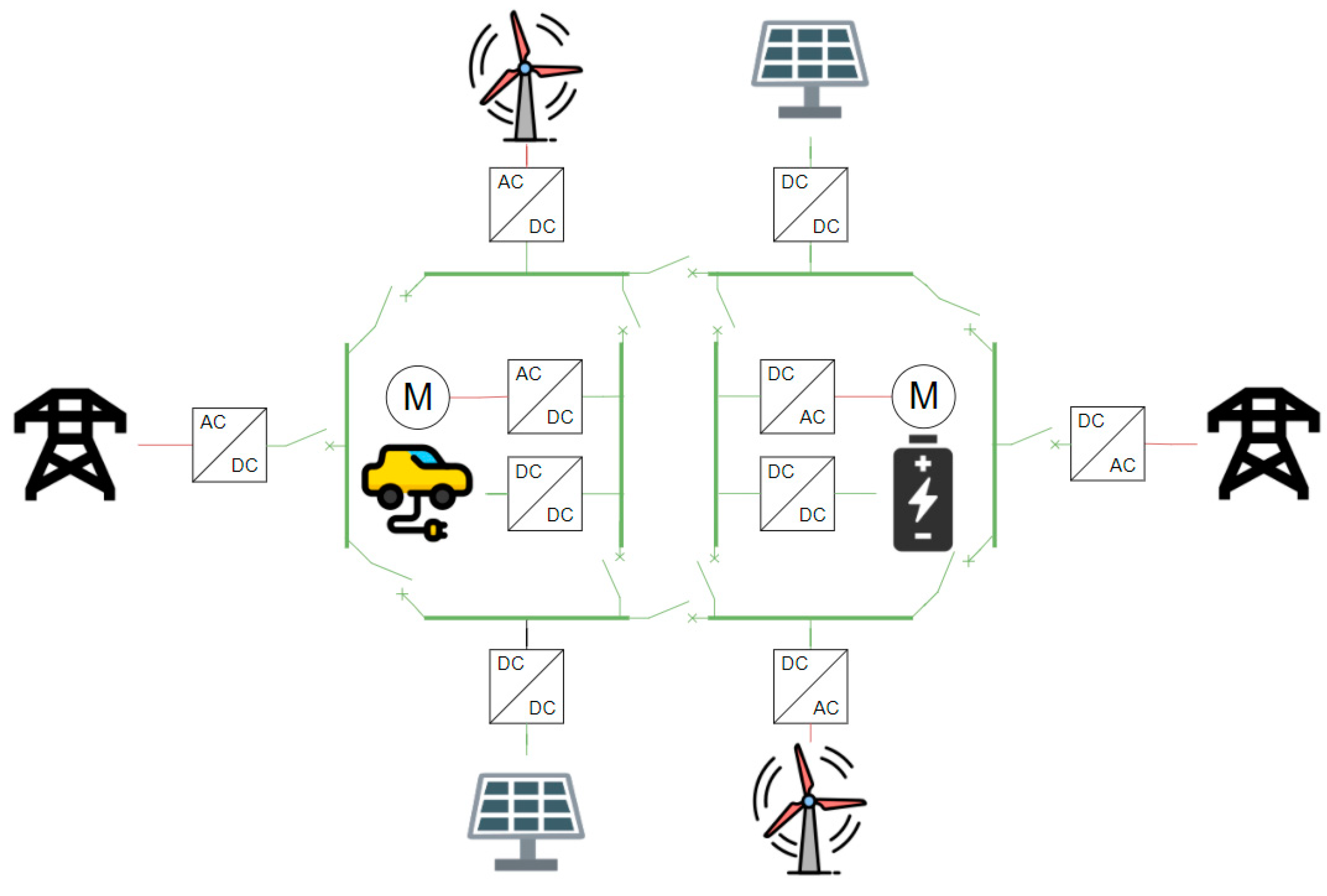
4.5. Interconnected
4.6. Synopsis and Comparison among the Topologies
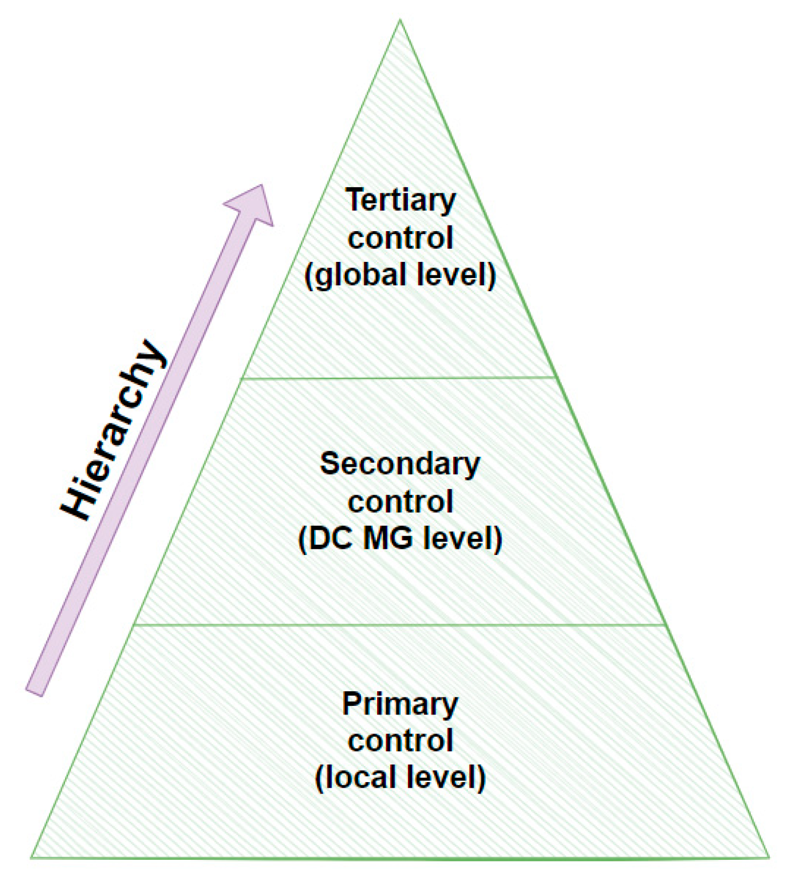
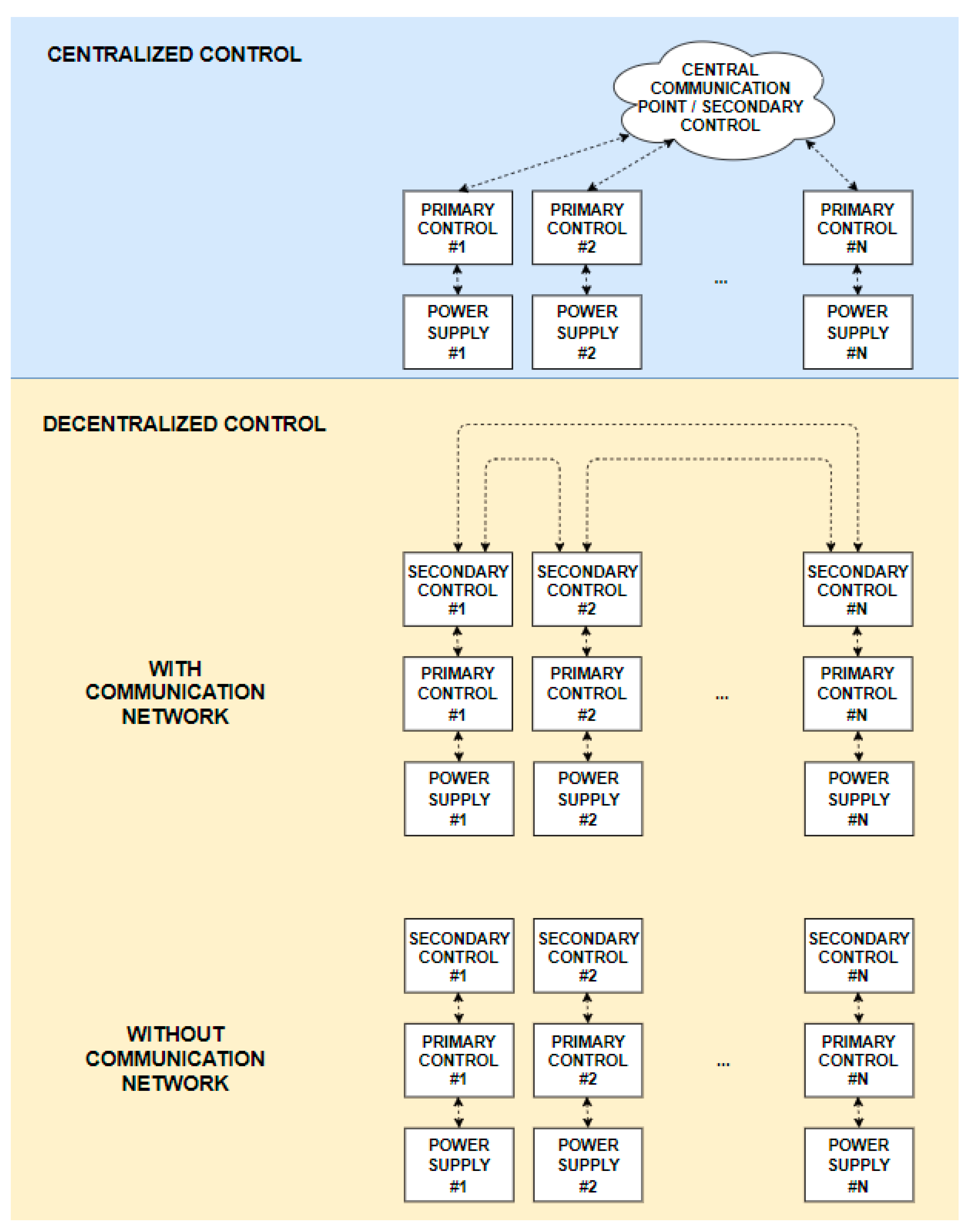
5. Control of DC MGs
- Primary control: This is the lowest hierarchical control level and has the fastest response. It deals with the primary voltage regulation, the load sharing among the distributed generation of the MG and safety/protection issues. The respective DC/DC power converters of the MG undertake the above tasks.
- Secondary control: While the primary control level is responsible for the primary voltage regulation, the secondary control level is responsible for the regulation of voltage fluctuations/deviations [55]. It is also responsible for the seamless reconnection of the MG to the main grid.
- Tertiary control: This is the highest hierarchical control level. It sets the power flow between the DC MG and the main grid. It is also known as an energy management system (EMS) and communicates with the distribution system operator (DSO). In this sense, the DSO, or even the transmission system operator (TSO), may decide the power exchange with the MG.
6. Applications of DC MGs
6.1. Ships and Other Marine Applications
6.2. Transport Applications
6.3. Data Centers
6.4. Building Applications
6.5. Lighting of Public Spaces and Roads
6.6. Electric Vehicles and Charging Stations
6.7. Industrial Applications
6.8. Synopsis of Applications of DC MGs
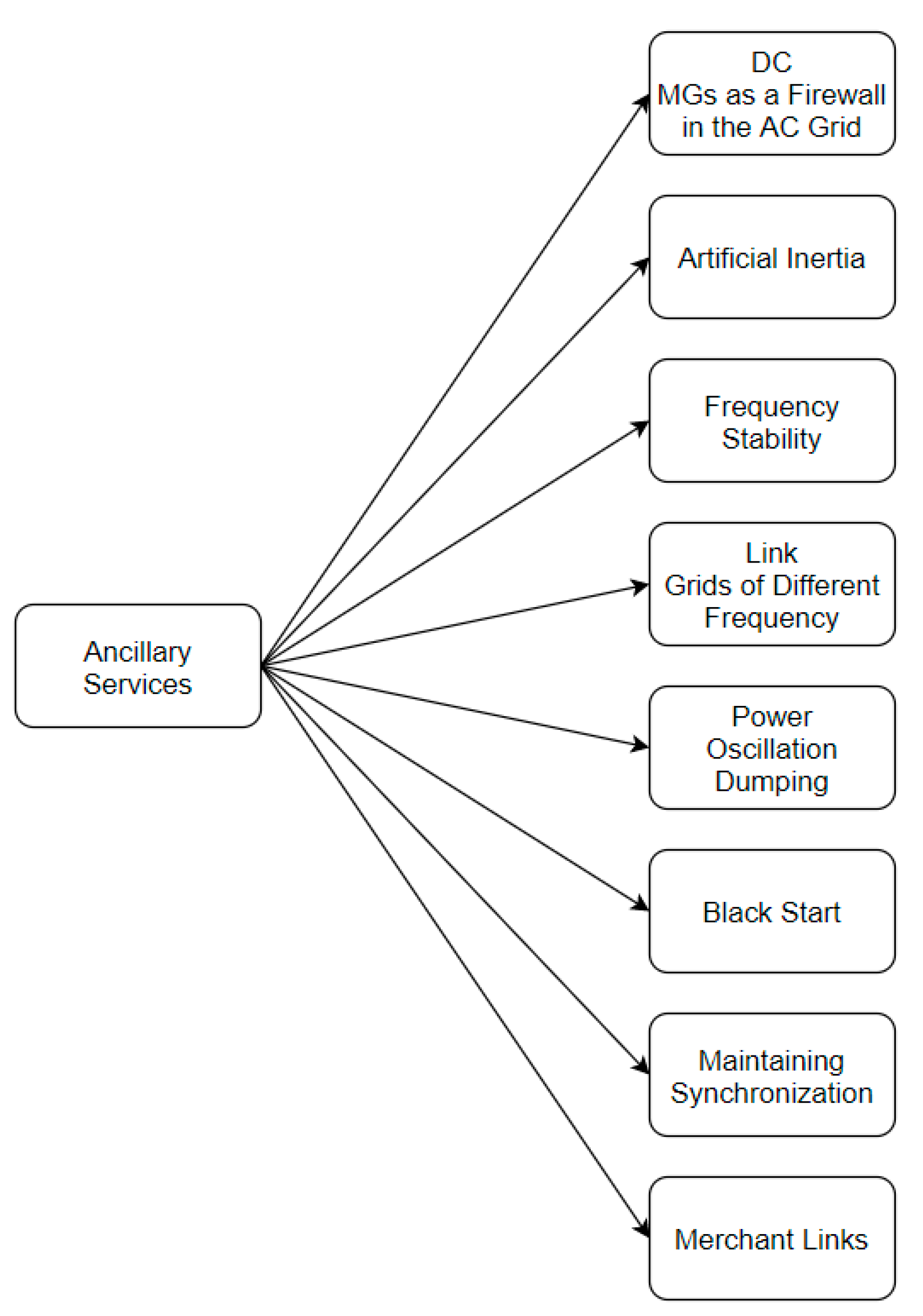
7. Ancillary Services
- DC MGs as a firewall in the AC grid: A DC system between AC grids can act as a “firewall” preventing disturbances spreading from one AC grid to another. When a power imbalance occurs on one part of the AC grid, the DC MG may mitigate the imbalance and prevent the disturbance from propagating to the rest of the network [104].
- Artificial inertia: Weak AC systems may suffer from frequency variations. This results from the low ratio of rotating mass (inertia) related to synchronous machines. In this case, the DC MGs can provide ancillary services by providing additional inertia in order to strengthen the local stability [100].
- Frequency stability: Frequency deviation in an AC grid results from imbalances between produced and consumed power. DC MGs, which have zero frequency, can mitigate the frequency deviation through their converters, thus restoring the frequency stability [101].
- Link grids of different frequency: A DC MG can act as a link between AC grids. The capability of DC systems to offer the desired frequency set-points makes possible the connection of AC grids with different frequencies [101].
- Power oscillation dumping: Electromechanical oscillations of the rotors in the synchronous machines may stress the main AC grid. These oscillations indicate an operating working point close to the stability limit that wears down the governor systems of the turbines. To reduce these oscillations and maintain a safe power transfer, a control signal can be applied to the DC system, which is considered to be a valuable ancillary service according to [105].
- Black-start: Black-start is considered to be an important ancillary service. Due to the interconnected power sources and storage means in a DC MG the restoration process (black-start) of an AC system can be fulfilled after a system power loss or blackout. Additionally, Voltage Source Converter (VSC) transmission technology can follow the cold load pickup as well as the pickup of the power production due to its smooth control of both active and reactive power [95].
- Merchant links: The coupling of electricity markets and growing commercial interconnections requires precise, controllable power flows for effective operation, in line with the market-derived schedules. It is noted that, power scheduling on an hour or minute basis is a common situation. The controllability of active power flow in the DC systems guides the power flow in the AC system to fulfill prearranged commercial deals [107].
8. Future Trends and Challenges
9. Conclusions
Author Contributions
Funding
Institutional Review Board Statement
Informed Consent Statement
Data Availability Statement
Conflicts of Interest
References
- European Commission. State of the Union 2020; European Comission: Brussels, Belgium, 2020. [Google Scholar]
- Agora Energiewende. European Energy Transition 2030: The Big Picture; Agora Engerweide: Berlin, Germany, 2019. [Google Scholar]
- SolarPower Europe. EU Market Outlook for Solar Power/2019–2023; SolarPower Europe: Brussels, Belgium, 2019. [Google Scholar]
- AL Shaqsi, A.Z.; Sopian, K.; Al-Hinai, A. Review of Energy Storage Services, Applications, Limitations, and Benefits. Energy Rep. 2020, 6, 288–306. [Google Scholar] [CrossRef]
- Yang, Y.; Bremner, S.; Menictas, C.; Kay, M. Battery Energy Storage System Size Determination in Renewable Energy Systems: A Review. Renew. Sustain. Energy Rev. 2018, 91, 109–125. [Google Scholar] [CrossRef]
- Freitas Gomes, I.S.; Perez, Y.; Suomalainen, E. Coupling Small Batteries and PV Generation: A Review. Renew. Sustain. Energy Rev. 2020, 126, 109835. [Google Scholar] [CrossRef]
- Normark, B.; Shivakumar, A.; Welsch, M. DC Power Production and Consumption in Households. In Europe’s Energy Transition-Insights for Policy Making; Elsevier: Amsterdam, The Netherlands, 2017; pp. 237–248. ISBN 978-0-12-809806-6. [Google Scholar]
- Kamat, A.S.; Khosla, R.; Narayanamurti, V. Illuminating Homes with LEDs in India: Rapid Market Creation towards Low-Carbon Technology Transition in a Developing Country. Energy Res. Soc. Sci. 2020, 66, 101488. [Google Scholar] [CrossRef]
- Alassi, A.; Bañales, S.; Ellabban, O.; Adam, G.; MacIver, C. HVDC Transmission: Technology Review, Market Trends and Future Outlook. Renew. Sustain. Energy Rev. 2019, 112, 530–554. [Google Scholar] [CrossRef]
- Marzinotto, M.; Mazzanti, G.; Nervi, M. Ground/Sea Return with Electrode Systems for HVDC Transmission. Int. J. Electr. Power Energy Syst. 2018, 100, 222–230. [Google Scholar] [CrossRef]
- Härtel, P.; Vrana, T.K.; Hennig, T.; von Bonin, M.; Wiggelinkhuizen, E.J.; Nieuwenhout, F.D.J. Review of Investment Model Cost Parameters for VSC HVDC Transmission Infrastructure. Electr. Power Syst. Res. 2017, 151, 419–431. [Google Scholar] [CrossRef] [Green Version]
- Ramezanzadeh, S.P.; Mirzaie, M.; Shahabi, M. Reliability Assessment of Different HVDC Transmission System Configurations Considering Transmission Lines Capacity Restrictions and the Effect of Load Level. Int. J. Electr. Power Energy Syst. 2021, 128, 106754. [Google Scholar] [CrossRef]
- Aggeler, D.; Canales, F.; Zelaya-De La Parra, H.; Coccia, A.; Butcher, N.; Apeldoorn, O. Ultra-Fast DC-Charge Infrastructures for EV-Mobility and Future Smart Grids. In Proceedings of the 2010 IEEE PES Innovative Smart Grid Technologies Conference, Gothenburg, Sweden, 11–13 October 2010; pp. 1–8. [Google Scholar]
- Elsayed, A.T.; Mohamed, A.A.; Mohammed, O.A. DC Microgrids and Distribution Systems: An Overview. Electr. Power Syst. Res. 2015, 119, 407–417. [Google Scholar] [CrossRef]
- Ploumpidou, E. Supporting the Transition to DC Micro Grids in the Built Environment 2017; Technische Universiteit Eindhoven: Eindhoven, The Netherlands, 2017. [Google Scholar]
- General Electric Company. High Voltage Direct Current Systems; General Electric Company: New York, NY, USA, 2016. [Google Scholar]
- RTE. PE Interface to AC Grid: Grid Forming Control for a More Resilient Transmission Grid, and a Flexible DC Connection of Grid Customers; RTE: Paris, France, 2020. [Google Scholar]
- Ullah, S.; Haidar, A.M.A.; Hoole, P.; Zen, H.; Ahfock, T. The Current State of Distributed Renewable Generation, Challenges of Interconnection and Opportunities for Energy Conversion Based DC Microgrids. J. Clean. Prod. 2020, 273, 122777. [Google Scholar] [CrossRef]
- Kumar, D.; Zare, F.; Ghosh, A. DC Microgrid Technology: System Architectures, AC Grid Interfaces, Grounding Schemes, Power Quality, Communication Networks, Applications, and Standardizations Aspects. IEEE Access 2017, 5, 12230–12256. [Google Scholar] [CrossRef]
- Chandra, A.; Singh, G.K.; Pant, V. Protection Techniques for DC Microgrid-A Review. Electr. Power Syst. Res. 2020, 187, 106439. [Google Scholar] [CrossRef]
- Unamuno, E.; Barrena, J.A. Hybrid Ac/Dc Microgrids—Part I: Review and Classification of Topologies. Renew. Sustain. Energy Rev. 2015, 52, 1251–1259. [Google Scholar] [CrossRef]
- Ferreira Costa, L.; De Carne, G.; Buticchi, G.; Liserre, M. The Smart Transformer: A Solid-State Transformer Tailored to Provide Ancillary Services to the Distribution Grid. IEEE Power Electron. Mag. 2017, 4, 56–67. [Google Scholar] [CrossRef] [Green Version]
- Falcones, S.; Ayyanar, R.; Mao, X. A DC–DC Multiport-Converter-Based Solid-State Transformer Integrating Distributed Generation and Storage. IEEE Trans. Power Electron. 2013, 28, 2192–2203. [Google Scholar] [CrossRef]
- Patrao, I.; Figueres, E.; Garcerá, G.; González-Medina, R. Microgrid Architectures for Low Voltage Distributed Generation. Renew. Sustain. Energy Rev. 2015, 43, 415–424. [Google Scholar] [CrossRef]
- Mandal, S.; Mandal, K.K. Optimal Energy Management of Microgrids under Environmental Constraints Using Chaos Enhanced Differential Evolution. Renew. Energy Focus 2020, 34, 129–141. [Google Scholar] [CrossRef]
- Nguyen, T.-T.; Yoo, H.-J.; Kim, H.-M. A Comparison Study of MVDC and MVAC for Deployment of Distributed Wind Generations. In Proceedings of the 2016 IEEE International Conference on Sustainable Energy Technologies (ICSET), Hanoi, Vietnam, 14–16 November 2016; pp. 138–141. [Google Scholar]
- Karabiber, A.; Keles, C.; Kaygusuz, A.; Alagoz, B.B. An Approach for the Integration of Renewable Distributed Generation in Hybrid DC/AC Microgrids. Renew. Energy 2013, 52, 251–259. [Google Scholar] [CrossRef]
- Banaei, M.R.; Salary, E. Power Quality Improvement Based on Novel Power Electronic Transformer. In Proceedings of the 2011 2nd Power Electronics, Drive Systems and Technologies Conference, Tehran, Iran, 16–17 February 2011; pp. 286–291. [Google Scholar]
- Ordono, A.; Unamuno, E.; Barrena, J.A.; Paniagua, J. Interlinking Converters and Their Contribution to Primary Regulation: A Review. Int. J. Electr. Power Energy Syst. 2019, 111, 44–57. [Google Scholar] [CrossRef]
- Nguyen, D.-D.; Nguyen, D.-H.; Ta, M.C.; Fujita, G. Sensorless Feedforward Current Control of Dual-Active-Bridge DC/DC Converter for Micro-Grid Applications. IFAC-Pap. Online 2018, 51, 333–338. [Google Scholar] [CrossRef]
- Olowu, T.O.; Jafari, H.; Moghaddami, M.; Sarwat, A.I. Physics-Based Design Optimization of High Frequency Transformers for Solid State Transformer Applications. In Proceedings of the 2019 IEEE Industry Applications Society Annual Meeting, Baltimore, MD, USA, 29 September–3 October 2019; pp. 1–6. [Google Scholar]
- Wang, Y.; Li, Y.; Cao, Y.; Tan, Y.; He, L.; Han, J. Hybrid AC/DC Microgrid Architecture with Comprehensive Control Strategy for Energy Management of Smart Building. Int. J. Electr. Power Energy Syst. 2018, 101, 151–161. [Google Scholar] [CrossRef]
- Fotoohabadi, H.; Mohammadi, M. Evaluating the Technical Benefits of AC–DC Hybrid Distribution Systems Consisting of Solid-State Transformers Using a Multiobjective Index. Sustain. Energy Grids Netw. 2019, 18, 100224. [Google Scholar] [CrossRef]
- Huang, L.; Li, Y.; Cui, Q.; Xie, N.; Zeng, J.; Shu, J. Research on Optimal Configuration of AC/DC Hybrid System Integrated with Multiport Solid-State Transforms and Renewable Energy Based on a Coordinate Strategy. Int. J. Electr. Power Energy Syst. 2020, 119, 105880. [Google Scholar] [CrossRef]
- Dragicevic, T.; Lu, X.; Vasquez, J.C.; Guerrero, J.M. DC Microgrids—Part II: A Review of Power Architectures, Applications, and Standardization Issues. IEEE Trans. Power Electron. 2016, 31, 3528–3549. [Google Scholar] [CrossRef] [Green Version]
- Hatahet, W.; Marei, M.I.; Mokhtar, M. Adaptive Controllers for Grid-Connected DC Microgrids. Int. J. Electr. Power Energy Syst. 2021, 130, 106917. [Google Scholar] [CrossRef]
- Singh, P.; Lather, J.S. Power Management and Control of a Grid-Independent DC Microgrid with Hybrid Energy Storage System. Sustain. Energy Technol. Assess. 2021, 43, 100924. [Google Scholar] [CrossRef]
- Liu, Z.; Zhao, J.; Zou, Z. Impedance Modeling, Dynamic Analysis and Damping Enhancement for DC Microgrid with Multiple Types of Loads. Int. J. Electr. Power Energy Syst. 2020, 122, 106183. [Google Scholar] [CrossRef]
- Asad, R.; Kazemi, A. A Novel Distributed Optimal Power Sharing Method for Radial Dc Microgrids with Different Distributed Energy Sources. Energy 2014, 72, 291–299. [Google Scholar] [CrossRef]
- Yu, H.; Niu, S.; Zhang, Y.; Jian, L. An Integrated and Reconfigurable Hybrid AC/DC Microgrid Architecture with Autonomous Power Flow Control for Nearly/Net Zero Energy Buildings. Appl. Energy 2020, 263, 114610. [Google Scholar] [CrossRef]
- Abdali, A.; Mazlumi, K.; Noroozian, R. High-Speed Fault Detection and Location in DC Microgrids Systems Using Multi-Criterion System and Neural Network. Appl. Soft Comput. 2019, 79, 341–353. [Google Scholar] [CrossRef]
- Meghwani, A.; Gokaraju, R.; Srivastava, S.C.; Chakrabarti, S. Local Measurements-Based Backup Protection for DC Microgrids Using Sequential Analyzing Technique. IEEE Syst. J. 2020, 14, 1159–1170. [Google Scholar] [CrossRef]
- Tiwari, S.P.; Koley, E.; Ghosh, S. Communication-Less Ensemble Classifier-Based Protection Scheme for DC Microgrid with Adaptiveness to Network Reconfiguration and Weather Intermittency. Sustain. Energy Grids Netw. 2021, 26, 100460. [Google Scholar] [CrossRef]
- Lee, G.-Y.; Ko, B.-S.; Lee, J.-S.; Kim, R.-Y. An Off-Line Design Methodology of Droop Control for Multiple Bi-Directional Distributed Energy Resources Based on Voltage Sensitivity Analysis in DC Microgrids. Int. J. Electr. Power Energy Syst. 2020, 118, 105754. [Google Scholar] [CrossRef]
- Sallam, A.M.; Ahmed, H.M.A.; Salama, M.M.A. A Planning Framework for AC-DC Bilayer Microgrids. Electr. Power Syst. Res. 2020, 188, 106524. [Google Scholar] [CrossRef]
- Ciezki, J.G.; Ashton, R.W. Selection and Stability Issues Associated with a Navy Shipboard DC Zonal Electric Distribution System. IEEE Trans. Power Deliv. 2000, 15, 665–669. [Google Scholar] [CrossRef]
- Baran, M.E.; Mahajan, N. System Reconfiguration on Shipboard DC Zonal Electrical System. In Proceedings of the IEEE Electric Ship Technologies Symposium, Philadelphia, PA, USA, 27 July 2005; pp. 86–92. [Google Scholar]
- Feng, X.; Butler-Purry, K.L.; Zourntos, T. Real-Time Electric Load Management for DC Zonal All-Electric Ship Power Systems. Electr. Power Syst. Res. 2018, 154, 503–514. [Google Scholar] [CrossRef]
- van der Blij, N.H.; Ramirez-Elizondo, L.M.; Spaan, M.T.J.; Bauer, P. Grid Sense Multiple Access: A Decentralized Control Algorithm for DC Grids. Int. J. Electr. Power Energy Syst. 2020, 119, 105818. [Google Scholar] [CrossRef]
- Bandyopadhyay, S.; Ramirez-Elizondo, L.; Bauer, P. Stability Constrained Gain Optimization of Droop Controlled Converters in DC Nanogrids. In Proceedings of the 2018 International Power Electronics Conference (IPEC-Niigata 2018 -ECCE Asia), Niigata, Japan, 20–24 May 2018; pp. 1426–1434. [Google Scholar]
- Van Der Blij, N.H.; Ramirez-Elizondo, L.M.; Spaan, M.T.J.; Bauer, P. Stability and Decentralized Control of Plug-and-Play DC Distribution Grids. IEEE Access 2018, 6, 63726–63736. [Google Scholar] [CrossRef]
- Armghan, A.; Azeem, M.K.; Armghan, H.; Yang, M.; Alenezi, F.; Hassan, M. Dynamical Operation Based Robust Nonlinear Control of DC Microgrid Considering Renewable Energy Integration. Energies 2021, 14, 3988. [Google Scholar] [CrossRef]
- Vasantharaj, S.; Indragandhi, V.; Subramaniyaswamy, V.; Teekaraman, Y.; Kuppusamy, R.; Nikolovski, S. Efficient Control of DC Microgrid with Hybrid PV—Fuel Cell and Energy Storage Systems. Energies 2021, 14, 3234. [Google Scholar] [CrossRef]
- Trinh, P.-H.; Chung, I.-Y. Optimal Control Strategy for Distributed Energy Resources in a DC Microgrid for Energy Cost Reduction and Voltage Regulation. Energies 2021, 14, 992. [Google Scholar] [CrossRef]
- Papadimitriou, C.N.; Zountouridou, E.I.; Hatziargyriou, N.D. Review of Hierarchical Control in DC Microgrids. Electr. Power Syst. Res. 2015, 122, 159–167. [Google Scholar] [CrossRef]
- Unamuno, E.; Barrena, J.A. Hybrid Ac/Dc Microgrids—Part II: Review and Classification of Control Strategies. Renew. Sustain. Energy Rev. 2015, 52, 1123–1134. [Google Scholar] [CrossRef]
- Lu, X.; Guerrero, J.M.; Sun, K.; Vasquez, J.C. An Improved Droop Control Method for DC Microgrids Based on Low Bandwidth Communication with DC Bus Voltage Restoration and Enhanced Current Sharing Accuracy. IEEE Trans. Power Electron. 2014, 29, 1800–1812. [Google Scholar] [CrossRef] [Green Version]
- Guerrero, J.M.; Vasquez, J.C.; Matas, J.; de Vicuna, L.G.; Castilla, M. Hierarchical Control of Droop-Controlled AC and DC Microgrids—A General Approach toward Standardization. IEEE Trans. Ind. Electron. 2011, 58, 158–172. [Google Scholar] [CrossRef]
- Zammit, D.; Staines, C.S.; Micallef, A.; Apap, M.; Licari, J. Incremental Current Based MPPT for a PMSG Micro Wind Turbine in a Grid-Connected DC Microgrid. Energy Procedia 2017, 142, 2284–2294. [Google Scholar] [CrossRef]
- Priyadarshini, L.; Dash, P.K.; Dhar, S. A New Exponentially Expanded Robust Random Vector Functional Link Network Based MPPT Model for Local Energy Management of PV-Battery Energy Storage Integrated Microgrid. Eng. Appl. Artif. Intell. 2020, 91, 103633. [Google Scholar] [CrossRef]
- Vandoorn, T.L.; De Kooning, J.D.M.; Meersman, B.; Vandevelde, L. Review of Primary Control Strategies for Islanded Microgrids with Power-Electronic Interfaces. Renew. Sustain. Energy Rev. 2013, 19, 613–628. [Google Scholar] [CrossRef]
- Mortezapour, V.; Lesani, H. Hybrid AC/DC Microgrids: A Generalized Approach for Autonomous Droop-Based Primary Control in Islanded Operations. Int. J. Electr. Power Energy Syst. 2017, 93, 109–118. [Google Scholar] [CrossRef]
- Arul, P.G.; Ramachandaramurthy, V.K.; Rajkumar, R.K. Control Strategies for a Hybrid Renewable Energy System: A Review. Renew. Sustain. Energy Rev. 2015, 42, 597–608. [Google Scholar] [CrossRef]
- Ortiz, L.; González, J.W.; Gutierrez, L.B.; Llanes-Santiago, O. A Review on Control and Fault-Tolerant Control Systems of AC/DC Microgrids. Heliyon 2020, 6, e04799. [Google Scholar] [CrossRef]
- Dragicevic, T.; Lu, X.; Vasquez, J.; Guerrero, J. DC Microgrids–Part I: A Review of Control Strategies and Stabilization Techniques. IEEE Trans. Power Electron. 2015, 31, 4876–4891. [Google Scholar] [CrossRef] [Green Version]
- Li, P.; Guo, T.; Li, Y.; Han, X.; Wang, P.; Li, X.; Wang, Z. An Adaptive Coordinated Optimal Control Method for Parallel Bidirectional Power Converters in AC/DC Hybrid Microgrid. Int. J. Electr. Power Energy Syst. 2021, 126, 106596. [Google Scholar] [CrossRef]
- Dimeas, A.; Tsikalakis, A.; Kariniotakis, G.; Korres, G. Microgrids Control Issues. In Microgrids; Hatziargyriou, N., Ed.; John Wiley and Sons Ltd.: Chichester, UK, 2013; pp. 25–80. ISBN 978-1-118-72067-7. [Google Scholar]
- Aprilia, E.; Meng, K.; Zeineldin, H.H.; Hosani, M.A.; Dong, Z.Y. Modeling of Distributed Generators and Converters Control for Power Flow Analysis of Networked Islanded Hybrid Microgrids. Electr. Power Syst. Res. 2020, 184, 106343. [Google Scholar] [CrossRef]
- Shafiee, Q.; Guerrero, J.M.; Vasquez, J.C. Distributed Secondary Control for Islanded Microgrids—A Novel Approach. IEEE Trans. Power Electron. 2014, 29, 1018–1031. [Google Scholar] [CrossRef] [Green Version]
- Hu, J.; Shan, Y.; Guerrero, J.M.; Ioinovici, A.; Chan, K.W.; Rodriguez, J. Model Predictive Control of Microgrids–An Overview. Renew. Sustain. Energy Rev. 2021, 136, 110422. [Google Scholar] [CrossRef]
- Beus, M.; Banis, F.; Pandžić, H.; Poulsen, N.K. Three-Level Hierarchical Microgrid Control—Model Development and Laboratory Implementation. Electr. Power Syst. Res. 2020, 189, 106758. [Google Scholar] [CrossRef]
- Mazidi, M.; Rezaei, N.; Ardakani, F.J.; Mohiti, M.; Guerrero, J.M. A Hierarchical Energy Management System for Islanded Multi-Microgrid Clusters Considering Frequency Security Constraints. Int. J. Electr. Power Energy Syst. 2020, 121, 106134. [Google Scholar] [CrossRef]
- Wu, T.; Wang, J. Artificial Intelligence for Operation and Control: The Case of Microgrids. Electr. J. 2021, 34, 106890. [Google Scholar] [CrossRef]
- Faddel, S.; Saad, A.A.; Mohammed, O. Decentralized Energy Management of Hybrid Energy Storage on MVDC Shipboard Power System. In Proceedings of the 2018 IEEE Industry Applications Society Annual Meeting (IAS), Portland, OR, USA, 23–27 September 2018; pp. 1–7. [Google Scholar]
- Mills, A.J.; Ashton, R.W. Adaptive, Sparse, and Multi-Rate LQR Control of an MVDC Shipboard Power System with Constant Power Loads. In Proceedings of the 2017 IEEE International Conference on Industrial Technology (ICIT), Toronto, ON, Canada, 22–25 March 2017; pp. 498–503. [Google Scholar]
- Vu, T.V.; Gonsoulin, D.; Perkins, D.; Papari, B.; Vahedi, H.; Edrington, C.S. Distributed Control Implementation for Zonal MVDC Ship Power Systems. In Proceedings of the 2017 IEEE Electric Ship Technologies Symposium (ESTS), Arlington, VA, USA, 14–17 August 2017; pp. 539–543. [Google Scholar]
- Shekhar, A.; Ramirez-Elizondo, L.; Bauer, P. DC Microgrid Islands on Ships. In Proceedings of the 2017 IEEE Second International Conference on DC Microgrids (ICDCM), Nuremburg, Germany, 27–29 June 2017; pp. 111–118. [Google Scholar]
- Verdicchio, A.; Ladoux, P.; Caron, H.; Courtois, C. New Medium-Voltage DC Railway Electrification System. IEEE Trans. Transp. Electrific. 2018, 4, 591–604. [Google Scholar] [CrossRef]
- ABB. Medium Voltage Products, Technical Application Papers No. 24-Medium Voltage Direct Current Applications; ABB: Zurich, Switzerland, 2017. [Google Scholar]
- AlLee, G.; Tschudi, W. Edison Redux: 380 Vdc Brings Reliability and Efficiency to Sustainable Data Centers. IEEE Power Energy Mag. 2012, 10, 50–59. [Google Scholar] [CrossRef]
- Pratt, A.; Kumar, P.; Aldridge, T.V. Evaluation of 400V DC Distribution in Telco and Data Centers to Improve Energy Efficiency. In Proceedings of the 29th International Telecommunications Energy Conference, Rome, Italy, 30 September–4 October 2007; pp. 32–39. [Google Scholar]
- Jhunjhunwala, A.; Lolla, A.; Kaur, P. Solar-Dc Microgrid for Indian Homes: A Transforming Power Scenario. IEEE Electrific. Mag. 2016, 4, 10–19. [Google Scholar] [CrossRef]
- Fregosi, D.; Ravula, S.; Brhlik, D.; Saussele, J.; Frank, S.; Bonnema, E.; Scheib, J.; Wilson, E. A Comparative Study of DC and AC Microgrids in Commercial Buildings across Different Climates and Operating Profiles. In Proceedings of the 2015 IEEE First International Conference on DC Microgrids (ICDCM), Atlanta, GA, USA, 7–10 June 2015; pp. 159–164. [Google Scholar]
- Li, W.; Mou, X.; Zhou, Y.; Marnay, C. On Voltage Standards for DC Home Microgrids Energized by Distributed Sources. In Proceedings of the Proceedings of The 7th International Power Electronics and Motion Control Conference, Harbin, China, 2–5 June 2012; Volume 3, pp. 2282–2286. [Google Scholar]
- Liang, D.; Zou, J.; Wang, Z.; Yang, B. Research on DC Vacuum Switch of Micro-Grid in Road Lighting. In Proceedings of the 2018 2nd IEEE Advanced Information Management, Communicates, Electronic and Automation Control Conference (IMCEC), Xi’an, China, 25–27 May 2018; pp. 242–246. [Google Scholar]
- Quintana, P.J.; Huerta, N.; Rico-Secades, M.; Calleja, A.J.; Corominas, E.L. Control of Public Dc Street/Road Lighting Microgrids with Microgeneration and Storage Capability Based on a Power-Line Signaling Dependent Droop. In Proceedings of the 2016 13th International Conference on Power Electronics (CIEP), Guanajuato, Mexico, 20–23 June 2016; pp. 98–103. [Google Scholar]
- Vaidya, M.; Stefanakos, E.K.; Krakow, B.; Lamb, H.C.; Arbogast, T.; Smith, T. Direct DC-DC Electric Vehicle Charging with a Grid Connected Photovoltaic System. In Proceedings of the Conference Record of the Twenty Fifth IEEE Photovoltaic Specialists Conference-1996, Washington, DC, USA, 13–17 May 1996; pp. 1505–1508. [Google Scholar]
- Senfelds, A.; Apse-Apsitis, P.; Avotins, A.; Ribickis, L.; Hauf, D. Industrial DC Microgrid Analysis with Synchronous Multipoint Power Measurement Solution. In Proceedings of the 2017 19th European Conference on Power Electronics and Applications (EPE’17 ECCE Europe), Warsaw, Poland, 11–14 September 2017; pp. P.1–P.6. [Google Scholar]
- Ailway, R. ABB’s Substation Installations for the Rail Industry Provide Reliable Power to the Line and the Vehicle, to Keep Main Line Trains, Metros and Mass Transit Networks on Track. Optimized Railway Electrification Solutions Ensure Availability and Dependability of AC and DC Power Supply to Enable High Performance and Efficiency; ABB Group: Zurich, Switzerland, 2017; p. 8. [Google Scholar]
- California Energy Commission. Electric Vehicle Charging 101; California Energy Commision: Sacramento, CA, USA, 2021.
- Siraj, K.; Khan, H.A. DC Distribution for Residential Power Networks—A Framework to Analyze the Impact of Voltage Levels on Energy Efficiency. Energy Rep. 2020, 6, 944–951. [Google Scholar] [CrossRef]
- Anand, S.; Fernandes, B.G. Optimal Voltage Level for DC Microgrids. In Proceedings of the IECON 2010-36th Annual Conference on IEEE Industrial Electronics Society, Glendale, AZ, USA, 7–10 November 2010; pp. 3034–3039. [Google Scholar]
- Feng, C.; Wang, S.; Mu, Q. Chapter 21 DC grid power flow control devices. In HVDC Grids: For Offshore and Supergrid of the Future; Wiley-IEEE Press: Hoboken, NJ, USA, 2016; p. 528. ISBN 978-1-118-85915-5. [Google Scholar]
- ENTSO-E. Network Code for Requirements for Grid Connection Applicable to All Generators; ENTSO-E: Brussels, Belgium, 2013. [Google Scholar]
- Hodel, C.; Beck, M. Overview of Ancillary Services, Switzerland. 2010. Available online: https://www.swissgrid.ch/dam/swissgrid/customers/topics/ancillary-services/as-documents/AS-concept-V1-1-en.pdf (accessed on 29 July 2021).
- Hirst, E.; Kirby, B. Electric-Power Ancillary Services. Oak Ridge Natl. Lab. 1996, 9, 26–30. [Google Scholar] [CrossRef]
- Lavoine, O.; Regairaz, F.; Baker, T. Ancillary Services: An Overview of International Practices; Electra: Guilin City, China, 2009; Volume 252, pp. 86–91. [Google Scholar]
- Renner, R.H.; Van Hertem, D. Ancillary Services in Electric Power Systems with HVDC Grids. IET Gener. Transm. Amp Distrib. 2015, 9, 1179–1185. [Google Scholar] [CrossRef]
- Kaushal, A.; Hertem, D.V. An Overview of Ancillary Services and HVDC Systems in European Context. Energies 2019, 12, 3481. [Google Scholar] [CrossRef] [Green Version]
- Tielens, P.; Van Hertem, D. The Relevance of Inertia in Power Systems. Renew. Sustain. Energy Rev. 2016, 55, 999–1009. [Google Scholar] [CrossRef]
- ENTSO-E. Need for Synthetic Inertia (SI) for Frequency Regulation. Available online: https://consultations.entsoe.eu/system-development/entso-e-connection-codes-implementation-guidance-d-4/user_uploads/6---igd-on-si.pdf (accessed on 29 July 2021).
- ENTSO-E. Balancing and Ancillary Services Markets. Available online: https://www.entsoe.eu/about/market/#balancing-and-ancillary-services-markets (accessed on 29 July 2021).
- Pentayya, P.; Gartia, A.; Das, A.P.; Kumar, C. Black Start Exercises Experience in Western Region, India. In Proceedings of the 2013 Annual IEEE India Conference (INDICON), Mumbai, India, 13–15 December 2013; pp. 1–5. [Google Scholar]
- Corsi, S. Voltage Control and Protection in Electrical Power Systems; Springer: London, UK, 2015; pp. 163–190. ISBN 978-1-4471-6636-8. [Google Scholar]
- Dominguez-Garcia, J.L.; Ugalde-Loo, C.E. Chapter 19 Power system oscillation damping by means of VSC-HVDC systems. In HVDC Grids: For Offshore and Supergrid of the Future; Wiley-IEEE Press: Hoboken, NJ, USA, 2016; p. 528. ISBN 978-1-118-85915-5. [Google Scholar]
- Yusoff, N.I.; Zin, A.A.M.; Bin Khairuddin, A. Congestion Management in Power System: A Review. In Proceedings of the 2017 3rd International Conference on Power Generation Systems and Renewable Energy Technologies (PGSRET), Johor Bahru, Malaysia, 4–6 April 2017; IEEE: Johor Bahru, Malasyia, 2017; pp. 22–27. [Google Scholar]
- ABB. Review HVDC Special Report. Available online: https://library.e.abb.com/public/aff841e25d8986b5c1257d380045703f/140818%20ABB%20SR%2060%20years%20of%20HVDC_72dpi.pdf (accessed on 27 July 2021).
- Establishing a Network Code on Equirements for Grid Connection of High Voltage Direct Current Systems and Direct Current-Connected Power Park Modules, Commission Regulation (EU) 2016/1447. Available online: https://eur-lex.europa.eu/eli/reg/2016/1447/oj (accessed on 29 July 2021).
- PV Tech. The State of Medium Voltage DC Architectures for Utility-Scale PV; PV Tech: London, UK, 2020. [Google Scholar]
- IEEE European Public Policy Initiative. DC Electricity Distribution in the European Union: An Opportunity for Energy Efficiency in Europe; IEEE: Piscataway, NJ, USA, 2017. [Google Scholar]
- De Doncker, R.W. Energy System Transition and DC Hybrid Power Systems; RWTH Aachen University: Aachen, Germany, 2018. [Google Scholar]
- Mo, R.; Li, R.; Li, H. Isolated Modular Multilevel (IMM) DC/DC Converter with Energy Storage and Active Filter Function for Shipboard MVDC System Applications. In Proceedings of the 2015 IEEE Electric Ship Technologies Symposium (ESTS), Old Town Alexandria, VA, USA, 21–24 June 2015; pp. 113–117. [Google Scholar]
- SuperNode. Superconductors for Bulk Power Transfer; SuperNode: Dublin, Ireland, 2020. [Google Scholar]
- Mackay, L.; Shekhar, A.; Roodenburg, B.; Ramirez-Elizondo, L.; Bauer, P. Series Arc Extinction in DC Microgrids Using Load Side Voltage Drop Detection. In Proceedings of the 2015 IEEE First International Conference on DC Microgrids (ICDCM), Atlanta, GA, USA, 7–10 June 2015; pp. 239–244. [Google Scholar]
- Shekhar, A.; Mackay, L.; Ramirez-Elizondo, L.; Bauer, P. DC Microgrid Protection by Selective Detection of Series Arcing Using Load Side Power Electronic Devices. In Proceedings of the 2016 18th European Conference on Power Electronics and Applications (EPE’16 ECCE Europe), Karlsruhe, Germany, 5–9 September 2016; pp. 1–9. [Google Scholar]
- Park, J.; Byun, H.; Kim, S.; Kim, S.; Won, C. DC Solid-State Circuit Breakers with Two-Winding Coupled Inductor for DC Microgrid. Energies 2021, 14, 4129. [Google Scholar] [CrossRef]
- Grcić, I.; Pandžić, H.; Novosel, D. Fault Detection in DC Microgrids Using Short-Time Fourier Transform. Energies 2021, 14, 277. [Google Scholar] [CrossRef]
- International Electrotechnical Commission. IEC 60850 Railway Applications–Supply Voltages of Traction Systems; International Electrotechnical Commission: Geneva, Switzerland, 2014. [Google Scholar]
- International Electrotechnical Commission. IEC 60077-3:2019 Railway Applications-Electric Equipment for Rolling Stock-Part 3: Electrotechnical Components-Rules for DC Circuit-Breakers; International Electrotechnical Commission: Geneva, Switzerland, 2019. [Google Scholar]
- International Electrotechnical Commission. IEC 61992-3:2006 Railway Applications-Fixed Installations-DC Switchgear-Part 3: Indoor d.c. Disconnectors, Switch-Disconnectors and Earthing Switches; International Electrotechnical Commission: Geneva, Switzerland, 2016. [Google Scholar]
- IEEE Standards Association. IEEE 1653.6-2018-IEEE Recommended Practice for Grounding of DC Equipment Enclosures in Traction Power Distribution Facilities; IEEE: Piscatawy, NJ, USA, 2018. [Google Scholar]
- IEEE Std 1709-2018 (Revision of IEEE Std 1709-2010): IEEE Recommended Practice for 1 KV to 35 KV Medium-Voltage DC Power Systems on Ships; IEEE: Piscataway, NJ, USA, 2018; ISBN 978-1-5044-5201-4.
- MIL-STD-1399/390, Military Standard: Interface Standard for Shipboard Systems (Section 390) Electric Power, Direct Currnt, (Other Than Ship’s Battery) for Submarines; Department of the Navy Naval Sea Systems Command: Washington, DC, USA, 1987.
- Environmental Engineering (EE). Power Supply Interface at the Input to Telecommunications and Datacom (ICT) Equipment; Part 3: Operated by Rectified Current Source, Alternating Current Source or Direct Current Source up to 400 V.; Sub-Part 1: Direct Current Source up to 400 V; Environmental Engineering (EE): Valbonne, France, 2011. [Google Scholar]
- International Electrotechnical Commission. IEC 61660-1:1997 Short-Circuit Currents in d.c. Auxiliary Installations in Power Plants and Substations-Part 1: Calculation of Short-Circuit Currents; International Electrotechnical Commission: Geneva, Switzerland, 1997. [Google Scholar]
- International Electrotechnical Commission. IEC 60204-11:2018 Safety of Machinery—Electrical Equipment of Machines-Part 11: Requirements for Equipment for Voltages above 1 000 V AC or 1 500 V DC and Not Exceeding 36 KV; International Electrotechnical Commission: Geneva, Switzerland, 2018. [Google Scholar]
- International Electrotechnical Commission. IEC 60947-2 Low-Voltage Switchgear and Controlgear–Part 2: Circuit-Breakers; International Electrotechnical Commission: Geneva, Switzerland, 2003. [Google Scholar]
- IEEE Standards Association. IEEE C37.14-2015-IEEE Standard for DC (3200 V and below) Power Circuit Breakers Used in Enclosures; IEEE: Piscataway, NJ, USA, 2015. [Google Scholar]
- International Electrotechnical Commission. IEC TS 61936-2:2015 Power Installations Exceeding 1 KV a.c. and 1.5 KV d.c.—Part 2: D.c.; International Electrotechnical Commission: Geneva, Switzerland, 2015. [Google Scholar]
- International Electrotechnical Commission. IEC 60364-1 Low-Voltage Electrical Installations—Part 1: Fundamental Principles, Assessment of General Characteristics, Definitions; International Electrotechnical Commission: Geneva, Switzerland, 2005. [Google Scholar]
- IEEE Standards Association. IEEE 946-2020-IEEE Recommended Practice for the Design of DC Power Systems for Stationary Applications; IEEE: Piscataway, NJ, USA, 2020. [Google Scholar]
- IEEE Standards Association. IEEE 1547-2018-IEEE Standard for Interconnection and Interoperability of Distributed Energy Resources with Associated Electric Power Systems Interfaces; IEEE: Piscataway, NJ, USA, 2018. [Google Scholar]


| DC MG | AC MG | |
|---|---|---|
| Integration of RES and ESS | Effective | Not effective |
| Reduction in primary energy consumption | Yes | No |
| Integration of DC loads | Effective | Not effective |
| Power quality and control of the MG | Easy | Complicated |
| Synchronization | Not required | Required |
| Frequency regulation | No frequency | Constant, equal to 50 or 60 Hz |
| Skin effect | No | Yes |
| Standards | Insufficient | Sufficient |
| Protection | Underdeveloped, expensive | Fully developed, not expensive |
| Expertise | Low | High |
| Construction cost | High | Low |
| Without SST Configurations (1) and (2) | With SST Configurations (3), (4) and (5) | ||||
|---|---|---|---|---|---|
| (1) | (2) | (3) | (4) | (5) | |
| Integration of MVDC MG | No | Yes | Yes | No | Yes |
| Integration of LVDC MG | Yes | No | No | Yes | Yes |
| Advanced power electronics (scalability, modularity, controllability) | No | No | Yes | Yes | Yes |
| Galvanic isolation | Yes | No | No | Yes | Yes, but not for MVDC MG |
| Cost | Low | Low | High | High | High |
| Maintenance requirements | Low | Low | Medium | Medium | High |
| Capability for LVAC distribution | Yes (coupled) | No | Yes (decoupled) | Yes (decoupled) | Yes (decoupled) |
| Features | Single-Bus [35] | Radial [19] | Ring [18] | Mesh [20,45] | Interconnected [20] |
|---|---|---|---|---|---|
| Cost | Very low | Low | Medium | Medium | High |
| Simplicity | Very high | High | Medium | Medium | Low |
| Maintenance requirements | Very low | Low | Medium | Medium | High |
| Fault management capability | Very low | Low | Medium | Medium | High |
| Easy integration of remote RES | No | Yes | Yes | Yes | Yes |
| Capability for continuous supply from utility | No | No | No | No | Yes |
| Reconfiguration | No | No | Yes | Yes | Yes |
| Main field | Buildings, small districts | Districts with RES | Districts with RES | Districts with RES | Ships |
| Centralized Control | Decentralized Control | |
|---|---|---|
| Central communication and decision point | Yes | No |
| Suitable scale | Small | Large |
| Purpose | Simple objectives | Multiple objectives, conflicts of interest |
| Complexity (communication, installation, general requirements) | High | Low |
| Implementation of advanced algorithms | Likely | Unlikely |
| Application | Usual Voltage (V) | Voltage Level | Developed for the Easier Integration of DC Supply or DC Load |
|---|---|---|---|
| Marine (Ships) | >1000 | Both LV and MV | Both (supply and load) |
| Τransport | Mainly 750, 1000, 3000 [79] | Both LV and MV | Load |
| Data centers | 380–400 [80,81] | Only LV | Usually load but sometimes both |
| Buildings | 48–400, depending on the application | Only LV | Both (supply and load) |
| Lighting of public spaces | 24 [19] | Only LV | Load |
| EV charging station | <600 | Only LV | Load |
| Industry | >600 | Both LV and MV | Usually load but sometimes both |
| Serial Number | Standard | Description |
|---|---|---|
| Traction | ||
| 1 | IEC 60850 | Railway applications, supply voltages of traction systems |
| 2 | IEC 60077-3 | Railway applications, electric equipment for rolling stock and rules for DC circuit-breakers |
| 3 | IEC 61992-3 | Railway applications, fixed installations, DC switchgear, DC disconnectors, switch-disconnectors and earthing switches |
| 4 | IEEE Std 1653.6 | Recommended practice for grounding of DC equipment enclosures in traction power distribution facilities |
| Ships | ||
| 5 | IEEE 1709 | Recommended practice for 1–35 kV Medium-Voltage DC power systems on ships |
| 6 | MIL-STD-1399 | DC for submarines |
| Data centers | ||
| 7 | EN 300 132-3-1 | Power supply interface for the input of telecommunications and datacom (ICT) equipment |
| Safety | ||
| 8 | IEC 61660-1 | Calculation of short-circuit currents for DC installations in power plants and substations |
| 9 | IEC 60204-11 | Safety of machinery for voltages above 1000 V AC or 1500 V DC and not exceeding 36 kV |
| 10 | IEC 60947-2 | LVDC switchgear and controlgear |
| 11 | IEEE C37.14 | Standard for DC power circuit breakers used in enclosures (voltage lower than 3200 V) |
| LV and MV DC installations | ||
| 13 | IEC TS 61936-2 | Design of power installations exceeding 1.5 kV DC |
| 14 | IEC 60364-1 | Fundamental principles, assessment of general characteristics and definitions for LV electrical installations |
| 15 | IEEE 946-2020 | Recommended practice regarding the design of DC power systems in stationary applications |
| 16 | IEEE 1547 | Requirements for interconnecting distributed resources with electric power systems interfaces |
Publisher’s Note: MDPI stays neutral with regard to jurisdictional claims in published maps and institutional affiliations. |
© 2021 by the authors. Licensee MDPI, Basel, Switzerland. This article is an open access article distributed under the terms and conditions of the Creative Commons Attribution (CC BY) license (https://creativecommons.org/licenses/by/4.0/).
Share and Cite
Fotopoulou, M.; Rakopoulos, D.; Trigkas, D.; Stergiopoulos, F.; Blanas, O.; Voutetakis, S. State of the Art of Low and Medium Voltage Direct Current (DC) Microgrids. Energies 2021, 14, 5595. https://doi.org/10.3390/en14185595
Fotopoulou M, Rakopoulos D, Trigkas D, Stergiopoulos F, Blanas O, Voutetakis S. State of the Art of Low and Medium Voltage Direct Current (DC) Microgrids. Energies. 2021; 14(18):5595. https://doi.org/10.3390/en14185595
Chicago/Turabian StyleFotopoulou, Maria, Dimitrios Rakopoulos, Dimitrios Trigkas, Fotis Stergiopoulos, Orestis Blanas, and Spyros Voutetakis. 2021. "State of the Art of Low and Medium Voltage Direct Current (DC) Microgrids" Energies 14, no. 18: 5595. https://doi.org/10.3390/en14185595
APA StyleFotopoulou, M., Rakopoulos, D., Trigkas, D., Stergiopoulos, F., Blanas, O., & Voutetakis, S. (2021). State of the Art of Low and Medium Voltage Direct Current (DC) Microgrids. Energies, 14(18), 5595. https://doi.org/10.3390/en14185595