
A New Evaluation of Skin Factor in Inclined Wells with Anisotropic Permeability

 ,
,  ,
,  ,
,
Abstract
:1. Introduction
2. Methodology
2.1. Numerical Simulation Procedure
2.2. Statistical Procedure
3. Results and Discussion
4. Conclusions
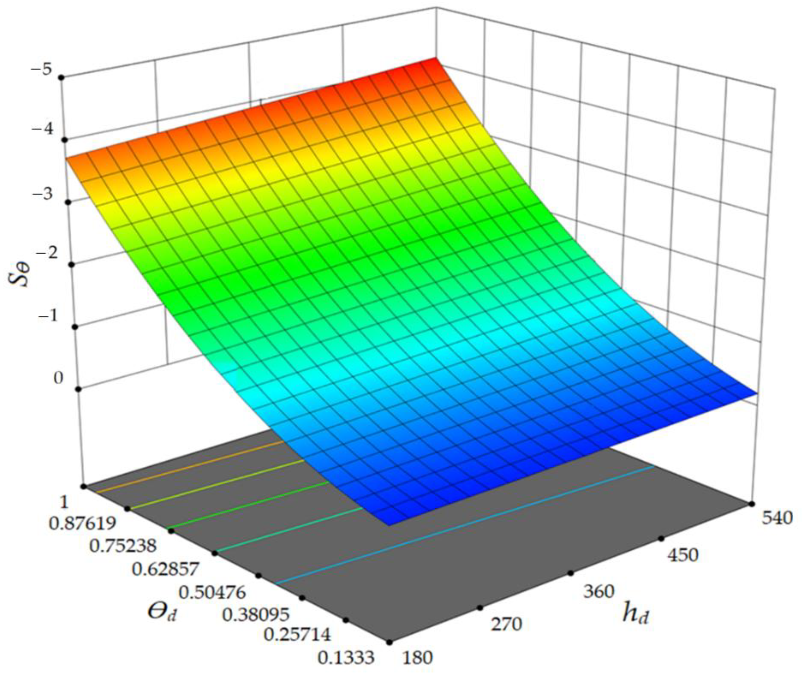
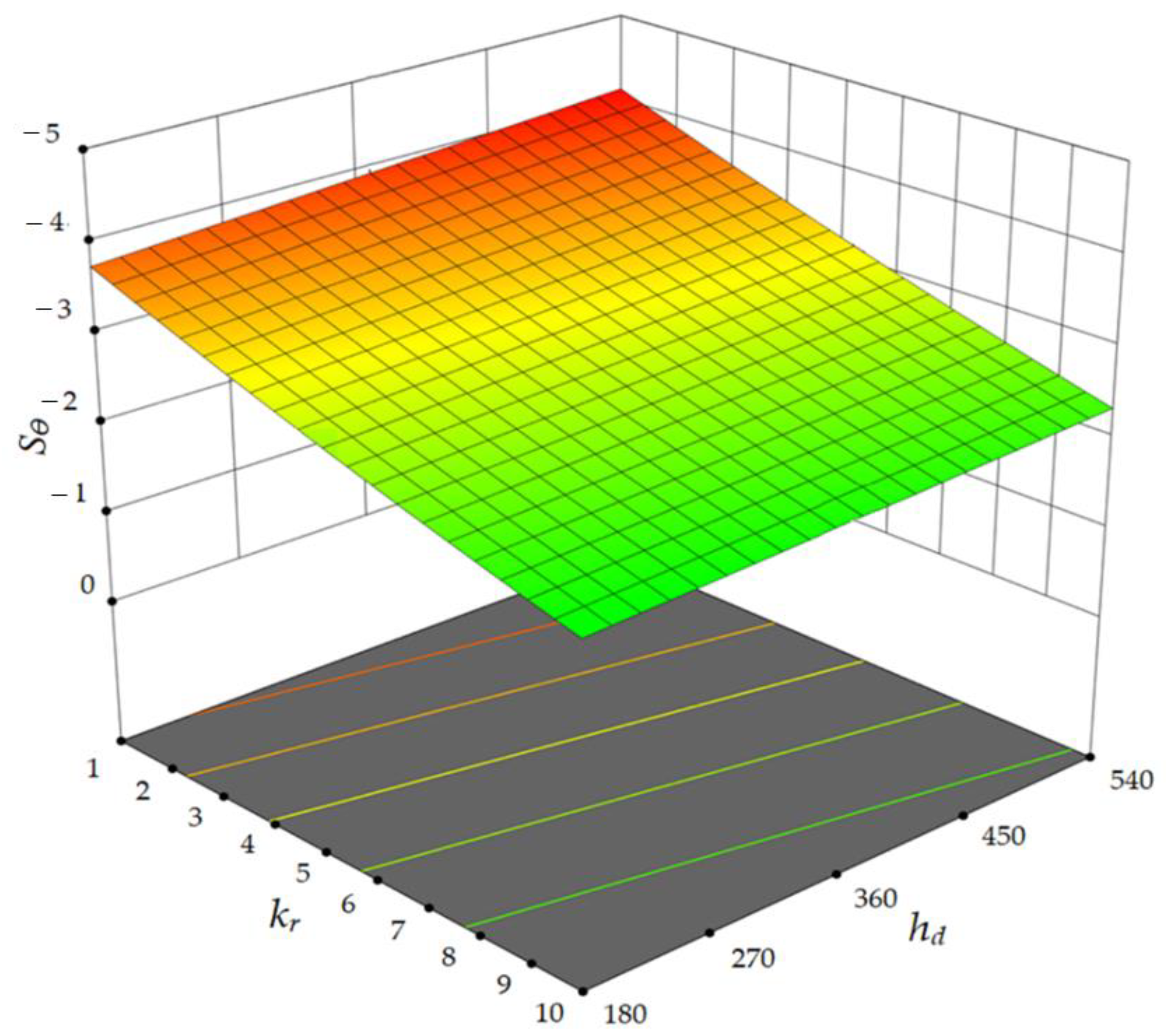
- Numerical investigations clearly indicated the effect of three dimensionless parameters (, θd and kr) on the skin factor due to inclination in the vertical wells. The results demonstrate that the ratio of inclination angle to the maximum inclination angle (75°) and the permeability ratio significantly affect the skin factor and pressure drop in the near-wellbore region. In contrast, the ratio of reservoir thickness to wellbore radius (hd) has a more negligible effect.
- In the case of an inclined open-hole well, the novel correlation presented in the current study simplifies the estimation of the skin factor of inclined wells at different inclination angles. Compared with other approaches, the novel correlation performs well by providing estimates of the skin factor that are relatively close to those of previous models.
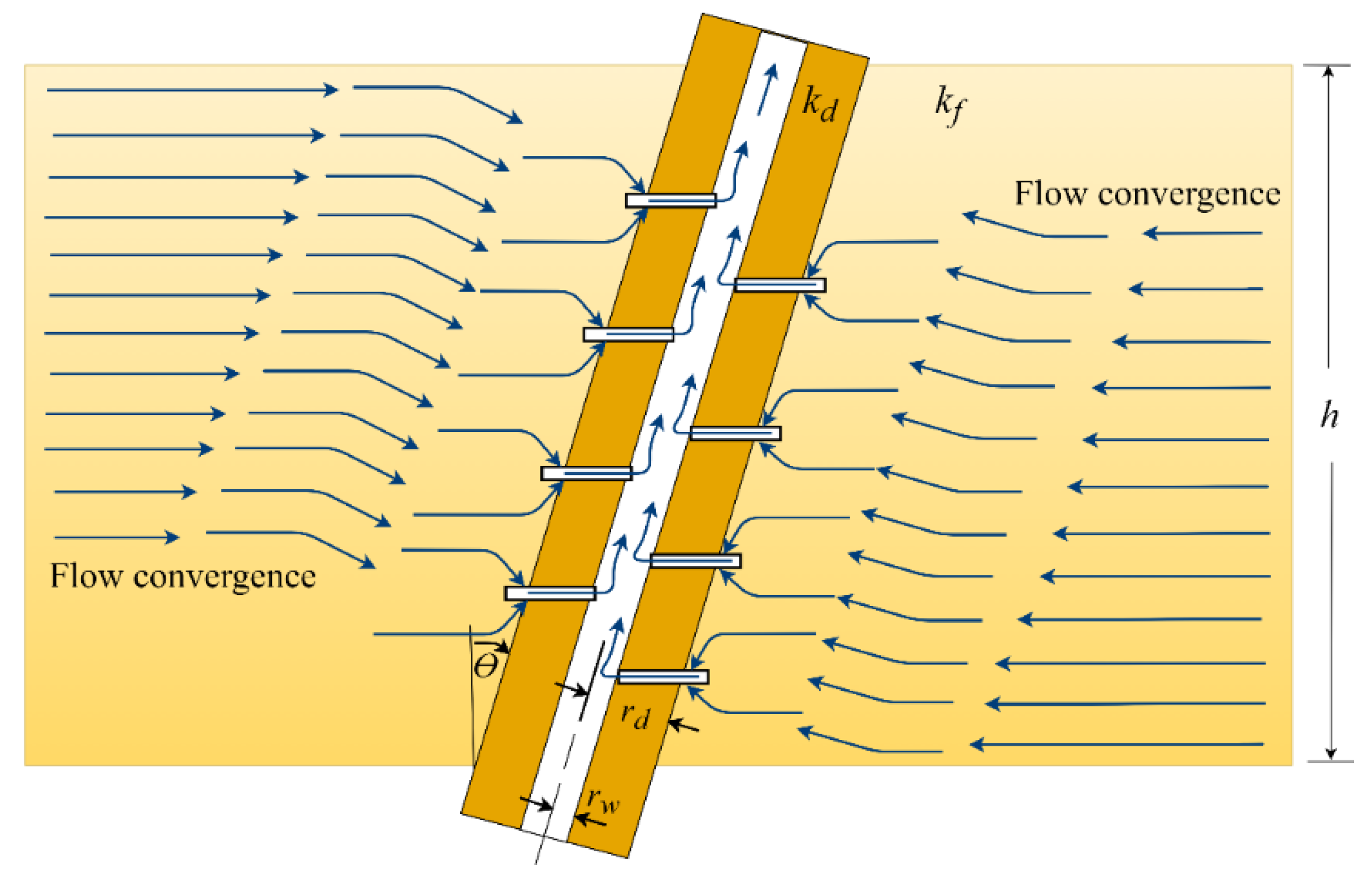
- In the case of an inclined perforated well, the results demonstrate the variance in skin factor and pressure gradient that result from the direction of perforations in relation to the wellbore:
- This difference in the computation of pressure drop and the calculation of the skin factor depends on the complex interaction between several factors, including depth and diameter of perforation, penetration space, perforation angle, and the inclination of the well.
- The difference between the results for the two scenarios indicates that currently available models for evaluating the skin factor of inclined perforated wells need to be improved in light of this variance.
Author Contributions
Funding
Institutional Review Board Statement
Informed Consent Statement
Data Availability Statement
Conflicts of Interest
Abbreviations
| ANOVA | Analysis of variance |
| BBD | Box–Behnken design |
| CFD | Computational fluid dynamics |
| DoE | Design of experiments |
| IPR | Inflow performance relationship |
| PR | Productivity index |
| RSM | Response surface methodology |
| Symbols | |
| ) | |
| Reservoir dimensionless thickness | |
| Ratio of reservoir thickness to wellbore radius | |
| Index of anisotropy | |
| Damage permeability (m2 ) | |
| Horizontal permeability (m2) | |
| Permeability ratio | |
| L | ) |
| ) | |
| ) | |
| np | Number of perforations (number of perforations/foot (30.48 cm)) |
| Flow rate (L/min) | |
| p | Perforation |
| Formation inlet pressure (Pa) | |
| ) | |
| ) | |
| ) | |
| ) | |
| ) | |
| Difference skin factor | |
| Skin factor caused by inclination | |
| See Equation (6) | |
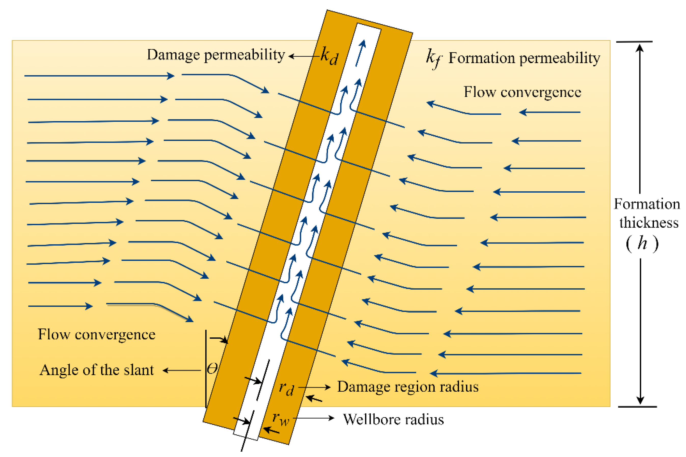
| Angle of the slant | |
| See Equation (3) | |
| Maximum angle of the slant | |
| Ratio of well inclination angle to the maximum inclination angle | |
| ) | |
| Porosity (%) |
References
- Cinco, H.; Miller, F.G.; Ramey, H.J., Jr. Unsteady-state pressure distribution created by a directionally drilled well. J. Pet. Technol. 1975, 27, 1392–1400. [Google Scholar]
- Besson, J. Performance of slanted and horizontal wells on an anisotropic medium. In Proceedings of the European Petroleum Conference, Hague, The Netherlands, 21–24 October 1990. [Google Scholar]
- Rogers, E.J.; Economides, M.J. The skin due to slant of deviated wells in Permeability-Anisotropic reservoirs. In Proceedings of the International Conference on Horizontal Well Technology, Calgary, Alta., Canada, 18–20 November 1996. [Google Scholar]
- Yildiz, T.; Ozkan, E. Pressure-transient analysis for perforated wells. In Proceedings of the SPE Annual Technical Conference and Exhibition, New Orleans, LA, USA, 27–30 September 1998. [Google Scholar]
- Ozkan, E.; Yildiz, T.; Raghavan, R. Pressure-Transient analysis of Perforated slant and horizontal wells. In Proceedings of the SPE Annual Technical Conference and Exhibition, Houston, TX, USA, 3–6 October 1999. [Google Scholar]
- Ozkan, E.; Raghavan, R. A computationally efficient, transient-pressure solution for inclined wells. SPE Reserv. Eval. Eng. 2000, 3, 414–425. [Google Scholar]
- Kyoon, C.S.; Ouyang, L.-B.; Huang, W.S.B. A comprehensive comparative study on analytical pi/ipr correlations. In Proceedings of the SPE Annual Technical Conference and Exhibition, Denver, CO, USA, 21–24 September 2008. [Google Scholar]
- Darcy, H. Les Fontaines Publiques de la Ville de Dijon; Dalmont: Paris, France, 1856. [Google Scholar]
- Wang, H.; Xue, S.; Gao, C.; Tong, X. Inflow performance for highly deviated wells in anisotropic reservoirs. Pet. Explor. Dev. 2012, 39, 239–244. [Google Scholar]
- Ghahri, P.; Jamiolahmady, M. A new, accurate and simple model for calculation of productivity of deviated and highly deviated well–part I: Single-phase incompressible and compressible fluid. Fuel 2012, 97, 24–37. [Google Scholar]
- Feng, G.-q.; Liu, Q.-g. Pressure transient behavior of a slanted well with an impermeable fault. J. Hydrodyn. 2014, 26, 980–985. [Google Scholar]
- Dong, W.; Wang, X.; Wang, J. A new skin factor model for partially penetrated directionally-drilled wells in anisotropic reservoirs. J. Pet. Sci. Eng. 2018, 161, 334–348. [Google Scholar]
- Abobaker, E.; Elsanoose, A.; Khan, F.; Rahman, M.A.; Aborig, A.; Noah, K. Quantifying the partial penetration skin factor for evaluating the completion efficiency of vertical oil wells. J. Pet. Explor. Prod. Technol. 2021, 11, 3031–3043. [Google Scholar]
- Abobaker, E.; Elsanoose, A.; Khan, F.; Rahman, M.A.; Aborig, A.; Butt, S. Comparison of Crushed-zone skin factor for cased and PERFORATED WELLS calculated with and without including a Tip-Crushed Zone effect. Geofluids 2021, 2021, 1–13. [Google Scholar]
- Ahammad, M.; Rahman, M.; Zheng, L.; Alam, J.M.; Butt, S.D. Numerical investigation of Two-phase fluid flow in a perforation tunnel. J. Nat. Gas Sci. Eng. 2018, 55, 606–611. [Google Scholar]
- Ahammad, M.J.; Rahman, M.A.; Butt, S.D.; Alam, J.M. An experimental development to characterise the Flow phenomena at THE Near-Wellbore Region. In Proceedings of the ASME 2019 38th International Conference on Ocean, Offshore and Arctic Engineering, Glasgow, Scotland, UK, 9–14 June 2019. [Google Scholar]
- Rahman, M.A.; Heidrick, T.; Fleck, B.; Koksal, M. Enhancement of the completion efficiency of perforation tunnels in petroleum wells. In Proceedings of the ASME 2006 2nd Joint U.S.-European Fluids Engineering Summer Meeting Collocated With the 14th International Conference on Nuclear Engineering, Miami, FL, USA, 17–20 July 2006. [Google Scholar]
- Rahman, M.A. Scale-up of perforation process from laboratory model to bottom hole dimensions. J. Porous Media 2008, 11, 19–34. [Google Scholar]
- Rahman, M.A.; Mustafiz, S.; Biazar, J.; Koksal, M.; Islam, M.R. Investigation of a novel perforation technique in petroleum wells—Perforation by drilling. J. Frankl. Inst. 2007, 344, 777–789. [Google Scholar]
- Rahman, M.A.; Mustafiz, S.; Koksal, M.; Islam, M.R. Quantifying the skin factor for estimating the completion efficiency of perforation tunnels in petroleum wells. J. Pet. Sci. Eng. 2007, 58, 99–110. [Google Scholar]
- Zheng, L.; Rahman, M.A.; Ahammad, M.J.; Butt, S.D.; Alam, J.M. Experimental and numerical investigation of a novel technique for perforation in petroleum reservoir. In Proceedings of the SPE International Conference and Exhibition on Formation Damage Control, Lafayette, LA, USA, 24–26 February 2016. [Google Scholar]
- Davim, J.P. Design of Experiments in Production Engineering; Springer: Cham, Switzerland, 2016. [Google Scholar]
- Box, G.E.P.; Cox, D.R. An analysis of transformations. J. R. Stat. Soc. Ser. B (Methodol.) 1964, 26, 211–243. [Google Scholar]
- Box, G.E.P.; Behnken, D.W. Some new three level designs for the study of quantitative variables. Technometrics 1960, 2, 455–475. [Google Scholar]
- Ferreira, S.L.C.; Bruns, R.E.; Ferreira, S.H.; Matos, G.D.; David, J.M.; Brandão, G.C.; da Silva, E.G.P.; Portugal, L.A.; dos Reis, P.S.; Souza, A.S.; et al. Box-Behnken design: An alternative for the optimization of analytical methods. Anal. Chim. Acta. 2007, 597, 179–186. [Google Scholar]


| Dimensions and Properties of the Sample | Values (Units) |
|---|---|
| Reservoir or pay zone thickness () | 2.66 m |
| Reservoir radius () | 10 m |
| Formation permeability () | 10−14 m2 |
| Porosity ( | 20% |
| Flow rate ( | 2 L/min |
| Viscosity of water () | 0.00103 kg/(m·s) |
| Perforation depth | 30.48–91.44 cm |
| ) | 1–2.5 cm |
| Penetration space ) | 1–5 perforations/30.48 cm |
| Dimensions and Properties of the Sample | Values (Units) |
|---|---|
| Ratio of reservoir thickness to wellbore radius () | 80–540 |
| Range of permeability ratio () | 1–10 |
| Range angle of the slant () | 10°–75° |
| Runs | ||||
|---|---|---|---|---|
| 1 | 180 | 0.566665 | 10 | −0.35 |
| 2 | 180 | 0.13333 | 5.5 | −0.0010 |
| 3 | 180 | 1 | 5.5 | −2.9 |
| 4 | 360 | 0.13333 | 10 | −0.02 |
| 5 | 180 | 0.566665 | 1 | −1.32 |
| 6 | 360 | 0.13333 | 1 | −0.1 |
| 7 | 360 | 1 | 1 | −4.2 |
| 8 | 360 | 1 | 10 | −2.22 |
| 9 | 540 | 1 | 5.5 | –3.1 |
| 10 | 540 | 0.566665 | 10 | −0.41 |
| 11 | 540 | 0.13333 | 5.5 | −0.06 |
| 12 | 540 | 0.566665 | 1 | −1.8 |
Publisher’s Note: MDPI stays neutral with regard to jurisdictional claims in published maps and institutional affiliations. |
© 2021 by the authors. Licensee MDPI, Basel, Switzerland. This article is an open access article distributed under the terms and conditions of the Creative Commons Attribution (CC BY) license (https://creativecommons.org/licenses/by/4.0/).
Share and Cite
Abobaker, E.; Elsanoose, A.; Khan, F.; Rahman, M.A.; Aborig, A.; Noah, K. A New Evaluation of Skin Factor in Inclined Wells with Anisotropic Permeability. Energies 2021, 14, 5585. https://doi.org/10.3390/en14175585
Abobaker E, Elsanoose A, Khan F, Rahman MA, Aborig A, Noah K. A New Evaluation of Skin Factor in Inclined Wells with Anisotropic Permeability. Energies. 2021; 14(17):5585. https://doi.org/10.3390/en14175585
Chicago/Turabian StyleAbobaker, Ekhwaiter, Abadelhalim Elsanoose, Faisal Khan, Mohammad Azizur Rahman, Amer Aborig, and Khalid Noah. 2021. "A New Evaluation of Skin Factor in Inclined Wells with Anisotropic Permeability" Energies 14, no. 17: 5585. https://doi.org/10.3390/en14175585
APA StyleAbobaker, E., Elsanoose, A., Khan, F., Rahman, M. A., Aborig, A., & Noah, K. (2021). A New Evaluation of Skin Factor in Inclined Wells with Anisotropic Permeability. Energies, 14(17), 5585. https://doi.org/10.3390/en14175585