1. Introduction
One of the ways to reduce environmental pollution is to use alternative fuels to drive internal combustion engines. The most advantageous solution is the application of renewable fuel. The use of alternative, renewable fuel will allow for the diversification of fossil fuels and their replacement in the future. The use of alternative, renewable fuels also allows an increase in the efficiency of conversion of chemical energy into mechanical work. The most common (alternative) gaseous fuels are CNG and LPG (compressed natural gas and liquid petroleum gas) in Europe, and in Asia, DME (dimethyl ether) is also used on a large scale.
The research carried out so far has allowed assessing the possibility of using gaseous fuels to power internal combustion engines. The most common gaseous fuels (LPG and CNG) have a standardized composition, and their use in modern combustion engines with digital control systems for their operation allows for their effective use [
1,
2,
3,
4]. The number of cars using multifuel systems is constantly growing. However, the challenge is still to design a system that allows for an efficient power supply to motors, both in terms of their economy and efficiency of energy conversion. The problem of the efficiency of the combustion process has been discussed in previous studies [
5,
6,
7,
8]; in particular, it concerns the speed of flame spread and high temperature during the combustion process.
The literature also includes studies describing the possibility of using mixtures of gaseous fuels. Zareei [
9] developed a numerical analysis of the combustion process in a diesel engine fueled with natural gas (CNG), and a mixture of natural gas and hydrogen (HCNG) was carried out. During the analysis, the ignition advance angle was corrected, which resulted in an increase in engine efficiency. In another article [
10], the process of natural gas combustion with a hydrogen addition was observed. The addition of hydrogen led to an improvement in the dynamic parameters of the engine, its economy and improved emissivity.
The current state of knowledge also allows finding items describing the use of LPG and DME mixtures. In the work by Nakazono [
11], the possibility of using a LPG–DME mixture was presented. It was pointed out that DME has physical and chemical properties similar to LPG fuel. Moreover, the results confirming the possibility of limiting the occurrence of knocking combustion by an appropriate adjustment of the ignition advance angle were also presented. The work of Chen et al. [
12] allowed determining the maximum share of DME in the mixture. The DME share should not exceed 40%. Above this value, the engine output parameters are significantly reduced. The publication by Seokhawn Lee [
13] presented the results of using n-butane and DME to power an internal combustion engine. Particular attention was paid to the problems of exhaust emissions and engine dynamics. Stable operating was observed in a wide range of loads and rotational speeds of the engine. In addition, it was noticed that the engine output parameters, fuel consumption and emissions were similar to the results obtained for the pure LPG engine.
During what was written before, direct DME production began in the 1990s in Asia and North America.
DME as a fuel is most often used in Asia (Japan and China and, to a lesser extent, India); the United States of America and the Middle East (Iran) [
14,
15,
16]. In these parts of the world, DME is used as a pure energy carrier or as an additive to LPG. Submitting a detailed analysis of the possibility of using DME as an energy carrier, one cannot pay attention to the possibility of obtaining this fuel from renewable sources. The current international policy is aimed at obtaining energy from zero-emission or, at most, low-emission sources. DME can be obtained from both low and zero-emission sources. The possibility of obtaining DME from a biomass seems to be particularly interesting. The energy obtained in this way is called BioDME. However, the process of obtaining DME from plastic waste is also of interest.
1.1. Sourcing DME from Plastic Waste
DME is most often obtained by syngas synthesis. Syngas is produced by gasifying plastic waste. This process is carried out in two ways: indirect and direct, and both methods use for it gasifiers. The harmfulness of plastic waste and its negative impact on the environment is obvious. Therefore, it seems right to find a method of managing plastic waste, which enables its process into DME.
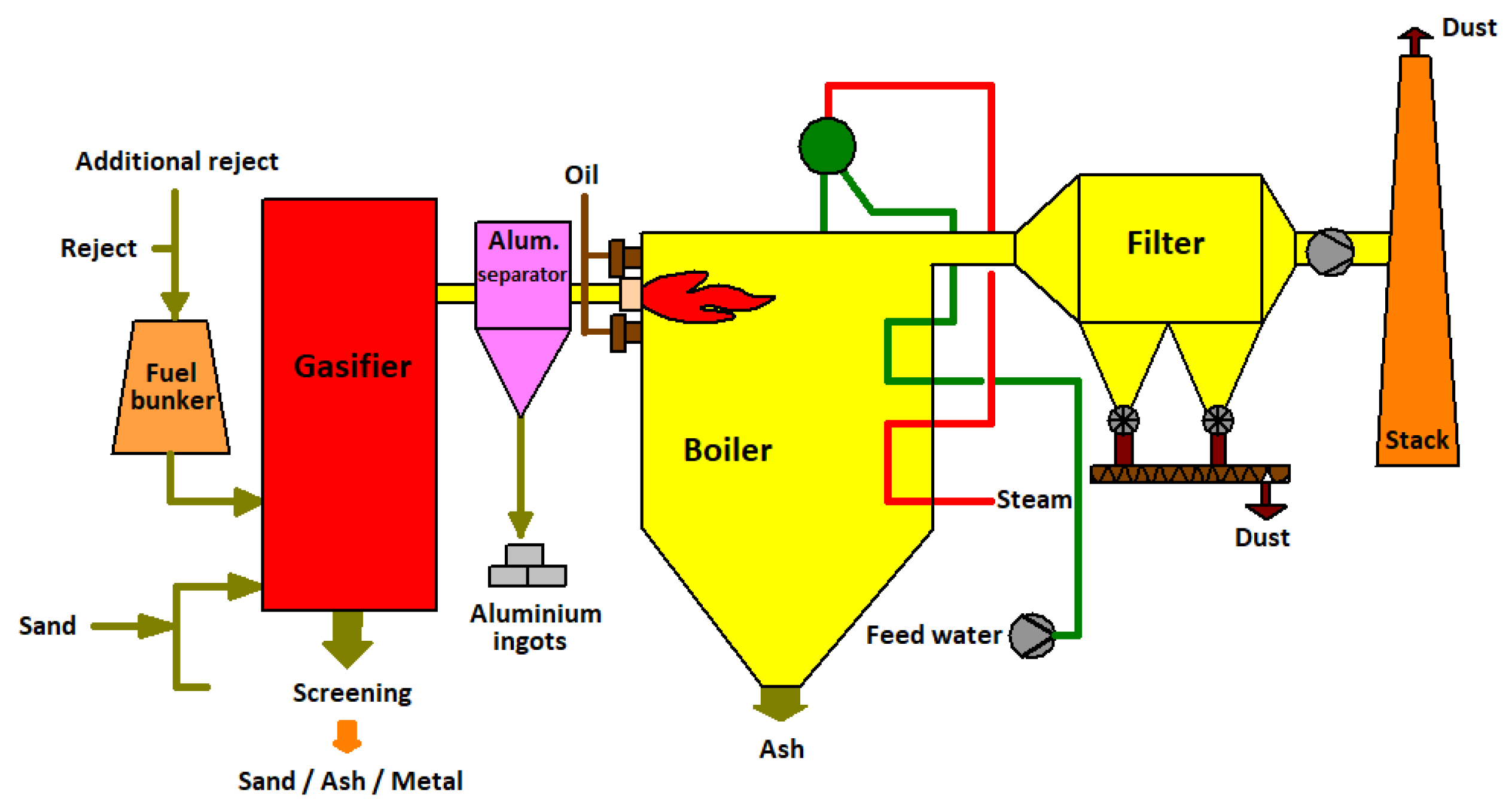
The developed, latest method of the gasification of plastic waste allows the elimination of heavy metals and dioxins. This process was initially developed for the chemical industry; now, it is possible to use this technology to produce fuel while reducing landfills with plastic waste. An example of a plastic gasification process used in Finland is shown in
Figure 1 [
17].
The waste gasification method proposed by Corenso United Ltd. is based on a two-stage treatment process. In the initial stage of the process, the plastics are ground and pressed under high pressure in a nitrogen atmosphere. Then, the charge prepared in this way is directed to the low temperature part of the gasifier. The temperature in this part of the process is 600–800 °C. It is in this part of the process that heavy metals are eliminated through removal with the lower part of the gasifier. After the low temperature part, the charge is directed to the high temperature part (1300–1500 °C), where syngas is produced in the chamber.
The presented two-stage process of obtaining syngas also has a significant advantage in the form of the possibility of processing unsorted plastic waste. In addition, metal elements such as aluminum, copper and iron are recovered during the gasification process.
1.2. Syngas Synthesis and DME Received
The syngas obtained in the process of the gasification of plastic waste is subjected to a synthesis process to obtain DME. This process may take the form of an indirect method, where syngas is converted into methanol and, in the next stage, DME, and a direct method, in which DME is obtained from the synthesis and dehydration process; they are performed simultaneously in the same reactor chamber.
The indirect method is described by the following chemical equations:
The last level of the reaction is possible by carrying out the reaction in the presence of a copper catalyst.
The second stage of the reaction makes it possible to obtain DME from the dehydration process:
The compatibility of the process of indirect syngas synthesis and obtaining DME makes it possible to implement this in the industry. The current state of advancement of synthesis processes in the industry allows the direct use of this method and the introduction of a new fuel to the market.
The use of direct synthesis is currently not widespread. The processes used in the industry most often lead to the acquisition of methanol in the next stage to obtain DME. The direct method requires a high temperature and pressure, which complicates the apparatus and, at the same time, covers the costs of obtaining DME. The chemical reaction of the direct syngas synthesis process is shown below:
A high DME extraction efficiency is only possible if H
2/CO is equal to 2/1, and the CO
2 conversion efficiency is not less than 90%. In such a situation, the chemical reaction can be written as follows:
The equilibrium of the CO conversion is higher when the synthesis of methanol and pure DME can be obtained without H
2O. This is the most important feature of the direct process [
18,
19].
2. DME Application for Combustion Engines
Currently, the electrification of the drive systems of motor vehicles is being developed extensively. This move is understandable due to the reduction of CO2 emissions into the world’s atmosphere. It is believed that nearly 10 carbon dioxide emissions are caused by road transport. However, the transformation process to complete zero-emission propulsion is lengthy and may take several months or several years. This period can be used to use alternative fuels to power internal combustion engines. From the point of view of CO2 emissions, the most advantageous would be to use renewable fuels, including DME and BioDME produced from a biomass and plastic waste.
The most commonly used fuels for supplying internal combustion engines are primarily mixtures of hydrocarbons. Both liquid and gaseous fuels are used.
Table 1 presents the characteristic physicochemical parameters of the fuels that are most often used in various regions of the world.
The world’s public opinion has drawn attention to the problem of the huge and growing pollution of plastic waste. Therefore, it becomes necessary to implement a technology enabling the processing of this waste. One way is to use the waste to produce DME (previously described). Since the properties of DME confirm the suitability of this substance as an engine fuel, it will be possible to use it for powering motor vehicles.
2.1. Other Renewable Fuels for IC Engines
The current tendency to reduce CO
2 emissions in the atmosphere has caused a search for other energy sources to power internal combustion engines. One way is to use renewable fuels based on plant esters. Fuel derived from vegetable esters can be used in RCCI engines. One such fuels is oil derived from thevetia peruviana [
20,
21], which is administered as a supplement to the main dose of diesel fuel. The use of this fuel allows reducing NO
x emissions and smoke. The greater the decrease in these factors, the higher the share of ester in the main fuel dose. The disadvantage of this fuel is the increase in hydrocarbon emissions.
Previous publications [
22,
23] presented a proposal to use castor oil (RCM20) as an additive to diesel fuel. The use of this fuel resulted in an increase in the indicated pressure by approx. 9.5%, and a reduction in CO, HC and CO
2 emissions was achieved by 47.6%, 26.8% and 34.9%, respectively. During the measurements, an increase in NOx emissions was noticed, which indicates the need to search for the optimal settings of the EGR system.
2.2. DME for CI Engines
Due to the relatively high cetane number, DME will be the most effective fuel for diesel engines. A cetane number within the range of 55–60 results in a much more favorable energy conversion in this type of engine. At the same time, the ease of evaporation and the high speed of mixing with the air will result in the formation of more homogeneous mixtures. A more homogeneous mixture in a diesel engine will lead to an increase in the culture of engine operation (lower noise and vibrations) and reduce the emission of mainly solid particles.
An important issue is the equipment that allows fuel to be fed directly into the combustion chamber. Due to the nature of diesel engine operation, DME fuel should be injected into the cylinder in the liquid phase. At the same time, an important issue is the precision of fuel dosing, which can only be achieved using a microprocessor-controlled system. Such a system will enable the introduction of a precisely measured amount of fuel into the engine depending on its load and rotational speed. Currently, such assumptions are met only by the Common Rail system.
Similar to the diesel engines used in CR systems, DME must be compressed in a pressure accumulator. Obtaining high-pressure DME in a tank is possible by using a high-pressure pump. The executive elements that allow the introduction of fuel into the combustion chamber are electrohydraulic injectors with a construction similar to those of the classic CR system. Due to the low lubricating properties of DME, the injectors and the high-pressure pump must have a structure that improves the tribological properties. The proposed solutions improving the structures of these elements in terms of tribology use Teflon (PTFE) inserts or the application of DLC (diamond-like carbon) layers. The use of these methods reduces the friction in the elements of the injector and a high-pressure pump.
The use of chemical methods (PTFE or DLC) significantly complicates the production process of these elements and increases the costs at the same time. A solution may be to use a mixture of DME fuel and diesel fuel. A small amount of diesel oil allows for increasing the lubricating properties of the fuel, which is very important for the precise injection equipment of a diesel engine. The disadvantage of this solution is the reduction of the ecological aspect of using DME to power diesel engines.
The use of DME entails the problem of the formation of vapor locks in the supply system (fuel lines and fuel filter), which is related to the low boiling point. This problem was solved by using a compressor that is part of the high-pressure pump. The role of the compressor is to reliquefy the DME and introduce it in the liquid phase to the supply system (
Figure 2).
DME is delivered into the cylinder in the evaporated phase under the same high pressure as the diesel fuel. This system used doubled injectors, one for diesel fuel and the second for DME. The use of dual-fuel power entails the need to solve the problem of different speeds of mixing fuel with air. Diesel fuel takes a much longer time to evaporate and mix with air, while, in the case of DME, its low boiling point causes it to mix with air much faster, creating a more homogeneous mixture [
12,
13].
Volvo, as one of the European producers, has proposed a kind of truck (heavy-duty over 12 tons) powered by DME (
Figure 3) to be used in Europe and the USA [
20].
Many world research projects on DME usage are being carried out in Asia, especially in Japan, China and South Korea. This is due to the large amount of DME produced there.
Projects in Japan are being designed not only to develop engine power supply systems but, also, to develop a full fuel distribution infrastructure. This is important when starting to distribute new fuel on the market.
The use of DME as a fuel for diesel engines allows reducing the emissions of toxic compounds into the environment. The reduction of the negative environmental impact is partially possible, because the physicochemical properties of dimethyl ether predispose this fuel to better mix with air. However, limiting the negative impact on the environment is possible only in certain ranges of engine operations.
Figure 4,
Figure 5 and
Figure 6 show the measured CO, HC and NO
x emissions for a diesel vehicle and DME for four engine speeds: 1200, 1500, 1800 and 2000 min
−1.
The above charts clearly show that a relatively low emission of toxic components is possible at low engine loads. On the other hand, as DME load fed into the engine increases, the emissions also increase. This indicates the need for further research into the reduction of emissions of CI engines powered by DME.
Feeding CI engines with dimethyl ether also gains a reduction in combustion noise. The pressure increase in the cylinder is much lower than that of diesel fuel. A quick mixing of DME with air and a greater self-ignition tendency increase the start of the combustion process. Changing the slope of the cylinder pressure build-up curve leads to engine noise reduction. DME shows low harmfulness to the environment as soon as it enters the atmosphere. It does not enlarge the ozone hole and, therefore, is not affected by global warming. This important factor should also take into account the possibility of introducing DME as a fully-fledged ecological fuel, enabling the supply of compression-ignition engines.
2.3. SI Engines Feeded DME and LPG Mixtures
The boiling point of DME is similar to LPG, which enables the creation of DME–LPG mixtures used in households. Such a mixture enables the supply of heat pumps and generators. Based on the analysis of the characteristic parameters, it can be assumed that LPG–DME mixtures can be energy carriers diversifying LPG. This will reduce the consumption of fossil fuels and increase the energy security.
DME has a low-octane value (
Table 1), and therefore, it cannot be used as a clean fuel to power an SI engine. The easy mixing of LPG and DME was used during the tests of a stationary SI engine designed for a micro-cogeneration system and propelled by LPG and DME mixtures with DME mass shares of 5–40% [
16]. These studies allowed for the development of combustion control algorithms primarily based on the signals of a standard knock sensor and ionization current control.
Similar to hydrogen with natural gas (HCNG), the addition of DME to LPG could be an activator of the combustion process in SI engines. The use of DME may also contribute to the reduction of CO
2 emissions by vehicles powered by a mixture of LPG and DME. A higher hydrogen and DME combustion velocity accelerates the process of combustion initiation in the case of both natural gas and LPG, which are nowadays widely used in motor vehicles (
Figure 7).
In the case of SI engines, it is necessary to use infrastructure adapted for the storage and distribution of DME. As mentioned in previous articles, DME has similar properties to LPG; it is therefore possible to use the existing solutions of the LPG feed system to power engines of a LPG–DME mixture. Only one thing will be changed in the apparatus sealant materials. In the case of DME, there is an intensive process of penetration deep into the sealant that results in the phenomenon of increasing the volume of the sealing elements. Increasing the volume of the sealant materials may lead to dysfunction of the systems responsible for the fuel flow (especially for electro valves).
The use of DME as an additive enriching LPG makes it necessary to consider the moment of introducing the admixture. At the present stage, DME can be added to LPG at the bottling plant, where it is possible to introduce an appropriate amount of the admixture. It is also possible to mix DME with LPG at the refueling station just before filling the fuel tank in the vehicle. Both methods still require analyses in terms of the profitability and technical possibilities. The aforementioned diversification of LPG fuel forces the introduction of additional systems enabling the process of creating LPG–DME mixtures. A preliminary design of such a stand was made at the Faculty of Transport and Aviation Engineering of the Silesian University of Technology. The installation diagram is shown in
Figure 8.
Using the presented stand, tests have been carried out on the impact of DME admixtures on the dynamic parameters of an engine. During this research, it was possible to assess the efficiency of LPG and DME fuel mixture combustion.
The main goal of this study was to verify the possibility of fueling an SI engine with a LPG–DME mixture. This assessment was to verify the stability of the engine operation and to determine the effect of the DME additive on the indicators of the combustion process in a cylinder (imep, dp/dα and maximum pressure). This will allow for the formulation of our final conclusions about the suitability of this type of fuel to power an SI engine.
It was possible to carry out a specific test program with the use of a stand that enables the creation of fuel mixtures. The stand enables the preparation of LPG–DME fuel mixtures thanks to the flow regulation system and precise strain gauge balance. The stand (
Figure 8) enables the preparation of fuel mixtures with the following proportions:
The research vehicle was equipped with a gaseous fuel supply system, enabling it to be fed and driven with the prepared mixture. The prepared power supply system changed the state of the fuel aggregation (liquefied to vaporized) and allowed for the introduction of a measured dose into the combustion chamber of the engine. The adopted test program allowed for the assessment of the combustion process and its consequences for three different RPM of the engine: 2000, 2500 and 3000 min−1.
3. Research Objects and Measurements Set-Up
The object of the research was a 1600-cm
3 SI engine installed in an OPEL ASTRA (OPEL Gmbh, Rüsselheim, Germany) car powered by alternative gas fuels. The main data characterizing the engine are presented in
Table 2.
The engine operating parameters were determined by analyzing its characteristics with a Bosch FLA 203 (Robert Bosch, Gerlingen, Germany) chassis dynamometer for previously prepared mixtures with different mass fractions of DME.
The test stand was equipped with transducers and sensors ensuring the identification of the engine operating state. The basic control and measurement systems, ensuring continuous recording of the engine operation status, were:
Pressure inside of the 4th cylinder,
Crankshaft RPM,
TDC of the 4th cylinder,
Power on the wheel,
Intake manifold pressure,
Gas exhaust temperature and
Gaseous fuel mass flow delivered to the engine.
Imaging of the pressure changes in the cylinder was carried out using the KISTLER 6121 (KISTLER, Winterthur, Switzerland) transducer connected to the KISTLER 5011 (KISTLER, Winterthur, Switzerland) charge amplifier. The engine’s indication capability was supplemented by the need to precisely measure the speed and the position of the crankshaft. The implementation of this task was possible thanks to the system based on the KISTLER 2613B (KISTLER, Winterthur, Switzerland) tag embedded in the engine’s crank pulley. The measuring system was supplemented with the registration of the pressure in the intake manifold using a standard sensor, which is the equipment of the basic power supply system.
The weight of the gaseous fuel consumed was measured using a precise strain gauge. All the measurement signals were recorded by the National Instruments PCI-6143 (National Instruments, Austin Texas) data acquisition card in the proprietary software environment developed in LabView (National Instruments, Austin Texas). A simplified diagram of the test stand is shown in
Figure 9.
4. Results and Discussion
The potential for DME–LPG mixture implementation as SI engine fuels was determined on the basis of the in-cylinder pressure course analysis. The pressure was measured as a function of the engine stroke (close indicator diagram).
The method ensuring the stable operation of the engine consisted of an analysis of the pressure courses in the cylinder and their basis as the preliminary assessment of the quality of the engine’s working cycle. The analysis of the pressure in the cylinder was carried out in real time, which allowed for the optimization of the adjustment parameters of the engine.
The DME share in the mixture, together with the engine speed, were defined as the variables.
Figure 10 shows the courses of the close indicator charts. For the developed diagrams of the average in-cylinder pressures, the value of the indicated mean effective pressure (imep) was determined by using the arithmetic mean according to the formula:
where
N—number of cycles.
Changes in the indicated mean effective pressure for the different DME shares of the fuel used in the tested engine are shown in
Figure 11.
The analysis of the indicated mean effective pressure value leads to the conclusion that the maximum imep values for all the engine speeds were achieved for the mixtures containing 11% and 14% DME. The gaseous fuel with the presented DME shares is characterized by higher values of the indicated pressure, even in relation to the reference LPG fuel.
The analysis of the maximum in-cylinder pressure values demonstrates a tendency to change the angular position of the maximum pressure value, depending on the DME share in the LPG–DME mixture.
Figure 12 shows the changes in the angle of occurrence of the maximum pressure.
Regardless of the engine speed, the value of the maximum pressure is displaced in relation to the TDC. This displacement, however, is not even. In the case of the 7% DME share, there was a significant acceleration of the moment of the maximum pressure value. Starting from the DME shares of 11% and 14%, there was a visible tendency to delay the occurrence of the pressure maximum value. With 17% and 21% DME, there can be noticed an acceleration in the occurrence of the maximum cylinder pressure, and for 26% DME, the moment of maximum pressure occurrence was significantly delayed. The share of 30% DME was characterized by the acceleration of the angle of occurrence of the maximum pressure. The mixtures featuring DME shares of 11%, 14%, 26% and 30% resulted in a similar maximum pressure angle as the reference fuel (LPG). The remaining LPG–DME mixtures had angles of the maximum pressure that significantly differed from the values achieved for LPG.
The explanation for this tendency should be sought in the course of the fuel combustion process in the cylinder. One of the parameters characterizing the course of the combustion process is the engine hardness. For the determined pressure courses in the cylinder, the
dp/dα parameter was calculated.
Figure 13 shows the determined hardness courses for the different DME shares.
As in the case of the pressure diagrams in the cylinder, clear differences in the
dp/dα waveforms also appeared in the case of the engine hardness analysis. In
Figure 14, the maximum hardness values for the tested fuels are shown.
The changes in the values of engine hardness were more or less even, especially for the DME shares from 7% to 26%. A significant increase in the hardness could be observed for the 30% DME share in the fuel mixture. This means that, when one-third of the fuel mass is replaced by a component with radically different properties influencing the combustion process, it causes a rapid increase in the engine hardness. However, it can be observed that the LPG–DME fuel has a lower hardness than the reference LPG fuel.
The overall efficiency is a parameter that clearly determines the possibility of using LPG–DME fuel in diesel engines. The general efficiency combines all the factors defined by the literature (indicated, technical, mechanical, etc.). At the same time, the overall efficiency describes the quality of the conversion of chemical energy into mechanical work in an internal combustion engine. For the obtained test results, calculations of the general efficiency were carried out, and the results are presented in
Figure 15.
The overall efficiency of the reference fuel (LPG) was the highest; however, for the LPG–DME mixtures, the highest efficiency values were obtained for the shares of 11–17%. The highest efficiency for the LPG–DME mixture was shown with the proportion of 30% DME. However, for fuel containing 30% DME, knocking combustion occurs quite often, which consequently eliminates the possibility of using this mixture for SI engines.
During the research, the temperatures of the exhaust gases were also measured. The results of these measurements are shown in
Figure 16. The exhaust gas temperatures for the LPG–DME mixtures were compared to the temperatures obtained for the base fuel. The base fuel (LPG) exhaust gas temperatures for the three rotational speeds were: 573 °C, 581 °C and 612 °C (suitable for 2000 min
−1, 2500 min
−1 and 3000 min
−1). For the mixtures with DME contents from 17% to 30%, the temperatures were higher than for the reference fuel (583–624 °C at 2000 min
−1, 616–675 °C at 2500 min
−1 and 621–681 °C at 3000 min
−1), comparable to the LPG temperatures recorded with DME shares in the range of 7–14%.
5. Conclusions
The conducted analysis of the possibility of DME applications in SI engines led to the following conclusions:
It is possible to regulate the course of the combustion process by changing the mass fraction of DME in mixtures with LPG as a function of the engine speed.
The calculated values of the indicated pressures showed that the most effective blend was the mixtures containing 11–17% DME.
Based on the results of the bench tests, it can be determined that the most useful shares seemed to be DME–LPG mixtures containing 11–17% DME featuring the lowest dp/dα.
In the case of the exhaust gas temperature analysis, the segregated share ranges (based on the dp/dα engine hardness analysis) confirmed that the lowest thermal loads were recorded for the 7–14% DME shares.
It seems advisable to continue the research into the scope of determining both the optimal control parameters of engines and determining the appropriate values of the air/fuel excess ratio of the LPG–DME mixtures. The purposefulness of further research is all the more necessary as it is possible to use the technology of obtaining DME from plastic waste disposal.
Further work on the possibility of using DME to power SI combustion engines should be directed toward supplementing the knowledge in this field with determining the optimal AFR and determining the impact of an AFR change on the combustion process. An important issue is also determining the emissions of toxic compounds, especially in relation to their current exhaust gas purity standards (EURO6). This will allow not only comparing the combustion processes of fuels with the participation of DME in the reference fuel but will also determine possible actions to reduce the emissions of individual exhaust components.


