
Effect of NACA0012 Airfoil Pitching Oscillation on Flow Past a Cylinder


Abstract
:1. Introduction
2. Verification of Physical Model and Numerical Method
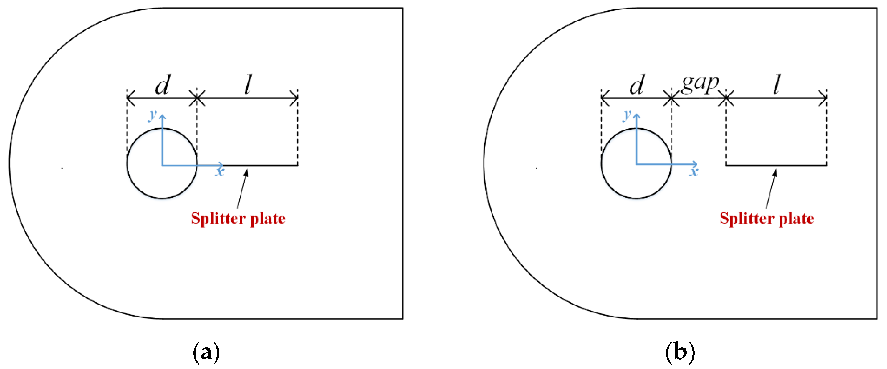
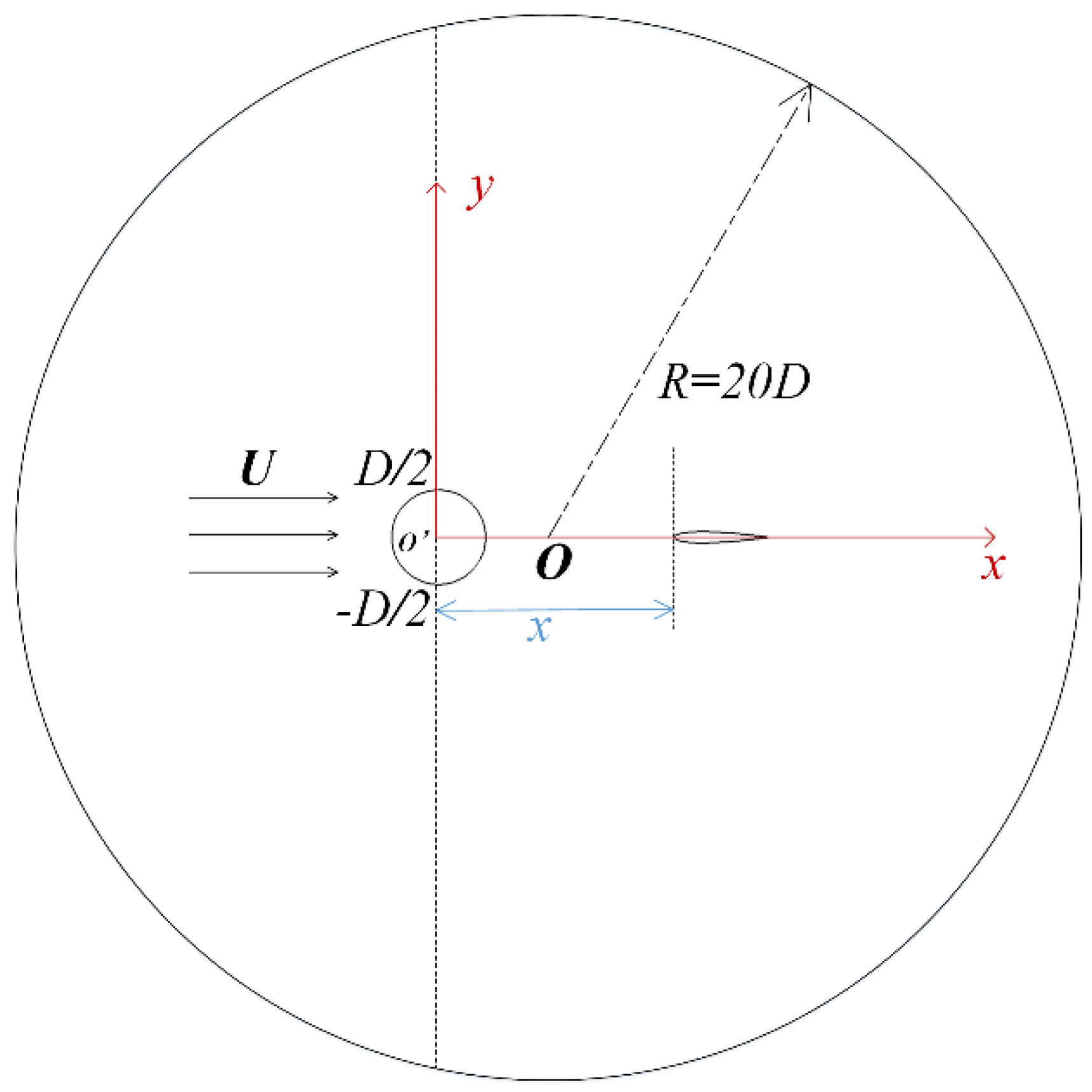
2.1. Physical Model
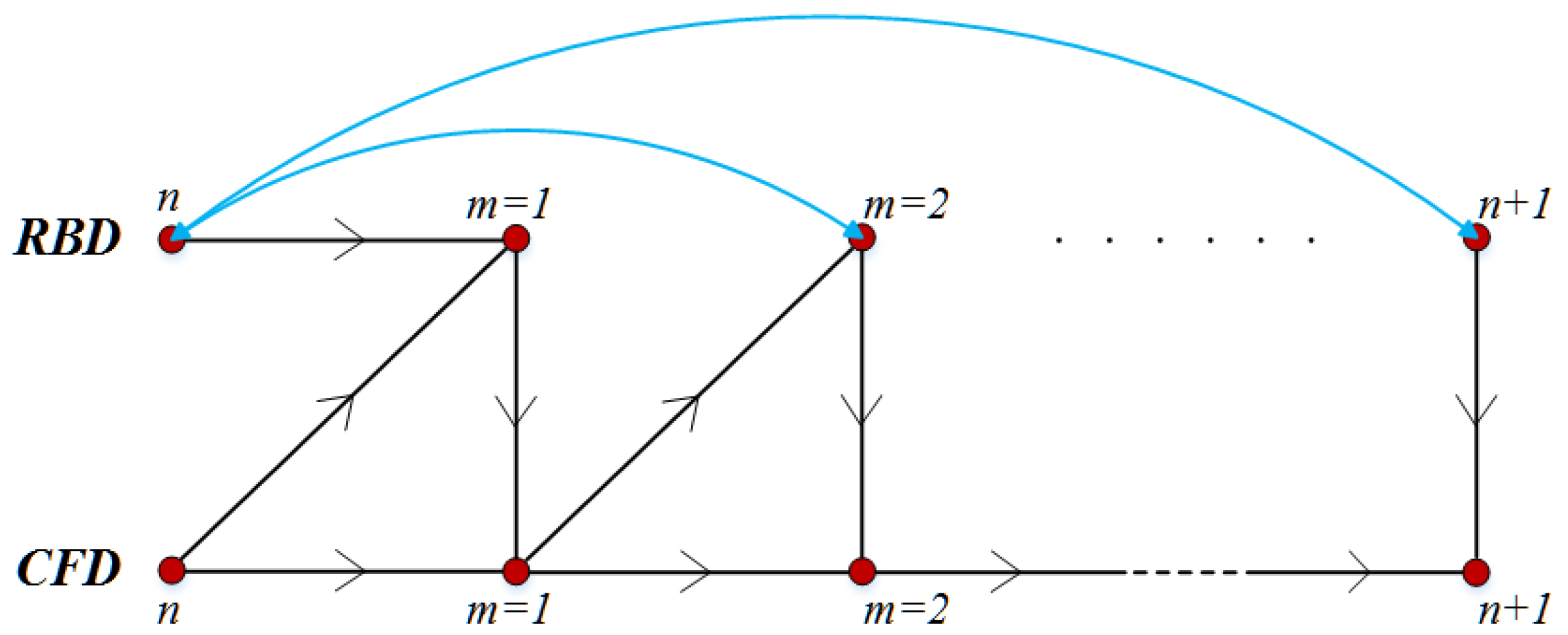
2.2. Numerical Methods
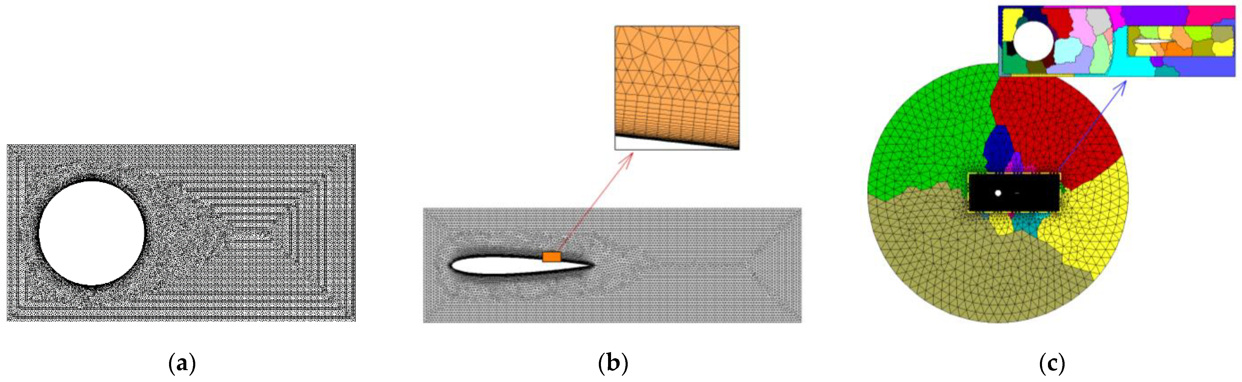
2.3. Mesh Generation
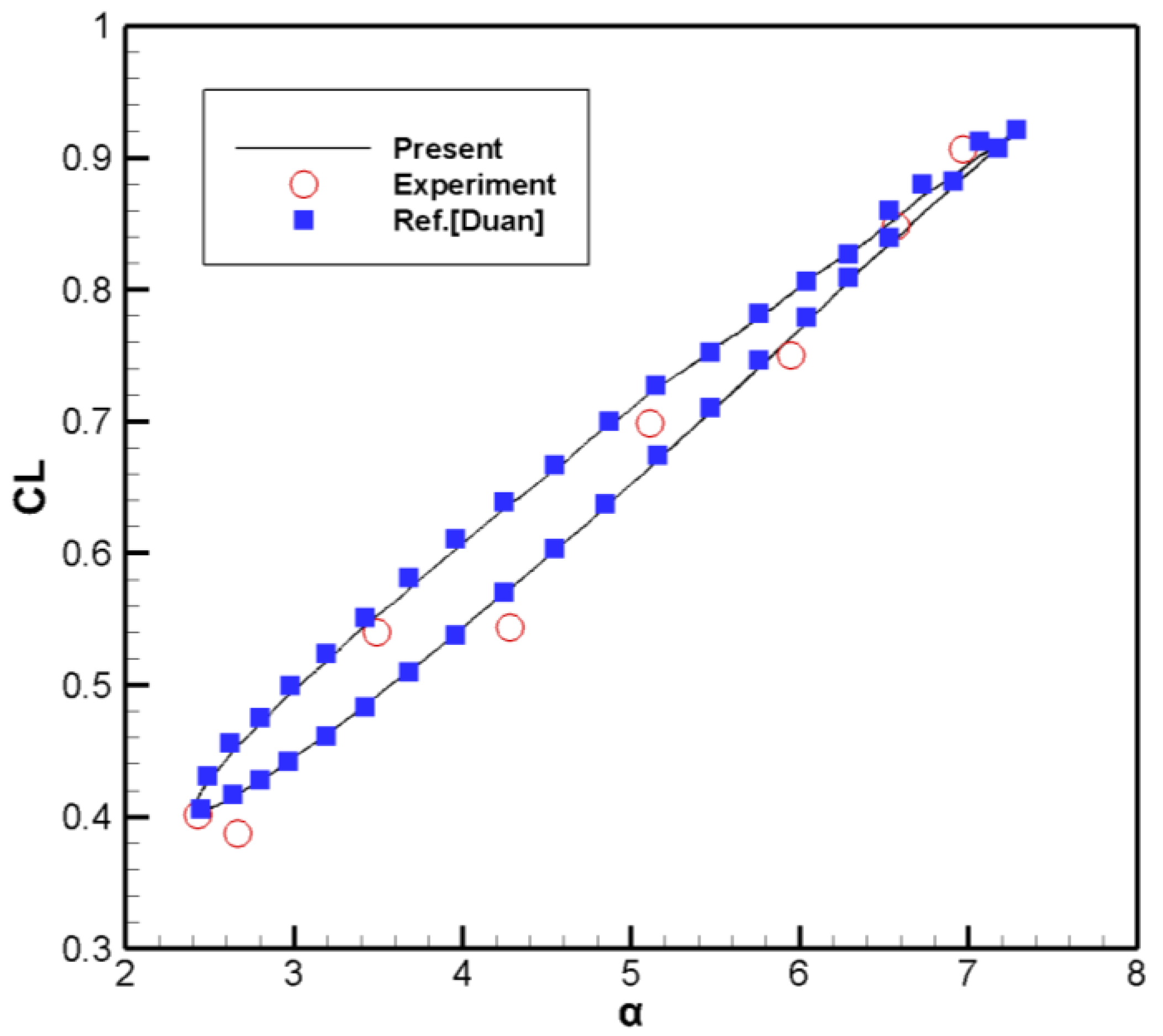
2.4. Verification of Numerical Method
3. Results
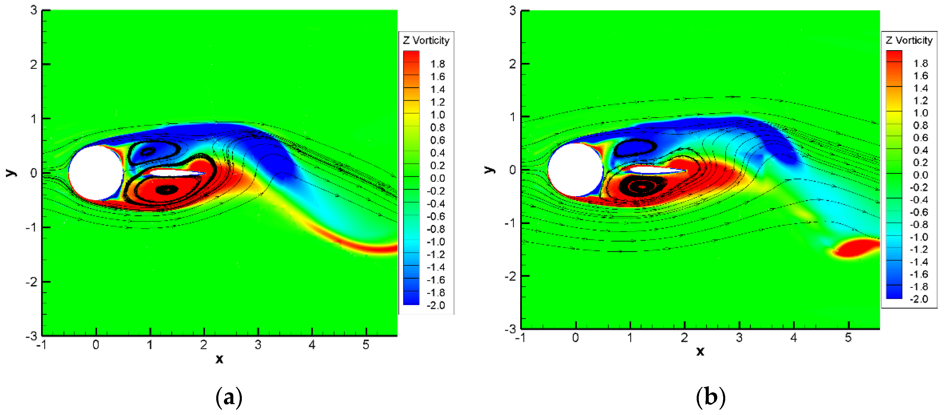
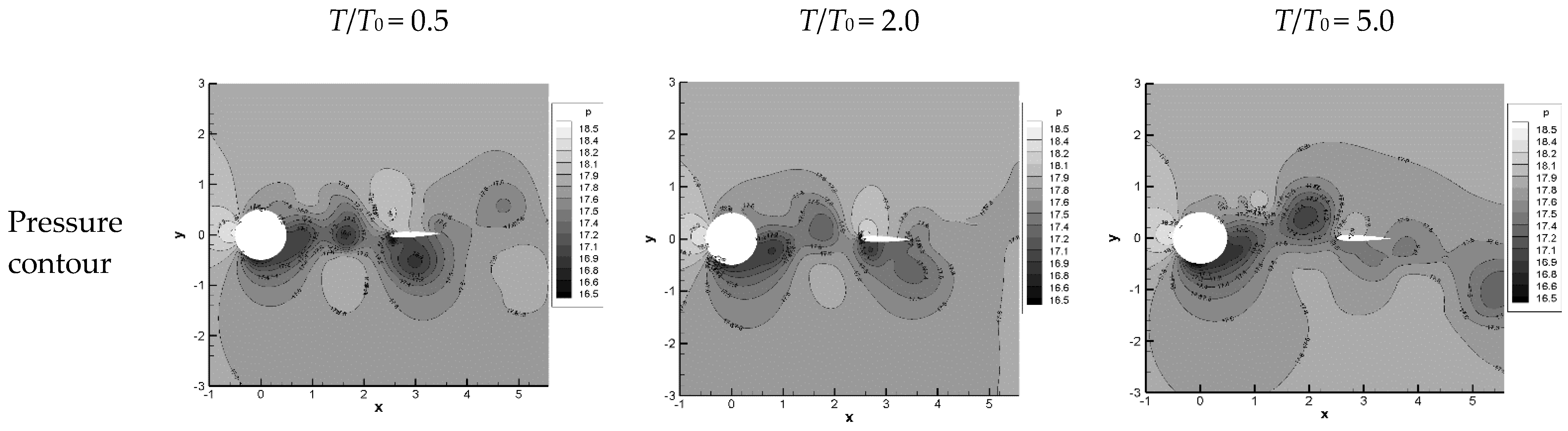
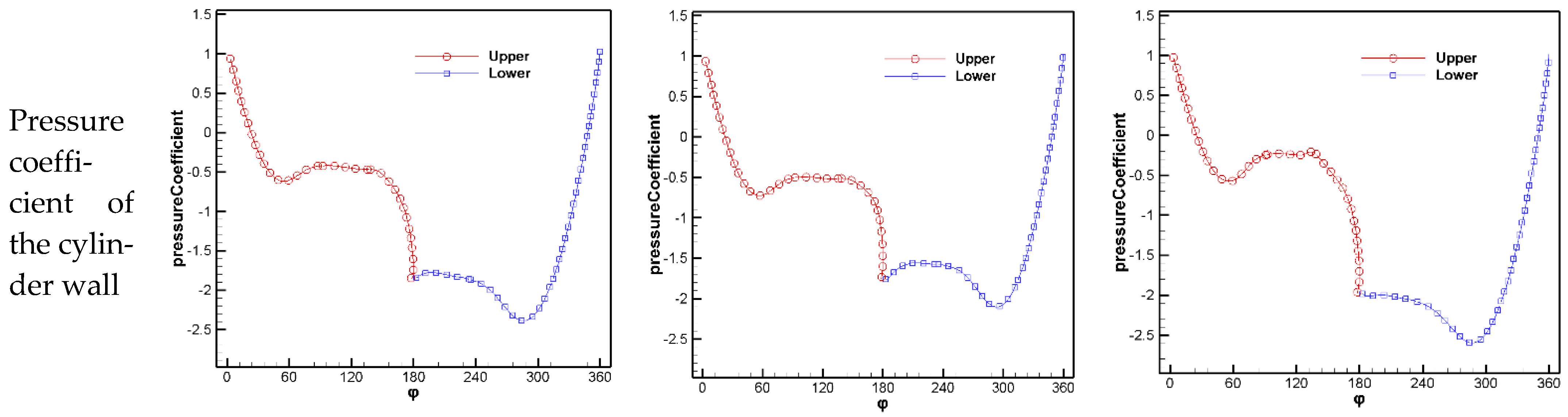
3.1. Effect of T/T0
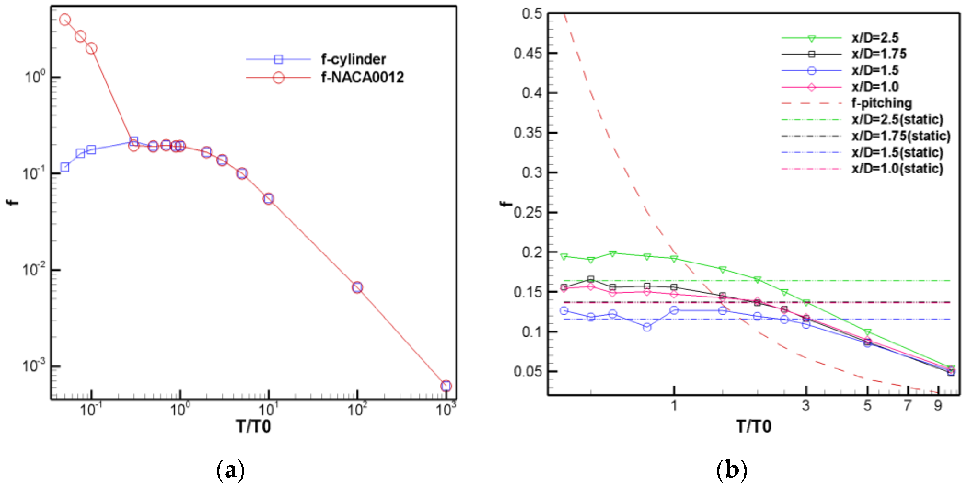
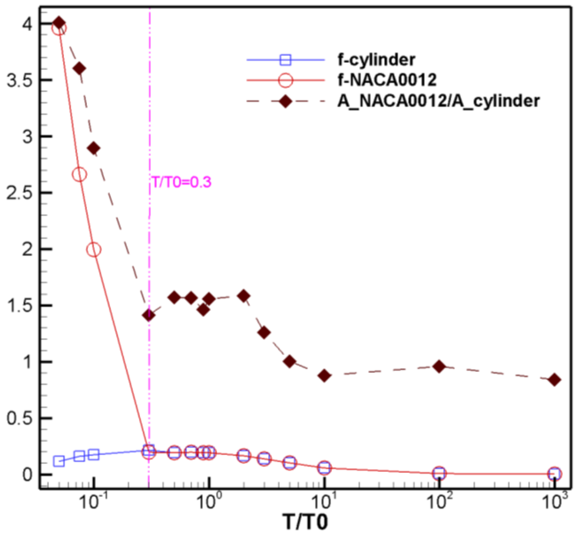
3.1.1. Influence on Vortex Shedding Frequency
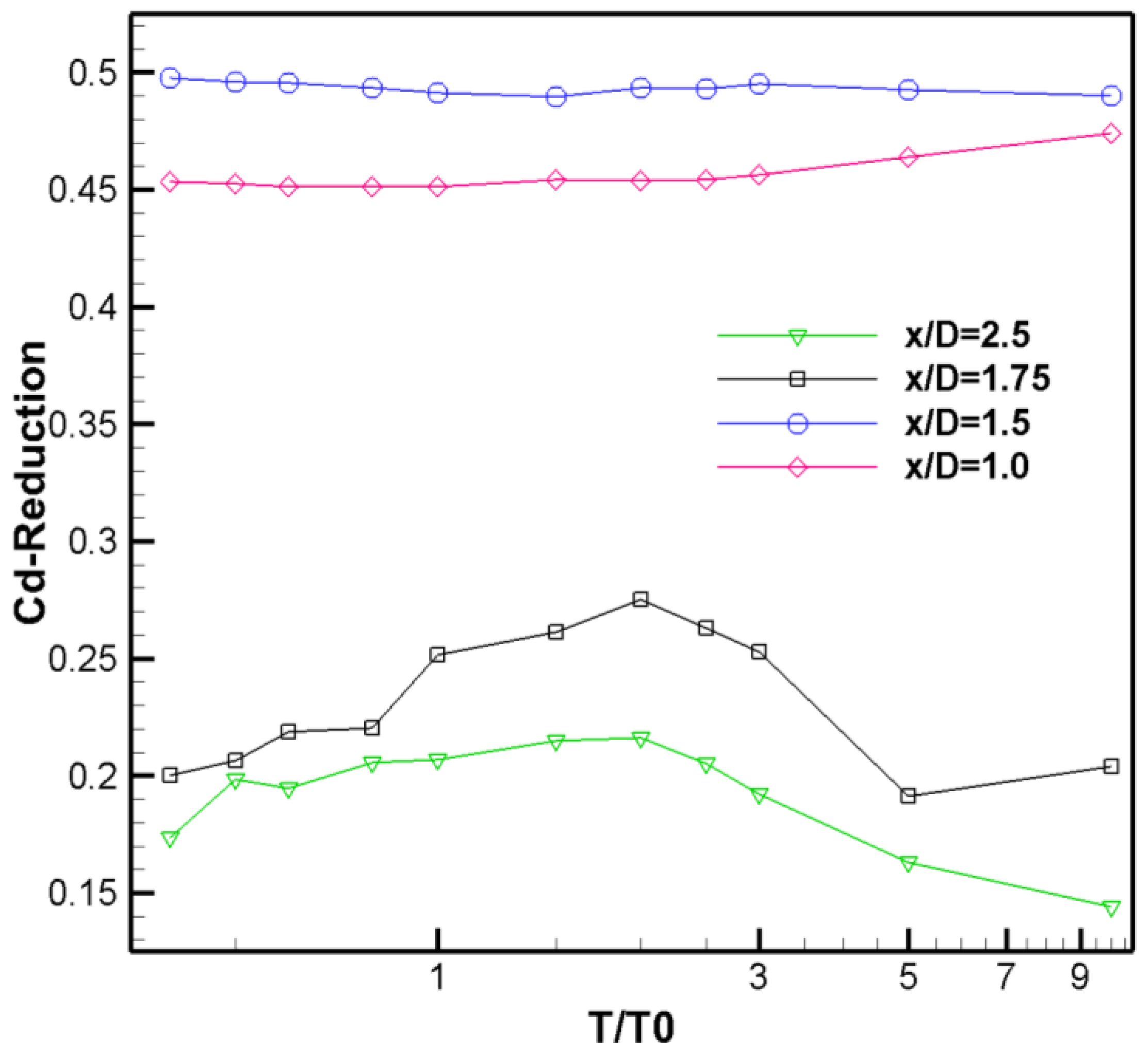
3.1.2. Influence on Drag Reduction Characteristics
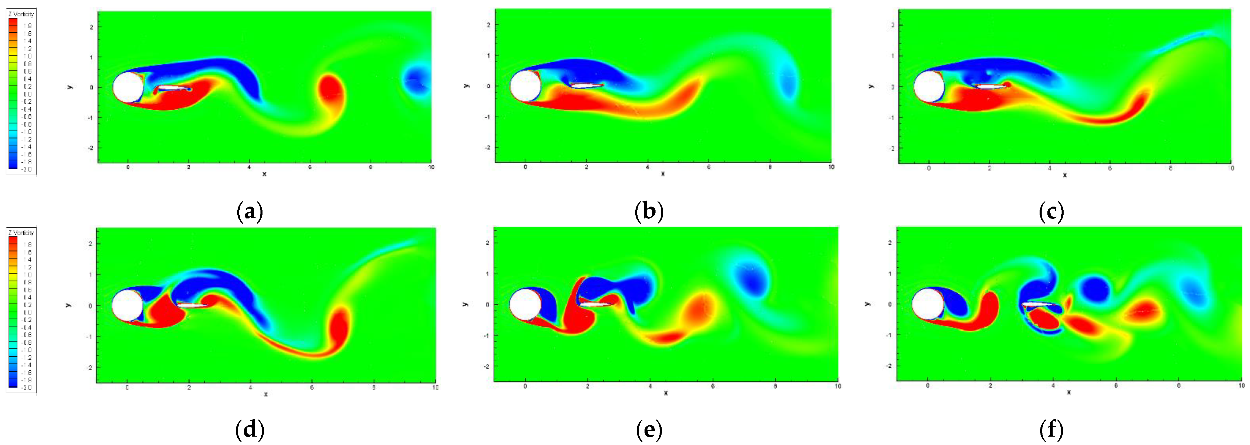
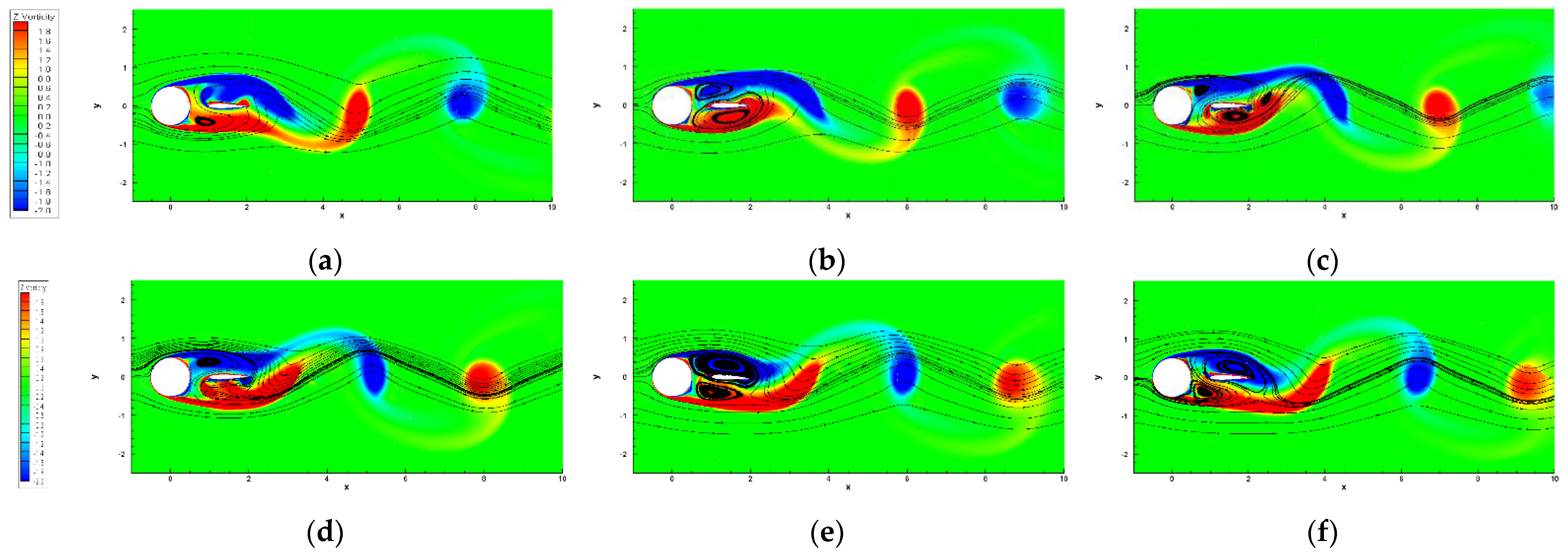
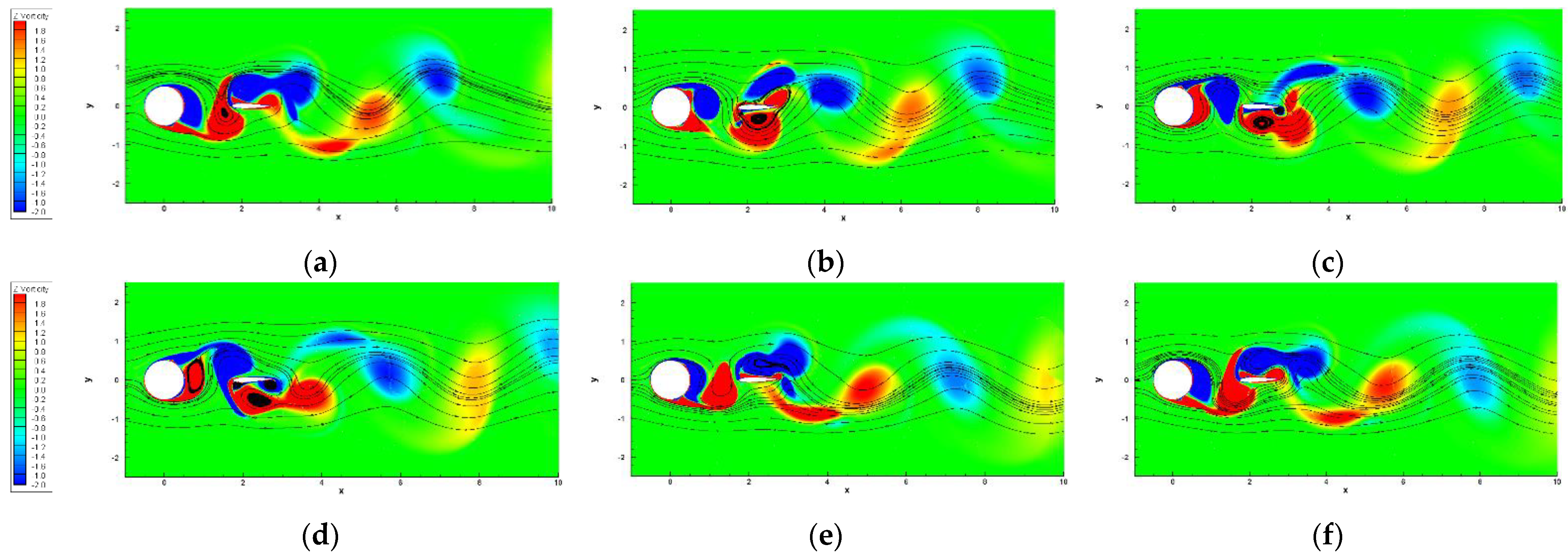
3.2. Effect of x/D
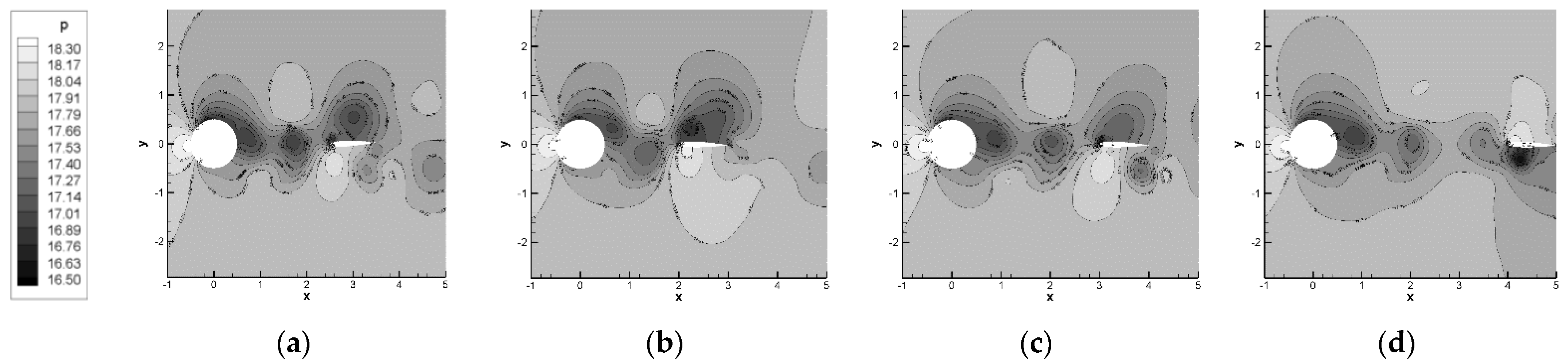
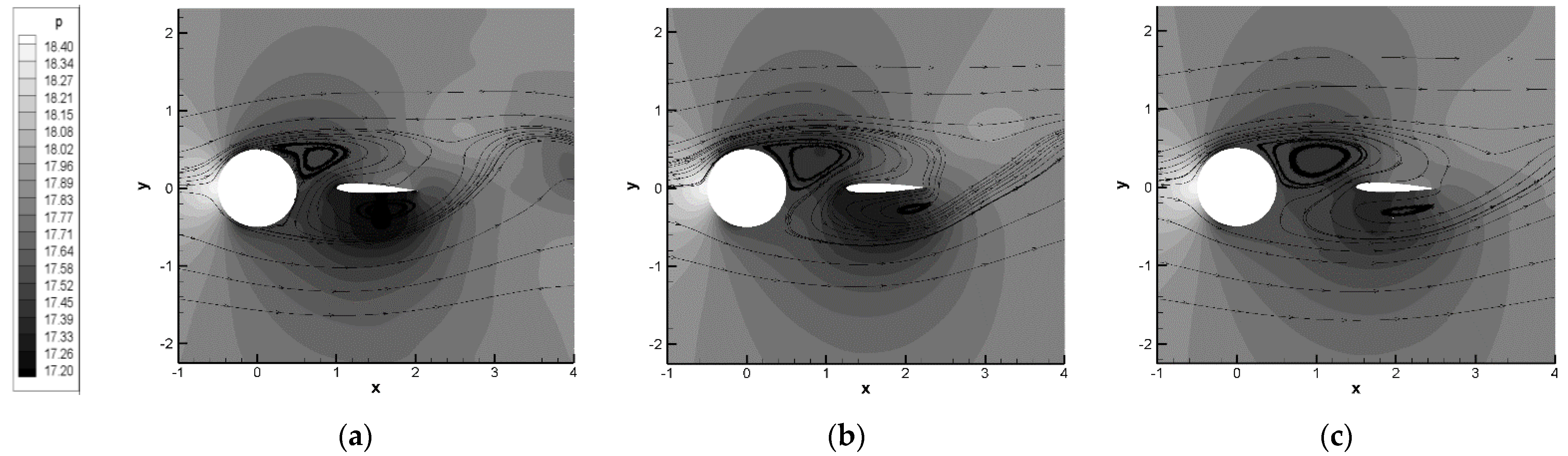
3.2.1. Influence on the Flow Mechanism
3.2.2. Influence on the Vortex Shedding Frequency
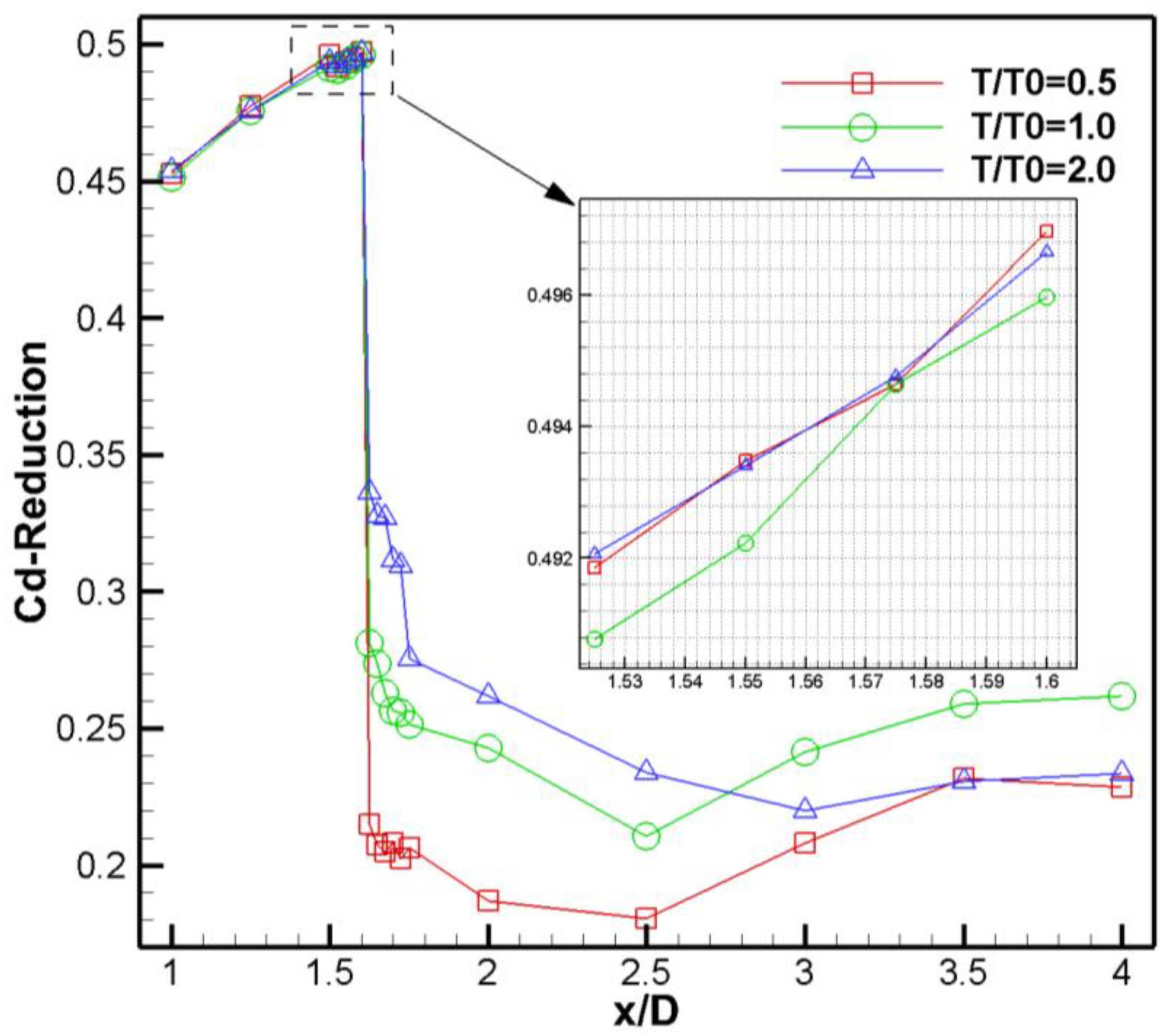
3.2.3. Influence on Drag Reduction Characteristics
4. Conclusions
- When T/T0 is greater than a critical value, the aerodynamic coefficients of the cylinder and the airfoil will vary in accordance with the same frequency, i.e., the phenomenon of “aerodynamic coupling” will occur. According to our simulation results, the ratio of the amplitudes corresponding to the aerodynamic coefficients’ fundamental frequency of the cylinder and the airfoil is essential for aerodynamic coupling.
- When x/D ≤ 1.5, the drag reduction rate will vary slightly with the increase of T/T0, reaching above 45%. Conversely, when x/D ≥ 1.75, a small drag reduction rate will be found (less than 30%). As T/T0 increases, the drag reduction rate will first increase and then decrease with the maximum value taken around T/T0 = 2.0.
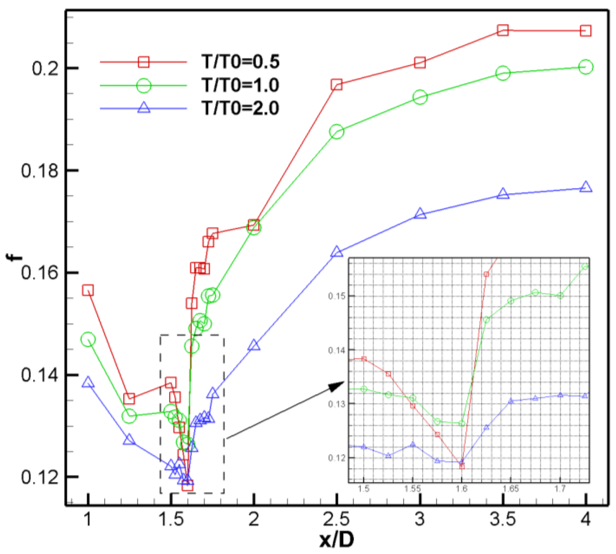
- Evolutionary modes of the flow field before and after x/D = 1.6 are various, too. When x/D ≤ 1.6, the coupling frequency will decrease with the increase of x/D, and the smallest coupling frequency will be observed near x/D = 1.6. The coupling frequency will be on the rise after x/D ≥ 1.625, becoming stabilized after x/D > 3.5, since the airfoil has a decreased suppression effect on vortex shedding.
- When x/D ≤ 1.6, influenced by the airfoil, complete vortex shedding cannot form at the trailing edge of the cylinder. Moreover, the primary vortex may result in a significant decline on the drag coefficient of the tandem configuration. The drag reduction rate at x/D = 1.6 can reach above 50% (under the premise of pneumatic coupling). When x/D ≥ 1.625, the alternately shedding vortex street will be observed between the cylinder and the airfoil, from which the drag coefficient of tandem configuration will sharply increase and then become stabilized with the rising x/D.
Author Contributions
Funding
Institutional Review Board Statement
Informed Consent Statement
Data Availability Statement
Conflicts of Interest
References
- Ericsson, L.E.; Pavish, D. Aeroelastic vehicle dynamics of a proposed delta II 7920-10L launch vehicle. J. Spacecr. Rocket. 2000, 37, 28–38. [Google Scholar] [CrossRef]
- Bartels, R.E.; Chwalowski, P.; Massey, S.J.; Heeg, J.; Mineck, R.E. Computational aeroelastic analysis of the Ares I crew launch vehicle during ascent. J. Spacecr. Rocket. 2012, 49, 651–658. [Google Scholar] [CrossRef]
- Yuan, W.; Wall, A.; Lee, R. Combined numerical and experimental simulations of unsteady ship airwakes. Comput. Fluids 2018, 172, 29–53. [Google Scholar] [CrossRef]
- Dooley, G.; Martin, J.E.; Buchholz, J.H.; Carrica, P.M. Ship airwakes in waves and motions and effects on helicopter operation. Comput. Fluids 2020, 208, 104627. [Google Scholar] [CrossRef]
- Zakeri, A.; Høeg, K.; Nadim, F. Submarine debris flow impact on pipelines—Part I: Experimental investigation. Coast. Eng. 2008, 55, 1209–1218. [Google Scholar] [CrossRef]
- Akbari, H.; Pooyarad, A. Wave force on protected submarine pipelines over porous and impermeable beds using SPH numerical model. Appl. Ocean. Res. 2020, 98, 102118. [Google Scholar] [CrossRef]
- Xiong, Q.; Lim, A.E.; Lim, Y.; Lam, Y.C.; Duan, H. Dynamic magnetic nanomixers for improved microarray assays by eliminating diffusion limitation. Adv. Healthc. Mater. 2019, 8, 1801022. [Google Scholar] [CrossRef] [PubMed]
- Lim, A.E.; Lim, C.Y.; Lam, Y.C.; Lim, Y.H. Effect of microchannel junction angle on two-phase liquid-gas Taylor flow. Chem. Eng. Sci. 2019, 202, 417–428. [Google Scholar] [CrossRef]
- Choi, H.; Jeon, W.P.; Kim, J. Control of Flow over a Bluff Body. Annu. Rev. Fluid Mech. 2008, 40, 113–139. [Google Scholar] [CrossRef] [Green Version]
- Yin, J.F.; You, Y.X.; Li, W.; Hu, T.Q. Numerical analysis for the characteristics of flow control around a circular cylinder with a turbulent boundary layer separation using the electromagnetic force. Acta Phys. Sin. 2014, 63, 044701. (In Chinese) [Google Scholar]
- Jeon, S.; Choi, J.; Jeon, W.P.; Choi, H.; Park, J. Active control of flow over a sphere for drag reduction at a subcritical Reynolds number. J. Fluid Mech. 2004, 517, 113–129. [Google Scholar] [CrossRef] [Green Version]
- Kimura, T.; Tsutahara, M. Fluid dynamic effects of grooves on circular cylinder surface. AIAA J. 1991, 29, 2062–2068. [Google Scholar] [CrossRef]
- Kwon, K.; Choi, H. Control of laminar vortex shedding behind a circular cylinder using splitter plates. Phys. Fluids 1996, 8, 479–486. [Google Scholar] [CrossRef]
- Sun, X.; Suh, S.; Ye, Z.H.; Yu, B. Dynamics of a circular cylinder with an attached splitter plate in laminar flow: A transition from vortex-induced vibration to galloping. Phys. Fluids 2020, 32, 027104. [Google Scholar] [CrossRef]
- Ghiasi, A.; Razavi, S.E.; Rouboa, A.; Mahian, O. Numerical study on flow over a confined oscillating cylinder with a splitter plate. Int. J. Numer. Methods Heat Fluid Flow 2019, 29, 1629–1646. [Google Scholar] [CrossRef]
- An, X.Y.; Song, B.W.; Tian, W.L.; Ma, C.C. Numerical Research of Flow past a Circular Cylinder with Splitter Plate at a Subcritical Reynolds Number Region. J. Shanghai Jiaotong Univ. Sci. 2019, 24, 113–121. [Google Scholar] [CrossRef]
- Anderson, E.A.; Szewczyk, A.A. Effects of a splitter plate on the near wake of a circular cylinder in 2 and 3-dimensional flow configurations. Exp. Fluids 1997, 23, 161–174. [Google Scholar] [CrossRef]
- Apelt, C.J.; West, G.S.; Szewczyk, A.A. The effects of wake splitter plates on the flow past a circular cylinder in the range 104<R<5 × 10⁴. J. Fluid Mech. 1973, 61, 187–198. [Google Scholar] [CrossRef]
- Apelt, C.J.; West, G.S. The effects of wake splitter plates on the flow past a circular cylinder in the range 104<R<5 × 10⁴. Part 2. J. Fluid Mech. 1975, 71, 145–160. [Google Scholar] [CrossRef]
- Roshko, A. On the Wake and Drag of Bluff Bodies. J. Aeronaut. Sci. 1955, 22, 124–132. [Google Scholar] [CrossRef]
- Hwang, J.Y.; Yang, K.S.; Sun, S.H. Reduction of flow-induced forces on a circular cylinder using a detached splitter plate. Phys. Fluids 2003, 15, 2433–2436. [Google Scholar] [CrossRef]
- Ozono, S. Flow control of vortex shedding by a short splitter plate asymmetrically arranged downstream of a cylinder. Phys. Fluids 1999, 11, 2928–2934. [Google Scholar] [CrossRef]
- Bearman, P.W.; Zdravkovich, M.M. Flow around a circular cylinder near a plane boundary. J. Fluid Mech. 1978, 89, 33–47. [Google Scholar] [CrossRef]
- Rathakrishnan, E. Effect of Splitter Plate on Bluff Body Drag. AIAA J. 1999, 37, 1125–1126. [Google Scholar] [CrossRef]
- Bingham, C.; Morton, C.; Martinuzzi, E.J. Influence of control cylinder placement on vortex shedding from a circular cylinder. Exp. Fluids 2018, 59, 158. [Google Scholar] [CrossRef]
- Chauhan, B.V.S.; Singh, V.P.; Sayyed, I.; Vedratnam, A. Flow pattern determination for circular staggered cylinders in cross flow using CFD. Civ. Eng. 2020, 5, 82–95. [Google Scholar]
- Strykowski, P.J.; Sreenivasan, K.R. On the formation and suppression of vortex ’shedding’ at low Reynolds numbers. J. Fluid Mech. 1990, 218, 71–107. [Google Scholar] [CrossRef]
- Wang, G.X.; Wang, S.Y.; Ge, M.M.; Deng, X.G. High-order delay detached-eddy simulations of cylindrical separated vortex/vortex induced noise based on transition model and acoustic analogy. Acta Phys. Sin. 2018, 67, 194701. [Google Scholar]
- Zhang, Z.; Wang, Z.; Gursul, I. Lift Enhancement of a Stationary Wing in a Wake. AIAA J. 2020, 58, 4613–4619. [Google Scholar] [CrossRef]
- Gopalkrishnan, R.; Triantafyllou, M.S.; Triantafyllou, G.S.; Barrett, D.S. Active Vorticity Control in a Shear Flow Using a Flapping Foil. J. Fluid Mech. 1994, 274, 1–21. [Google Scholar] [CrossRef] [Green Version]
- Streitlien, K.; Triantafyllou, G.S.; Triantafyllou, M.S. Efficient foil propulsion through vortex control. AIAA J. 1996, 34, 2315–2319. [Google Scholar] [CrossRef]
- Chao, L.M.; Zhang, D.; Cao, Y.H.; Pan, G. Numerical studies on the interaction between two parallel D-cylinder and oscillated foil. Mod. Phys. Lett. B 2018, 32, 1850034. [Google Scholar] [CrossRef]
- Xiao, Q.; Sun, K.; Liu, H.; Hu, J.X. Computational study on near wake interaction between undulation body and a D-section cylinder. Ocean. Eng. 2011, 38, 673–683. [Google Scholar] [CrossRef]
- Spalart, P.R.; Allmaras, S.R. One-equation turbulence model for aerodynamic flows. Rech. Aerosp. 1994, 1, 5–21. [Google Scholar]
- Roe, P.; Pike, J. Efficient construction and utilisation of approximate Riemann solutions. Comput. Methods Appl. Sci. Eng. 1984, 43, 499–518. [Google Scholar]
- Yoon, S.; Jameson, A. Lower-upper symmetric-gauss-seidel method for the euler and navier-stokes equations. AIAA J. 1988, 26, 1025–1026. [Google Scholar] [CrossRef] [Green Version]
- Zhang, L.P.; Wang, Z.J. A block LU-SGS implicit dual time-stepping algorithm for hybrid dynamic meshes. Comput. Fluids 2004, 33, 891–916. [Google Scholar] [CrossRef]
- Chang, X.H.; Zhang, L.P.; He, X. Numerical study of the thunniform mode of fish swimming with different Reynolds number and caudal fin shape. Comput. Fluids 2021, 68, 54–70. [Google Scholar] [CrossRef]
- Chang, X.H.; Ma, R.; Zhang, L.P. Parallel implicit hole-cutting method for unstructured overset grid. Acta Aeronaut. Astronaut. Sin. 2018, 39, 121780. (In Chinese) [Google Scholar]
- Landon, R.H. NACA0012 oscillation and transient pitching. In Compendium of Unsteady Aerodynamic Measurements: Advisory Report 702; AGARD: Hampton, VA, USA, 1982. [Google Scholar]
- Duan, X.P. Dynamic Hybrid Grid Generation Method for Complex Geomtries and Numerical Method for Unsteady Compressible Flows; Aerodynamics Research and Development Center: Mianyang, China, 2008; pp. 69–72. (In Chinese) [Google Scholar]


| Variable Name | Value |
|---|---|
| Mach number (Ma) | 0.2 |
| Reynolds number (Re) | 5000 |
| Inflow velocity (U∞)/m.s−1 | 34.0 |
| Inflow temperature (T∞)/K | 300 |
| Wall temperature (Tw)/K | 294 |
| Average attack angle (∆α)/° | 0 |
| Oscillation amplitude (αm)/° | 2.44 |
| Characteristic | ∆x/mm | Mesh Quantity | Vortex Shedding Period (T)/s |
|---|---|---|---|
| Coarse | 0.01 | 38391 | 0.204 |
| Moderate | 0.001 | 42417 | 0.208 |
| Refined | 0.0005 | 44232 | 0.208 |
Publisher’s Note: MDPI stays neutral with regard to jurisdictional claims in published maps and institutional affiliations. |
© 2021 by the authors. Licensee MDPI, Basel, Switzerland. This article is an open access article distributed under the terms and conditions of the Creative Commons Attribution (CC BY) license (https://creativecommons.org/licenses/by/4.0/).
Share and Cite
Han, R.; Liu, W.; Yang, X.-L.; Chang, X.-H. Effect of NACA0012 Airfoil Pitching Oscillation on Flow Past a Cylinder. Energies 2021, 14, 5582. https://doi.org/10.3390/en14175582
Han R, Liu W, Yang X-L, Chang X-H. Effect of NACA0012 Airfoil Pitching Oscillation on Flow Past a Cylinder. Energies. 2021; 14(17):5582. https://doi.org/10.3390/en14175582
Chicago/Turabian StyleHan, Rong, Wei Liu, Xiao-Liang Yang, and Xing-Hua Chang. 2021. "Effect of NACA0012 Airfoil Pitching Oscillation on Flow Past a Cylinder" Energies 14, no. 17: 5582. https://doi.org/10.3390/en14175582
APA StyleHan, R., Liu, W., Yang, X.-L., & Chang, X.-H. (2021). Effect of NACA0012 Airfoil Pitching Oscillation on Flow Past a Cylinder. Energies, 14(17), 5582. https://doi.org/10.3390/en14175582