Article

Design and Analysis of a Novel Axial-Radial Flux Permanent Magnet Machine with Halbach-Array Permanent Magnets

1
School of Energy and Environment, City University of Hong Kong, Hong Kong, China
2
Shenzhen Research Institute, City University of Hong Kong, Shenzhen 518057, China
*
Author to whom correspondence should be addressed.
Energies 2021, 14(12), 3639; https://doi.org/10.3390/en14123639
Submission received: 17 May 2021 / Revised: 14 June 2021 / Accepted: 15 June 2021 / Published: 18 June 2021

Abstract

:
Electric machines with high torque density are needed in many applications, such as electric vehicles, electric robotics, electric ships, electric aircraft, etc. and they can avoid planetary gears thus reducing manufacturing costs. This paper presents a novel axial-radial flux permanent magnet (ARFPM) machine with high torque density. The proposed ARFPM machine integrates both axial-flux and radial-flux machine topologies in a compact space, which effectively improves the copper utilization of the machine. First, the radial rotor can balance the large axial forces on axial rotors and prevent them from deforming due to the forces. On the other hand, the machine adopts Halbach-array permanent magnets (PMs) on the rotors to suppress air-gap flux density harmonics. Also, the Halbach-array PMs can reduce the total attracted force on axial rotors. The operational principle of the ARFPM machine was investigated and analyzed. Then, 3D finite-element analysis (FEA) was conducted to show the merits of the ARFPM machine. Demonstration results with different parameters are compared to obtain an optimal structure. These indicated that the proposed ARFPM machine with Halbach-array PMs can achieve a more sinusoidal back electromotive force (EMF). In addition, a comparative analysis was conducted for the proposed ARFPM machine. The machine was compared with a conventional axial-flux permanent magnet (AFPM) machine and a radial-flux permanent magnet (RFPM) machine based on the same dimensions. This showed that the proposed ARFPM machine had the highest torque density and relatively small torque ripple.

1. Introduction

As an important component of an electric powertrain system, electric machines are welcomed widely in electric vehicles, electrified aircraft, robots, and so on [1,2,3]. The radial flux permanent magnet (RFPM) machine is a major subject in research and has wide applications. The development of the RFPM machines is very mature. However, in many applications, mechanical gears are necessary to improve the torque, while they increase the manufacture and maintenance cost, as well as the system volume [4,5,6]. In order to avoid the mechanical gears, the axial flux permanent magnet (AFPM) machine has recently attracted much attention from scholars [7,8,9]. The high aspect ratio gives them many advantages such as compactness, high torque density, and good heat dissipation [10,11], which makes AFPM machines very suitable for direct-drive systems [12].
There are many topologies of AFPM machines designed for direct-drive systems. The large aspect ratio contributes to space saving in many applications. Vernier permanent magnet (PM) topologies can also be adopted in AFPM machines [13]. They can improve torque density in AFPM machines as in RFPM machines. Halbach-array PMs can be applied in AFPMs to improve the amplitude and reduce the harmonic distortion of the air-gap flux density waveform [14]. In order to make full use of material, double-sided structures are usually adopted, which also reduces the occupied room, so some AFPM machines comprise a stator and two rotors [15,16]. The stator with toroidal windings or drum windings is sandwiched between two rotors [17,18]. The two kinds of structure have different merits. For example, YASA machines with drum windings can eliminate stator back iron, which can reduce material and volume [19,20]. As for the topologies with toroidal windings, they have the same length of winding ends for concentrated windings and distributed windings. Besides the double-side AFPM machines, the multi-disc AFPM machine is also proposed to increase the electromagnetic torque for a propulsion system [21].
However, these structures cannot avoid problems such as ending effect and copper loss brought about by winding ends. Another drawback of the AFPM machine is that the axial force on the rotor is very large, which may cause rotor tilting and deforming. Robustness is a very important standard to evaluate whether an electric machine can be applied in industry. The rotor tilt is the major reason for the eccentricity fault in an AFPM machine, which can result in unbalanced back electromotive force (EMF) [22,23]. The large axial force is also a large burden for bearings. Under large loads, bearings are more susceptible to damage, which will lead to the breakdown of electric machines and increase the cost of maintenance. In addition, there will be large harmonics in the air-gap magnetic flux density when the rotor PMs are too close to the stator. The typical case is that slots on the stator are rectangular, while PMs on the rotor are fan-shaped. It will deteriorate the air-gap flux density. Reference [24] proposes an AFPM machine with sinusoidal rotor segments. The sinusoidal rotor segments can provide variable gaps to reduce the harmonics in the air-gap flux density, but this has high requirements for materials. It has to be made of a special material with easy machinability and high magnetic permeability. Due to the protruding part of rotor segments, the equivalent air-gap length is relatively large, which will reduce the air-gap flux density.
This paper proposes a novel axial-radial flux permanent magnet (ARFPM) machine with Halbach-array PMs to solve the above problems. The proposed ARFPM machine integrates the axial flux and radial flux with two axial rotors and one radial rotor. This article is organized as follows. Section 2 discusses the structure and operational principle of the ARFPM machine. The parametric study and optimization of the ARFPM machine are performed in Section 3. In Section 4, 3D finite element analysis (FEA) is conducted to compare the performances of the proposed ARFPM machine with those of the AFPM machine and RFPM machine. Finally, the conclusion is drawn in Section 5.

2. Structure and Operational Principle

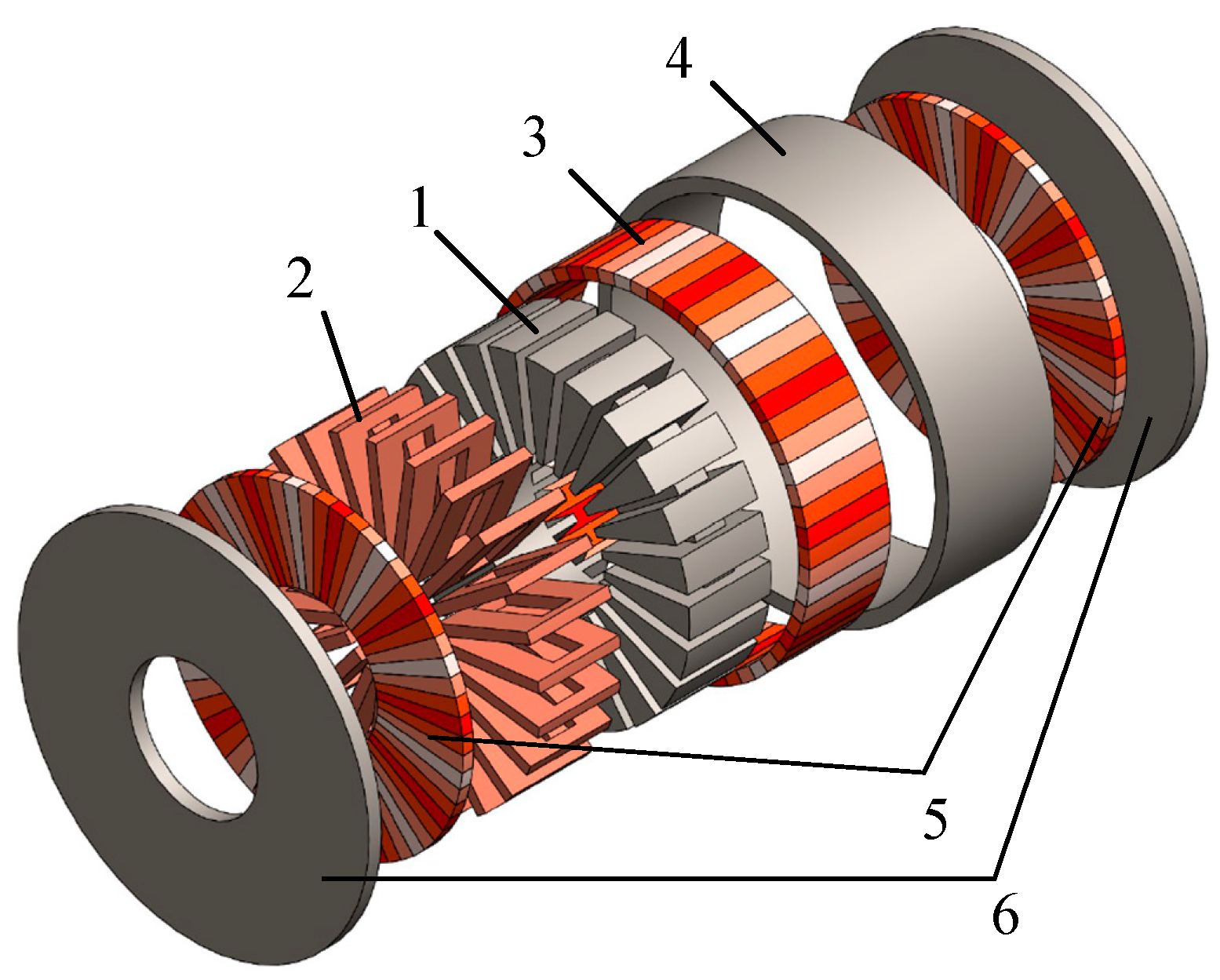
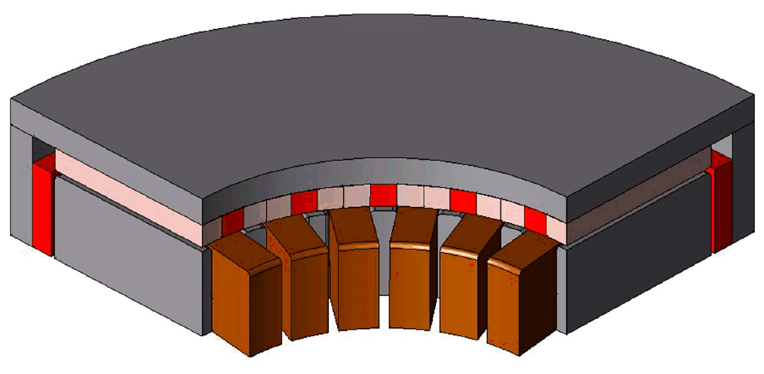
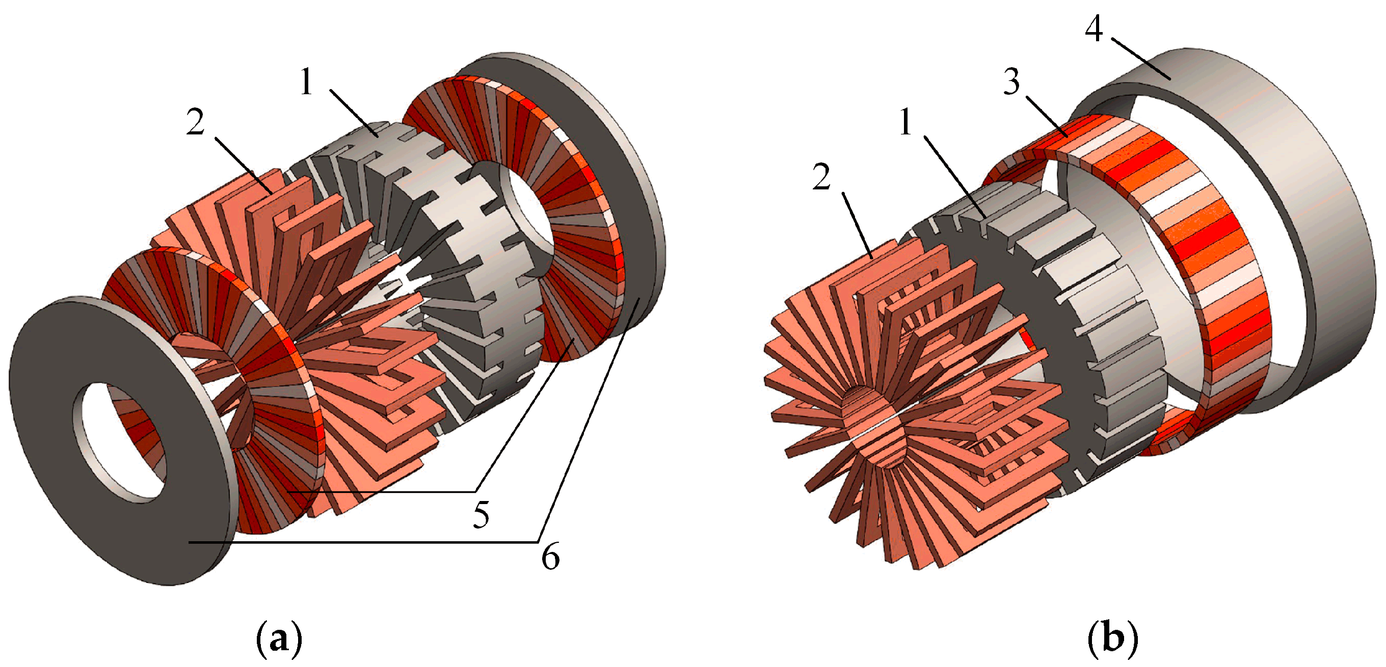
2.1. Structure of Axial-Radial Flux Permanent Magnet (ARFPM) Machine

As shown in Figure 1, the proposed ARFPM machine is composed of one stator, two axial rotors, and one radial rotor. Because the end of drum windings is useless, the machine adopts toroidal windings, which are wound around the stator core. Figure 2 shows the shape of toroidal windings applied in the ARFPM machine. The exterior components of the windings are utilized to reduce half of the ends. Thus, the stator is equipped with opening slots on three faces. PMs are mounted on the surface of rotors. Due to the toroidal windings, North–North (NN) type axial rotors are adopted. The radial rotor is fixed and aligned with two axial rotors, which can avoid the tilt of axial rotors and keep the same phase of air-gap flux density. A classical pole-slot combination, 20-pole-24slot configuration, is adopted in the ARFPM machine. Compared with integer-slot concentrated winding machines, fractional-slot concentrated winding machines can enhance flux-weakening capability and reduce cogging torque [25,26].
In order to suppress the harmonics of air-gap magnetic flux, the PMs are arranged as a Halbach array [27,28]. It can also intensify the magnetic flux density in the air gap. The magnetization direction of PMs is related to the number of segments per pole pair. As shown in Figure 3a, in case the PMs are too narrow to be manufactured, each pole pair is divided into six segments, so the magnetization direction of each segment varies by 60° in turn. Figure 3b shows the schematic diagram of the normal and tangential residual magnetization distribution of each segment. By contrast with the conventional arranged PMs, the normal residual magnetization distribution of Halbach-array PMs is not a square waveform, and the tangential residual magnetization distribution is also smaller.

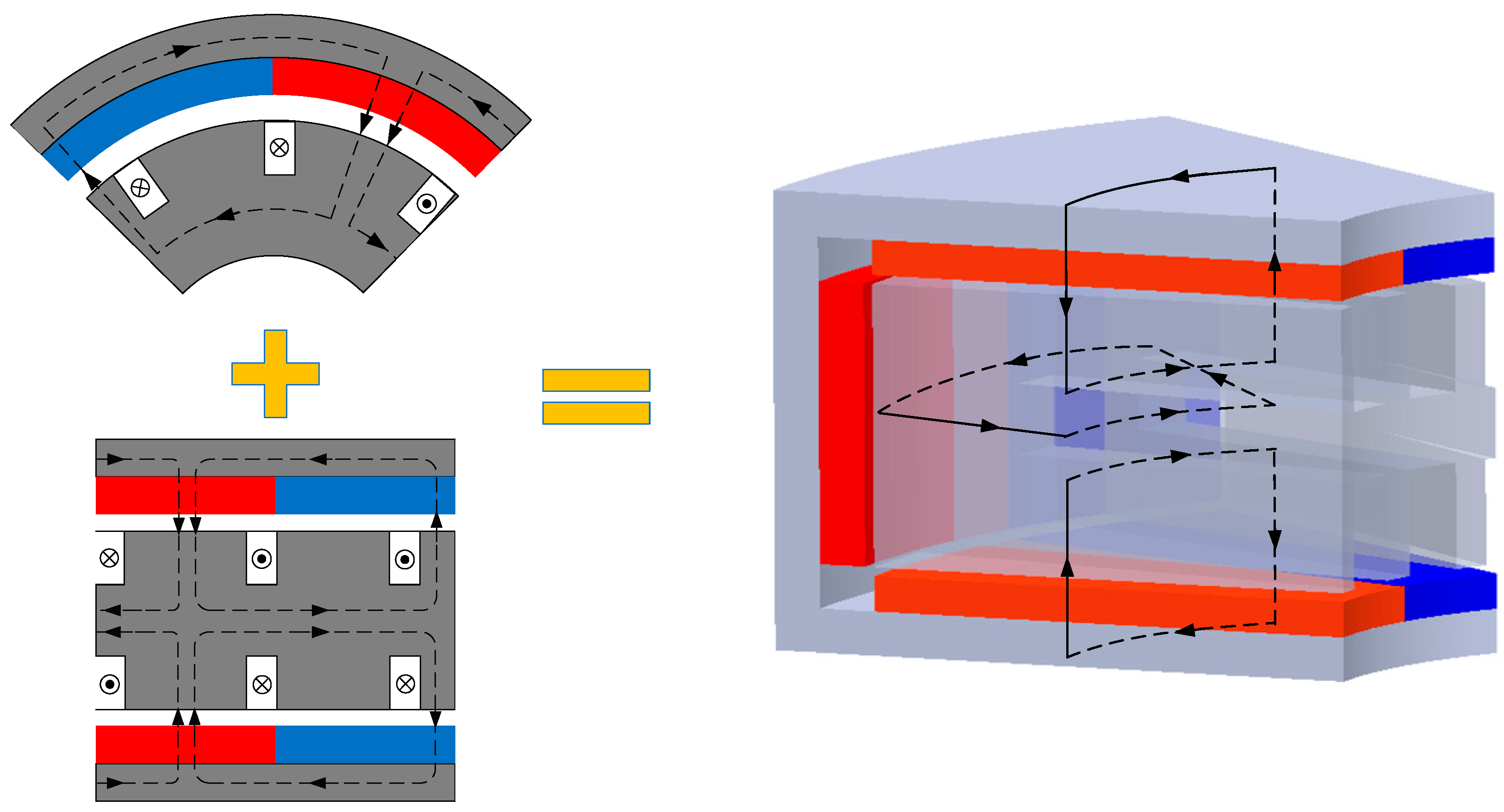
2.2. Operational Principle of ARFPM Machine

According to Figure 1, the ARFPM machine combines a double-sided AFPM machine and a RFPM machine. The active windings contain three parts that correspond to three rotors. Figure 4 is a schematic diagram of the magnetic flux paths in the ARFPM machine. In order to simplify the diagram, conventional arranged PMs are drawn in Figure 4. There is no apparent difference in the magnetic flux paths between Halbach-array PMs and conventional arranged PMs. The magnetic flux paths in the machine are mainly divided into two parts. The first part is caused by the radial rotor. The magnetic flux generated by the radial PMs goes from the radial rotor to the stator in the radial direction. It flows in a 2D plane. The second part is related to the axial rotors. The magnetic flux generated by the axial PMs goes through the air gap from one axial rotor to the stator in axial direction. Then it travels in the stator in the circumferential direction and goes back from the same side of the stator to the corresponding rotor. Hence, there are radial, axial, and circumferential components of magnetic flux in the stator core. This means that the total magnetic flux flows in a 3D plane.
Due to its combination of an AFPM machine and a RFPM machine, the ARFPM machine has a very similar operational principle to them. Because the expressions of back EMF for AFPM machines and RFPM machines are the same [29], the back EMF and electromagnetic torque of the ARFPM machine can be expressed as (1) and (2), respectively.
E = p N 60 a Φ a v n
T e m = p N 2 π a Φ a v I
where p is the number of pole pairs, a is the number of parallel branch pairs, Φav is the average magnetic flux per pole, N is the number of coils, n is the rotor speed, I is the current in coils. Φav is determined by the average air-gap flux density Bav and the air-gap areas per pole, so it can be defined as:
Φ a v = B a v 2 p ( π 4 ( D o 2 D i 2 ) + π D o l )
where Do and Di are the outer and inner diameter, respectively, l is the axial length of the stator. The average magnetic flux per pole shows that the areas in the ARFPM machine are enlarged by the radial rotor. Hence, the back EMF and electromagnet torque will also be improved.
The ampere turns NI can also be defined as:
N I = A J
where A is the cross-sectional area of slots, J is the current density. The cross-sectional area of each rectangular slot is the product of the width and depth of the slot. Hence, if the width of the slots is enlarged, the ampere turns NI will also be increased. Then, the cross-sectional area A is determined by the inner diameter Di when the depth of slots is constant. However, the width of the slots cannot be too long because the sum of the width of all the slots cannot exceed the inner circumference of the stator.
When (3) and (4) are substituted for (2), the electromagnetic torque of the ARFPM machine can be derived as:
T e m = p A J 2 π a B a v 2 p ( π 4 ( D o 2 D i 2 ) + π D o l )
when the inner diameter Di is reduced, the item in the bracket of (5) will be increased, but the cross-sectional area of slots A will be reduced. In addition, the average air-gap flux density Bav is greatly affected by the air-gap depth, which can influence the back EMF and electromagnetic torque directly. The large air-gap depth will lead to small air-gap flux density, but a small air-gap depth will cause many harmonics in the flux density. It is hard to determine the trend of the electromagnetic torque Tem, so a detailed discussion is needed.

3. Parametric Study of ARFPM Machine

The magnetic flux in the stator contains the axial, radial, and circumferential components. It cannot be transformed into a 2D linear machine to be optimized as in. Thus, a 3D finite element analysis (FEA) is conducted to obtain an optimal geometry of the ARFPM machine. Due to the very large computational burden, this paper adopts a parametric study to optimize the geometry. A 3D model of the ARFPM machine is built with the finite element software JMAG-Designer. In order to reduce the number of meshes and computational time, a partial model is constructed. Figure 5 shows a 1/8 model of the ARFPM machine. The partial model contains 2,897,124 numbers of 3D mesh. According to the operational principle of the proposed machine, the effects of PM arrangement and air-gap depth for back EMF and electromagnetic torque are consistent because they both affect the average air-gap flux density directly when other dimensions are kept constant. Thus, the PM arrangement and air-gap depth can be optimized firstly in order to reduce the harmonics. Then the inner diameter can be optimized to obtain the largest electromagnetic torque.

3.1. Study on Air-Gap Flux Density and Back Electromotive Force (EMF)

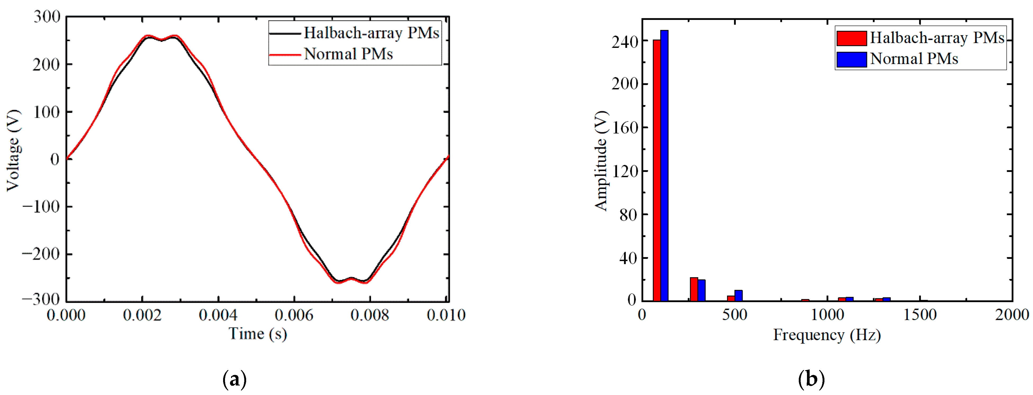
3.1.1. Impact of Permanent Magnet (PM) Arrangement

The arrangement of PMs has a direct influence on the air-gap flux density. Conventional arranged PMs are all magnetized in the axial direction, which will produce a square waveform of air-gap magnetic flux density. This means that many high-order harmonics are contained in the air-gap flux density. This will distort the back EMF when the air-gap depth is too small. However, Halbach-array PMs can alleviate the problem. Different magnetizations can reduce some harmonics. The normal air-gap magnetic flux densities produced by conventional PMs and Halbach-array PMs are shown in Figure 6.
The PMs are mounted on the axial rotor produce axial magnetic flux density, while the radial rotor PMs produce the radial one. As seen from Figure 6, the amplitudes of normal air-gap flux density generated by the axial and radial rotors are the same, although the directions are different. The air-gap flux density produced by the Halbach-array PMs is more similar to a sinusoidal waveform, which may lead to fewer harmonics in the back EMF. Figure 7a,b show the tangential air-gap magnetic flux density generated by conventional PMs and Halbach-array PMs, respectively. As seen from Figure 7a, the tangential flux density near the center of a PM is 0 because the PM is axial magnetization. The waveform of air-gap flux density in Figure 7b shows the Halbach arrangement. The peak value is smaller than that in Figure 7a. The tangential flux density cannot be utilized. Thus, this means that there is less flux leakage in the air gap. The troughs are caused by the axial magnetized PMs and slots on the stator.
The no-load back EMF of machines with conventional PMs and Halbach-array PMs is shown in Figure 8a. The amplitude of back EMF in the machine with conventional PMs is larger, which is also proved by the fast Fourier transform (FFT) in Figure 8b. Figure 8b shows that the amplitudes of the fifth harmonic are smaller in the ARFPM machine with Halbach-array PMs, while that of the third harmonic is larger.
Due to the star connection of windings, the third harmonic will be eliminated. Except for the fifth harmonic, the amplitudes of higher harmonics are too small to be considered. Hence, primary attention should be paid to the fifth harmonic. The amplitude ratio of the fifth harmonic to the fundamental component in the machine with conventional PMs is 3.98%, while that in the machine with Halbach-array PMs is 2.03%. The conventional PMs can lead to two times the percent of fifth harmonic compared to that in Halbach-array PMs. Furthermore, it is hard to eliminate the fifth harmonic in the machine control, which can cause large torque ripples. Then, the Halbach-array PMs are necessary for the proposed machine.

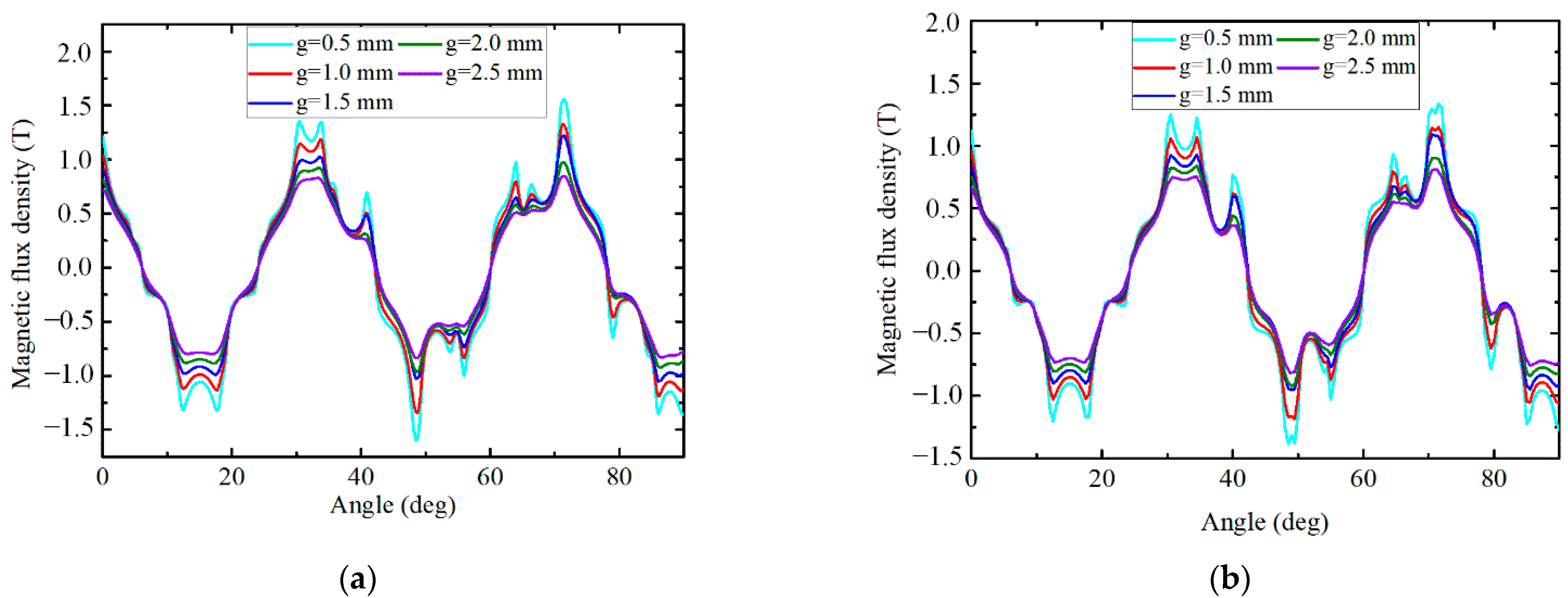
3.1.2. Impact of Air-Gap Depth

The depth of the air gap is also the main factor affecting the performance of machines. When the air gap is small, the ARFPM machine will have less flux leakage between the stator and rotor, so the air-gap magnetic flux density can be increased. Figure 9a,b show the axial and radial air-gap magnetic flux density, respectively. The magnetic flux densities at different depths of air gaps are compared. As seen from Figure 9, the shapes of axial and radial flux densities at different air-gap depths are the same. It means the shape of normal air-gap magnetic flux density has nothing to do with the depth of the air gap.
It is shown in Figure 9 that the amplitude of air-gap flux density increases with the decrease of air-gap depth. The larger air-gap flux density will lead to larger back EMF. However, a smaller air gap will cause more harmonics in the back EMF. Figure 10a shows the back EMF of the ARFPM machine with different air-gap depths. The FFT of the back EMF is shown in Figure 10b.
When the depth of the air gap is 0.5 mm, the amplitude of back EMF is the largest, but that of harmonics is also the largest. Due to the star connection of windings, only the fifth harmonic is considered. The amplitude ratio of the fifth harmonic to the fundamental component is 2.99% when the depth of the air gap is 0.5 mm. The ratio decreases with the increase of the depth of the air gap. The amplitudes are too small when the depths are 2.0 mm and 2.5 mm, although the ratios are only 0.39% and 0.17%. The percents of the fifth harmonic reach 2.03% and 1.04%, respectively, when the air-gap depths are 1 mm and 1.5 mm. Thus, in order to obtain a relatively large back EMF with fewer harmonics, the depth of the air gap in the ARFPM machine is determined to be 1 mm.

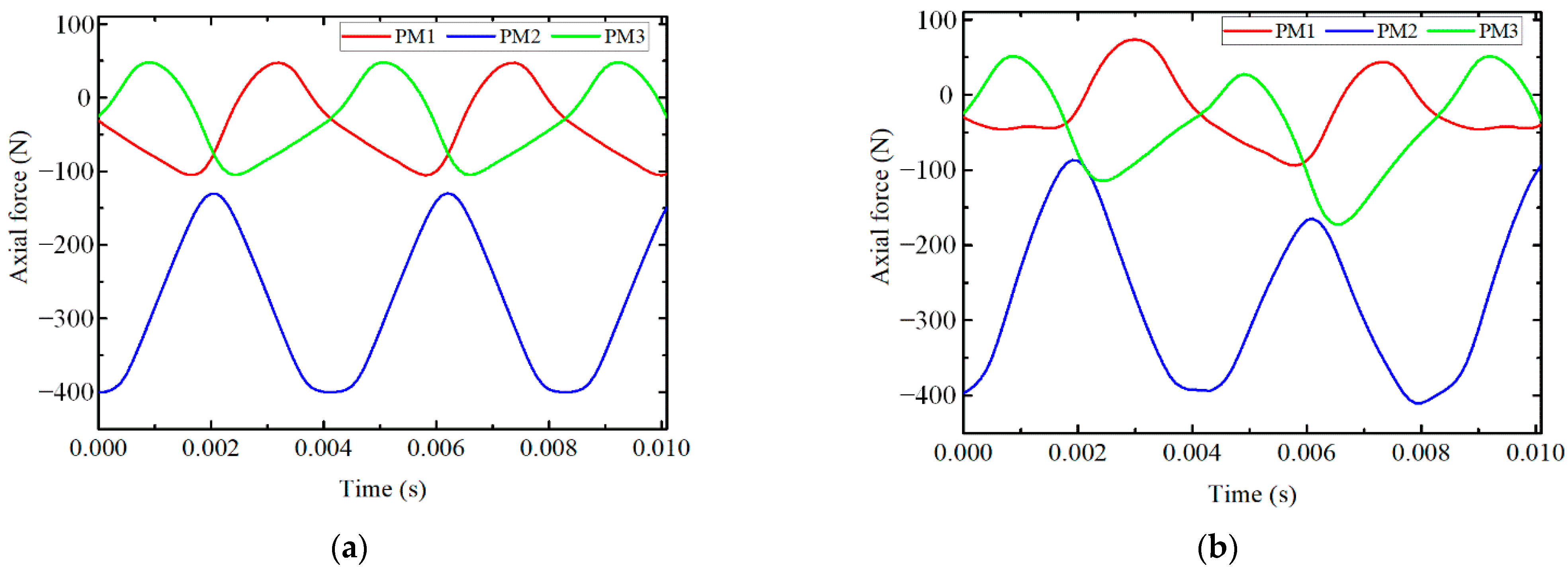
3.2. Study of Axial Force

Due to a large number of planar PMs, the rotor of AFPM machines bears a strong attracted force towards stator when working. The attracted force may lead to distortion and tilt of the rotor, which will affect the performance of the machine. The axial force on the axial rotor on one side is calculated when the air-gap depth is 1 mm in the ARFPM machine.
Figure 11a,b show the axial forces on three PM segments per pole with and without load, respectively. Due to different magnetization directions, the PM segments bear different axial forces. The negative sign means the axial force points towards the stator. The axial force on the axial magnetized PM segment is the largest, which means the Halbach-array PMs can reduce the axial force on axial rotors. Figure 11b shows that there is an axial electromagnetic force when the ARFPM machine works on load. It affects the amplitude of the axial force on each PM, but the maximum axial force on a single PM segment is still near 400 N.
Figure 12 shows the total axial force applied on an axial rotor. When the machine works without load, the axial force fluctuates from 2935 N to 2940 N. The axial electromagnetic force on the axial rotor makes the fluctuation larger when the machine works on load. The maximum axial force on the axial rotor is near 2947 N. Thus, the deformation of the axial rotor and single PM segment is analyzed. Considering the worst condition, the axial forces applied on the PM segment and axial rotor are set as 400 N and 2947 N, respectively. Figure 13 shows the deformation of the single PM segment and axial rotor during operation.
As shown in Figure 13a, the deformation of the PM segment is so slight that it can be neglected when the axial force is 400 N. However, Figure 13b shows that the deformation of the axial rotor is relatively serious when the total axial force is 2947 N. The axial rotor will bend toward the stator, which will affect the performances of the machine and even cause faults. The condition is the most serious at the outer ring when the inner ring is fixed with a shaft. In the AFRPM machine, the radial rotor supports the outer rings of the two axial rotors and is fixed with them, so the deformation can be prevented by the radial rotor. This can avoid the faults caused by deformation. In addition, the axial force acting on two axial rotors can be balanced. Thus, the whole rotary component is zero, which prevents the large axial force causing axial rotor tilting.

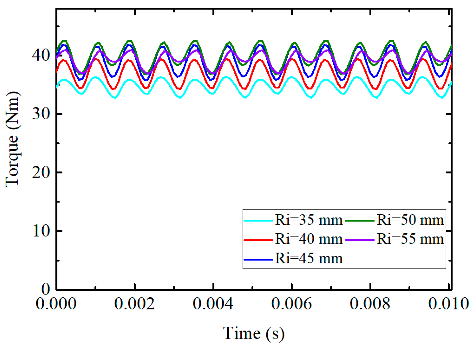
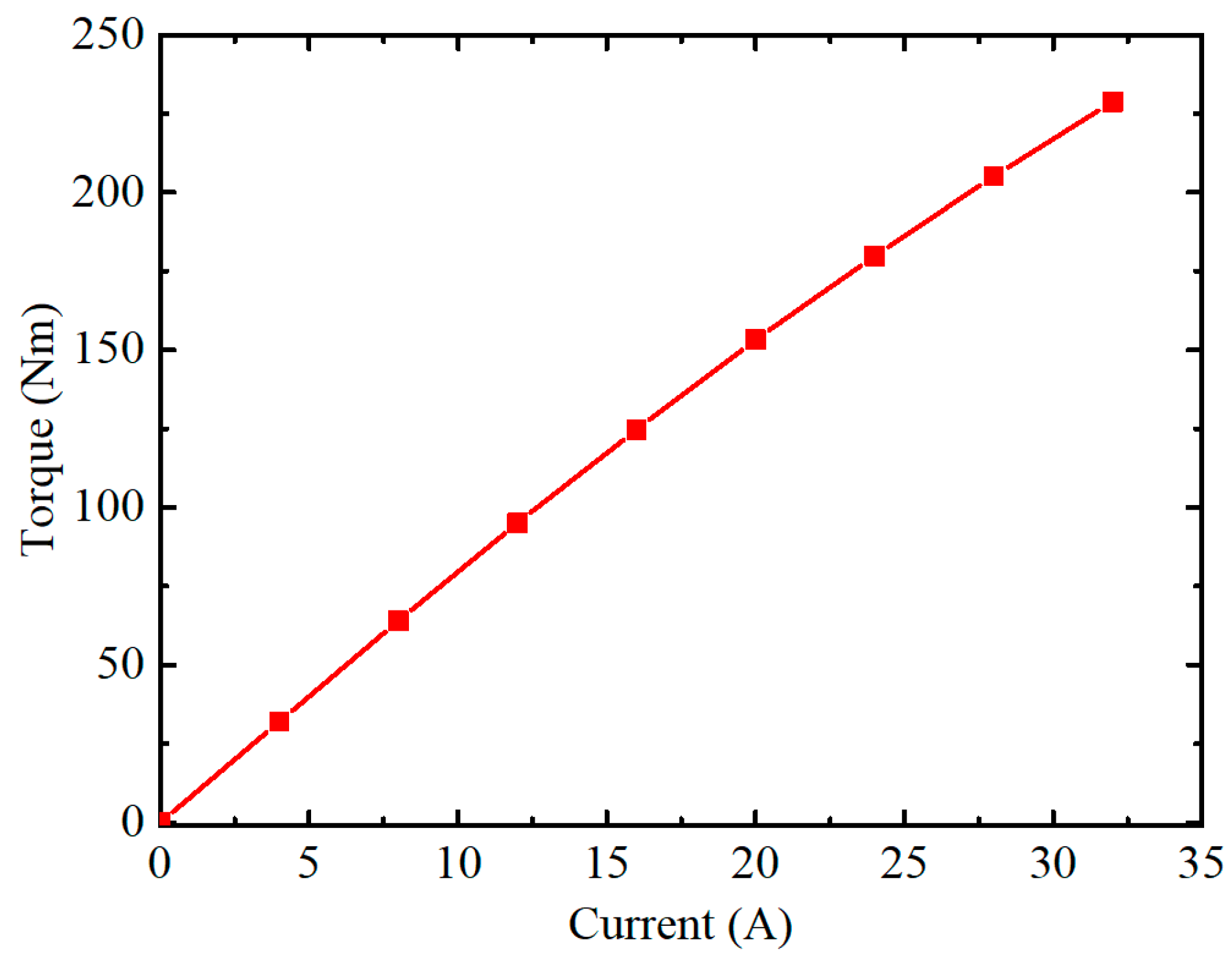
3.3. Study of Electromagnetic Torque

The goal of the study on electromagnetic torque is to find the largest torque with the same outer diameter. As shown in (5), the electromagnetic torque is related to the inner diameter in addition to the depth of the air gap, but the relationship is not monotonous. Hence, the electromagnetic torque at different inner diameters is calculated.
Figure 14 shows the electromagnetic torque of the ARFPM machine with different inner radius. According to the comparison, the electromagnetic torque will be reduced when the inner radius is too small or too large. The ARFPM machine can obtain the largest electromagnetic torque when the inner radius is 50 mm. The average electromagnetic torque is 39.93 Nm.
With the chosen dimensions, the torque characteristic of the ARFPM machine is studied. Figure 15 shows the average torque versus root mean square (RMS) current. The average torque is nearly proportional to the phase current, although the increase of torque becomes a little slow when the current is more than 16 A. It shows that the increase of current will not lead to serious saturation in the machine, which means that the ARFPM machine has a strong overload capability.

4. Comparative Analysis of ARFPM Machine

In order to verify the performances of the proposed ARFPM machine, it is compared with a conventional AFPM machine and a RFPM machine. Aimed at a fair comparison, some dimensions, such as outer and inner diameters and axial length, of the three machines should be the same, although these dimensions may not be optimal for another two machines. In addition, toroidal windings are also adopted in the AFPM machine and RFPM machine. The topologies of the AFPM machine and the RFPM machine are shown in Figure 16. The dimensions of the three machines are listed in Table 1.
The three machines are compared through FEA. The magnetic flux path of the RFPM machine is in a 2D plane, so a 2D finite element model is enough to simulate the machine. As for the AFPM machine and the ARFPM machine, 3D FEA has to be conducted due to the 3D magnetic flux. The mesh structures for the three machine models are shown in Figure 17. This shows that the RFPM machine model has the minimum meshes. The simulation results of the three machines are shown in Figure 18. The magnetic flux density at the edge of the slot and tooth tips is large, which results in local saturation. Moreover, Figure 18 shows that the AFRPM machine has the highest utilization of material.

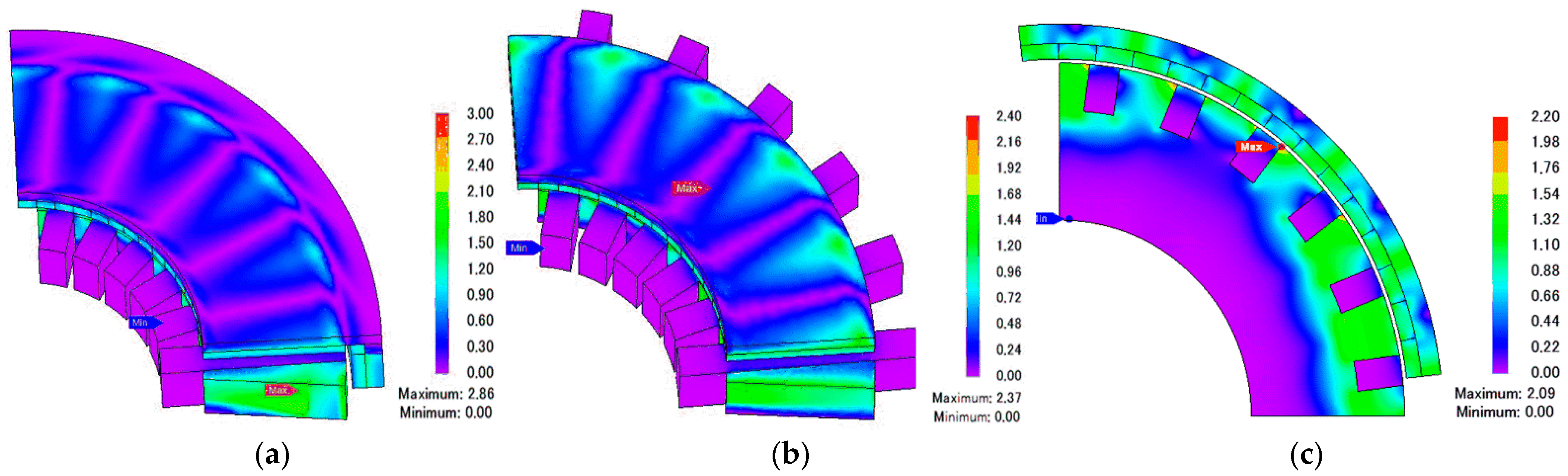
4.1. Air-Gap Magnetic Flux Density

According to the analysis above, the air-gap magnetic flux density is one of the factors of magnetic flux. In different topologies, the direction of active air-gap magnetic flux density is different. In particular, the active air-gap flux density in the ARFPM machine has to be considered in two directions separately. The normal components of no-load air-gap magnetic flux density in the three machines are compared in Figure 19.
As seen from Figure 19, the normal components of air-gap magnetic flux density in different machines are very similar, which means that it has nothing to do with the direction. The waveform of the air-gap magnetic flux density is determined by the pole-slot configuration, PM arrangement, and depth of air gap. Hence, the normal component of air-gap magnetic flux density is not the key factor causing different performances in the three machines.

4.2. No-Load Back EMF

No-load Back EMF is affected by the air-gap magnetic flux density and dimensions. The waveforms of the normal air-gap flux density in the three machines are the same, but the cross-sectional areas that air-gap magnetic flux flows through are different, resulting in different back EMF in the ARFPM machine, AFPM machine, and RFPM machine. The no-load back EMFs of the three machines are calculated when the rotary speed is 600 rpm. The comparison is shown in Figure 20.
Due to the different air-gap areas, the ARFPM machine has the largest back EMF, while the RFPM machine has the smallest back EMF. It shows the same rules as analyzed in Section 2. However, the back EMF of the ARFPM machine is distorted most seriously. Figure 20b shows the fast Fourier transform of the back EMF. The back EMF in the ARFPM machine contains the most harmonics. The total harmonic distortion (THD) of the back EMF in the ARFPM machine is 9.47%, while those in the AFPM machine and RFPM machine are 1.32% and 1.90%, respectively. The largest harmonic of back EMF in the ARFPM machine is the third harmonic, which may be caused by the flux leakage at the vertexes and edges of the stator. In fact, the third harmonic can be ignored due to the star connection of the windings, so the distortion will not affect the operation of the ARFPM machine obviously.

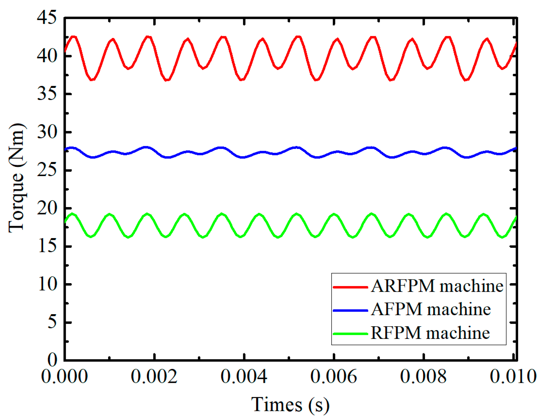
4.3. Electromagnetic Torque

Electromagnetic torque is one of the most important performance factors in a machine. A machine with large electromagnetic torque does not need planetary gears when it is applied in a propulsion system, which reduces the manufacture and maintenance cost. Due to different structures, the proposed ARFPM machine, AFPM machine, and RFPM machine have different electromagnetic torques. The electromagnetic torques of the three machines are calculated when the current density is 5 A/mm2.
Figure 21 compares the electromagnetic torques of the three machines. With the same current density, the ARFPM machine has the largest electromagnetic torque. The average torque of the ARFPM machine is 39.93 Nm, while those of the AFPM machine and the RFPM machine are 27.33 Nm and 17.74 Nm, respectively. This means the ARFPM machine has the highest torque density because the volumes of the three machines are the same.
However, the torque ripple of the ARFPM machine is 14.3%, which is not the smallest. The AFPM machine has the minimum torque ripple, which is only 5.0%, while that of the RFPM machine is 17.8%. The result shows that the radial air gap may lead to a larger torque ripple than the axial air gap. Thus, due to the combination of axial rotors and a radial rotor, the torque ripple of the ARFPM machine is larger than that of the AFPM machine and smaller than that of the RFPM machine.

4.4. Cogging Torque

Cogging torque is one of the reasons for the torque ripple. It is mainly caused by the interaction between the PMs and stator teeth, so it is determined by the structure of the machine. The cogging torque can be reduced by skew PMs and teeth in many machines [30,31]. In the paper, all the stator slots are rectangular, so the RFPM machine has rectangular teeth, and the AFPM machine has triangular skew fan-shaped teeth. The ARFPM machine has both kinds of teeth. The cogging torques of the three machines are compared in Figure 22.
Due to the same pole-slot configuration, the cogging torque of the three machines has the same period. Equipped with triangular skew fan-shaped teeth, the AFPM machine has smaller cogging torque than the RFPM machine. The smallest cogging torque is 0.83 Nm, while the cogging torque of the RFPM machine is 3.18 Nm. The ARFPM machine has three rotors, so the cogging torque is the sum of those of the three rotors. It has the largest cogging torque, which is 3.60 Nm. The large cogging torque leads to a relatively large torque ripple, but the expense is acceptable considering the increase of electromagnetic torque.
The performance comparison of the ARFPM machine, AFPM machine, and RFPM machine is summarized in Table 2. Compared with the AFPM machine and the RFPM machine, the ARFPM machine improves the electromagnetic torque and back EMF at the same volume and current density with the expense of relatively large number of PMs, harmonics, and cogging torque. The torque-to-PM volume ratios of the three machines are listed in Table 2. The ratio of the ARFPM machine is the smallest, but the differences are not very large compared with the increase of torque. Considering the aim to increase the torque density of the machine, this drawback is not very critical. In addition, The main part of harmonics in the back EMF is the third-order harmonic, so the THD can be reduced through the star connection of windings. The comparison shows that the ARFPM machine is very suitable for direct-drive systems such as industrial robotics.

5. Conclusions

In this paper, a novel ARFPM machine with Halbach-array PMs was designed and analyzed. A parametric study was performed to optimize the geometry of the machine for optimal performances. A radial rotor was applied in the ARFPM machine to balance the large axial force and prevent the tilt and deformation of axial rotors. Compared with conventional arranged PMs, Halbach-array PMs can make the back EMF contain fewer fifth harmonics, which is only 2.03% of the fundamental component. The electromagnetic torque of the ARFPM machine achieved 39.93 Nm. Also, it had a strong overload capability.
Then, a comparative analysis was conducted. The proposed ARFPM machine was compared to an AFPM machine and a RFPM machine under the same volume. The back EMF amplitude of the proposed ARFPM machine was the largest. Moreover, the major harmonic in back EMF can be eliminated by the star connection of three-phase windings. The cogging torque of the ARFPM machine was the largest. This led to a relatively large torque ripple, which was smaller than that of the RFPM and larger than that of the AFPM. Thus, the cogging torque has to be optimized in future work. In addition, the comparison also showed that the proposed ARFPM machine had the largest electromagnetic torque when the current density was the same. This proved that the proposed ARFPM machine with Halbach-array PMs can be applied in direct-drive systems.

Author Contributions

The work presented in this paper is the output of the research projects undertaken by C.L. In specific, all authors developed the topic. R.H. carried out the simulation and comparison, analyzed the results, and wrote the paper. Z.S. and H.Z. gave some suggestions on the calculation process and revised the manuscript. C.L. supervised all the work. All authors have read and agreed to the published version of the manuscript.

Funding

This work was supported in part by a grant (Project No. 52077186 and 51677159) from the Natural Science Foundation of China (NSFC), China; in part by a grant (Project No. JCYJ20180307123918658) from the Science Technology and Innovation Committee of Shenzhen Municipality, Shenzhen, China; in part by a grant (Project No. ITP/027/19AP) from the Innovation and Technology Commission, Hong Kong SAR; and in part by Strategic Research Grant and Applied Research Grant (Project No. CityU11218519, CityU11217520 and ARG9667214) from the City University of Hong Kong, Hong Kong SAR.

Institutional Review Board Statement

Not applicable.

Informed Consent Statement

Not applicable.

Conflicts of Interest

The authors declare no conflict of interest.

References

  1. Zhao, H.; Liu, C.; Song, Z.; Wang, W. Analytical Modeling of a Double-Rotor Multiwinding Machine for Hybrid Aircraft Propulsion. IEEE Trans. Transp. Electrif. 2020, 6, 1537–1550. [Google Scholar] [CrossRef]
  2. Wang, D.; Peng, C.; Xue, D.; Zhang, D.; Wang, X. Performance Assessment and Comparative Study of a Permanent Magnet Machine with Axial Flux Regulator. IEEE Trans. Energy Convers. 2019, 34, 1522–1531. [Google Scholar] [CrossRef]
  3. Yu, J.; Liu, C.; Song, Z.; Zhao, H. Permeance and Inductance Modeling of a Double-Stator Hybrid-Excited Flux-Switching Permanent-Magnet Machine. IEEE Trans. Transp. Electrif. 2020, 6, 1134–1145. [Google Scholar] [CrossRef]
  4. Liu, C.; Chau, K.T.; Lee, C.H.T.; Song, Z. A Critical Review of Advanced Electric Machines and Control Strategies for Electric Vehicles. Inst. Electr. Electron. Eng. 2020, 109, 1004–1028. [Google Scholar] [CrossRef]
  5. Tong, C.; Song, Z.; Bai, J.; Liu, J.; Zheng, P. Analytical Investigation of the Magnetic-Field Distribution in an Axial Magnetic-Field-Modulated Brushless Double-Rotor Machine. Energies 2016, 9, 589. [Google Scholar] [CrossRef] [Green Version]
  6. Song, Z.; Liu, C.; Zhao, H. Investigation on Magnetic Force of a Flux-Modulated Double-Rotor Permanent Magnet Synchronous Machine for Hybrid Electric Vehicle. IEEE Trans. Transp. Electrif. 2019, 5, 1383–1394. [Google Scholar] [CrossRef]
  7. Aydin, M.; Surong, H.; Lipo, T.A. Torque quality and comparison of internal and external rotor axial flux surface-magnet disc machines. IEEE Trans. Ind. Electron. 2006, 53, 822–830. [Google Scholar] [CrossRef]
  8. Khatab, M.F.H.; Zhu, Z.Q.; Li, H.Y.; Liu, Y. Comparative study of novel axial flux magnetically geared and conventional axial flux permanent magnet machines. CES Trans. Electr. Mach. Syst. 2018, 2, 392–398. [Google Scholar] [CrossRef]
  9. Mahmoudi, A.; Kahourzade, S.; Rahim, N.A.; Hew, W.P.; Uddin, M.N. Design, Analysis, and Prototyping of a Novel-Structured Solid-Rotor-Ringed Line-Start Axial-Flux Permanent-Magnet Motor. IEEE Trans. Ind. Electron. 2014, 61, 1722–1734. [Google Scholar] [CrossRef]
  10. Trong Duy, N.; King-Jet, T.; Shao, Z.; Hoan Thong, N. A Novel Axial Flux Permanent-Magnet Machine for Flywheel Energy Storage System: Design and Analysis. IEEE Trans. Ind. Electron. 2011, 58, 3784–3794. [Google Scholar] [CrossRef]
  11. Fawzal, A.S.; Cirstea, R.M.; Gyftakis, K.N.; Woolmer, T.J.; Dickison, M.; Blundell, M. Fan Performance Analysis for Rotor Cooling of Axial Flux Permanent Magnet Machines. IEEE Trans. Ind. Appl. 2017, 53, 3295–3304. [Google Scholar] [CrossRef]
  12. Dwivedi, A.; kumar Singh, S.; Srivastava, R.K. Analysis and Performance Evaluation of Axial Flux Permanent Magnet Motors. IEEE Trans. Ind. Appl. 2018, 54, 1765–1772. [Google Scholar] [CrossRef]
  13. Zhang, R.; Li, J.; Qu, R.; Li, D. Analysis and Design of Triple-Rotor Axial-Flux Spoke-Array Vernier Permanent Magnet Machines. IEEE Trans. Ind. Appl. 2018, 54, 244–253. [Google Scholar] [CrossRef]
  14. Geng, W.W.; Zhang, Z.R. Analysis and Implementation of New Ironless Stator Axial-Flux Permanent Magnet Machine with Concentrated Nonoverlapping Windings. IEEE Trans. Energy Convers. 2018, 33, 1274–1284. [Google Scholar] [CrossRef]
  15. Vansompel, H.; Sergeant, P.; Dupre, L.; Bossche, A. A Combined Wye-Delta Connection to Increase the Performance of Axial-Flux PM Machines with Concentrated Windings. IEEE Trans. Energy Convers. 2012, 27, 403–410. [Google Scholar] [CrossRef]
  16. Pranjic, F.; Virtic, P. Designing Rotor Disks of a Coreless Axial Flux Permanent Magnet Machines by Using Simplified FEM and an Approximation Method. IEEE Trans. Energy Convers. 2020, 35, 1505–1512. [Google Scholar] [CrossRef]
  17. Kim, J.; Choi, W.; Sarlioglu, B. Closed-form Solution for Axial Flux Permanent Magnet Machines with a Traction Application Study. IEEE Trans. Ind. Appl. 2015, 52, 1775–1784. [Google Scholar] [CrossRef]
  18. Virtic, P.; Vrazic, M.; Papa, G. Design of an Axial Flux Permanent Magnet Synchronous Machine Using Analytical Method and Evolutionary Optimization. IEEE Trans. Energy Convers. 2016, 31, 150–158. [Google Scholar] [CrossRef]
  19. Di Gerlando, A.; Foglia, G.M.; Iacchetti, M.F.; Perini, R. Parasitic Currents in Stray Paths of Some Topologies of YASA AFPM Machines: Trend with Machine Size. IEEE Trans. Ind. Electron. 2016, 63, 2746–2756. [Google Scholar] [CrossRef] [Green Version]
  20. Winterborne, D.; Stannard, N.; Sjoberg, L.; Atkinson, G. An Air-Cooled YASA Motor for in-Wheel Electric Vehicle Applications. IEEE Trans. Ind. Appl. 2020, 56, 6448–6455. [Google Scholar] [CrossRef]
  21. Taran, N.; Rallabandi, V.; Heins, G.; Ionel, D.M. Coreless and Conventional Axial Flux Permanent Magnet Motors for Solar Cars. IEEE Trans. Ind. Appl. 2018, 54, 5907–5917. [Google Scholar] [CrossRef]
  22. Mirimani, S.M.; Vahedi, A.; Marignetti, F.; de Santis, E. Static Eccentricity Fault Detection in Single-Stator–Single-Rotor Axial-Flux Permanent-Magnet Machines. IEEE Trans. Ind. Appl. 2012, 48, 1838–1845. [Google Scholar] [CrossRef]
  23. Ajily, E.; Ardebili, M.; Abbaszadeh, K. Magnet Defect and Rotor Eccentricity Modeling in Axial-Flux Permanent-Magnet Machines via 3-D Field Reconstruction Method. IEEE Trans. Energy Convers. 2016, 31, 486–495. [Google Scholar] [CrossRef]
  24. Aydin, M.; Gulec, M. A New Coreless Axial Flux Interior Permanent Magnet Synchronous Motor with Sinusoidal Rotor Segments. IEEE Trans. Magn. 2016, 52, 1–4. [Google Scholar] [CrossRef]
  25. De Donato, G.; Capponi, F.G.; Rivellini, A.; Caricchi, F. Integer-Slot vs Fractional-Slot Concentrated-Winding Axial-Flux Permanent Magnet Machines: Comparative Design, FEA and Experimental Tests. In Proceedings of the 2011 IEEE Energy Conversion Congress and Exposition, Phoenix, AZ, USA, 17–22 September 2011; pp. 3120–3127. [Google Scholar]
  26. De Donato, G.; Giulii Capponi, F.; Caricchi, F. Fractional-Slot Concentrated-Winding Axial-Flux Permanent-Magnet Machine with Core-Wound Coils. IEEE Trans. Ind. Appl. 2012, 48, 630–641. [Google Scholar] [CrossRef]
  27. Song, Z.; Liu, C.; Feng, K.; Zhao, H.; Yu, J. Field Prediction and Validation of a Slotless Segmented-Halbach Permanent Magnet Synchronous Machine for More Electric Aircraft. IEEE Trans. Transp. Electrif. 2020, 6, 1577–1591. [Google Scholar] [CrossRef]
  28. Jin, P.; Yuan, Y.; Xu, Q.; Fang, S.; Lin, H.; Ho, S.L. Analysis of Axial-Flux Halbach Permanent-Magnet Machine. IEEE Trans. Magn. 2015, 51, 1–4. [Google Scholar] [CrossRef]
  29. Tang, R. Modern Permanent Magnet Machines: Theory and Design, 1st ed.; China Machine Press: Beijing, China, 2015; Volume 9. [Google Scholar]
  30. Xiao, L.; Li, J.; Qu, R.; Lu, Y.; Zhang, R.; Li, D. Cogging Torque Analysis and Minimization of Axial Flux PM Machines with Combined Rectangle-Shaped Magnet. IEEE Trans. Ind. Appl. 2017, 53, 1018–1027. [Google Scholar] [CrossRef]
  31. Wanjiku, J.; Khan, M.A.; Barendse, P.S.; Pillay, P. Influence of Slot Openings and Tooth Profile on Cogging Torque in Axial-Flux PM Machines. IEEE Trans. Ind. Electron. 2015, 62, 7578–7589. [Google Scholar] [CrossRef]
Figure 1. Topology of the axial-radial flux permanent magnet (ARFPM) machine. 1—Stator core, 2—Windings, 3—Radial PMs, 4—Radial rotor back iron, 5—Axial PMs, 6—Axial rotor back iron.
Energies 14 03639 g001
Figure 2. Toroidal windings in the ARFPM machine.
Energies 14 03639 g002
Figure 3. Halbach-array permanent magnets (PMs) in the ARFPM machine: (a) magnetization pattern; (b) magnetization distribution.
Energies 14 03639 g003
Figure 4. Magnetic flux paths in the ARFPM machine.
Energies 14 03639 g004
Figure 5. Three-dimensional finite element analysis (3D FEA) model of ARFPM machine.
Energies 14 03639 g005
Figure 6. Normal air-gap magnetic flux density produced by PMs: (a) conventional PMs; (b) Halbach-array PMs.
Energies 14 03639 g006
Figure 7. Tangential air-gap magnetic flux density produced by PMs: (a) conventional PMs; (b) Halbach-array PMs.
Energies 14 03639 g007
Figure 8. Back electromotive force (EMF) with different PM arrangement: (a) back EMF of U-phase; (b) fast Fourier transform (FFT) of back EMF.
Energies 14 03639 g008
Figure 9. Normal air-gap magnetic flux density. (a) Axial air-gap flux density, (b) radial air-gap flux density.
Energies 14 03639 g009
Figure 10. Back EMF with different air-gap depths: (a) waveforms of back EMFs; (b) FFT of the back EMF.
Energies 14 03639 g010
Figure 11. Axial forces on different PMs: (a) axial forces without load; (b) axial forces with load.
Energies 14 03639 g011
Figure 12. Attracted force on one axial rotor.
Energies 14 03639 g012
Figure 13. Deformation of PM and axial rotor under maximum axial force: (a) deformation of PM; (b) deformation of the axial rotor.
Energies 14 03639 g013
Figure 14. Electromagnetic torque.
Energies 14 03639 g014
Figure 15. Variation of torque versus current.
Energies 14 03639 g015
Figure 16. Topologies of two machines: 1—Stator core, 2—Windings, 3—Radial PMs, 4—Radial rotor back iron, 5—Axial PMs, 6—Axial rotor back iron: (a) AFPM machine; (b) RFPM machine.
Energies 14 03639 g016
Figure 17. Mesh structures of three machines: (a) ARFPM machine; (b) AFPM machine; (c) RFPM machine.
Energies 14 03639 g017
Figure 18. Magnetic flux density distribution of three machines: (a) ARFPM machine; (b) AFPM machine; (c) RFPM machine.
Energies 14 03639 g018
Figure 19. Comparison of no-load air-gap magnetic flux density.
Energies 14 03639 g019
Figure 20. Comparison of no-load back EMFs: (a) waveform of no-load back EMF; (b) FFT of no-load back EMF.
Energies 14 03639 g020
Figure 21. Comparison of electromagnetic torque of three machines.
Energies 14 03639 g021
Figure 22. Comparison of cogging torque of three machines.
Energies 14 03639 g022
Table 1. Specifications of three machines.
ParameterARFPM MachineAFPM MachineRFPM Machine
Pole pairs101010
Slot number242424
Outer diameter of the machine200 mm200 mm (include length of ends)200 mm
Inner diameter of the machine100 mm100 mm100 mm
Width of slot7.86 mm7.86 mm7.86 mm
Depth of slot12 mm12 mm12 mm
Thickness of PM4 mm4 mm4 mm
Axial length of the machine60 mm60 mm60 mm (include length of ends)
Air-gap depth1 mm1 mm1 mm
Turns in every slot656565
Current density5 A/mm25 A/mm25 A/mm2
Rotary speed600 rpm600 rpm600 rpm
Table 2. Performances of the three machines.
PerformanceARFPM MachineAFPM MachineRFPM Machine
Back EMF256 V161 V105 V
THD of back EMF9.47%1.32%1.90%
Electromagnetic torque39.93 Nm27.33 Nm17.74 Nm
Torque-to-PM volume170.47 Nm/L194.18 Nm/L189.75 Nm/L
Torque ripple14.3%5.0%17.8%
Cogging torque3.60 Nm0.83 Nm3.18 Nm
Current density5 A/mm25 A/mm25 A/mm2
Publisher’s Note: MDPI stays neutral with regard to jurisdictional claims in published maps and institutional affiliations.

