Article

Accounting for Slot Harmonics and Nonsinusoidal Unbalanced Voltage Supply in High-Speed Solid-Rotor Induction Motor Using Complex Multi-Harmonic Finite Element Analysis

Faculty of Electrical Engineering, Automatic Control and Informatics, Opole University of Technology, ul. Proszkowska 76, 45-758 Opole, Poland
*
Author to whom correspondence should be addressed.
Energies 2021, 14(17), 5404; https://doi.org/10.3390/en14175404
Submission received: 19 July 2021 / Revised: 24 August 2021 / Accepted: 27 August 2021 / Published: 30 August 2021
(This article belongs to the Special Issue Performance of Induction Machines)

Abstract

:
Solid rotor induction machines are still used in high-speed systems. A two-dimensional field-circuit model based on the finite element method and the complex magnetic vector potential has been shown as a very time-effective tool in the analysis of their steady states compared to time-domain models. This continuation work presents a validated computational algorithm that enables the inclusion of the nonsinusoidal and/or asymmetrical voltage supply in the multi-harmonic field-circuit model of these machines that was presented in the previous works by the authors. The extended model accounts for both spatial harmonics due to slotting and/or winding distribution and the time-harmonics due to voltage waveform. The applicability range of the model therefore increases to cases when the machine is supplied with a nonsinusoidal three-phase system of voltages with symmetry or asymmetry that can be decomposed into three symmetrical components. Its short execution time characteristic allows for much more insightful design studies of the contribution of voltage supply- and slotting-related harmonics to the overall efficiency of the machine than is possible with the time-consuming time-domain models. The proposed computational framework has never been presented in the literature. The model is verified positively by the comprehensive time-domain model. It is especially useful in design studies on solid rotor induction motors related to the optimisation of the efficiency of induction motor-based drive systems.

1. Introduction

Despite the growing popularity of permanent magnet electric machines, induction motors still remain the main components of industrial electric drives. This is due to the simplicity of construction, reliability and the development of static converters that allow the shaping of static characteristics and dynamic parameters of the drive system. Among the various designs, the induction machine with solid rotor deserves special attention, being one of the simplest and oldest AC electric machines, although requiring entirely different design routines that have been in development for nearly a century [1,2,3,4,5]. The mechanical properties of the solid rotor, as well as their resistance to aggressive chemical compounds, are incomparable to any other structure, which makes them a suitable source of drive-in applications requiring high or very high rotational speed such as those shown in [6,7,8,9,10,11,12,13].
The analysis of the properties and design of the discussed machine is still considered a difficult task, mainly because of the very complex electromagnetic phenomena occurring in the solid rotor. The only method that allows for the overall effect of these phenomena to be taken into account is to utilize a non-linear three-dimensional numerical model formulated in the time domain. Unfortunately, as the calculations would take a long time, this method is difficult to apply in practice. For this reason, alternative approaches have been developed which, in principle, can be divided into two groups: methods based on the analytical solution of the field problem in the solid rotor presented in [14,15,16,17,18], and methods utilizing the two-dimensional numerical models formulated as time-domain or frequency-domain models used in works [7,9,10,11,19,20,21].
The basic problem related to the analysis of high-speed induction machines with solid rotors using two-dimensional numerical models formulated in the time domain is a very long computation time resulting from a significant ratio of the electromagnetic time constant of the machine to the supply voltage period. In the case where the subjects of consideration are the steady states of the machine, the computation time can be shortened by applying special modifications of the model formulated in the time-domain, such as: elimination of the DC flux linkage in [22], elimination of the DC current at each step in [23], transient magnetic solution initialized with proper initial values [24] or initial current extraction in [19].
A very promising alternative to the models formulated in the time domain is the use of modified time-harmonic models, such as, for example, the multi-harmonic field model with a strong coupling, which takes into account the influence of the spatial harmonics due to the slotting or winding distribution on the losses in the solid rotor and the value of the developed electromagnetic torque [25,26,27,28,29,30,31]. In these models these effects can be accounted for using the modified slip
s = 1 ν 1 s
where ν is the ordinal number of spatial harmonic ( ν ) and s is the fundamental slip.
As shown in the works [30,31], with the appropriate formulation of the stator–rotor coupling scheme and the method of modelling materials non-linearity, it is possible to obtain high accuracy of the results of steady-state calculations in a very short time of model execution. This is because relatively coarse mesh densities are sufficient for the representation of the most important air gap magnetic field harmonics.
In this moment, the application of this type of model was limited to the case of the symmetrical sinusoidal voltage supply of the stator winding. In the present work, the concept of multi-harmonic effective magnetic permeability proposed in [31] was used to develop an original approach that allows for taking into account the nonsinusoidal voltage supply waveforms (that appear, for example, when supplying the machine through a quasi-square voltage inverter) in a multi-harmonic model of a solid rotor induction machine. It is shown that the steady-state time-harmonic model with only a few dominating time-harmonics of the magnetic field attributed to the voltage supply provides solutions very similar to ones obtained from a time-demanding time-domain solution. This is in terms of the magnitude and phase relationships of the waveforms as well as the computed torques and power losses. The execution time of the former is however only a fraction of that of the latter. Moreover, the model is demonstrated to work correctly in cases where the voltage supply exposes noticeable asymmetry that appears during inverter fault conditions. The above means that in the mathematical sense the model is capable of accounting for the space-harmonics and the time-harmonics that come from the power supply, but not from the motional effects which are more important in the squirrel cage machines. It is thus most suitable to analyze induction motors with solid rotors. To the best of the authors’ knowledge such a model has not been proposed until this moment.
The basic operating characteristics of the machine were calculated for four different supply voltage waveforms, and then compared with the results of calculations obtained via the comprehensive model formulated in the time domain which in the steady-state condition considers the whole spectrum of magnetic field harmonics. Original contributions of this work include:
-
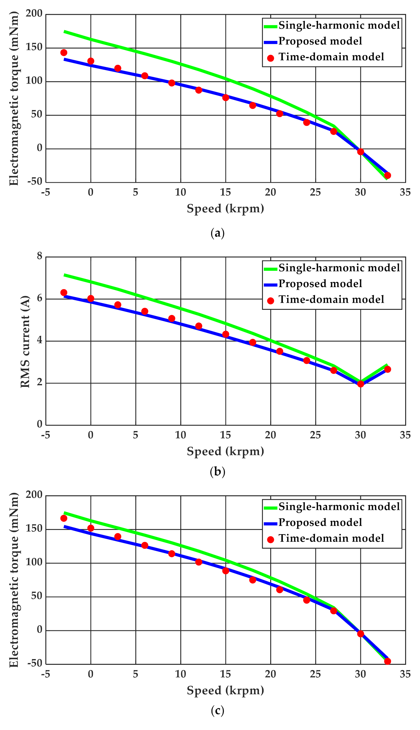
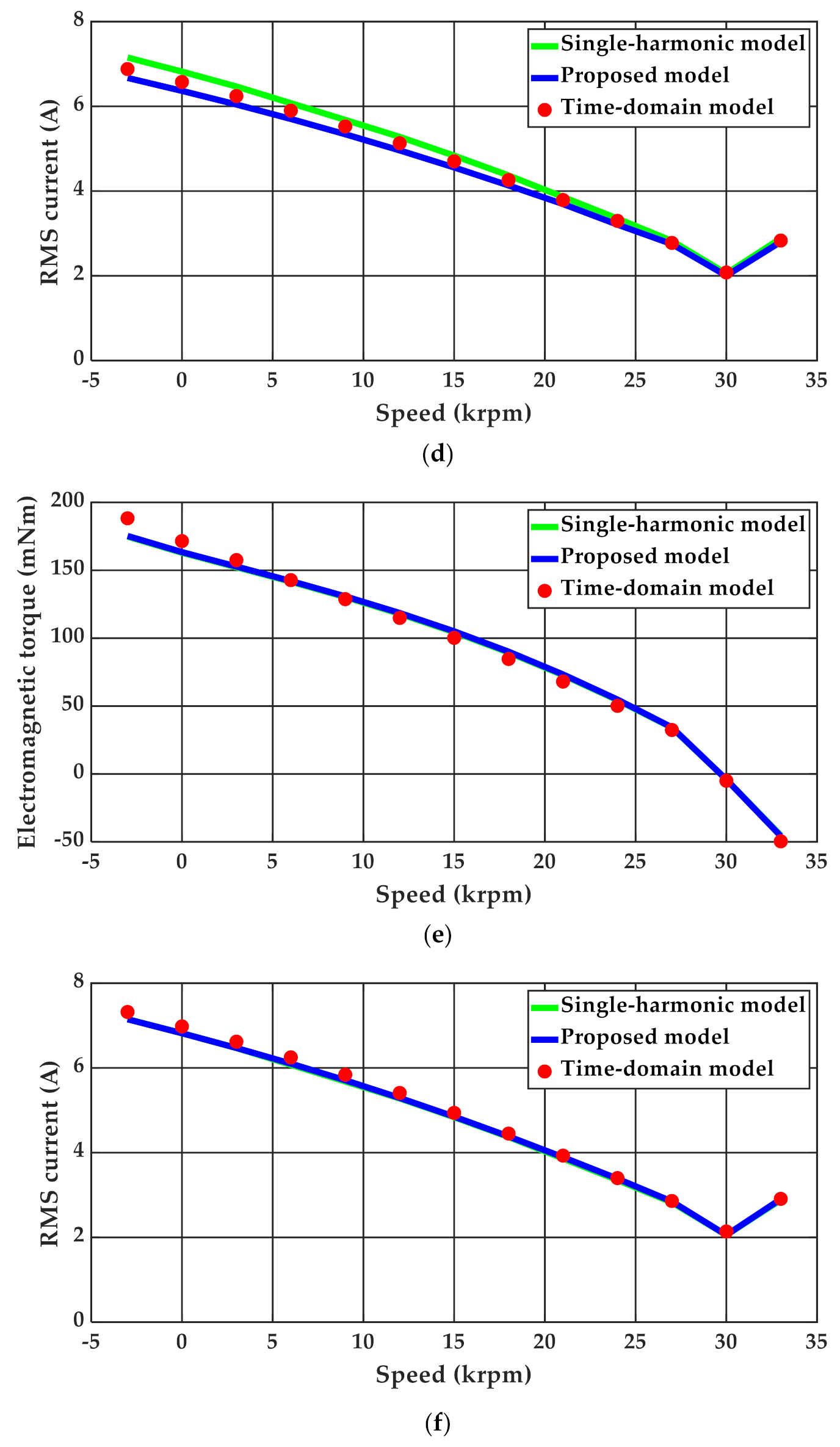
development, implementation and validation of a cost-effective computational algorithm for nonlinear steady-state analysis of solid-rotor induction motors with an accuracy characteristic comparable to that of the comprehensive time-domain model
-
determination of the torque and power dissipation in the rotor as sets of separated components associated with the time- and space-harmonics of the magnetic field allowing for a more detailed analysis of the impact of stator slotting and power supply harmonics on machine efficiency.

2. Mathematical Model

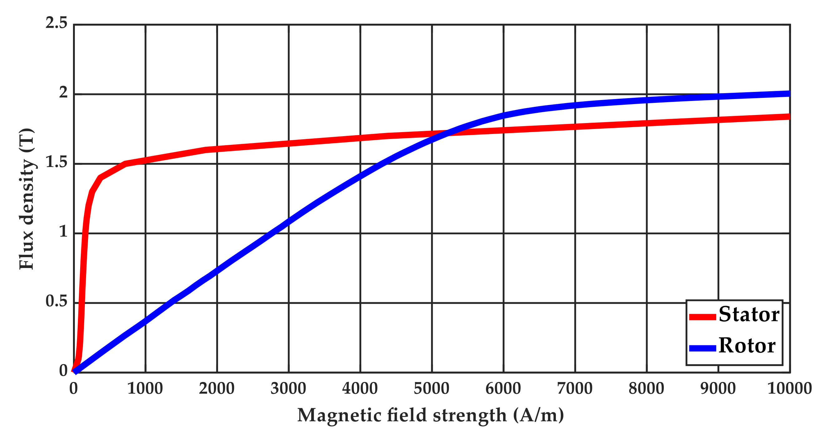
2.1. Analysed Machine

The subject of research presented in the present work is a high-speed machine with a homogeneous solid rotor, already analysed in the previous works by the authors [30,31]. The basic data of the converter and the materials’ magnetization characteristics of the stator and rotor area adopted for the calculations are shown in Table 1 and Figure 1 and Figure 2.
For the sake of simplicity, the influence of the rotor end-effects and losses in the stator package, and those due to the hysteresis in the rotor area, have been neglected. The influence of the rotor end-effects can be taken into account by applying the so-called rotor end-effect coefficient, that can be calculated analytically or numerically as shown in [21]. Taking into account the above losses, however, will require separate research, which is the authors’ aim for the future. It should be noticed that the above assumptions are necessary from the point of view of the possibility to validate the proposed approach by the comprehensive time-domain model. It is also worth noticing that due to these assumptions the obtained results will be very hard or even impossible to verify on the experimental test-stand.

2.2. Reference Time-Stepping Model

All the results of the calculations presented in this work using the proposed approach were compared with the results of calculations using the complete model formulated in the time domain. The equations for such a model after discretisation via the Galerkin procedure and the implicit Euler method take the form of [31]:
S μ D C + G t 1 D T K T l z K D t 1 K R + L t 1 K T n φ i S n = G t 1 0 l z K D t 1 K L t 1 K T n 1 φ i S n 1 + + 0 K e S n 1 ,
where: S—reluctivity matrix, G—conductivity matrix, D—matrix describing the winding, K—matrix describing the winding connection method, R—winding resistance matrix, L—winding leakage inductivity matrix, ∆t—time-integration step, φ—vector of nodal values of the vector magnetic potential, i S —vector of instantaneous values of the stator loop currents, e S —vector of the instantaneous supply voltages in the stator winding, μ D C —DC magnetic permeability. The rotational movement was modelled using a simple and reliable moving band technique which is presented in detail in [32,33].

2.3. Idea of the Polyharmonic Field-Circuit Model Accounting for Nonsinusoidal Supply

The analysis of the influence of higher harmonics on the operation of the squirrel cage induction motor was the subject of very intensive research that has been carried out by various authors over the last few decades [34,35,36,37,38]. In the context of high-speed machines with solid rotors, this issue is of particular importance due to the significant influence of the magnetic field higher harmonics on the machine operation, both resulting from the power supply and core slotting. As shown in previous works by the authors [30,31], the influence of the permeance (slot) harmonics of the magnetic field can be successfully taken into account by applying a non-linear multi-harmonic field-circuit model. A detailed analysis performed in those works proved that through the appropriate formulation of the so-called effective magnetic permeability, it is possible to use a superposition of several field rotor models associated with the appropriate harmonics of the magnetic field distribution in the air gap of the machine that are strongly coupled with the stator model. The results of this analysis prompted the authors to extend their deliberation over the case of the nonsinusoidal power supply using the same main concepts of the model. As an extension of the models presented in [30,31], the construction of a non-linear multi-harmonic model of an induction machine with a solid rotor, taking into account both the higher harmonics of the voltage supply and higher permeance harmonics, can be presented in the following form:
(I)
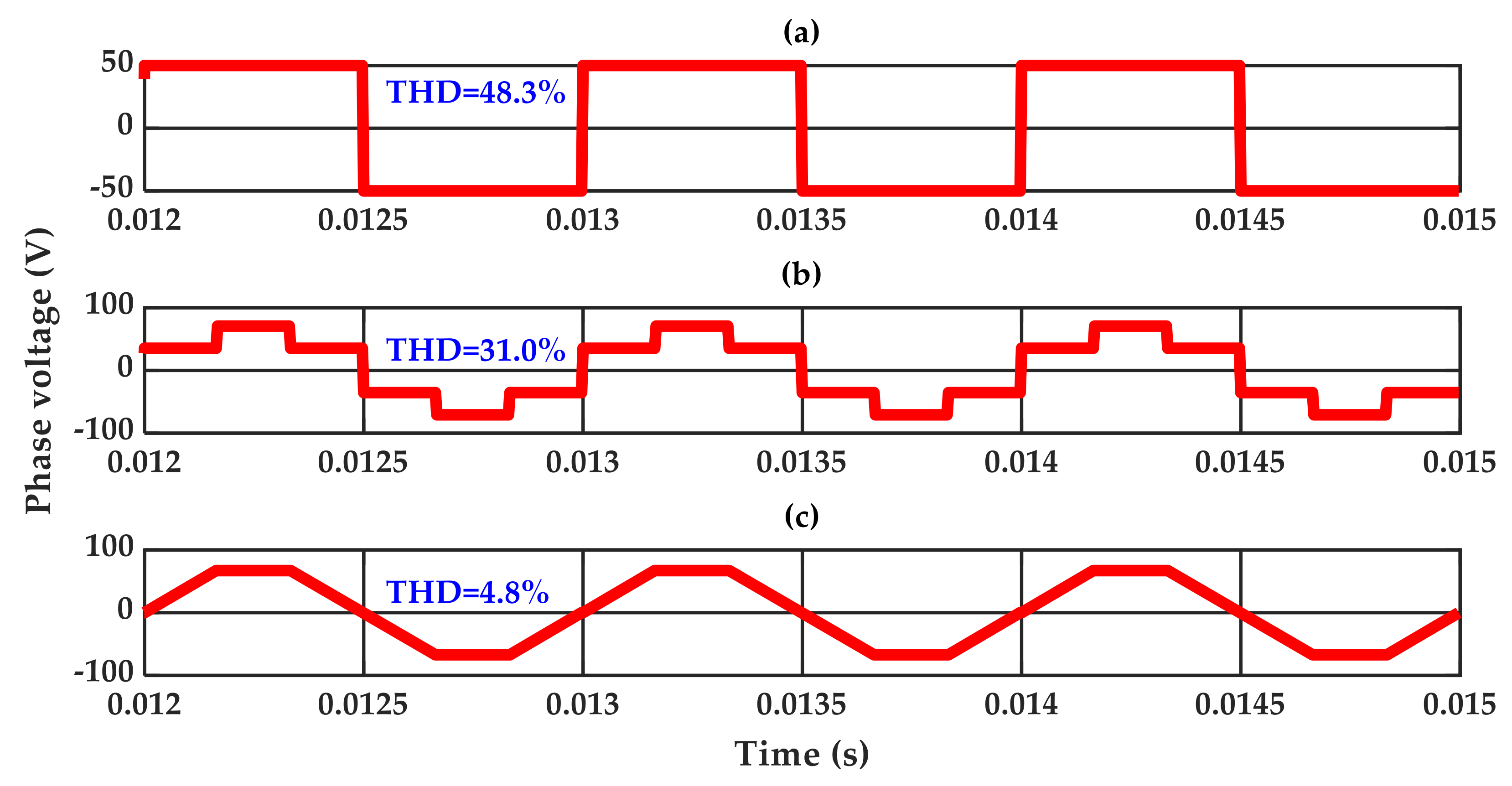
Perform the fast Fourier transform (FFT) analysis for the adopted nonsinusoidal symmetric supply waveforms. Extract the amplitudes E h n and phase angles ψ h n for N the most significant harmonics of the supply voltage of order { h 1 , h 2 , , h N }.
(II)
Discretise the model calculation area using standard first-order triangular elements. Re-number the mesh elements to separate the grids associated with the stator and rotor areas.
(III)
Set the null magnetic field strength in all ferromagnetic areas.
(IV)
Calculate the effective magnetic permeability distribution μ e f f for the stator and rotor core using the DC magnetization characteristics and the formula [31]:
μ e f f H h 1 , H h 2 , , H h N = B h 1 2 + B h 2 2 + + B h N 2 H h 1 2 + H h 2 2 + + H h N 2 ,
where: H h n —amplitude of the magnetic field strength related to h n supply voltage harmonic, B h n —magnetic flux density amplitude related to h n supply voltage harmonic:
B h n = 2 π 0 π μ D C H h 1 sin h 1 α + H h 2 sin h 2 α + + H h 1 sin h N α H h 1 sin h 1 α + H h 2 sin h 2 α + + H h N sin h N α sin h n α d α
(V)
Create and solve N of independent multi-harmonic linear field-circuit models, each including M of spatial harmonics of the magnetic field strength [30,31]:
M 11 μ e f f M 12 M 13 M 21 M 22 0 M 31 0 0 φ _ h n I _ S h n λ _ h n = 0 E _ S h n 0 ,
where: M 11 —matrix describing the magnetic and electrical properties of materials,   M 12   = M 21 T / j ω l z   —matrix describing the distribution and connection method of the stator winding, M 13 = M 31 T —matrices describing coupling between the rotor models and the stator model [23], M 22 —stator winding impedance matrix, φ _ h n —vector of the nodal values of the complex magnetic vector potential for the model associated with h n harmonic of the supplying voltage, I _ S h n —vector of the amplitudes of the loop currents in the stator winding due to h n harmonic of the supplying voltage, λ _ h n —vector of complex circulations of the magnetic field strength vector for the model associated with h n harmonic of the supplying voltage, E _ S h n —vector of the complex voltage amplitudes in the loops in the stator winding circuit associated with h n harmonic of the supplying voltage.
(VI)
Based on the calculated magnetic field distributions, φ _ h n calculate new values of the magnetic field strength H h n . Update the effective magnetic permeability distribution according to (3) and the matrix parameters M 11 in (5).
(VII)
Repeat steps IV–VI until convergence criterion based on relative change of the norm (equal to 0.1%) of the solution vector in (5) is reached.
The above procedure requires some additional comments. Firstly, it is assumed here that the nonlinearity of the stator winding currents must be considered as a superposition of nonlinear effects on the individual harmonic waveforms multiplied or divided by a time-invariant function (impedance related with magnetic permeability dependent only on magnitudes of magnetic quantities). The above means that the proposed method does not account for the saturation harmonics of magnetic flux and thus of current. In a solid rotor induction motor the saturation harmonics are, however, not significant due to the large value of inductance of the stator winding, and as shown in [30,31], the calculation results obtained in this way are very close to the ones coming from comprehensive time-domain computations.
It is still assumed that to determine the effective magnetic permeability, the higher harmonics of the magnetic field strength are to be used, and not the higher harmonics of flux density. Due to the fact that each model associated with a given voltage harmonic is a multi-harmonic model that includes M of spatial field harmonics, it is assumed that the magnetic field strength calculated in step (VI) is the RMS value of the magnetic field strength from M considered spatial harmonics, multiplied by 2 . In addition, each model related to the corresponding supply voltage harmonic must be formulated for the corresponding slip reference value related to the given voltage harmonic and the symmetrical voltage system it creates (positive, negative or zero). Theoretically, the proposed approach allows for taking into account any number of higher harmonics, because individual models are solved independently and their coupling is established only through their common value of the effective magnetic permeability, calculated after solving all particular models. Thus, the solution can be executed simultaneously on distributed or parallel systems. In [31], the effective magnetic permeability was determined as a multi-dimensional look-up table. This type of approach provides accurate results with a small (less than or equal to three) number of harmonics included. For a larger number of considered harmonics, in order to avoid large sizes of data files or interpolation errors, it is necessary to elaborate more suitable functions that calculate the value of effective magnetic permeability with the use of numerical integration procedures.

3. Calculation Results

The above approach was utilised to calculate the basic operating characteristics (phase current RMS and electromagnetic torque) of the machine described in Section 2.1 when supplied by three different waveforms presented in Figure 3 accompanied by their total harmonic distortion (THD) coefficients. The root mean square (RMS) value of the stator phase current I and the electromagnetic torque T e are determined on the basis of the following formula:
I = h 1 h N I h n 2 ,
T e = h 1 h N T e h n
where I h n and T e h n are, respectively, the RMS value and the electromagnetic torque, obtained as a result of solving the model related to the h n harmonic of the supply voltage.
The calculated characteristics were compared with the results obtained with the time-domain model and by adopting only one fundamental voltage harmonic with the RMS value equal to the RMS value of the original supply waveform (note that all the waveforms shown have the same 50 V RMS value). All the considered models were implemented by the authors in the Matlab scripting language (Mathworks, Natick, MA, USA) [38]. To discretise the computational area an open-source generator (GMSH) was used [39]. In each case, the five most significant harmonics of the supply waveforms and two main slot harmonics were used (−11, +13). Due to the star-connected winding without neutral wire, harmonics that are multiplicities of the third harmonic were not taken into account. As a result, in addition to the fundamental harmonics, harmonics 5, 7, 11 and 13 were also included. The voltage harmonics 1, 7 and 13 formed positive sequence of voltages, whereas the 5 and 11 formed a negative sequence of voltages. The obtained results of the calculations are shown in Figure 4.
When analysing the results of the calculations one can notice a very high consistency between the characteristics calculated using the proposed approach in relation to the results of the calculations using the standard model formulated in the time domain. At the same time, one can see that by providing equality of the real and modelled waveforms the use of the RMS value is sufficient when the supply waveform distortion is small (THD < 10%). The developed methodology is also characterized by a relatively short calculation time. When the models related to individual harmonics are solved sequentially using a standard PC (Intel Core i7-5820K CPU @ 3.30 GHz, 16 GB RAM), the solution time for the speed 24 krpm with the square waveform supply is 2.5 min. For the sake of comparison, the time-domain model solution time is 4 h 16 min.
In addition to determining the static characteristics of the analysed machine, the developed method also allows for the recovering of steady-state current waveforms and making an assessment, for example, of electromagnetic torque resulting from the interaction of individual harmonics, both related to the supply waveforms and the magnetic circuit grooves. The steady-state current waveform can be determined by solving individual component models related to the individual harmonics of the supply waveforms (see Figure 5) as
i t = h 1 h N 2 I _ h n cos h n ω + ψ h n
Since the electromagnetic torque is calculated as the sum of the components coming from individual slot harmonics (within the model related to the considered harmonic of the supply wave), it is possible to perform a detailed analysis of the influence of these harmonics on its value and sign. An example of such an analysis for synchronous speed with a square wave is presented in Table 2. Because the torque components correspond with different harmonic slips, these are not directly proportional to power dissipation in the rotor. The results of the rotor harmonic power dissipation computation are presented in Table 3. These clearly show that the disadvantageous effect of distorted voltage wave (first row in Table 3) is comparable to the disadvantageous effect of slotting (first column in Table 3). These results best demonstrate the machine design areas where the proposed modelling framework can be especially useful.
The above analysis was carried out at synchronous speed because only in such a case can the computed value of loss torque be compared with predictions obtained from a comprehensive time-domain model. It should be, however, noticed that the proposed model can be used at any speed allowing for a more detailed investigation on power dissipation in the rotor.

4. Including the Unbalance of Nonsinusoidal Voltage Waveforms

The developed approach can be generalized to cases where asymmetry is observed in voltage supply waveforms, including the nonsinusoidal ones. The idea of the presented method is based on an independent solution of coupled sub-models by the application of single effective magnetic permeability distribution. As shown above, despite the non-linearity of the problem, the use of the superposition principle allows one to obtain very accurate results. Therefore, in the case of supply unbalance, the method of symmetrical components can be used, allowing the presentation of the three-phase asymmetric distribution of a given harmonic of the supply waveform as a superposition of three symmetrical systems, namely the zero, positive and negative phase sequence system. To include the unbalance of the voltage supply, the model creation algorithm presented in the SubSection 2 should be modified as follows:
(I)
Perform FFT analysis for the adopted non-linear asymmetrical supply waveforms { e A t , e B t ,   e C t }. Extract the amplitudes E A h n ,   E B h n ,   E C h n and phase angles ψ A h n ,   ψ B h n ,   ψ C h n for N of the most significant harmonics of the supply voltage with orders { h 1 , h 2 , , h N }.
(II)
Determine the amplitudes of three-phase symmetrical systems of zero, positive and negative sequences, respectively E _ 0 h n ,   E _ 1 h n ,   E _ 2 h n for each most significant harmonics of the supply voltage E _ A h n ,   E _ B h n ,   E _ C h n :
E _ 0 h n E _ 1 h n E _ 2 h n = 1 3 1 1 1 1 a a 2 1 a 2 a E _ A h n E _ B h n E _ C h n
where a = e j 2 3 π .
(III)
Discretise the model calculation area using standard first-order triangular elements. Re-number the mesh elements to separate the grids associated with the stator and rotor areas.
(IV)
Set the null magnetic field strength in all ferromagnetic areas.
(V)
Calculate the effective magnetic permeability distribution according to (2).
(VI)
Create and solve 3N of the independent multi-harmonic linear field-circuit models related to zero, positive and negative sequences, assigned to individual harmonics of the supply voltage. Each one should take into account M spatial harmonics of the magnetic field strength. Calculate the requested operational parameters of the analysed machine according to (6)–(7), adopting I h n = I 0 h n 2 + I 1 h n 2 + I 2 h n 2 and T e h n = T 0 e h n + T 1 e h n + T 2 e h n . For a zero sequence of the supplying voltage, adopt pulsation close to zero.
(VII)
Based on the calculated magnetic field distributions, calculate new values of the magnetic field strength H h n = H 1 h n + H 2 h n , where H 1 h n and H 2 h n are the magnetic field strength derived from h n harmonic of the supply voltage as a result of solving the model associated with the positive and negative sequence. The influence of the zero-sequence system on the saturation of the magnetic circuit is disregarded. Update the effective magnetic permeability distribution according to (3) and the matrix parameters M 11 in (5).
(VIII)
Repeat steps V–VII until the convergence criterion based on the relative change of the maximum value of norm (equal to 0.1%) for all vectors of the solution of (5) is reached.
The above procedure was used to calculate the operational characteristics of the tested machine when supplied by the harmonic-rich square waveforms with the amplitude of one phase reduced by 25%. As shown in Figure 6 and Figure 7, the presented approach allows one to obtain predictions very close to ones obtained from a comprehensive time-domain model, even in the case of a lack of supply symmetry. The reason why the assumptions hold despite the asymmetry is that the circumferential distribution of winding magnetomotive force is always a periodic function as it depends on the circumferential distribution of the winding that has nothing to do with voltage asymmetry. Moreover, the degree of voltage asymmetry does not break the validity of the assumptions.
In the considered case, the solution time using the proposed model increases to 8 min, while the execution time of the complementary time-domain model solution time is similar to the previously presented case and equal to 4 h 30 min. Connected with a very good agreement of results, this result clearly exposes the benefits of the developed approach.
Looking from the practical point of view, it should be noticed that the voltage unbalance problem is effectively reduced in modern fault-tolerant power converters; however, the circumferential unbalance of magnetomotive force due to the faults of the motor winding is a much more common case of the faulty operation of induction motor drives. The corresponding computational problem can be effectively solved by the algorithm in Section 3 with both winding distribution-related and slot-related spatial harmonics taken into account.

5. Conclusions

The development of the strongly coupled multi-harmonic field model concept effectively accounted for the nonlinearity and asymmetry of the voltage supply in the calculation of the operating characteristics of a high-speed induction machine with a solid rotor in a steady-state complex-valued finite element modelling framework. According to the authors’ opinions, in combination with the previously developed numerical method of determining the rotor end-effect coefficient [21], the multi-harmonic field-circuit model may become an effective tool in the process of designing the above-mentioned motor type. In particular, this may be an effective tool in the investigations on the reduction of losses due to higher harmonics of the magnetic field of various origins.
Of course, the present work does not cover all aspects of the issue. Further research will be undertaken to consider losses in the stator package, hysteresis losses in the solid rotor and even the influence of the power supply using pulse-width modulation (PWM) converters.

Author Contributions

Conceptualization, T.G. and M.J.; methodology, T.G. and M.J.; software, T.G.; investigation, T.G.; resources, T.G.; data curation, T.G.; writing—original draft preparation, T.G.; writing—review and editing, M.J.; visualization, T.G.; supervision, M.J.; project administration, T.G. All authors have read and agreed to the published version of the manuscript.

Funding

This research received no external funding.

Conflicts of Interest

The authors declare no conflict of interest.

References

  1. O’Kelly, D. Theory and performance of solid rotor induction and hysteresis machines. Proc. Inst. Electr. Eng. 1976, 123, 421–428. [Google Scholar] [CrossRef]
  2. Wood, A.J. An analysis of solid rotor machines Part I. Operational impedances and equivalent circuits. Trans. Am. Inst. Electr. Eng. 1959, 78, 1657–1665. [Google Scholar] [CrossRef]
  3. Sarma, M. Current density distribution in solid-rotor induction motor. IEEE Trans. Magn. 1979, 15, 1473–1475. [Google Scholar] [CrossRef]
  4. Brunelli, B.; Casadei, D.; Reggian, U.; Serra, G. Transient and steady-state behaviour of solid rotor induction machines. IEEE Trans. Magn. 1983, 19, 2650–2654. [Google Scholar] [CrossRef]
  5. Zaim, M.E. Non-linear models for the design of solid rotor induction machines. IEEE Trans. Magn. 1999, 35, 1310–1313. [Google Scholar] [CrossRef]
  6. Kurvinen, E.; Chong, D.; Petrov, I.; Nerg, J.; Liukkonen, O. Design And Manufacturing of A Modular Low-Voltage Multi-Megawatt High-Speed Solid-Rotor Induction Motor. IEEE Trans. Ind. Appl. 2021. [Google Scholar] [CrossRef]
  7. Dongdong, Z.; Ruichi, A.; Chengyuan, H.; Lixiao, B.; Wu, T. Electromagnetic Design of A Megawatt High Efficiency High Speed Solid Rotor Induction Motor. In Proceedings of the IEEE International Electric Machines and Drives Conference (IEMDC), Miami, FL, USA, 21–24 May 2017. [Google Scholar] [CrossRef]
  8. Haisen, Z.; Chengyang, C.; Eldeeb, H.; Yang, Z.; Guorui, X.; Mohammed, O. Optimal Design Of High-Speed Solid-Rotor Cage Induction Motors Considering Ferromagnetic Materials Behavior And Manufacturing Process. IEEE Trans. Ind. Appl. 2020, 56, 4345–4355. [Google Scholar] [CrossRef]
  9. Gulbahce, M.; Kocabas, D. High-speed solid rotor induction motor design with improved efficiency and decreased harmonic effect. IET Electr. Power Appl. 2018, 12, 1126–1133. [Google Scholar] [CrossRef]
  10. Chong, D. Modeling and Analysis of a High-Speed Solid-Rotor Induction Machine. Ph.D. Thesis, Lappeenranta–Lahti University of Technolog, Espoo, Finland, 2020. [Google Scholar]
  11. Pyrhönen, J.; Nerg, J.; Kurronen, P.; Lauber, U. High-speed high-output solid-rotor induction-motor technology for gas compression. IEEE Trans. Ind. Electron. 2010, 57, 272–280. [Google Scholar] [CrossRef]
  12. Shaofeng, C.; Yaofei, H.; Zhixun, M.; Guozhen, C.; Shuai, X.; Jikai, S. Influence Analysis of Structural Parameters on the Performance of 120° Phase Belts Toroidal Winding Solid Rotor Induction Motor. Energeies 2020, 13, 5387. [Google Scholar] [CrossRef]
  13. Feng, H.; Si, J.; Wu, W.; Dong, L.; Cheng, Z. Equivalent Circuit Parameter Calculations and Characteristics Analysis of 2-DoF Direct Drive Induction Motor with a Slotted Solid Rotor. Appl. Sci. 2019, 9, 2191. [Google Scholar] [CrossRef] [Green Version]
  14. Gieras, J.; Saari, J. Performance Calculation for a High-Speed Solid-Rotor Induction Motor. IEEE Trans. Ind. Electron. 2011, 59, 2689–2700. [Google Scholar] [CrossRef]
  15. Siyuan, G.; Libing, Z.; Tong, Y. An analytical method for determining circuit parameter of a solid rotor induction motor. In Proceedings of the 15th International Conference on Electrical Machines and Systems (ICEMS), Sapporo, Japan, 21–24 October 2012. [Google Scholar]
  16. Markovic, M.; Perriard, Y. An analytical solution for the torque and power of a solid-rotor induction motor. In Proceedings of the IEEE International Electric Machines & Drives Conference, Niagara Fails, ON, Canada, 15–18 May 2011. [Google Scholar] [CrossRef]
  17. Räisänen, V.; Suuriniemi, S.; Kurz, S.; Kettunen, L. Rapid Computation of Harmonic Eddy-Current Losses in High-Speed Solid-Rotor Induction Machines. IEEE Trans. Energy Conv. 2013, 28, 782–790. [Google Scholar] [CrossRef]
  18. Wu, W.; Si, J.; Feng, H.; Cheng, Z.; Hu, Y.; Gan, C. Rotor Eddy Current Loss Calculation of a 2DoF Direct-Drive Induction Motor. Energies 2019, 12, 1134. [Google Scholar] [CrossRef] [Green Version]
  19. Di, C.; Petrov, I.; Pyrhönen, J.; Chen, J. Accelerating the Time-Stepping Finite-Element Analysis of Induction Machines in Transient-Magnetic Solutions. IEEE Access 2019, 7, 122251–122260. [Google Scholar] [CrossRef]
  20. Di, C.; Petrov, I.; Pyrhönen, J. Extraction of Rotor Eddy-Current Harmonic Losses in High-Speed Solid-Rotor Induction Machines by an Improved Virtual Permanent Magnet Harmonic Machine Model. IEEE Access 2019, 7, 27746–27755. [Google Scholar] [CrossRef]
  21. Garbiec, T. Fast Computation of Performance Characteristics for Solid-Rotor Induction Motors With Electrically Inhomogeneous Rotors. IEEE Trans. Energy Conv. 2016, 31, 1688–1696. [Google Scholar] [CrossRef]
  22. Lin, J.D.; Zhou, P.; Chen, N.; Lu, C.; Christini, M. Fast Methods for Reaching AC Steady State in FE Transient Analysis. In Proceedings of the IEEE International Electric Machines and Drives Conference (IEMDC), Miami, FL, USA, 21–24 May 2017. [Google Scholar] [CrossRef]
  23. Dyck, D.N.; Weicker, P.J. Periodic Steady-State Solution of Voltage-Driven Magnetic Devices. IEEE Trans. Magn. 2007, 43, 1533–1536. [Google Scholar] [CrossRef]
  24. Rosu, M.; Zhou, P.; Lin, D.; Ionel, D.M.; Popescu, M.; Blaabjerg, F.; Rallabandi, V.; Staton, D. Multiphysics Simulation by Design for Electrical Machines, Power Electronics and Drives; John Wiley & Sons: Hoboken, NJ, USA, 2017. [Google Scholar]
  25. De Gersem, H.; Hamayer, K. Air-Gap Flux Splitting for the Time-Harmonic Finite-Element Simulation of Single-Phase Induction Machines. IEEE Trans. Magn. 2002, 38, 1221–1224. [Google Scholar] [CrossRef]
  26. De Gersem, H.; De Brabandere, K.; Belmans, R.; Hameyer, K. Motional time-harmonic simulation of slotted single-phase induction machines. IEEE Trans. Energy Convers. 2002, 17, 313–318. [Google Scholar] [CrossRef]
  27. Räisänen, V.; Suuriniemi, S.; Kettunen, L. Generalized Slip Transformations and Air-Gap Harmonics in Field Models of Electrical Machines. IEEE Trans. Magn. 2016, 52, 1–8. [Google Scholar] [CrossRef]
  28. Mezani, S.; Laporte, B.; Takorabet, N. Saturation and space harmonics in the complex finite element computation of induction motors. IEEE Trans. Magn. 2005, 41, 1460–1463. [Google Scholar] [CrossRef]
  29. Ouazir, Y.; Takorabet, N.; Ibtiouen, R.; Touhami, O.; Mezani, S. Consideration of space harmonics in complex finite element analysis of induction motors with an air-gap interface coupling. IEEE Trans. Magn. 2006, 42, 1279–1282. [Google Scholar] [CrossRef]
  30. Garbiec, T.; Jagiela, M.; Kulik, M. Application of Nonlinear Complex Polyharmonic Finite-Element Models of High-Speed Solid-Rotor Induction Motors. IEEE Trans. Magn. 2020, 56. article no. 7515304. [Google Scholar] [CrossRef]
  31. Garbiec, T.; Jagiela, M. Accounting for Magnetic Saturation Effects in Complex Multi-harmonic Model of Induction Machine. Energies 2020, 13, 4670. [Google Scholar] [CrossRef]
  32. Davat, B.; Ren, Z.; Lajoie-Mazenc, M. The movement in field modeling. IEEE Trans. Magn. 1985, 21, 2296–2298. [Google Scholar] [CrossRef]
  33. Escarela-Perez, R.; Campero-Littlewood, E. Moving-band and sliding-surface combined technique for the simulation of rotor motion in transient FEM modelling of electrical machines. In Proceedings of the International Conference on Electrical Machines (ICEM), Espoo, Finland, 28–30 August 2000. [Google Scholar]
  34. Singh, G.K. A research survey of induction motor operation with non-sinusoidal supply wave forms. Electr. Power Sys. Res 2005, 75, 200–213. [Google Scholar] [CrossRef]
  35. Doggett, L.A.; Queer, E.R. Induction motor operation with non-sinusoidal impressed voltages. AIEE Trans. 1929, 48, 1217–1223. [Google Scholar]
  36. Chalmer, B.J.; Sarkar, B.R. Induction motor losses due to non-sinusoidal supply waveforms. Proc. Inst. Electr. Eng. 1968, 115, 1777–1782. [Google Scholar] [CrossRef]
  37. Klingshirn, E.A.; Jordan, H.E. Poly phase induction motor performance and losses on nonsinusoidal voltage sources. IEEE Trans. Power Appar. Syst. 1968, PAS-87, 624–631. [Google Scholar] [CrossRef]
  38. Available online: https://www.mathworks.com/products/matlab.html (accessed on 28 June 2021).
  39. Available online: https://gmsh.info (accessed on 28 June 2021).
Figure 1. Solid rotor induction machine taking into consideration: (a) dimensions of the stator package (cross-section area), (b) dimensions of the rotor [31].
Energies 14 05404 g001
Figure 2. DC magnetization curves used in computations.
Energies 14 05404 g002
Figure 3. Three different types of supply waveforms considered in computations: square (a), six-step (b) and trapezoidal (c).
Energies 14 05404 g003
Figure 4. Results of computations: electromagnetic torque (a) and RMS stator current (b) for square supply waveforms (see Figure 3a); electromagnetic torque (c) and RMS stator current (d) for six-step supply waveforms (see Figure 3b); electromagnetic torque (e) and RMS stator current (f) for trapezoidal supply waveforms (see Figure 3c). Results obtained using the single-harmonic model and the proposed model are practically the same.
Energies 14 05404 g004aEnergies 14 05404 g004b
Figure 5. Comparison of the phase current waveforms calculated with the use of the time-domain model (red line) with the waveforms calculated with the use of the developed method (blue line) for a rotational speed of 24,000 rpm: square supply waveform (a), six-step supply waveform (b), trapezoidal supply waveform (c).
Energies 14 05404 g005
Figure 6. Results of computations for the square nonsymmetrical supplying waveforms: electromagnetic torque (a) RMS stator currents (b).
Energies 14 05404 g006aEnergies 14 05404 g006b
Figure 7. Comparison of the phase currents waveforms calculated with the use of the model formulated in the time domain (red line) with the waveforms calculated with the use of the developed method (blue line), as a superposition of harmonic waveforms, for the rotational speed of 24,000 rpm when supplied with square waveforms and 25% amplitude asymmetry.
Energies 14 05404 g007
Table 1. Basic specifications of tested induction motor [31].
ParameterValue
Nominal power125 W
Operation frequency (ω)2000π rad/s
Number of pole pairs (p)2
RMS phase voltage50 V
Phase resistance0.62 Ω
End-winding leakage inductance98 μH
Rotor conductivity5.2 MS/m
Machine length (lz)32 mm
Number of stator slots24
Table 2. The results of the electromagnetic torque computations for the synchronous speed (30,000 rpm) in mNm produced by the interaction of the harmonics of the magnetic field in the gap ( n —time harmonic number of voltage supply, m —spatial harmonic ordinal number). Value of total electromagnetic torque obtained from the time-domain analysis is −4.256 mNm.
n+1−5+7−11+13
m
+10(S)−0.249(B)0.065(M)−0.013(B)0.007(M)Σ = −0.190
−11−2.714(B)−0.008(G)−0.004(B)0(S)−0.005(B)Σ = −2.731
+13−0.560(G)−0.002(B)−0.003(G)−0.002(B)0(S)Σ = −0.567
Σ = −3.274Σ = −0.259Σ = 0.058Σ = −0.015Σ = 0.002Σ = −3.488
(S): rotor in sync, (B): braking mode operation, (G): generating mode operation, (M): motoring mode operation, (+) means positive phase sequence, (−) negative phase sequence relative to the stator.
Table 3. The results of the rotor power dissipation computations for the synchronous speed (30,000 rpm) in Watt ( n —time harmonic number of voltage supply, m —spatial harmonic ordinal number). Value of total rotor power dissipation obtained from the time-domain analysis is 19.97 W.
n+1−5+7−11+13
m
+10(S)4.467(B)1.171(M)0.455(B)0.234(M)Σ = 6.327
−118.520(B)0.013(G)0.017(B)0(S)0.003(B)Σ = 8.553
+131.488(G)0.008(B)0.001(G)0.001(B)0(S)Σ = 1.498
Σ = 10.008Σ = 4.488Σ = 1.189Σ = 0.456Σ = 0.237Σ = 16.378
(S): rotor in sync, (B): braking mode operation, (G): generating mode operation, green: motoring mode operation, (+) means positive phase sequence, (−) negative phase sequence relative to the stator.
Publisher’s Note: MDPI stays neutral with regard to jurisdictional claims in published maps and institutional affiliations.

