Abstract
Molten salts eutectics are promising candidates as phase change materials (PCMs) for thermal storage applications, especially considering the possibility to store and release heat at high temperatures. Although many compounds have been proposed for this purpose in the scientific literature, very few data are available regarding actual applications. In particular, there is a lack of information concerning thermal storage at temperatures around 600 °C, necessary for the coupling with a highly efficient Rankine cycle powered by concentrated solar power (CSP) plants. In this contest, the present work deals with a thermophysical behavior investigation of a storage heat exchanger containing a cost-effective and safe ternary eutectic, consisting of sodium chloride, potassium chloride, and sodium carbonate. This material was preliminarily and properly selected and characterized to comply with the necessary melting temperature and latent enthalpy. Then, an indirect heat exchanger was considered for the simulation, assuming aluminum capsules to confine the PCM, thus obtaining the maximum possible heat exchange surface and air at 5 bar as heat transfer fluid (HTF). The modelling was carried out setting the inlet and outlet air temperatures at, respectively, 290 °C and 550 °C, obtaining a realistic storage efficiency of around 0.6. Finally, a conservative investment cost was estimated for the storage system, demonstrating a real possible economic benefit in using these types of materials and heat exchange geometries, with the results varying, according to possible manufacturing prices, in a range from 25 to 40 EUR/kWh.
1. Introduction
The world energy demand, which could rise by 1.3% each year to 2040, is an imminent challenge to be faced [1,2,3]. Recent climate agreements and international policies encourage the reduction of fossil fuels-based energy consumption, mainly through the increase of renewable energy sources (RES), such as wind or solar. However, these technologies suffer from intermittent and unstable energy output, which can be overcome by coupling with heat storage systems.
Thermal energy storage (TES) materials, based on sensible (SH) and latent heat (LH, phase change materials (PCM)) are considered viable solutions for this purpose. In particular, the formers represents the most established technology at an industrial scale, as they have been largely exploited in concentrated solar plants (CSP), where solar energy is converted into thermal power [4,5,6]. These systems are expected to reach a worldwide capacity of 982GW by 2050, supplying 11% of the global electricity [7,8]. More recently, latent heat storage technologies are gaining growing interest thanks to the possibility to obtain higher energy densities compared to sensible heat storage systems [9]. LH accumulation takes advantage of energy absorbed or released during phase changing, typically liquefaction or solidification. This enables the storage of a large amount of heat at the phase transition point, making it suitable for those several processes that require thermal energy at constant temperature (e.g., electricity generation in Rankine cycles thermal power plants). A proper PCM should ideally satisfy the following requirements:
- Suitable phase change temperature;
- Large phase change enthalpy (at least 50 kJ/kg);
- Complete reversibility and good cycling stability avoiding phases separation;
- Little sub-cooling to assure that melting and solidification can proceed to a narrow temperature range;
- Good thermal conductivity;
- Low vapour pressure;
- Small volume change;
- Chemical stability;
- Compatibility with the vessel and the surrounding materials;
- Safe, non-toxic and non-flammable species;
- High availability of materials at acceptable cost;
- Positive life cycle assessment (LCA).
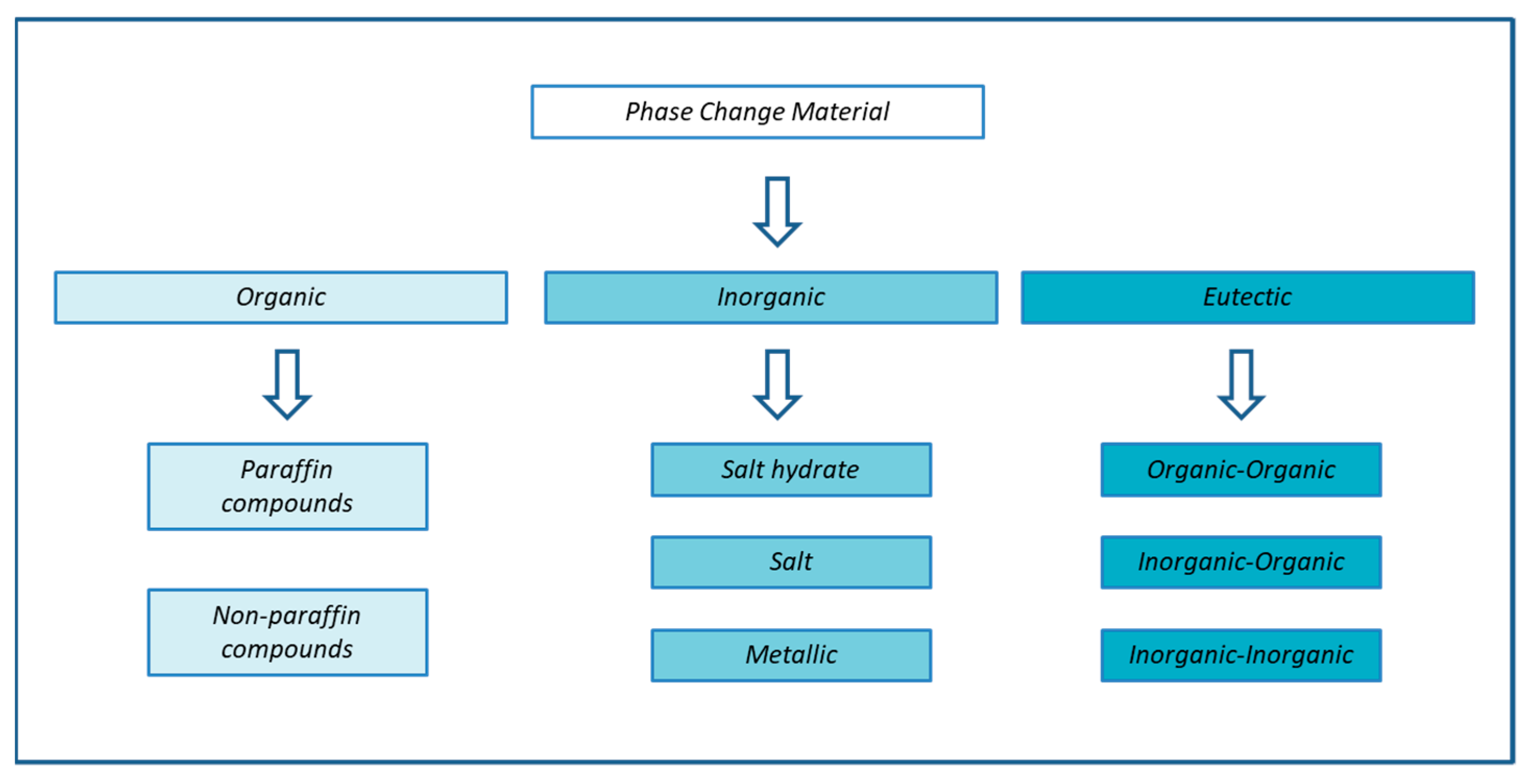
The main investigated systems comply with most of the above criteria and include organic compounds, metals, salts, and their eutectics [10,11,12], as summarized in Figure 1. Actually, organics are oxidizable materials and have to be used below their thermal stability limit or segregated from the air, and molten salts can be extremely corrosive (especially chlorides and carbonates) and can require to be confined using expensive alloys [13,14].
Figure 1.
General classification of PCM.
PCMs are available in a broad temperature range. Hoshi et al. [15] classified these materials according to their melting points, establishing three temperatures ranges: low below 220 °C, medium between 220 and 420 °C, and high above 420 °C. Regarding the latter, numerous molten salts mixtures can be feasibly employed, as shown in Table 1. For single compounds, the melting point tends to increase following the sequence of nitrates, chlorides, carbonates, and fluorides. Another way to categorize PCMs is by examining their latent heat and consequent storage density capacity, as reported in Table 2 [16].
Table 1.
Thermophysical properties for pure or mixed molten salts for high-temperature applications [16]. ** % mol/mol.
Table 2.
Inorganic PCMs with melting temperature above 400 °C, latent heat and energy density.
Organic compounds consist of paraffin waxes, esters, acids, and alcohols; inorganic materials include salt hydrates, eutectics of inorganic salts, metals, and their eutectics. Organic materials species generally cover the temperature range up to 200 °C, but due to the presence of covalent bonds, most of them are not stable to high temperatures, showing additionally a relatively low density and, as a consequence, smaller melting enthalpies per volume than inorganic materials.
Metals PCMs usually have similar melting enthalpies per mass with respect to salt but higher energy volumetric accumulation due to their higher density. Their main disadvantage is the coupling compatibility with construction materials and heat transfer fluids [17]. Overall, molten salts and their mixtures look like the most suitable compounds for heat storage at high temperatures.
Although several PCM TES systems have been proposed in the scientific literature (Table 2), very few results have been presented about applications in the 420–600 °C range, necessary to increase the efficiency of Rankine cycle power blocks [18,19,20,21,22].
Moreover, little is available regarding the configuration of a suitable heat exchanger. In general, as far as latent heat storage is concerned, direct and indirect systems can be considered [23]. Direct systems facilitate heat transfer through immediate contact between the heat transfer fluid (HTF) and the PCM. Indirect systems separate the HTF and storage material with a solid heat transfer border: thermal energy can both be delivered from and to a container filled with the PCM, and heat transfer occurs by way of pipes, finned tubes, or flat-plate exchangers, or the material is confined in capsules. The latter technique is of particular interest because it allows maximizing the PCM surface in contact with the HTF [10,24]. This aspect overcomes, at least partially, the problems related to volume changes during phase transitions. The shape of the encapsulation depends on the applications, and the material must be compatible with the contained PCM [25]
Packed bed reactor configurations are among the most suitable systems in the storage field [26], and the related thermal efficiency studies are mainly performed through numerical simulation approaches, pioneered by Schumann [27], who proposed one of the most adopted modelling methods. Ismail [28] reported successively on a packed bed cylindrical reactor composed of spherical capsules (made of different materials, such as copper, aluminum and polyethylene) filled with water as PCM: a numerical model and experimental investigation were performed to assess the charging/discharging efficiency for cold storage. While most articles have been focused on low-temperature PCM applications [28], whereas fewer works are related to higher thermal levels. Peng et al. [29] investigated a storage system involving sodium nitrite as PCM in a temperature range from 200 to 400 °C, with solar salt utilized as HTF. Bellan et al. [30] proposed sodium nitrate as encapsulated PCM (working at about 300 °C), using air as HTF and analyzing experimentally and theoretically the dynamic thermal performances as a function of the heat exchanger operating parameters.
To summarize, no data are currently available about PCM packed-bed heat exchangers operating at high-temperature levels, especially around 600 °C, although this value is of particular interest given a Rankine power block presents a quite high efficiency if the steam operates between 530 and 240 °C [22,31]. In particular, a storage system presenting this working temperature can be suitable for CSP configurations operating with air as HTF. In this contest, both towers with central receivers [32] and, less often, parabolic trough plants [33] have been experimentally and theoretically investigated. Regarding the formers, excluding some exception [34], this type of arrangements are currently coupled, or proposed to be coupled, with a Brayton cycle as a power generator [35], but several recent studies showed significant benefits in using hybrid CSPs with a combined cycle (CC), where Brayton and Rankine sections are configured in series in order to increase the efficiency [36,37,38]. In this regard, the system investigated in this work can be proposed as heat accumulator for the Rankine power block, along with another storage equipment necessary for the higher temperatures required by the Brayton cycle.
In particular, an eutectic chloride-carbonate based salt (NaCl-KCl-Na2CO3) was selected for operating near 600 °C and, at the same time, to provide low environmental impact and toxicity [24], along with low cost and high availability of the single basic components.
For this purpose, the mixture thermal properties were experimentally determined, including melting temperature, specific heat, latent heat and storage energy density, while thermal conductivity was estimated. In order to maximize the heat exchange surface, a spherical encapsulation is considered in this work, with aluminum selected as separation material, given both its feasible thermal conductivity properties and good compatibility with the molten salts [39]. Clearly, this configuration type is expectably more costly than arrangements where the PCM is inserted in shells, tubes, or macrocapsules. On the other hand, a fixed bed presenting small particles can lead to a quite high, efficient heat exchange, and the techniques for microencapsulation could become more cost-effective in the future. Although chlorides are reported to be highly corrosive for stainless steel [13], this latter material was proposed for the tank, assuming a predictable limited extent for eventual PCM leakages.
Then, the selected packed-bed was simulated by a fluid dynamic model, in order to calculate the efficiency of the storage system. Finally, a realistic investment cost analysis was carried, and the results were compared with commonly used commercial storage systems.
2. Materials and Methods
2.1. Sample Preparation
A ternary mixture of sodium chloride (NaCl), potassium chloride (KCl), and Ssodium carbonate Na2CO3) (0.26/0.40/0.34 mol fraction) was selected as the PCM material characterized in this work [40]. Analytical grade salts were purchased by Sigma-Aldrich: NaCl (CAS number 7647-14-5), KCl (CAS number 7447-40-7) and Na2CO3 (CAS number 497-18-8). The pure compounds were mixed according to the eutectic weight percentages in order to synthetize about 10 gr of final product, dissolved in about 40 mL of deionized water, and then, the aqueous mixture was agitated for about 30 min to obtain a complete solubilization. The solutions were then dehydrated under stirring by employing a heated plate and maintaining the water temperature at the boiling point; the whole evaporation process took around 3 h to be completed. The acquired ternary salt was finally poured into a mortar and made as fine and homogeneous as possible.
2.2. Experimental Measurements
The PCM thermo-physical properties were experimentally investigated, including latent heat, heat capacity, density, and thermal conductivity of the PCM material.
To evaluate both latent heat and heat capacity, a DSC 1 Mettler Toledo was employed. The measurements were performed under an inert ambient provided by a nitrogen flow of 40 Nml/min.
The latent heat was measured by a DTA analysis between 50 °C and 600 °C, using heating and cooling ramps at 10 °C/min. Its value, with a relative error of ±10%, was obtained by integrating the endothermic and exothermic phase transition peaks. With this technique, the reference and sample crucible are placed inside the same heating cell. When an endothermic process occurs, sample temperature rises slower than the reference temperature, because of the heat absorbed during the melting process. On the contrary, during an exothermic process (e.g., solidification), the sample temperature resulted higher than the reference one. The difference between the temperatures is proportional, by a calibration curve, to the absorbed heat flow, visualized as the resulting DSC peak, and the peak onset represents the start of the sample phase change.
The standard DSC method for calculating the heat capacity is provided by the protocol DIN51007, where the heat capacity is determined by comparison with pure sapphire (NIST), employing a series of isothermal steps alternated with temperature heating ramps (10 °C/min). The assessed experimental uncertainty was around ±5%.
Density measurement in the liquid phase was performed taking advantage of Archimedes’ principle: for this purpose, a dynamometer was used to measure the difference between gravity and Archimedes buoyancy forces. Solid-phase apparent density was determined at room temperature by a pycnometer after re-solidification of the PCM.
Thermal conductivity was estimated by literature references regarding the constituent pure compounds values.
2.3. Modelling Numerical Method and Governing Equations
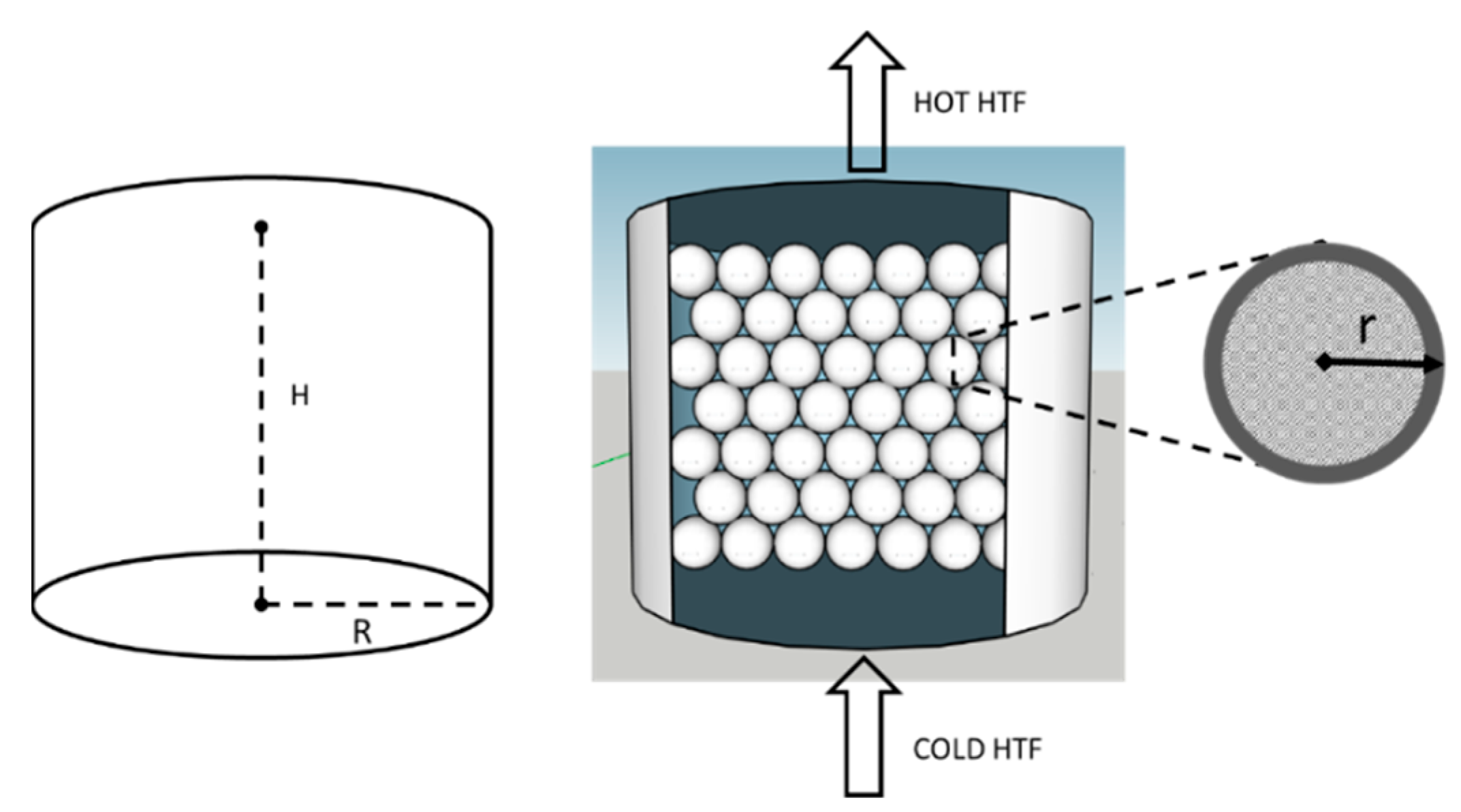
In order to assess the performances of the PCM for energy storage purposes, a direct contact configuration was assumed. The heat exchanger was modelled considering a cylindrical geometry where the HTF (pressurized air) flows vertically, as schematized in Figure 2. The capsule diameter was assumed to be 5 cm, as a good compromise between a proper heat exchange and a feasible preparation of the material; as a consequence, each capsule includes about 127 g of PCM.
Figure 2.
The heat exchanger unit geometry scheme used for the modelling.
A MATLAB 2020 pdepe function was used to solve the differential equations system. The equations necessary to define the heat exchanger mass and energy balances are reported in Table 3. To take into account the convective energy exchange with spherical particles, it is necessary to define a parameter “aPCM” (1) that is equal to the PCM surface per length divided by the tank section [41,42,43] (2). The thermal resistances of, respectively, air, PCM, and aluminum shell are defined in (5)–(7). The Reynolds number for packed beds [43] was calculated with (9) [11], using the HTF mass flow rate from (3), while the convective heat transfer coefficient between PCM and air (4) was evaluated utilizing the method described by Xu et al. [8], with the Prandtl parameter defined in (10).
Table 3.
Equations necessary to determine: Reynolds, Prandtl numbers, and the heat exchange global coefficient (P = 5 bar, = 420 °C).
The heat exchange behavior as a function of time and HX length is described by the 1-D scalar energy expressions for HTF and PCM (11) and (12), as listed in Table 4 The z coordinate is evidently the flow direction of the HTF.
Table 4.
1-D Energy governing equations, which describe the heat exchange between PCM and air, as a function of time and HX length.
The following assumptions were considered:
- Tank walls are adiabatic and heat losses are neglected;
- PCM and HTF temperatures change only along the direction in which the HTF flows;
- Averaged thermo-physical properties of PCM and HTF are assumed as constant and independent of the temperature variation.
The PCM enthalpy is defined in (13) and (14) as the sum between the PCM latent and sensible heats, calculated imposing a PCM final discharging temperature of 573K (300 °C), that is the minimum realistic value to allow heat exchange with the HTF. In turn, the PCM temperature is related to its enthalpy level (15).
To solve the partial differential equations, the initial and boundary conditions were set according to the input parameters used for mass and energy balances, as shown in Table 5.
Table 5.
Boundary conditions related to (11) and (12).
3. Results
3.1. Experimental Results
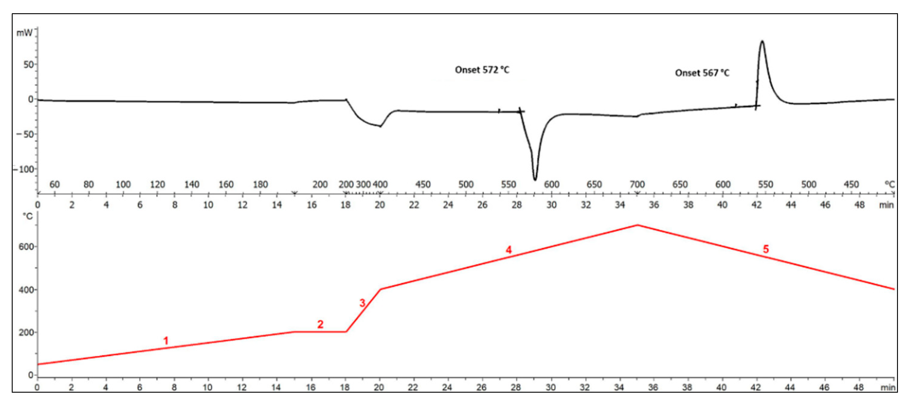
The eutectic composition of the ternary mixture was verified by DTA, showing, within the experimental error, the equivalence of the solidus (initial melting) and liquidus (initial solidification) temperatures, as reported in Figure 3. The latter was about 5 degrees lesser due to a small overcooling effect. Overall, the phase change temperature resulted of 572 °C.
Figure 3.
TGA/DSC analysis to determine liquidus and solidus temperatures of the ternary eutectic used as PCM. The figure shows, on the top, the heat flow with the onset temperatures marked and, on the bottom, the temperature program applied. The test was carried out under a flow of 40 Nml/min of N2.
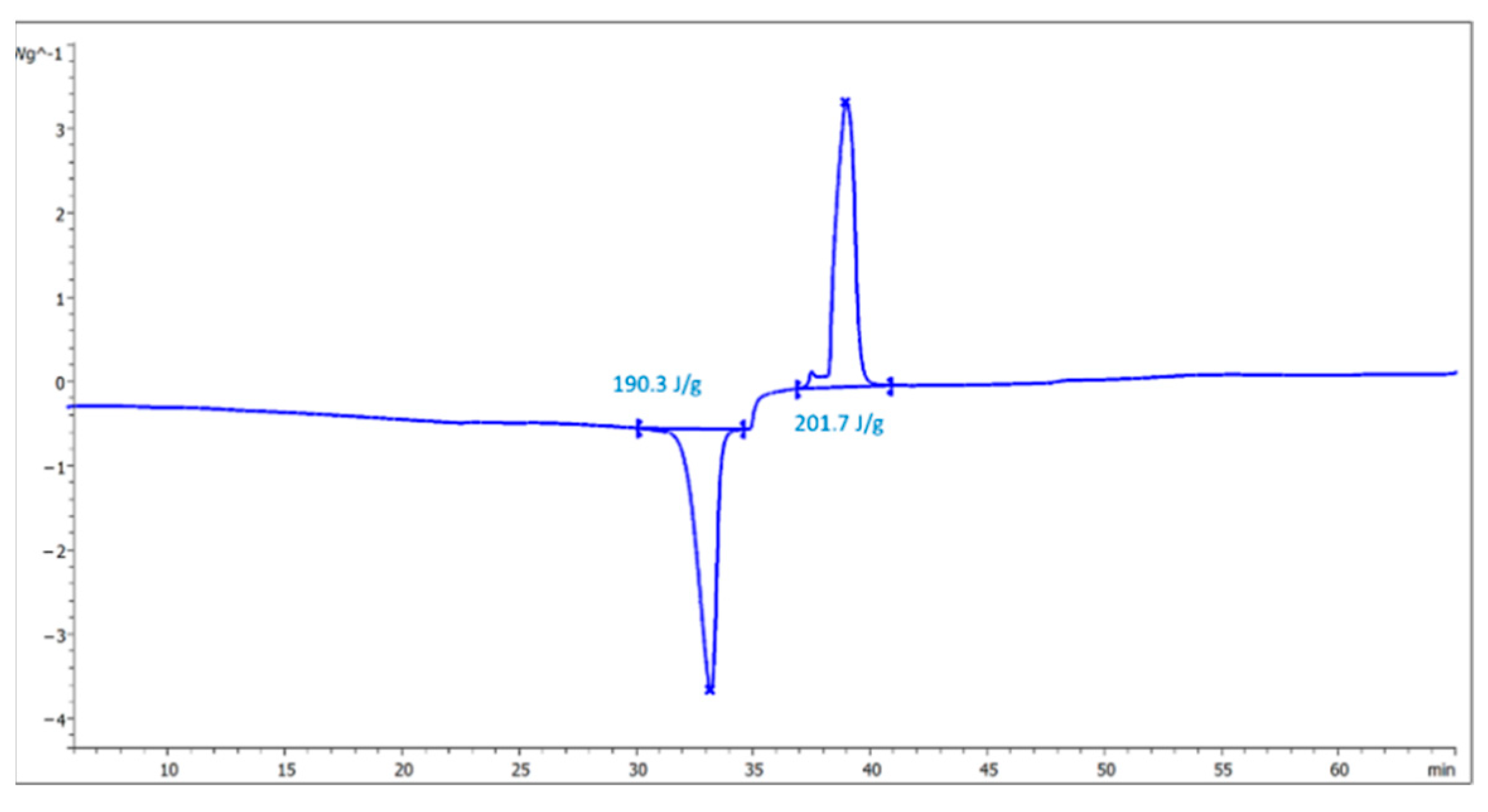
Always by DTA, it was possible to determine the latent heat (Figure 4), averaging the liquefaction and solidification enthalpies, that present very close values, demonstrating the absence of significant kinetics phenomena and the cyclability of the process.
Figure 4.
DSC Latent heat evaluation of the ternary PCM eutectic.
The value of density in the liquid state was measured just above the phase change point, and it was found to be approximately 2.05 g/cm3. In the solid phase, the density value of the powder, obtained after having melted and solidified again the PCM, was around 1.94 g/cm3. This value represents an “apparent” behavior; in fact, the stable phase of solid salts presents, as a rule, a higher density than the one in the molten form [44].
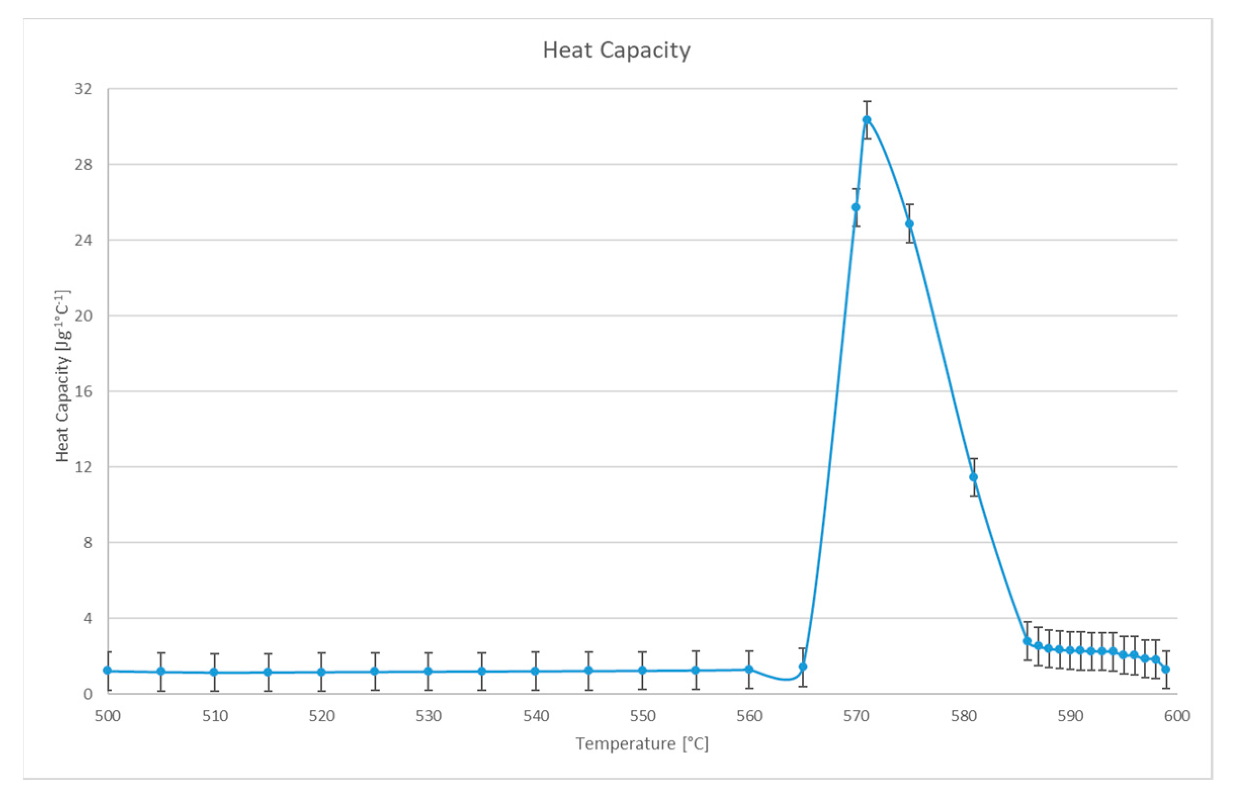
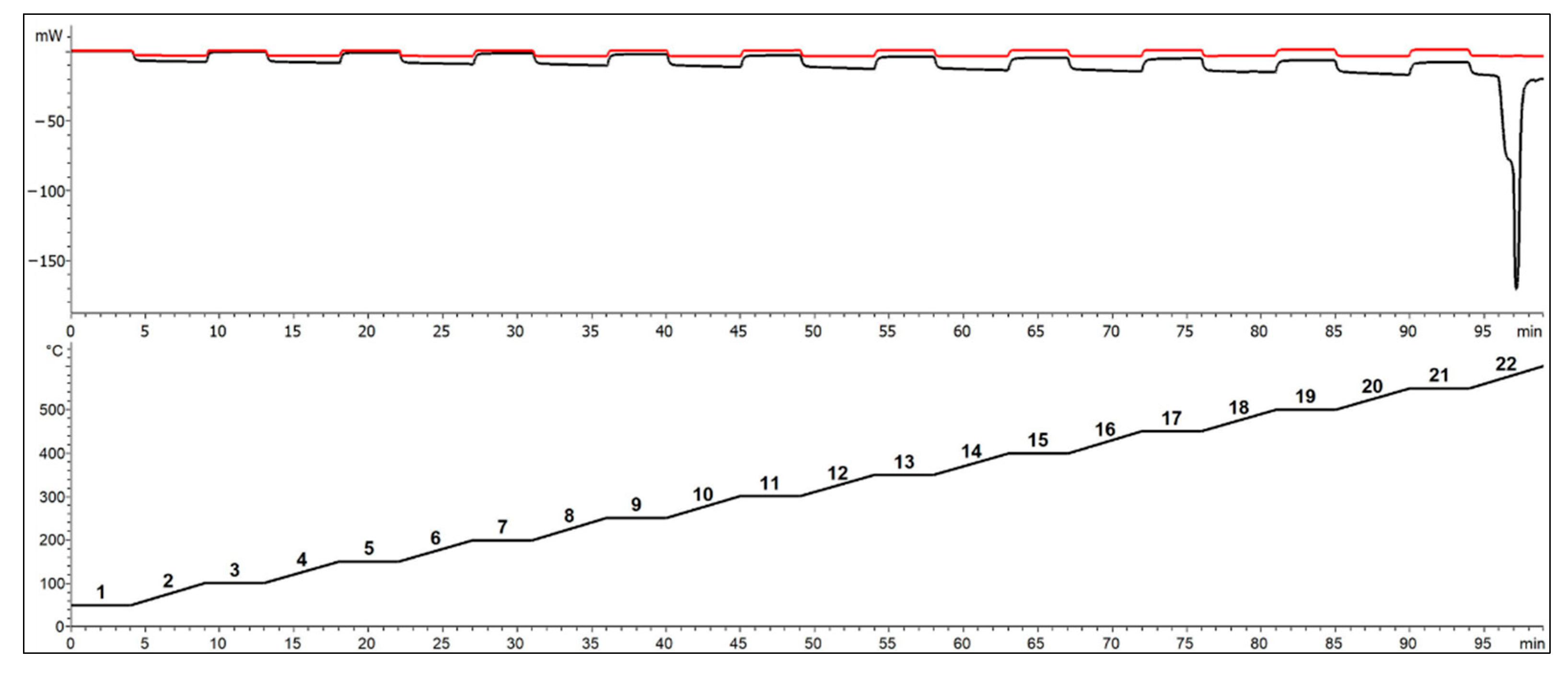
For specific heat determination, six independent measurements of the eutectic mixture were carried out. An example is shown in Figure 5, where are reported, respectively, the curves for sapphire, sample, and the specific heat (obtained with sapphire as reference). In Figure 6 are plotted the averaged values of heat capacity, with positive and negative deviations as a function of temperature. An almost constant trend was obtained for both PCM phases.
Figure 5.
TGA/DSC analysis for cp determination: on the top, respectively, sapphire (red line) and sample (black line) heat flows; on the bottom, the temperature program used, which consists of a series of isotherms and ramps, according to the DIN 51007 protocol.
Figure 6.
Averaged values of heat capacity with positive and negative deviations as a function of temperature.
Regarding thermal conductivity, few data are available in the scientific literature and only for the single salts composing the mixture [9,45,46]. Moreover, the apparent value related to the solid phase depends on the solid structure formed during the PCM phase change. In order to perform a conservative modelling analysis, the minimum thermal conductivity value reported at the transition point was considered as the more realistic for the ternary mixture.
3.2. Simulation Results
Table 6 summarizes the PCM and HTF thermophysical properties as well as their operating temperature range. Both are averaged values, the former considering the results illustrated above, while the latter were taken from the scientific literature [47]. Since discharging is bound to the user duty, which determines the HTF inlet and outlet temperature along with its mass flow, this process was expected to size the heat exchanger by a fluid-dynamic analysis. To feed a high-efficient Rankine cycle, the air inlet and outlet temperatures were set to, respectively, 290 °C and 550 °C. Air pressure was assumed at 5 bar, in agreement with the values present in the literature for CSP plants using this fluid as HTF [48].
Table 6.
Thermophysical equation for both HTF (air) and PCM: specific heat, density (apparent for capsules), viscosity (for air), thermal conductivity (P = 5 bar, = 420 °C).
The minimum necessary heat exchanger size was determined by a preliminary calculation taking into account energy duty and the energy balances. In particular, it was considered a thermal power of 50 MW for 3 h of storage. As a consequence, it was possible to define the necessary airflow at the operating pressure.
In order to minimize the storage costs, just one single tank was configured as a heat exchanger. As air mass flow is bound to the required thermal power, the tank section was designed to minimize air velocity and, at the same time, to ensure a turbulent flow through the packed bed, implying a Reynolds’ number not less than 2000 [49]. This way, air velocity was at its minimum allowable value, leading to a theoretical optimum situation for the heat exchange efficiency between the heat transfer fluid and PCM.
The main specifications for the heat exchanger module are reported in Table 7. Given the resulting tank diameter and considering the capsules size, it is possible to approximately assume a void fraction of 0.3, according the data for similar configurations present in the scientific literature [11,42].
Table 7.
Heat exchanger minimum size parameters.
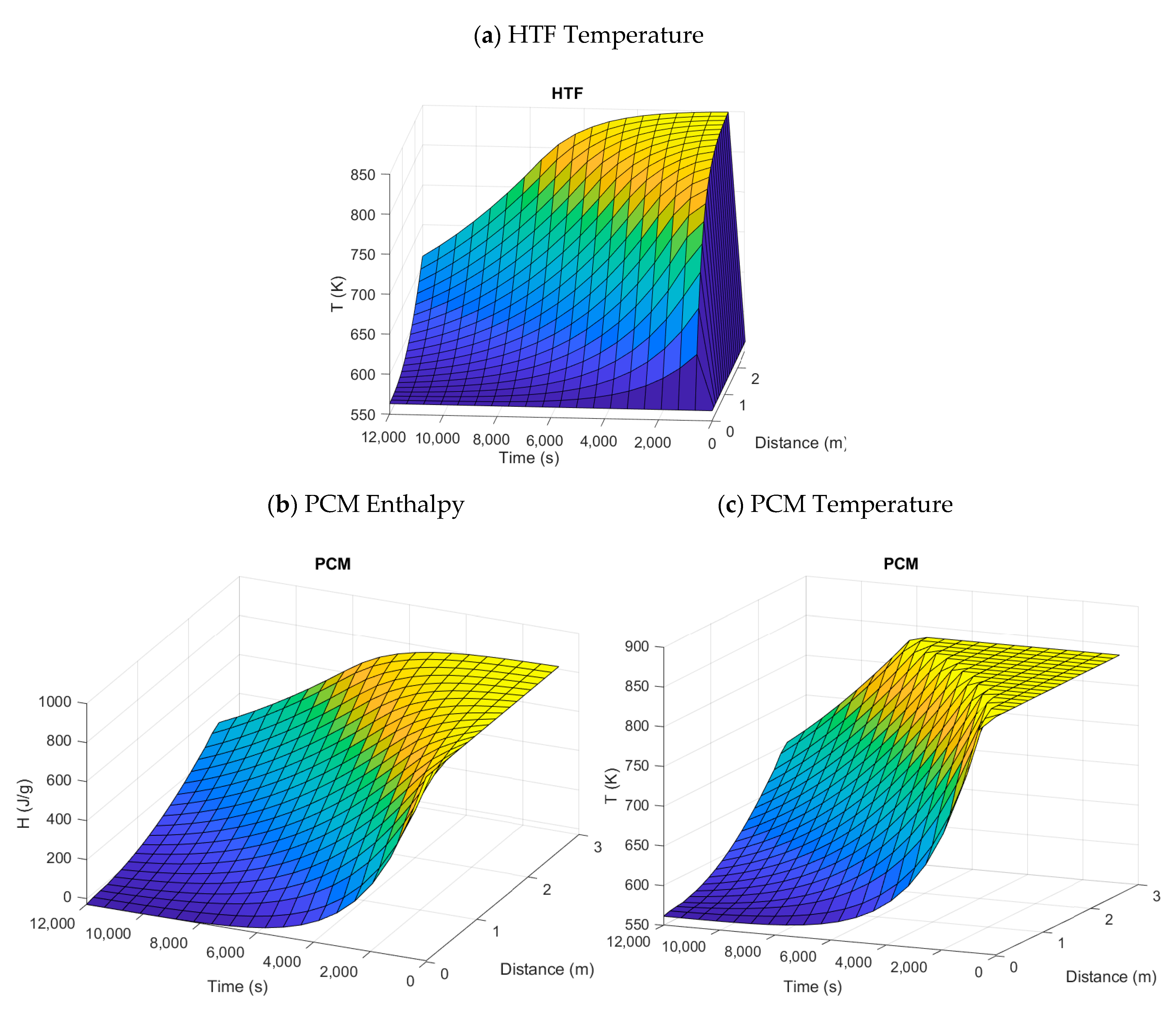
The simulation results for the discharging phase, obtained by using the Matlab pdepe function to solve the governing Equations (11) and (12) within a determined time and length (t, z), and with a 1-D mesh grid, are described in Figure 7. In particular, in Figure 7a, the HTF temperature is reported, while Figure 7b,c show, respectively, PCM enthalpy and temperature as a function of the discharging time and heat exchanger height.
Figure 7.
Surface plots of the heat exchanger fluid-dynamic simulation results: HTF temperature (a), PCM enthalpy (b) and PCM temperature (c) as a function of discharging time and heat exchanger height.
The modelling outcome highlights the release of sensible heat, along with latent enthalpy, especially in the first layers of the heat exchanger. This effect cannot be avoided and affects the thermal exchange efficiency between air and PCM, given heat is transferred at lower temperatures. The consequence is particularly evident after about 6000 s of discharging time, with a decrease in the air outlet temperature. Hence, in order to obtain the necessary input temperature for the user, a larger amount of PCM must be utilized, leading to an increase in the heat exchanger investment cost.
The storage efficiency can be determined as proposed by Li et al. [50] (16), where the numerator can be calculated by integrating the simulated curve of HTF temperature at the heat exchanger outlet versus the discharging time (t), while the denominator is the maximum theoretical outcome, related to unitary efficiency. A result of 0.77 was obtained, showing a good efficiency despite the non-ideal behavior of the thermocline system.
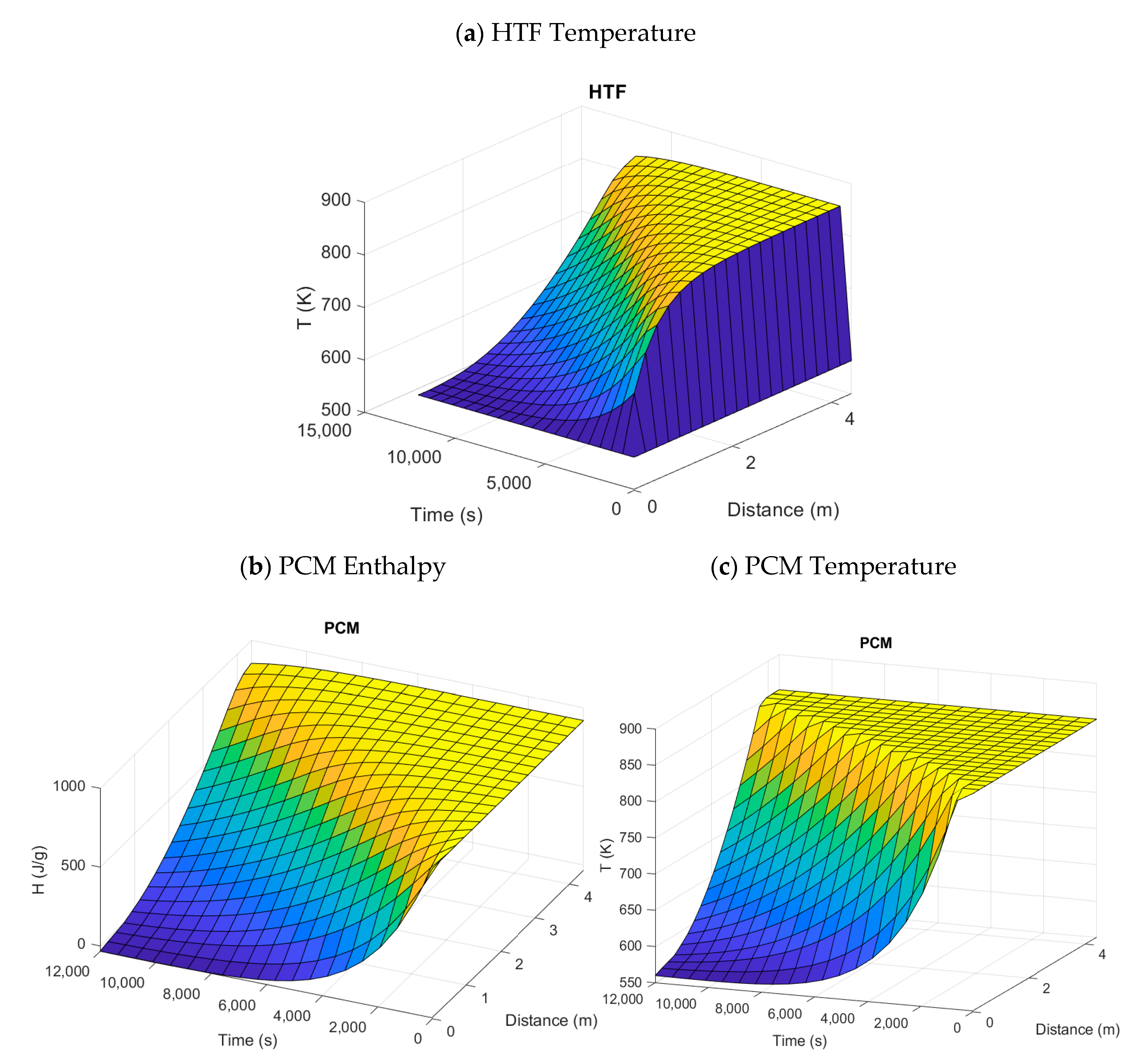
On the other hand, a more realistic practical way to calculate the storage efficiency is to consider the lowest packed bed necessary to obtain a constant HTF outlet temperature along the entire discharging time. The fluid-dynamic simulation shows that this can be achieved if the PCM height is increased up to 4.4 m (Figure 8). Actually, Figure 8 shows that after a small stabilization time the air exiting temperature maintains a stable value at 550 °C (823.15 K) practically over the whole discharging phase. The efficiency can be then defined as the ratio between the lowest, related to unitary efficiency, and the actual packed bed volume, resulting in a value of 0.6, which seems to describe more realistically the behavior of the storage system.
Figure 8.
Surface plots of the heat exchanger fluid-dynamic simulation increasing the height of the PCM encapsulated bed up to 4.4m: HTF temperature (a), PCM enthalpy (b), and PCM temperature (c) as a function of discharging time and heat exchanger height.
3.3. Cost Analysis
The tank cost, including stairs, platforms and the normal complements for the flow hardware was assessed by literature price tables [51]. Both stainless steel AISI 304 and 316L, along with carbon steel, ASTM A516 grade 70, were considered as construction materials. The cost, originally in dollars, was calculated in euros with an exchange rate of 1.13 USD/EUR and was updated at the present year using the updated equipment cost indexes (“Chemical Engineering Plant Cost Index: 2018 Annual Value—Chemical Engineering | Page 1” n.d.). The price of the PCM and the capsules was estimated by an online market search regarding the single salts and aluminum plates; the manufacturing additional cost, including encapsulation, was assumed at 25% of the material price. The storage efficiency calculated in the previous paragraph was as well taken into account to determine the oversize of encapsulated PCM and tank. The investment cost per thermal kWh resulted in a minimum calculated value of about EUR 25, which is quite consistent with the figures expected for high-temperature thermal storage [52]. At any rate, it is significantly lower than the value of EUR 40, presented nowadays by the two storage, sensible heat systems, based on molten salts [22,31] and in line with the Key Performance Indicators (KPI) [53]. Table 8 shows the breakdown of the packed bed heat exchanger investment costs.
Table 8.
Packed bed heat exchanger: investment cost analysis.
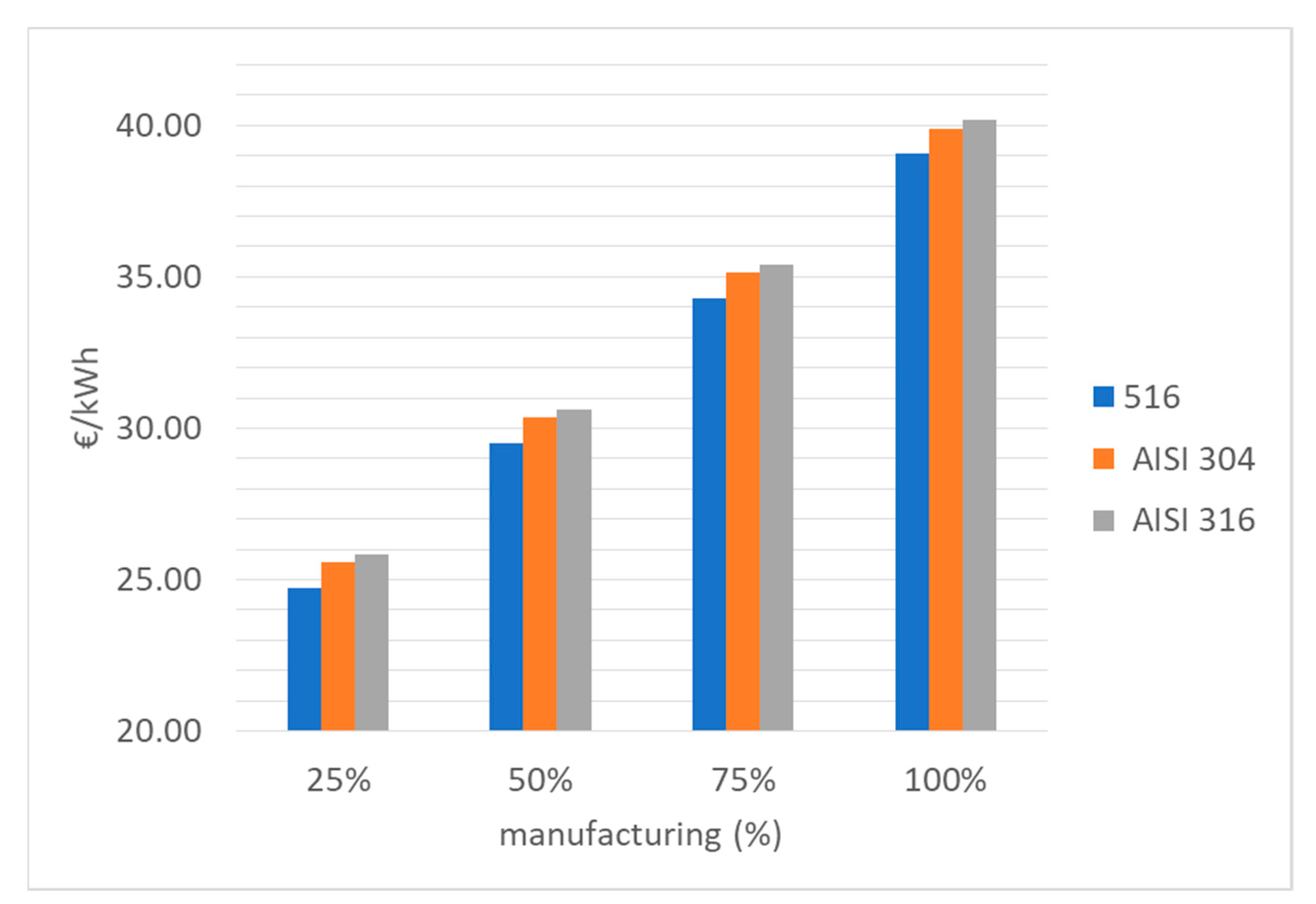
Considering that the estimation of the encapsulation costs cannot be quite accurate, a sensitivity analysis by varying the percentage attributed to the manufacturing of the PCM, from 25% to 100%, was carried out on the total cost per kWh for the three different types of steel considered, as reported in Table 9.
Table 9.
PCM manufacturing variation impact to the total costs.
It is thus possible to deduce that PCM encapsulation price strongly affects the trend of the total cost, as also shown in Figure 9.
Figure 9.
Investment cost analysis by varying PCM encapsulation cost percentage.
4. Conclusions
The present article aimed to evaluate the performances of a PCM storage system for high temperatures based on a direct heat exchanger.
Firstly, it was necessary to select a suitable phase change material, which has to comply not only with the necessary thermophysical features but also needs to present low toxicity and cost along with high availability. To this aim, an eutectic mixture formed by chlorides and carbonates was selected and experimentally characterized, and the results showed a transition temperature near 600 °C and a high capacity for heat accumulation due to a latent enthalpy of 195 kJ/kg and a density of about 2000 Kg/m3.
Among several possible configurations for a feasible heat exchanger, given the necessity to confine the PCM and considering a relative scarcity in the scientific literature about studies regarding packed bed with microcapsules, a tubular geometry with spherical encapsulation was selected and investigated.
The sizing of the heat exchanger was carried out using scalar one-dimension energy equations to simulate the fluid-dynamic behavior, setting the accumulation power and time, and considering a Rankine cycle as a power block. Then, the storage efficiency was calculated, obtaining a relatively good value of 0.6.
Finally, a cost analysis was performed, using realistic prices both for the PCM and the tank materials. The results are quite promising, showing high potential benefits for this technology. Evidently, the weak point of this evaluation is the scarcity of data about actual costs for the microencapsulation process, which is a key point for the suitability of this type of storage systems. For this reason, it can be stated that this issue needs to be thoroughly investigated in the next future in order to make the latent heat technology more efficient and dispatchable.
Author Contributions
Data curation, E.M. and A.D.L.; Formal analysis, T.D. and A.D.L.; Funding acquisition, R.L.; Investigation, V.T., N.C. and A.D.L.; Software, T.D.; Supervision, A.S. and M.C.; Writing – original draft, A.C.T., G.S.S., V.T., E.M. and A.D.L.; Writing – review & editing, R.L. All authors have read and agreed to the published version of the manuscript.
Funding
This research was funded by the Italian Ministry of Economic Development through the Research on Electric System—PTR 2019-21—Objective: Technologies—Project 1.2/WP2 (Thermal Storage).
Institutional Review Board Statement
Not applicable.
Informed Consent Statement
Not applicable.
Data Availability Statement
No external data excluding in the state of the art discussion.
Conflicts of Interest
The authors declare no conflict of interest.
Glossary
| Nomenclature | Units | |
| Density | ||
| Specific heat | ||
| Thermal conductivity | ||
| Void fraction of packed bed | ||
| Velocity | ||
| Convective coefficient of heat transfer | ||
| Convectivity factor | (1/m) | |
| Temperature | T | K |
| Time | t | s |
| Enthalpy | H | |
| Dynamic viscosity | Pa s | |
| Cross section area of the cylindrical tank | ||
| Reciprocal of thermal exchange coefficient | ||
| Thickness | s | (m) |
| Mass flow rate | (kg/s) | |
| Radius of capsule | r | (m) |
| Radius of tank | R | |
| Dynamic viscosity | Pa* s |
References
- IRENA Renewable Energy Statistics. Available online: https://www.irena.org/publications/2020/Jul/Renewable-energy-statistics-2020 (accessed on 24 August 2021).
- Sawin, J.L.; Martinot, E. Renewables bounced back in 2010, REN21. 2011. Renewables 2011 Global Status Report. Available online: https://www.ren21.net/wp-content/uploads/2019/05/GSR2011_Full-Report_English.pdf (accessed on 24 August 2021).
- Chu, Y.; Meisen, P. Review and Comparison of Different Solar Energy Technologies; Global Energy Network Institute (GENI): San Diego, CA, USA, 2011. [Google Scholar]
- Sharan, P.; Turchi, C.; Kurup, P. Optimal design of phase change material storage for steam production using annual simulation. Sol. Energy 2019, 185, 494–507. [Google Scholar] [CrossRef] [Scilit]
- Prieto, C.; Rodríguez, A.; Patiño, D.; Cabeza, L.F. Thermal energy storage evaluation in direct steam generation solar plants. Sol. Energy 2018, 159, 501–509. [Google Scholar] [CrossRef] [Scilit]
- Da Cunha, J.; Eames, P. Thermal energy storage for low and medium temperature applications using phase change materials—A review. Appl. Energy 2016, 177, 227–238. [Google Scholar] [CrossRef] [Scilit]
- Liu, D.; Xin-Feng, L.; Bo, L.; Si-Quan, Z.; Yan, X. Progress in thermochemical energy storage for concentrated solar power: A review. Int. J. Energy Res. 2018, 42, 4546–4561. [Google Scholar] [CrossRef] [Scilit]
- IEA. World Energy Outlook 2019—Analysis; IEA: Paris, France.
- Shuiqing, Z.; Ye, W.; Jiemin, Z.; Ying, Y.; Yannan, L.; Shujuan, L. Determination of thermal conductivity of inorganic salts at the liquid/solid phase transition point. In Proceedings of the 2013 Fourth International Conference on Digital Manufacturing & Automation, Qingdao, China, 9–30 June 2013; pp. 477–480. [Google Scholar]
- Zalba, B.; Marín, J.M.; Cabeza, L.F.; Mehling, H. Review on thermal energy storage with phase change: Materials, heat transfer analysis and applications. Appl. Therm. Eng. 2003, 23, 251–283. [Google Scholar] [CrossRef] [Scilit]
- Xu, B.; Li, P.; Chan, C.; Tumilowicz, E. General volume sizing strategy for thermal storage system using phase change material for concentrated solar thermal power plant. Appl. Energy 2015, 140, 256–268. [Google Scholar] [CrossRef] [Scilit]
- Sharma, A.; Tyagi, V.V.; Chen, C.R.; Buddhi, D. Review on thermal energy storage with phase change materials and applications. Renew. Sustain. Energy Rev. 2009, 13, 318–345. [Google Scholar] [CrossRef] [Scilit]
- Gomez-Vidal, J.; Tirawat, R. Corrosion of alloys in a chloride molten salt (NaCl-LiCl) for solar thermal technologies. Sol. Energy Mater. Sol. Cells 2016, 157, 234–244. [Google Scholar] [CrossRef] [Scilit]
- Forum, S.F.-M.S. Corrosion of Structural Materials in Molten Carbonate Fuel Cells: An Overview; Molten Salt Forum; Trans Tech Publications: Bäch SZ, Switzerland, 2003; Volume 7, pp. 135–154. [Google Scholar]
- Hoshi, A.; Mills, D.R.; Bittar, A.; Saitoh, T.S. Screening of high melting point phase change materials (PCM) in solar thermal concentrating technology based on CLFR. Sol. Energy 2005, 79, 332–339. [Google Scholar] [CrossRef] [Scilit]
- Li, Q.; Li, C.; Du, Z.; Jiang, F.; Ding, Y. A review of performance investigation and enhancement of shell and tube thermal energy storage device containing molten salt based phase change materials for medium and high temperature applications. Appl. Energy 2019, 255, 113806. [Google Scholar] [CrossRef] [Scilit]
- Delise, T.; Tizzoni, A.; Ferrara, M.; Corsaro, N.; D’Ottavi, C.; Sau, S.; Licoccia, S. Thermophysical, environmental, and compatibility properties of nitrate and nitrite containing molten salts for medium temperature CSP applications: A critical review. J. Eur. Ceram. Soc. 2019, 39, 92–99. [Google Scholar] [CrossRef] [Scilit]
- Lin, Y.; Alva, G.; Fang, G. Review on thermal performances and applications of thermal energy storage systems with inorganic phase change materials. Energy 2018, 165, 685–708. [Google Scholar] [CrossRef] [Scilit]
- Galione, P.; Perez-Segarra, C.-D.; Rodríguez, I.; Oliva, A.; Rigola, J. Multi-layered solid-PCM thermocline thermal storage concept for CSP plants. Numerical analysis and perspectives. Appl. Energy 2015, 142, 337–351. [Google Scholar] [CrossRef] [Scilit]
- Feldhoff, J.F.; Schmitz, K.; Eck, M.; Schnatbaum-Laumann, L.; Laing, D.; Ortiz-Vives, F.; Schulte-Fischedick, J. Comparative system analysis of direct steam generation and synthetic oil parabolic trough power plants with integrated thermal storage. Sol. Energy 2012, 86, 520–530. [Google Scholar] [CrossRef] [Scilit]
- Elfeky, K.; Ahmed, N.; Wang, Q. Numerical comparison between single PCM and multi-stage PCM based high temperature thermal energy storage for CSP tower plants. Appl. Therm. Eng. 2018, 139, 609–622. [Google Scholar] [CrossRef] [Scilit]
- Delise, T.; Tizzoni, A.; Menale, C.; Telling, M.; Bubbico, R.; Crescenzi, T.; Corsaro, N.; Sau, S.; Licoccia, S. Technical and economic analysis of a CSP plant presenting a low freezing ternary mixture as storage and transfer fluid. Appl. Energy 2020, 265, 114676. [Google Scholar] [CrossRef] [Scilit]
- Kuravi, S.; Trahan, J.; Goswami, D.Y.; Rahman, M.M.; Stefanakos, E.K. Thermal energy storage technologies and systems for concentrating solar power plants. Prog. Energy Combust. Sci. 2013, 39, 285–319. [Google Scholar] [CrossRef] [Scilit]
- Myers, P.; Goswami, D.Y. Thermal energy storage using chloride salts and their eutectics. Appl. Therm. Eng. 2016, 109, 889–900. [Google Scholar] [CrossRef] [Scilit]
- Ferrer, G.; Solé, A.; Barreneche, C.; Martorell, I.; Cabeza, L.F. Corrosion of metal containers for use in PCM energy storage. Renew. Energy 2015, 76, 465–469. [Google Scholar] [CrossRef] [Scilit]
- Regin, A.F.; Solanki, S.; Saini, J. Heat transfer characteristics of thermal energy storage system using PCM capsules: A review. Renew. Sustain. Energy Rev. 2008, 12, 2438–2458. [Google Scholar] [CrossRef] [Scilit]
- Schumann, T. Heat transfer: A liquid flowing through a porous prism. J. Frankl. Inst. 1929, 208, 405–416. [Google Scholar] [CrossRef] [Scilit]
- Ismail, K.; Henríquez, J. Numerical and experimental study of spherical capsules packed bed latent heat storage system. Appl. Therm. Eng. 2002, 22, 1705–1716. [Google Scholar] [CrossRef] [Scilit]
- Peng, H.; Dong, H.; Ling, X. Thermal investigation of PCM-based high temperature thermal energy storage in packed bed. Energy Convers. Manag. 2014, 81, 420–427. [Google Scholar] [CrossRef] [Scilit]
- Bellan, S.; Alam, T.E.; González-Aguilar, J.; Romero, M.; Rahman, M.M.; Goswami, D.; Stefanakos, E.K. Numerical and experimental studies on heat transfer characteristics of thermal energy storage system packed with molten salt PCM capsules. Appl. Therm. Eng. 2015, 90, 970–979. [Google Scholar] [CrossRef] [Scilit]
- Sau, S.; Corsaro, N.; Crescenzi, T.; D’Ottavi, C.; Liberatore, R.; Licoccia, S.; Russo, V.; Tarquini, P.; Tizzoni, A. Techno-economic comparison between CSP plants presenting two different heat transfer fluids. Appl. Energy 2016, 168, 96–109. [Google Scholar] [CrossRef] [Scilit]
- Ávila-Marín, A.L. Volumetric receivers in solar thermal power plants with central receiver system technology: A review. Sol. Energy 2011, 85, 891–910. [Google Scholar] [CrossRef] [Scilit]
- Good, P.; Zanganeh, G.; Ambrosetti, G.; Barbato, M.; Pedretti, A.; Steinfeld, A. Towards a commercial parabolic trough CSP system using air as heat transfer fluid. Energy Procedia 2014, 49, 381–385. [Google Scholar] [CrossRef] [Scilit]
- Pitz-Paal, R.; Jürgen, D.; Milow, B. (Eds.) SES6-CT ECOSTAR. European Concentrated Solar Thermal Deliverable No. 7 Roadmap Document. Available online: https://www.vgb.org/vgbmultimedia/roadmap252-p-1723.pdf (accessed on 24 August 2021).
- Boretti, A.; Castelletto, S.; Al-Zubaidy, S. Concentrating solar power tower technology: Present status and outlook. Nonlinear Eng. 2018, 8, 10–31. [Google Scholar] [CrossRef] [Scilit]
- Reyes-Belmonte, M.A.; Pino, F.J.; Romero, M.; Suarez, C.; González-Aguilar, J.; Guerra, J. Optimization of an integrated solar combined cycle. AIP Conf. Proc. 2018, 2033, 210012. [Google Scholar] [CrossRef] [Scilit]
- Lanchi, M.; Turchetti, L.; Sau, S.; Liberatore, R.; Cerbelli, S.; Murmura, M.A.; Annesini, M.C. A Discussion of possible approaches to the integration of thermochemical storage systems in concentrating solar power plants. Energies 2020, 13, 4940. [Google Scholar] [CrossRef] [Scilit]
- Ellingwood, K.; Safdarnejad, S.M.; Rashid, K.; Powell, K. Leveraging energy storage in a solar-tower and combined cycle hybrid power plant. Energies 2018, 12, 40. [Google Scholar] [CrossRef] [Scilit]
- Kruizenga, A.M. Corrosion Mechanisms in Chloride and Carbonate Salts; Report No. SAND2012-7594; Sandia National Laboratories: Livermore, CA, USA.
- Yaokawa, J.; Oikawa, K.; Anzai, K. Thermodynamic assessment of the KCl–K2CO3–NaCl–Na2CO3 system. Calphad 2007, 31, 155–163. [Google Scholar] [CrossRef] [Scilit]
- Tumilowicz, E.; Chan, C.L.; Li, P.; Xu, B. An enthalpy formulation for thermocline with encapsulated PCM thermal storage and benchmark solution using the method of characteristics. Int. J. Heat Mass Transf. 2014, 79, 362–377. [Google Scholar] [CrossRef] [Scilit]
- Van Lew, J.; Li, P.; Chan, C.L.; Karaki, W.; Stephens, J. Analysis of heat storage and delivery of a thermocline tank having solid filler material. J. Sol. Energy Eng. 2011, 133, 021003. [Google Scholar] [CrossRef] [Scilit]
- Xu, B.; Li, P.; Chan, C. Application of phase change materials for thermal energy storage in concentrated solar thermal power plants: A review to recent developments. Appl. Energy 2015, 160, 286–307. [Google Scholar] [CrossRef] [Scilit]
- Gage, S.; Sharan, P.; Turchi, C.; Netter, J. Evaluation of formate salt PCM’s for latent heat thermal energy storage. Energies 2021, 14, 765. [Google Scholar] [CrossRef] [Scilit]
- Andersson, P. Thermal conductivity under pressure and through phase transitions in solid alkali halides. I. Experimental results for KCl, KBr, KI, RbCl, RbBr and RbI. J. Phys. C: Solid State Phys. 1985, 18, 3943–3955. [Google Scholar] [CrossRef] [Scilit]
- Deng, Z.F.; Liu, Z.H.; Zhang, G.Q.; Xu, G.Z.; Yang, C.Y. Effect of humidity environment on properties of molten salt phase change materials. In Proceedings of the IOP Conference Series: Materials Science and Engineering, the 2nd International Workshop on Materials Science and Mechanical Engineering (IWMSME2018), Qingdao, China, 26–28 October 2018; IOP Publishing: Bristol, UK, 2019; Volume 504, p. 012010. [Google Scholar]
- Perry, R.H.; Green, D.W. Perry’s Chemical Engineers’ Handbook; McGraw-Hill: New York, NY, USA, 2008. [Google Scholar]
- Romero, M.; Buck, R.; Pacheco, J.E. An update on solar central receiver systems, projects, and technologies. J. Sol. Energy Eng. 2002, 124, 98–108. [Google Scholar] [CrossRef] [Scilit]
- Rhodes, M. Introduction to Particle Technology; John Wiley & Sons: Hoboken, NJ, USA, 2008. [Google Scholar]
- Li, P.; van Lew, J.; Chan, C.; Karaki, W.; Stephens, J.; O’Brien, J. Similarity and generalized analysis of efficiencies of thermal energy storage systems. Renew. Energy 2012, 39, 388–402. [Google Scholar] [CrossRef] [Scilit]
- Peters, M.; Timmerhaus, K.; West, R. Plant Design and Economics for Chemical Engineers, 5th ed.; McGraw-Hill: New York, NY, USA, 2003. [Google Scholar]
- IEA-ETSAP; IRENA©. Technology Brief E17—Thermal Energy Storage-Technology Brief-January 2013; IEA-ETSAP; IRENA©; Available online: https://www.irena.org/publications/2013/Jan/Thermal-energy-storage (accessed on 24 August 2021).
- Cabeza, L.F.; Galindo, E.; Prieto, C.; Barreneche, C.; Fernandez, A.I. Key performance indicators in thermal energy storage: Survey and assessment. Renew. Energy 2015, 83, 820–827. [Google Scholar] [CrossRef] [Scilit]
Publisher’s Note: MDPI stays neutral with regard to jurisdictional claims in published maps and institutional affiliations. |
© 2021 by the authors. Licensee MDPI, Basel, Switzerland. This article is an open access article distributed under the terms and conditions of the Creative Commons Attribution (CC BY) license (https://creativecommons.org/licenses/by/4.0/).