2. Deploying Clock Synchronization on a Network
Clock synchronization on a network is typically deployed with a common set of requirements: a reliable clock source, a medium to convey the precise clock information, and a common understanding of how to interpret that information. The first requirement, a reliable clock source, indicates that there must be some initial source of the clock information on the network. For modern applications, this is usually some form of reference clock, such as a reference clock at an appropriate national standards organization or a commonly available and agreed-upon source of timing information. The clock source should have the appropriate reliability and accuracy needed for applications that require clock synchronization. In practice, the source of time is usually a Global Navigation Satellite System (GNSS) receiver, such as a GPS receiver.
With a reliable clock source, the medium to convey the precise clock information forms the network. The network is a very loose term here and includes things such as over-the-air point-to-point transmissions, a general over-the-air broadcast, or even the more direct definition in an electrical connection between one or more points (e.g., Ethernet or fiber network). The network provides the connection to move the reliable clock information out to applications and devices that must use it.
With a reliable clock and a physical way to convey the information available, a common understanding of how to interpret the clock information is needed (i.e., a standard). This includes the overall formatting of the clock information (i.e., how it is encoded) and common information on how often the clock signal is expected or how to determine the latency of the information transmission. This is accomplished with the clock synchronization protocol.
2.1. The Clock Synchronization Protocol
The purpose of a clock synchronization protocol is to communicate time information through a network; it provides a mechanism for distributed devices to agree on the time of day. Often, but not always, the networked devices are synchronized with either Coordinated Universal Time (UTC) or International Atomic Time (TAI). Usually, a single end-point in the network acts as the source of time, and a predefined protocol is used to transfer that time through various switches/routers to other endpoints. The result is that everything in the network operates with the same time. For modern electric power grid applications, this common time frame is needed for proper measurement, control, and protection. Ethernet is a common network technology employed by time-aware networks, but other networks are applicable, such as WiFi and 5G. More advanced protocols also include ways to integrate multiple clock sources to coordinate and improve the overall precision and accuracy of clock synchronization deployed over a network.
Why is a protocol needed? To help answer that question, consider an example implementation of a clock in a device. The device’s clock hardware comprises an oscillator that is specified as 100 million ticks per second (100 MHz). Software in the device reads a counter that tells it how many ticks have occurred since the oscillator was powered on. Without any other information, the software does not know what time it is. If the device has a network connection, it can receive time from another device over the network. For devices to synchronize time accurately, it is insufficient to use a simple message that contains the current time because the time changes as the message travels over the network. Additionally, oscillators are imperfect; in reality, one device’s 100 MHz oscillator could run at 99.990 MHz, and another device’s oscillator could run at 100.010 MHz. This kind of discrepancy can cause times to eventually drift apart, and that drift is affected by environmental factors such as temperature. The clock synchronization protocol operates continuously to resolve these challenges.
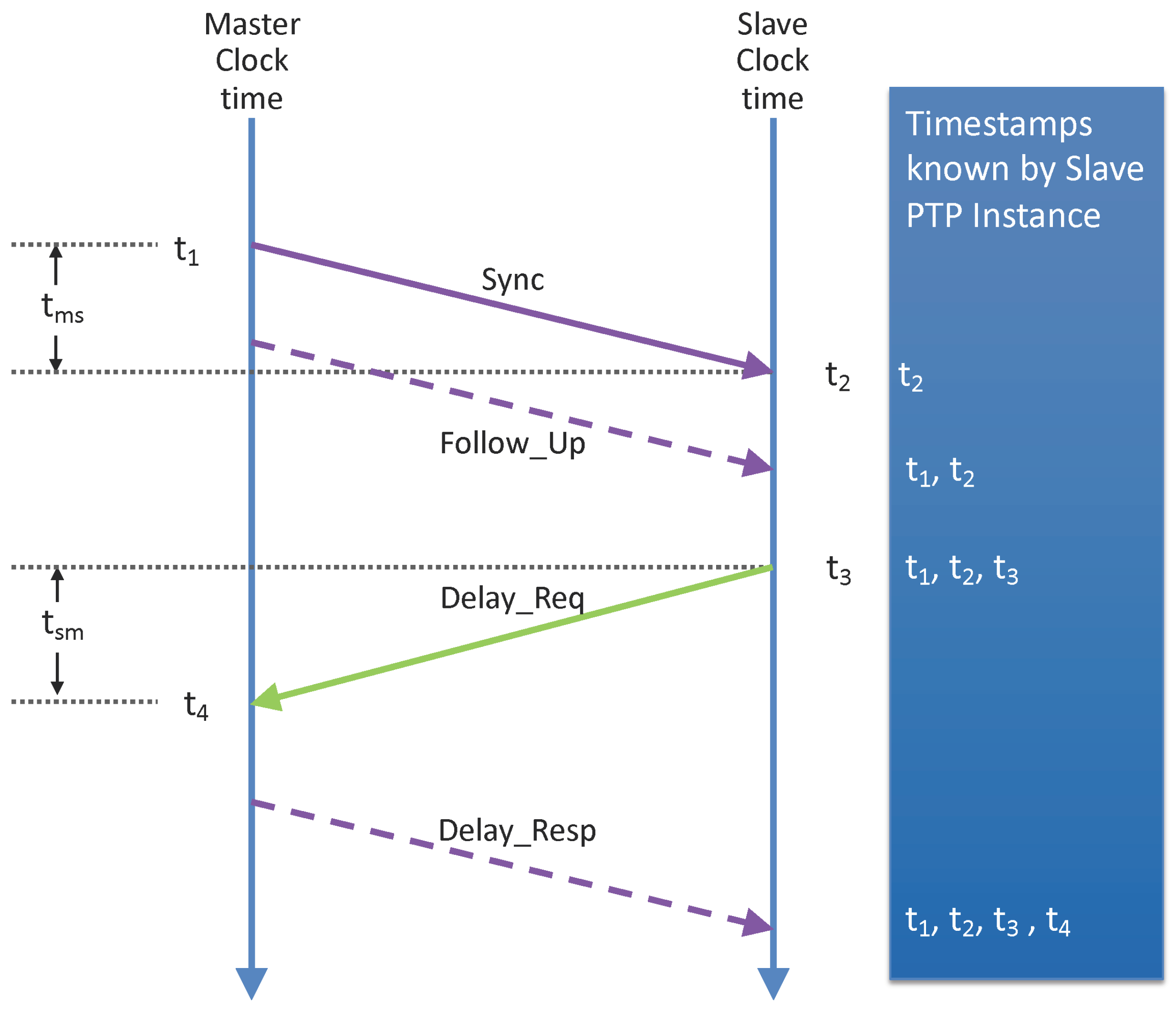
A clock synchronization protocol can be complex, but
Figure 1 illustrates the fundamentals. Our example uses the PTP, and carefully chosen numbers were selected to simplify the figure. The goal of the protocol is to find the offset (i.e., difference) between two clocks: the
master clock and the
slave clock. At a specific moment in time, the master clock is at 19 December 2020, 08:05:00.000001000 (8:05 a.m. and 1000 ns) and the slave clock is at 19 December 2020, 08:05:00.000004000 (8:05 a.m. and 4000 ns). For simplicity, only nanoseconds are used (1000 and 4000 ns). The master clock and slave clock communicate over a CAT5 copper Ethernet cable. The time for a single bit to propagate over CAT5 is 2 ×
m/s. A cable between the master clock and slave clock is assumed to be 10 m long and thus has a 50 ns propagation time.
Each time a PTP message is transmitted or received, a timestamp is acquired at a specific point in the message by using the oscillator counter. In
Figure 1, the master clock acquires timestamp t
1 when a specified bit of the sync message transmits at the connector. Assume that t
1 is 1000 ns. The slave clock acquires timestamp t
2 when the same bit of the sync message is received at its connector. Assume that t
2 is 4050 ns. The slave clock does not know t
1 yet because the master clock did not know t
1 until after the sync message transmitted. The master clock resolves this by sending t
1 in the contents of a
Follow_Up message. The dotted line for the
Follow_Up message indicates that the message is not timestamped, but is used to transport a timestamp value. At this point, the slave clock can calculate (t
2–t
1),also known as
tms. The t
ms value of 3050 ns is insufficient to find the clock offset. The t
ms value is the clock offset (3000 ns) plus the propagation time (50 ns), and the slave clock cannot distinguish between the two components.
The Delay_Req and Delay_Resp messages are used to find the propagation time. The slave clock transmits a Delay_Req to the master clock, acquiring timestamp t3. Assume that t3 is 305,000 ns. The master clock acquires timestamp t4 when Delay_Req is received, and the master clock sends t4 back to the slave clock in the Delay_Resp message. Assume that t4 is 302,050 ns. The slave clock can calculate (t4–t3), also known as tsm, which is −2950 ns for this example. The PTP assumes that the propagation time is the same in each direction (i.e., symmetric). Therefore, the propagation time is calculated as , which is (3050−2950) / 2 = 50 ns for this example. Now that the PTP knows the propagation time, the PTP can calculate the clock offset as , or 3000 ns. When the slave clock subtracts the clock offset from its local time, it is accurately synchronized with the master clock time.
2.2. Several Notable Clock Synchronization Protocols
The PTP is certainly not the only clock synchronization protocol one might encounter. Other popular protocols include the Inter-Range Instrumentation Group (IRIG) [
12], the NTP [
13], and the Simple Network Time Protocol (SNTP) [
14].
IRIG timecodes are standard formats for transferring timing information [
12]. The main difference among the various IRIG codes is their rate, which varies between one pulse per minute and 10,000 pulses per second. For instance, IRIG-B has a frame rate of 1 Hz.
The NTP is perhaps one of the best-known clock synchronization systems [
13]. The NTP uses a hierarchical system of clocks in which the highest level,
stratum 0, is considered the reference and is, in practice, typically comprised of atomic clocks or GPS clocks. A device in the network usually synchronizes its local clock against one or more clocks in the same stratum or against the stratum one level higher. An important property of the NTP is that the time is transferred through the data network. This distinguishes the NTP from time distribution technologies, such as IRIG timecodes, which require grid operators to install and maintain dedicated timing cables. If the remote clocks are accessed over the public Internet, then the device can usually maintain its clock to within 10 ms of the reference clock; time uncertainties of 1 ms are possible if a time server is available on the local intranet. Hierarchical approaches trade scalability for relaxed tolerance to variance: each leaf node is no longer necessarily synchronized with the stratum 0 reference, and there is no guarantee that the stratum 0 reference is exactly synchronized with lower level strata (only the NTP protocol itself). Mills provided a survey of the characteristics of roughly 10,000 machines on the Internet [
15]. Offset error distributions for several protocols show results that range from multiple milliseconds to times exceeding 100 s. As will be discussed in
Section 5, modern power systems often require timing accuracy in the microsecond range, so even a best-case NTP implementation will not provide the accuracy needed for such applications.
The SNTP is a less complex implementation of the NTP suitable for deployments that do not require the NTP’s level of accuracy. The SNTP is designed to coexist with existing NTP and SNTP clients and servers. It is often used in embedded systems and applications in which full NTP capability is not required [
14].
The PTP, IEEE Standard 1588, has superseded the NTP in applications that require a precise clock for networked systems [
11]. As for the NTP, the PTP allows the data network to serve double duty as the time distribution infrastructure. The PTP is typically used in conjunction with hardware support. The idea of the PTP is to use additional timestamps to remove delay uncertainties and thereby improve time agreement. Compliant networks should be able to achieve uncertainties in well under 1
s. The accuracy of the clock synchronization is affected by multiple factors, including (1) the accuracy of the timestamping at the correct point in a message and (2) the symmetry of the propagation time. The PTP provides a variety of features to customize the implementation of these factors and other aspects. Because different applications (e.g., telecommunications network, network in a car) have different requirements, the concept of the PTP Profile was created. The PTP Profile documents the customization of a specific application, such as requiring some features that are optional in IEEE 1588 and/or prohibiting some features that are not needed. Over the years, this PTP Profile concept has been one of the primary reasons for the IEEE 1588 standard’s success because many applications have adapted the PTP to their requirements. This has resulted in a wide range of PTP Profiles that cover different applications. One of the aims of IEEE 1588-2019 has been to introduce features that align with these PTP Profiles.
2.3. General Use Cases
Time synchronization protocols have long been used within the scientific laboratory setting. The European Organization for Nuclear Research (CERN) is one of the world’s largest and most respected research organizations. CERN is home to the Large Hadron Collider (LHC), which accelerates particles around a 27 km ring and uses a large Ethernet network for time synchronization (the required time synchronization performance is subnanosecond). As a result of those requirements, and in cooperation with other scientific research organizations, CERN developed a PTP Profile called White Rabbit. White Rabbit specifies many innovative techniques, such as enhancements for the use of Ethernet hardware clocks and the calibration of asymmetry in fiber-optic cabling. The specifications from White Rabbit are incorporated into a new PTP Profile called the High-Accuracy Delay Request-Response Default PTP Profile and specified in the IEEE 1588-2019 document. This profile formalizes White Rabbit as part of the IEEE 1588 standard, which helps bring best-in-class performance to any application, including nonscientific applications such as electric power grid measurement and control.
Time synchronization is also heavily used within the telecommunications industry. Most people understand that devices are connected to the Internet via an Ethernet cable (e.g., to a WiFi router). What is sometimes lesser known is that telecommunications service providers implement a large network outside of their customers’ homes and offices, and this network is often Ethernet as well. Similar Ethernet networks exist within a 4G/5G base station to transfer mobile phone data to and from the Internet. These telecommunications networks require time synchronization, for which they use the PTP. The ITU is one of the world’s largest standardization organizations for telecommunications service providers, and its Telecommunication Standardization Sector (ITU-T) specifies multiple PTP Profiles. Past ITU-T standards specified the storage of performance statistics in logs with local measurement in 15 min and 24 h periods that were accessible at any time by a remote management client. The ITU-T’s past logging standards were unrelated to the PTP. Nevertheless, during the development of IEEE 1588-2019, experts from the ITU-T helped specify this sort of logging for the PTP. These specifications meet the needs of the ITU-T, but also bring the benefit of the ITU-T’s significant expertise to other applications. This work resulted in the specifications of the performance monitoring feature published within IEEE 1588-2019.
The advent of smart cars is placing the auto industry at the forefront of timing technology. IEEE 802 is a family of standards for local-area networks, such as Ethernet (IEEE 802.3) and WiFi (IEEE 802.11) technologies. As part of that family, the IEEE 802.1 Working Group specifies a PTP Profile within IEEE 802.1AS—Timing and Synchronization for Time-Sensitive Applications standard. The PTP Profile in IEEE 802.1AS is well known for providing a cost/performance trade-off that is an excellent fit for time-sensitive applications. Two examples of time-sensitive applications are the network inside a self-driving car and the network on a factory’s production floor. For a self-driving car, devices read input data from the physical world (e.g., radar and cameras to detect objects in front of a car), perform computations on that data, and generate output back to the physical world (e.g., steer the car). These in-vehicle devices communicate over a network, and the devices must be synchronized in time, which is when IEEE 802.1AS is applicable. The factory automation example is similar. Robots on the factory floor read input data (e.g., “Is there a bottle in front of me?”), perform computations, and generate output data (e.g., fill the bottle with the factory’s sparkling water). The devices on the factory floor are networked and time synchronized, and IEEE 802.1AS fulfills their requirements. In both time-sensitive examples, there is a strong need for IEEE 802.1AS time synchronization to run continuously, even when there is a physical fault, such as a broken wire. For an industrial factory, lost production time means lost revenue. For a self-driving car, synchronization loss could result in safety hazards. To meet these reliability requirements, the multiple domain feature was added to PTP standards. For example, assume that there are two distinct instances of the PTP protocol (i.e., domains) running in the network. Each domain has a different grandmaster (i.e., source of time) that sends time along different paths through the network as much as possible. Each end-point (i.e., destination of time) uses both domains simultaneously so that if either domain fails, everything continues to be synchronized. Requirements for multiple domains arose during the development of the new revision of the PTP Profile in IEEE 802.1AS-2020. Support for multiple domains required some architectural changes to the PTP. As a result, both IEEE Working Groups coordinated closely to add multiple domain support in IEEE 1588-2019 and IEEE 802.1AS-2020.
In live television shows, such as news programs, there are many seamless transitions from one scene to another, and the audio is synchronized with the video. Historically, television studios used direct audio/video cabling, but over time, many studios have transitioned to using Ethernet networking. In the context of Ethernet, the audio often travels in separate messages from the video. Time synchronization is important for these studio networks to precisely control their audio and video. The Society of Motion Picture and Television Engineers (SMPTE) specifies a PTP Profile for this application (ST 2059-2:2015). As for all Ethernet networks, SMPTE’s network consists of many switches that transfer messages between end-points (e.g., computers). Each switch supports a variety of protocols, and these protocols must be configured and updated, typically by IT personnel. Because each switch could come from a different company, the ideal mechanism to configure these switches is a standard that is not vendor-specific. The Internet Engineering Task Force provides standards for this purpose, such as the Simple Network Management Protocol (SNMP) and the Network Configuration Protocol (NETCONF). IEEE 1588-2008 specified a PTP-specific protocol for PTP configuration in a switch. Although the PTP is an important protocol, it is not the only protocol in an Ethernet switch. Organizations such as SMPTE need the ability to configure PTP in a switch by using protocols such as SNMP and NETCONF. As a result, the new revision of IEEE 1588-2019 contains architectural changes that significantly clarify and improve the ability to configure the PTP using SNMP and/or NETCONF. Using IEEE 1588-2019 as a foundation, work is ongoing in SMPTE and other PTP Profile organizations to establish a clear road map for PTP configuration into the future.
Financial trading firms build large networks that span multiple cities, and—owing to government regulations and other reasons—the trading actions in each city must be accurately time synchronized. Stock and equity trades are usually now made by automated systems instead of humans. The speed of automation means that prices change very rapidly so trading computers must be able to respond, with low time latency, before financial conditions change. As a result, it is often desired that PTP messages that are of interest to only a specific PTP device be sent as a unicast message rather than to one of the shared PTP multicast addresses. That way trading computers never waste time determining that a PTP message is not relevant. The result is that it is a common practice in the finance industry to send some PTP messages as multicast, and others as unicast. The IEEE 1588-2019 specifies enhancements and clarifications for mixing multicast and unicast communication in a single PTP network. These multicast/unicast clarifications will make it easier for other industries to make use of this PTP communication mode.
2.4. How Clock Synchronization Protocols Are Used in the Grid
For power systems, utilities must coordinate power device operations over a very large scale while maintaining the integrity of power delivery. Often, these power systems are built from many different technologies, which are operating in a wide range of environments. The most important criteria for power management are reliability, longevity, and low costs. Reliable timing accuracy is critical in power system operation, protection, and maintenance. Thus, clock synchronization protocols are very important in maintaining reliable timing accuracy among components in power systems. In many modern power system applications, differences in the phase angle of the electrical signal contain significant information and are explicitly used in the reliable control and protection of the power system. This phase angle calculation requires all devices to be synchronized to a common reference time within a required accuracy.
Given the heterogeneity of devices and applications associated with operating the power grid, the variety of synchronization protocols is also vast. One of the simplest clock synchronization protocols is the operating frequency of the power grid itself. Many clocks and timing systems, in particular older and less precise clocks, leverage the nominal grid frequency (e.g., 60 Hz in North America) as a simple synchronization/alignment signal; the clocks are built on the assumption that a set number of cycles of AC voltage will occur in 1 s. During normal power operations, the grid frequency actually fluctuates around the nominal value. Most power systems continue to maintain a “time-error-correction” clock, which accumulates the error over the course of the day and provides a correction to keep these simpler clocks properly synchronized.
For more precise time synchronization, rigorous time-related protocols are used in the power system. For remote devices that have lower precision requirements, time synchronization via the WWVB radio synchronization signal from the National Institute of Standards and Technology can be used. If data connections are available and precision is only needed on the order of a few milliseconds, NTP and SNTP can be deployed to synchronize remote devices. In the power system, these devices will either be noncritical power system measurements (e.g., weather) or lower-speed events (e.g., market pricing signals, physical security notifications).
For power system control activities, especially regarding protection, more precise time synchronization is needed. Power system protection often requires comparing measurements or conditions in tens of milliseconds or less on the order of cycles of the nominal frequency. In the North American system operating at 60 Hz, a single cycle is approximately 16 ms, so 1.0 of phase shift is approximately 46 s. Many applications depend on phase measurements at subdegree precision and accuracy, going below even this 46 s value. Differential line relays often use clock synchronization to compare phase measurements at different ends of a transmission line to help detect faults and de-energize the lines to prevent equipment damage or danger to people or property. These devices often only synchronize to each other over dedicated networks using propriety protocols, but still require a common clock to compute these phase angle differences.
For wide-area measurements and control, clock synchronization protocols are a key element. Phasor Measurement Units (PMUs) are wide-area measurement devices on the power system that coordinate to a central clock, often UTC time. This allows geographically disperse measurements to all be aligned and evaluated properly without worrying about the impacts of network delays. As alluded to several times, the phase angles of these phasor measurements are of particular interest and are especially dependent on the geographically dispersed devices all using a common reference time. Most deployed PMU devices use GPS or other GNSSs to provide a synchronizing clock. The GNSS-originated signal is often communicated to the power system measurement and control devices via the IRIG-B protocol, first developed in 1960 [
12]. Because of special cable requirements, additional timing requirements, and more devices requiring precision time in a power system substation, this widely used approach is gradually being replaced by the PTP in modern power system applications.
Although GPS and other GNSS sources are nearly ubiquitous as sources of clock synchronization, they are low-power signals that can be subject to forms of interference. As more power system applications rely on measurements from PMUs and faster devices, other clock synchronization approaches are being used. Properly deployed, the IEEE 1588-2019 PTP is being examined as a way to integrate GNSS sources and other trusted, precise clock sources into a timing architecture. This provides backup timing sources and overall robustness to the precision time synchronization required for accurately measuring the power system conditions (especially the phase angle)—metrics that are used to inform reliable and efficient control of geographically large power systems.
Sensors, such as instrument transformers, are used to isolate or transform voltage and current levels in power systems to obtain system-relevant metrics, including current, voltage, power, frequency, and power factor. These transformers are typically used with relays, which are actuating devices (referred to as actuators here) to protect the power systems. The sensor output comprises samples communicated to intelligent electronic devices for data collection, processing, and examination, which inform the system to take appropriate actions in response. For example, one response might be actuating a relay to protect the power system, commonly referred to as protective relay application. As sensors and actuators become smarter as technologies and standards advance, standardization such as the smart sensor system concept is developed. This includes standardizing time-synchronized sensing and actuation, as those components are essential for optimizing system performance and reliability in power grid operation.
The IEEE Power and Energy Society, Power System Instrumentation and Measurements Standards Committee’s P2681 standards working group is developing a standards project, “Guide for Testing Medium Voltage Smart Grid Sensor and Intelligent Electronic Device Systems” [
16]. A smart sensor systems diagram is being developed to show the functional elements of the systems, including time synchronization capability (
Figure 2). Smart sensor systems enable the so-called “smart grid”, and time-synchronized smart sensor and actuator systems will play key roles in future smart grids. Such technologies provide the means for wide-area monitoring and control of smart grids to bring about more efficient, reliable, and resilient power grid system operations.
3. Challenges Associated with Grid Timing
This section describes the impetus behind several active research areas in timing and synchronization. Attention is focused on how timing technology is being applied within power grids. In each instance, emerging needs are giving rise to new technologies and timing strategies.
3.1. Grid Application Timing Requirements
Given the enormous complexity and importance of a nationwide power grid, a correct understanding of the condition and events surrounding the operation of the grid is indispensable. An interesting question emerges: What is the impact of error in the provided time or position associated with power grid sensor data? Issues to be considered include discontinuities (e.g., leap seconds), uptime, and the properties of the time uncertainty. Moreover, the deployment of a timing solution must consider how the timing signal is propagated (e.g., WiFi, fiber, existing power lines), whether the solution is interoperable and backward-compatible with legacy systems, the security of the timing signal (e.g., spoof-proof, jamming resistant, provisions for authentication verification), and cost factors (both one-time costs at installation and recurring costs throughout the solution’s lifetime).
Emerging analysis and control activities on the power grid require stringent timing performance to achieve accurate detection and fault location. In PMU devices, the IEC/IEEE 60255-118-1:2018 Standard for Synchrophasor Measurements for Power Systems dictates many of the requirements for the phasor measurements, especially for accurately representing the phase angle values. The standard specifies a 1% Total Vector Error (TVE) for synchrophasors [
18]. From a timing accuracy perspective, this requires the time to be accurate within
26.5
s for a 60 Hz system, assuming only angle error. However, the standard recommends a time source at least 10-times as accurate (
2.6
s for a 60 Hz system) to ensure other contributors to measurement inaccuracy remain below the 1% TVE limit, typically accurate to around 0.022 [
19,
20]. For devices such as traveling wave fault locators, the timing requirements are often 1.0
s or less. The measurements from these devices help locate faults in the power grid by timing waveforms that travel down power lines at velocities near the speed of light. Because the high-voltage towers are spaced about 300 m apart, the timing requirement is 1
s or the period of a 300 m wavelength (to help track fault locations down to individual tower segments).
Industry requirements and technical interoperability standards have been established for the power grid and often dictate additional timing requirements [
21]. The IEC/IEEE 60255-118-1:2018 standard mentioned above requires a maximum of 1% of TVE, but suggests going well beyond this requirement. The IEC/IEEE 61850 standard for electric substation automation covers a wider range of devices and includes mechanisms to record and communicate the measurements with accurate timing information. System reliability standards, such as the North American Electric Reliability Corporation (NERC) PRC-002-2 standard for disturbance monitoring and reporting, may also drive timing requirements. In this particular case, NERC PRC-002-2 requires disturbance data to have a timestamp accurate to within
2 ms of UTC [
22], which IEC/IEEE 60255-118-1:2018 greatly exceeds by requiring at least
26
s for 1% TVE (and recommending
2.6
s).
Although phase angle measurements over larger geographic areas have been mentioned as a key timing-dependent measurement, the time-synchronized measurements of the power system have many applications. A 2018 technical report by the North American SynchroPhasor Initiative itemized 21 power grid-oriented applications and their timing requirements. Among these applications are small-signal stability monitoring, voltage stability monitoring, thermal monitoring, frequency stability monitoring, remedial action schemes, and state estimation. The required precision for these applications is 0.5
[
23] or approximately 23
s on a 60 Hz nominal system.
3.2. Consequences of Incorrect Timestamps and Late-Arriving Data
Precision timing is crucial among the many segments that comprise the U.S. power grid. Beyond the common reference time needed for phase angle measurements, cybersecurity is also extremely dependent on precise timing. Cybersecurity requires dynamic capabilities that can provide precise and accurate time to address advanced uses, including certificate and key management, blockchain capabilities, telecommunications integration, and accurate timestamps for grid sensors, all of which require precise and robust sources of time. Therefore, grid timing is a strategic area of research within the U.S. Department of Energy for grid modernization and secure grid operation. Sensor units, including PMUs and Supervisory Control and Data Acquisition (SCADA) units, are synchronized to coordinated UTC time to measure voltage and current waveforms (especially relative angles), calculate timestamps, and send measurements. Moreover, photovoltaic cells, wind farms, and microgrids are placing additional burdens on control and automation, which are becoming increasingly dependent on expanded coordination demands and synchronized time. The cybersecurity aspects of precise time extend beyond the power grid (e.g., U.S. Department of Homeland Security with critical infrastructure, U.S. Department of Transportation with secure vehicles and airplanes) and many civilian industries, including finance and communications. Currently, all of these diverse use cases depend heavily on GPS-based solutions that do not meet today’s cybersecurity needs.
The consequences of incorrect timestamps and late-arriving data are vitally important to the power grid. Timing errors cause false conclusions about grid conditions, which could lead to the misdiagnosis of system problems, incorrect responses to address those problems, and the shutdown or misoperation of grid assets. The Bonneville Power Administration reports that in one instance, “a bad GPS signal and cheap receiver led to the loss of two 500 kV lines, one 40 miles, the other 80 miles long” [
19].
3.3. Problems with Current Precision Time Delivery
Incorrect timing data can assume many different forms. For instance, if the target device receiving time-stamped data—or some interim device along the network path between the time-stamped data source and the target—is overwhelmed, data might simply be dropped. This is especially true for transports that provide no delivery guarantees (e.g., User Datagram Protocol-based protocols), but also remains true for the broader range of transports; even the flow control capabilities of the Transmission Control Protocol do not guarantee delivery under anomalous conditions. The target could become overwhelmed for a number of root causes. For example, the source machine might be much faster than the target machine; many source machines might send data to the target machine within a very short time window; or an interim router might be overwhelmed when it must send data from a high-speed link onto a much lower-speed link. Various types of hardware failures can also cause congestion issues. The repercussions of dropped data are application specific. In many cases, too many dropped or lost data points negatively impact the effectiveness and trustworthiness of the application.
When the data source is unable to provide enough resolution, the application might be forced to work with too many data points with the same timestamp. Applications such as those that involve traveling wave phenomena might have very stringent time resolution requirements.
Incorrect timing data can result from several root causes. One common concern involves leap seconds: there are recorded instances in which differing hardware and software components within the same installation have handled leap seconds in an incompatible manner. For instance, Independent System Operator (ISO) New England reported that none of the online streaming PMUs in its system applied the 2015 leap second properly, taking from one sample to one full second to add the leap second. The resulting erroneous timestamps caused calculated phase angles to bounce back and forth, and angle data were not correct until all PMUs had applied the leap second correctly [
19,
24]. Similar occurrences have caused more than one utility to freeze its synchrophasor applications until it could verify that all of its PMUs and phasor data concentrators were receiving correct clock signals and that all the incoming timestamps were accurate [
24].
4. Advances in Precise Time Synchronization, Including IEEE 1588-2019
This section provides a concise and precise description of the experimental results, their interpretation, and the experimental conclusions associated with the updated IEEE 1588-2019 standard and its improved timing capabilities [
1,
11].
4.1. Emergence of Packet Timing
Until the 1990s, every industry had its own data network technology and time transfer mechanisms; often, an industry had several of each. With the wide-scale deployment of Ethernet, Internet protocol, and all of the applications that run over these technologies in business networks, a general-purpose network platform emerged. Owing to economies of scale, it was less expensive to deploy and maintain this general-purpose platform than to support industry-specific technologies. Over time, all industries changed their data network standards to this platform and the prevailing Ethernet-based time synchronization protocol—the NTP at the time. The NTP was limited to roughly 1 ms precisions, but it met many requirements and did not require a separate timing network. For example, the time accuracy requirement for the IEC 61850 SCADA system is 1 ms.
In 2002, the IEEE published the first version of IEEE 1588, which defined the PTP. This made it possible to achieve microsecond-level or even nanosecond-level timing through the same network used to move data. This first version of the PTP was designed with industrial automation in mind, which was one of the first industries to replace their specialized network technology for Ethernet. In 2008, the second edition of IEEE 1588 was published. The specified PTPv2 was more flexible than the original version of the PTP, leading to its adoption in telecommunications, broadcast, finance, aerospace, test and measurement, and many other industries, including power grids. The rapidly growing use of the PTP led to questions about the interpretation of the standard and requests for new features. In response, IEEE recently published IEEE Standard 1588-2019, which defined PTPv2.1. The protocol version was given a minor revision number change to emphasize its backward compatibility with PTPv2. PTPv2.1 introduced several new optional features to enhance reliability, time transfer accuracy, and flexibility. Other enhancements were brought in from various industries, which replaced their industry-specific timing systems with ones based around the NTP and the PTP.
4.2. Power Grid PTP Profiles
PTP now has many optional features to meet the needs of a large variety of applications, including power system measurement, control, and protection applications. Some of the new options that might be useful in power grids are described in
Section 4.3 and
Section 4.4. These new features made the PTP popular, but also introduced a problem: PTP-capable network appliances can be configured so that they cannot interoperate because they are using incompatible PTP options. This defeats the purpose of a standard. PTP
profiles were the solution to this problem and were first introduced with PTPv2. A standards organization focused on a single industry can define a PTP Profile. The profile limits the options that can be used with the PTP. Specifically, the profile can declare options to be required, allowed, or forbidden. It can select message intervals, restrict network technologies and topologies, and impose performance requirements. IEEE Std 1588-2019 defines a general-purpose default profile and a high-accuracy profile.
In 2016, the IEC published IEC 61850-9-3, commonly called the Power Utility Profile. The profile stays close to the default PTP Profile to ensure that a wide variety of PTP-capable equipment can be configured to support it. The Power Utility Profile requires all switches to be PTP-capable and sets an upper bound of 50 ns on how much additional timing error is added by each switch. Typically, the switches act as PTP transparent clocks, meaning they add corrections to PTP messages to compensate for the amount of time that Ethernet frames spend in the switches and the time they spend on cables between switches. The reference clock, called the
PTP Grandmaster, is required to be no more than 250 ns away from UTC time, which is routinely achievable for PTP Grandmasters that include a GNSS receiver (e.g., a GPS receiver).
Figure 3 shows how these performance requirements enable network architects to predict if a phase measurement unit, merging unit, or protection relay can obtain time within 1
s of UTC time.
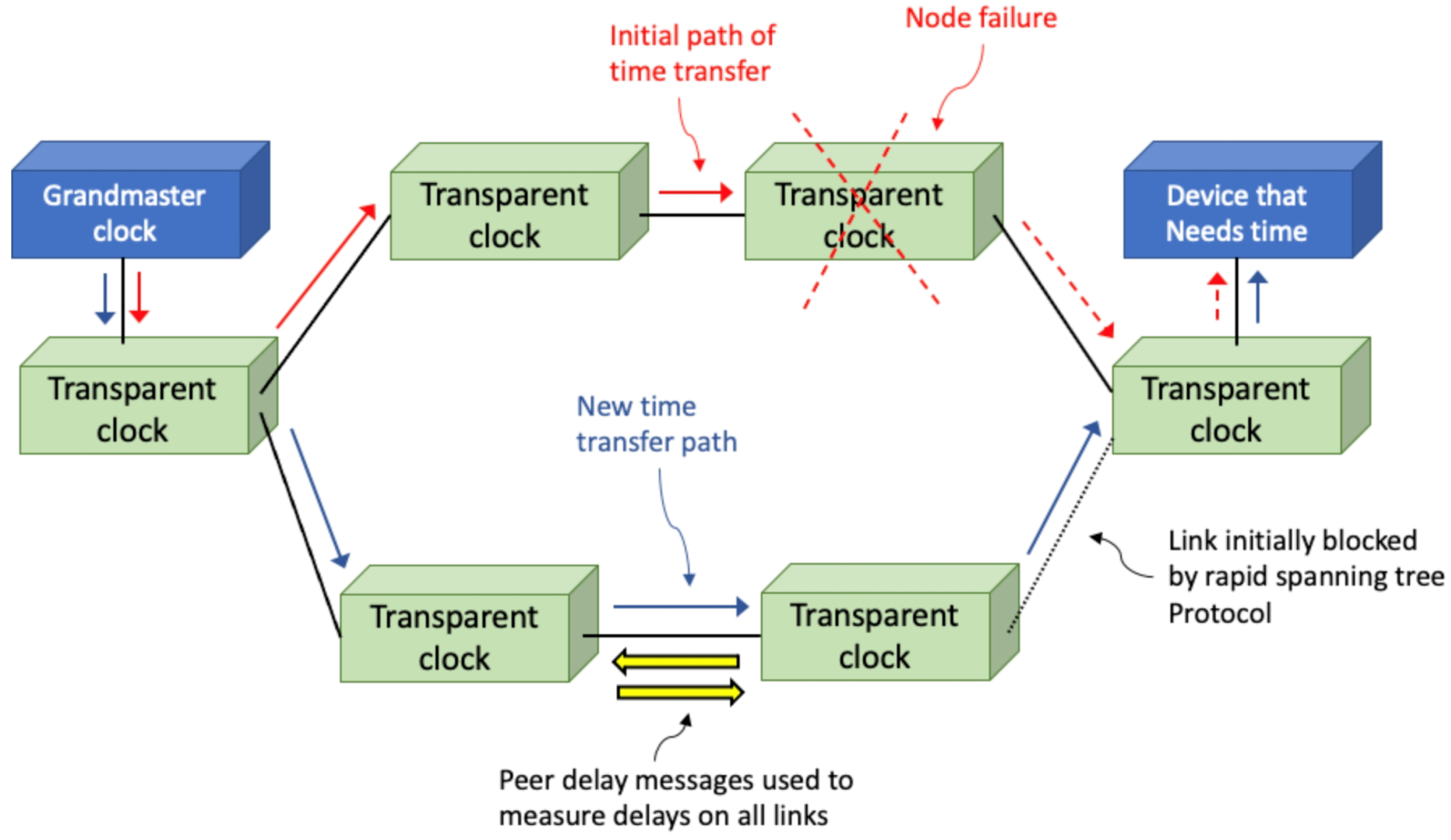
The Power Utility Profile uses a PTP option called
peer delay. Peer delay only works when all switches in the network support the PTP, but this is already a requirement owing to the timing performance demands. The idea is that all nodes on the networks exchange peer delay messages with neighboring devices to determine the delay through the cable and other hardware between adjacent nodes. This is done periodically in the background so that all link delays are known, even in a link blocked by the spanning tree protocol. This way, if there is a PTP sync message path change caused by a network rearrangement, then all of the link delays are already known, and the error in the sync message time caused by the delay can be immediately accounted for. This is important when equipment in a substation does not have a high-end oscillator to hold accurate time during a network reconfiguration.
Figure 4 shows such a reconfiguration when a switch fails.
IEEE Standard C.37.238-2017 was published in 2017. This standard is referred to as the Power Profile, and it is the Power Utility Profile with a few added enhancements. All PTP messages contain a domain number to allow more than one PTP logical network to operate on the same physical network. Each PTP port is configured to operate in a particular PTP domain indicated by its domain number. The domain number can be anything from 0 to 127, except the Power Profile can operate in domain 254. This ensures the isolation of the Power Profile from any other PTP Profile running on the network. The Power Profile also defines two message extensions to be distributed with the announce messages sent by the Grandmaster. One mandatory message extension includes a Grandmaster identity number and information about timing accuracy. The latter is described in
Section 4.3. The second message extension is optional and includes information about an alternate time scale. This is typically used to distribute time from a local time zone instead of UTC time.
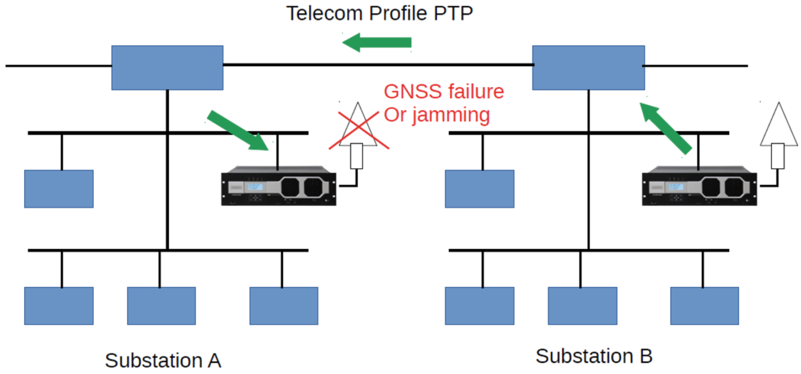
One more PTP Profile, the G.8275.2 standard, is used by some grid operators, and it is sometimes called the
Telecom Profile. This profile is defined by the ITU to support the time synchronization of radio heads for 4G and 5G wireless communications. It is useful for power grids because the profile does not need switches or routers to be PTP-capable.
Figure 5 shows how the Telecom Profile can be used to back up a timeserver in a substation that is experiencing GNSS availability issues.
GNSS jamming issues are usually localized, so it is likely that another base station would be unaffected. This backup method can be deployed even when time in the substation is distributed using the NTP or IRIG-B.
4.3. Accuracy
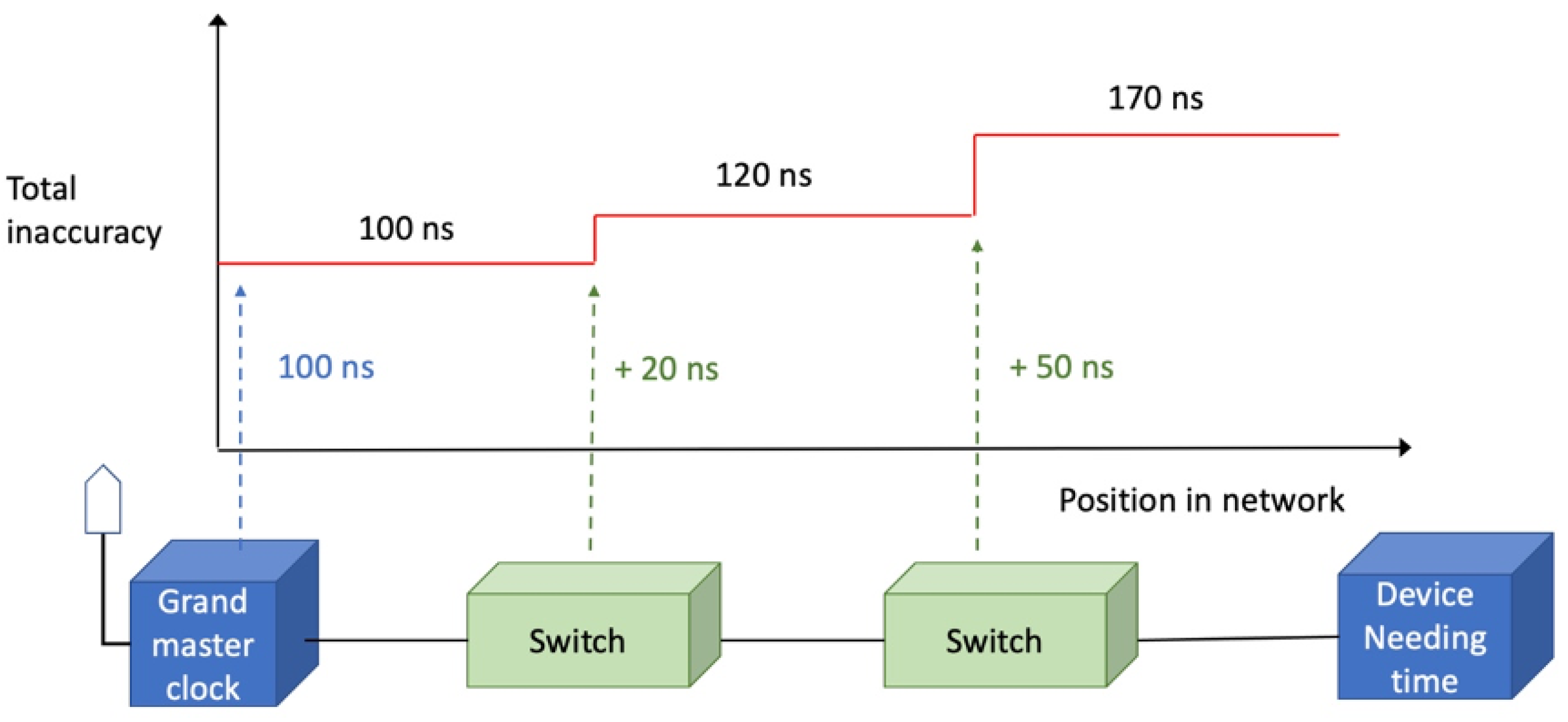
One challenge with network timing is the difficulty in determining whether devices in the grid are receiving time with the needed accuracy, which is a key requirement for obtaining proper measurements of the phase angle. This can be addressed by adding a message extension to a PTP message to accumulate the worst-case inaccuracy values as the message travels through the network. Fortunately, IEEE 1588 defines a means to extend PTP messages. These message extensions are called TLVs, after the fields in the extension for
type,
length, and
value. The type is a number that informs devices which TLV it is; the length is the number of octets in the TLV; the value is information provided by the TLV. To obtain the accumulated time inaccuracy for PTP-capable devices on the network, a TLV can be appended to the announce message sent by the Grandmaster clock. As the message traverses through switches and/or routers in the network, each switch or router adds its own error contribution. When the announce message arrives at a PMU, merging unit, or whichever device is receiving time, the device can check the accumulated inaccuracy number and verify that it is receiving time with sufficient accuracy or raise an alarm in the management interface if it is not. This concept for accumulating error information is depicted in
Figure 6.
IEEE C37.238-2017 defined the IEEE_C37_238 TLV for the PTP, which includes a total time inaccuracy field for the aforementioned purpose. IEEE Standard 1588-2019 defined the ENHANCED_ACCURACY_METRICS TLV, which reports more detail on the accumulated inaccuracy. The structure is shown in
Table 1.
The ENHANCED_ACCURACY_METRICS TLV tracks the number of PTP boundary clocks and transparent clocks—two kinds of PTP capable switches or routers—that contribute to the total inaccuracy numbers. The Grandmaster contributions to the total inaccuracy are separated from the contributions caused by the switches and routers through which the messages pass. This separation can be useful for applications that care more about relative time agreement in a network than they do about accuracy to an international time standard. The inaccuracy is also divided into static, dynamic, and transient categories. This can be important if, for example, a device only cares about the static time error. Perhaps, the device has algorithms to detect and ignore any transient time error, as well as a filter to remove dynamic error.
IEEE C37.238-2017 requires Grandmaster clocks to append all announce messages with the IEEE_C37 TLV and place their worst-case inaccuracy value in the total time inaccuracy field. However, it is optional for switches to update this field. IEEE 1588-2019 makes the ENHANCED_ACCURACY_METRICS TLV optional for all PTP nodes, including the Grandmaster clock. Neither standard mandates timing slaves to use received inaccuracy information. Thus, grid operators who want to use one of these inaccuracy TLVs must ensure that all of their PTP devices support the option.
4.4. Accommodating Nonhomogeneous Networks
The first edition of the IEEE C37.238 standard assumed that the transport medium would be Ethernet. However, when IEC 61850-9-3 was released in 2016, it included rules for PTP operation over the High-availability Seamless Redundancy (HSR) protocol and the Parallel Redundancy Protocol (PRP). The HSR and the PRP are defined in IEC 62439-3:2016 [
25] and use the connection hardware designed for Ethernet, as well as the same cables, connectors, and Physical layer (PHY) chips. However, at the data link layers, two copies of each frame are transmitted so that if one frame is lost en route owing to a failed switch or another problem, then the other frame can still be received, thus improving the reliability of communications. In HSRs, networks are formed in rings, and message are transmitted in both directions around the ring. The PRP or standard Ethernet devices can be attached to an HSR ring through a redundancy box (RedBox). In PRPs, duplicate frames traverse two parallel networks to double attached nodes. Standard Ethernet devices can also be attached to one of the PRP networks or converted to the PRP using a RedBox. If a device is connected to one of the parallel networks, then it is referred to as a
singly attached node.
Figure 7 shows how a substation network can use a mixture of Ethernet, the HSR, and the PRP.
The 2017 edition of the IEEE C37.238 standard also allows combinations or Ethernet, the HSR, and the PRP, referring to the IEC standards for details. Unlike ordinary data messages in PRP, PTP messages are not duplicated. One of the parallel paths is used to transfer time, and the other acts as a backup. In PRP, the first message to reach the destination is normally passed up the network stack, and the duplicate is dropped. However, with timing messages, increased dynamic time error could result if the PTP sync messages sometimes arrived from Network A and sometimes from Network B.
Some power grid operators also want to include wireless connections in their network, such as WiFi, and they might even need to transfer time over one of these WiFi links. Until recently, the PTP over WiFi was notoriously inaccurate because it was difficult to timestamp PTP messages at the hardware level because WiFi media access controls and PHYs are integrated in one chip that does not have the ability to create a PTP timestamp. However, IEEE 1588-2019 defines a mechanism for accurate time transfer in WiFi. Some transport technologies, such as WiFi and Ethernet passive optical networks, have built-in timing mechanisms. By
built-in, we mean that the timing mechanisms are specified in the WiFi standard itself (802.11) and not 1588. For WiFi, these mechanisms might be used to allow a battery-powered device to wake up just in time to receive a message from a controller. This scenario might not be needed in power grids because they already have sufficient power. However, the built-in timing mechanism can be used to allow PTP to tunnel time through a WiFi link by using a special PTP port. A special port is an interface between the PTP and some transport technology that has a built-in timing mechanism. This is shown in
Figure 8.
In IEEE 1588-2019, this interface is referred to as the Media-Dependent-Media- Independent (MDMI) interface. The MDMI does this through defined data structures needed to transfer time from a PTP sync message to the media-dependent timing mechanism and from that mechanism to create a PTP sync message. The implementation of the MDMI is different for each transport medium that has a built-in timing mechanism.
5. Potential for Precise Time Synchronization in a Grid Control Landscape
Precise time synchronization is already leveraged by wide-area power system measurements from PMUs and digital fault recording devices. Most existing deployments use forms of GNSS (e.g., GPS) to provide their precise timing. Concerns over the security and reliability of satellite-based clock sources have led to many critical applications leveraging a local time source as well, using security practices and sample profiles from standards or application profiles. Examples of such standards or profiles include IEEE 1588-2019 [
11], IEEE C37.237-2018 [
26], and IEEE/IEC 61850-9-3:2016 [
27] or C37.238-2017 [
28].
Regardless of the source of the precise time information, it enables two primary aspects in power system operations. The first is enabling the synchronization of geographically diverse measurements, thereby providing a large area view of the system within a common context (and a common reference frame for phase measurements across the region). The second is enabling timing-based data, control, and information security capabilities to help detect erroneous or malicious information. This section outlines some examples of these two capabilities, as well as how precision timing information is being used or can be used to improve power grid controls and operations.
5.1. Improved Situational Awareness
Precise time synchronization has enabled geographically dispersed measurements to be accurately timestamped to a common reference. With this information, wide area information can be combined and aggregated to accurately represent the state of the power system without needing to precisely account for variable communication and reporting delays. This wide area information enables a greater situational awareness of the interconnected system as a whole and also enables new approaches for analysis.
As mentioned previously, many instrumentation standards define their acceptable error around phase angle differences from the true value. In the power system, precise timestamps allow the phase angles from two sites that are a significant distance apart to be directly compared. Phase angle differences between buses on the power system can represent the amount of power flowing between two buses or areas of the system. Power system operators use this information to verify power transfers across interconnections and to monitor overall indications of grid health and stress. State estimators use phase and other information to provide insights into portions of the power system without direct measurements and to detect conditions that diverge from the modeled assumptions. This improves the overall situational awareness and can allow corrective actions before a large-scale outage occurs.
Precise and accurate time-synchronized measurements also allow large-scale behaviors on the power system to be examined. Interarea oscillations can be a significant problem in power systems, and many have their behavior based on interactions between generators or areas separated by significant distance. In the western United States and Canada, generators in the northern part of the interconnected power system (British Columbia and Alberta) interact with generators in the southern part of the system (California and Arizona) to produce a low frequency oscillation across the system [
29]. Under adverse conditions, this oscillation can actually become unstable and eventually cause large-scale outages and/or blackouts, as was witnessed in August 1996 [
30]. Without accurate and precise timing information, combining measurements from British Columbia and Arizona would be very difficult, and this wide-area situational awareness would be impossible.
5.2. Improved Resilience
Improved situational awareness, especially wide-area situational awareness, allows for more efficient and more responsive operations on the power grid. In contingency situations, having an accurate account of the overall state of the power system can allow actions to be taken to mitigate the outage area or coordinate service restoration after an outage. The result is an improved resilience to overall grid operations, particularly in the context of being able to address unforeseen events or new contingencies in the system.
The two examples provided for improved situational awareness and improved resilience are larger scale behaviors on the power system that benefit from precise timing information. However, smaller scale and local controls can also benefit from the timing information to improve resilience. Many protective device vendors leverage the precise timing of local and distant measurements to quickly switch lines out of service, thereby preventing a larger scale outage and allowing the power system to continue operating. Under the right deployments, this can include detecting and isolating falling conductors before they reach the ground [
31], which can prevent larger scale electrical disturbance and secondary impacts, such as wildfires, that would affect larger infrastructure.
Beyond situational awareness-related improvements to operations and resilience, precise timing information also improves system resilience. With precise and accurate timing information against a common reference, simple time-based validity methods can be deployed, such as ignoring data or controls with significant delays. Such timing information can also be used to monitor the overall communication infrastructure of power systems, providing a means to detect problems in the communication system caused by congestion or bandwidth issues, equipment failure, and—potentially—malicious interference. Recognizing or diagnosing compromised information, either naturally occurring or deliberately caused, allows either the system to be repaired or suspect information to be further evaluated, helping ensure resilient operation of the power system.
5.3. New Opportunities Provided by Increased Time Fidelity
Increased time fidelity primarily enables the coordination of faster behaviors on the power system. Point-on-wave measurements are becoming more widely deployed on the power system, providing insights into smaller time scale dynamics, such as those associated with inverter-based generation sources (e.g., photovoltaic) [
32,
33,
34]. Accurately reconstructing behaviors captured by these devices, especially over larger geographic distances, requires greater precision and accuracy in the timing information. Some behaviors, particularly those associated with inverters, occur in the nanosecond to microsecond range. The coordination of measurements and information associated with those events, especially on a larger geographic scale, is necessary to detect and understand these behaviors to help mitigate them or recognize their overall system impacts [
35].
5.4. Risks
From a power system perspective, risks in increased precision and/or accuracy in timing information are mostly related to applications of any associated data. Increased precision can enable faster measurement rates, which could result in handling larger data volumes. It will also require more stringent requirements on hardware devices, such as the instrumentation transformer requirements described in
Section 3.1. If information must be coordinated over larger areas in more precise timestamps, then communication requirements and source clock requirements will also become more restrictive. All of these challenges can be surmounted with current technology. The largest risk to power system operations is ensuring that appropriate standards and certifications are leveraged to maintain the integrity of information based on these more precise timing values.
6. Conclusions
This paper described distributed clock protocols in detail and provided insight into how they can be employed in various ways to benefit the power grid. The availability of IEEE 1588-2019 is a recent and significant advancement in this topic area, and the authors presented several examples that illustrate how this new technology impacts the grid and why its potential is exciting. This paper provided context, including the requirements for timing uncertainty, and described how the new PTP timing protocol advances address multiple issues. By illustrating timing needs with examples taken from the power grid, this paper covered a range of such issues—including discontinuities (e.g., leap seconds), uptime, and the properties of the time uncertainty; how the timing signal is propagated (e.g., WiFi, fiber, existing power lines); whether the solution is interoperable and backward compatible with legacy systems; security of the timing signal (e.g., spoof-proof, jamming resistant, provisions for authentication verification); latency effects in sensor measurements and timely actuations in grid controls to evade failures or disasters; and cost factors, both one-time costs at installation and recurring costs throughout the solution’s lifetime. Finally, this paper showed applications of these advances by identifying how the power grid gains new capabilities for improved situational awareness, improved resilience, and improved time fidelity.
The topic of distributed clock protocols and their potential within power grid control is fertile ground for future work. IEEE 1588-2019 is actively working to address several new capabilities, including enhanced cybersecurity measures, enhancements for optical transport networks, and improvements aimed at latency and/or asymmetry calibration. More broadly, there is much interest in GNSS alternatives for time distribution, implementation details on precise time distribution over long distances, and a national time service.
The paper serves as a resource in clarifying the importance of precision time synchronization and its role in supporting and advancing the development of future smart grids for which the public and industry are expected to have increased requirements for the on-demand flexibility, reliability, and resilience of power grids.


