Abstract
Considering the problems of the low energy recovery efficiency and the short driving range of pure electric vehicles, a new electromechanical–hydraulic coupled power electric vehicle is proposed. First, we develop an electromechanical–hydraulic coupled power electric vehicle model and design an energy management strategy to match it. On this basis, an optimization strategy is proposed with the goal of improving the braking energy recovery efficiency and avoiding the impact of high-speed braking energy recovery on the hydraulic system. The energy recovery mode conversion is optimized for different vehicle speeds when braking. Finally, the proposed optimization strategy is verified by joint simulation. The results show that when the vehicle speed is higher than 10 m/s for energy recovery mode switching, the total recovery efficiency of the whole vehicle increases to 97.273% and the SOC of the power battery increases by 0.14%. This provides strong support for improving the driving range of electromechanical–hydraulic coupled power electric vehicles.
1. Introduction
With the significant increase in the use of vehicles, the application of renewable resources has become one of the most critical developments in the modern automotive industry [1]. At present, energy and environmental problems are becoming increasingly serious, and manufacturers are coming under unprecedented pressure from public opinion [2]. On the economic side, the market is increasingly receptive to and accepting of vehicles based on new forms of energy, which are bound to become the mainstay of future vehicle sales. Society is also keen to see vehicles based on new forms of energy in order to protect the environment and reduce energy consumption. Automakers are experiencing a disruptive digital revolution in manufacturing and commercial operations with the creation of vehicles based on new forms of energy [3]. Governments strongly support the development of vehicles based on new forms of energy, which are currently divided into electric vehicles (EVs), hybrid electric vehicles (PHEVs), and fuel cell electric vehicles (FCEVs) [4,5]. Vehicles based on new forms of energy will undoubtedly become the key to the future development of and competition in the world’s automotive industry [6]. In the past decade, EVs have received much attention due to their high energy efficiency, zero emissions, and low level of noise [7,8]. PHEVs usually use a small internal combustion engine powered by fossil fuels with an electric motor, which can increase the range of the vehicle but not eliminate the use of fossil fuels [9]. In terms of average values, the appropriate value for the combustion engine is 1.54 (J/(kg·m)) [10]. FCEVs are considered to be one of the cleanest vehicles that do not use fossil fuels, but they are limited by the hydrogen infrastructure and the procurement cost of fuel cells, which will have a low penetration rate in the coming years [11].
1.1. Literature Review
Although battery technology has advanced considerably, existing batteries do not meet consumers’ demands regarding the electrical energy consumption of EVs [12]. Constrained by battery technology and other issues, EVs have a low cruising efficiency, are short range, and have a short battery life in urban conditions [13]. The energy-saving potential of EVs depends on the cooperation of energy storage components and power batteries [14]. Wang et al. established a battery–flywheel composite energy storage system; the overall recovered energy increased by 1.17 times and the maximum charging current of the battery decreased by 42.27% compared with a single battery system [15]. Pipitone et al. used supercapacitors as energy storage devices connected to brushless motors through appropriately designed power converters, with energy savings of about 20% [16]. Wu et al. proposed a hydraulic hybrid propulsion system for heavy-duty vehicles that is suitable for the working frequency of stop-and-go heavy vehicles [17].
EVs are a typical complex energy system [18]. During driving, complex energy, power, information conversion, fitting, etc., will occur. The performance of the vehicle is closely related to the control strategy used [9]. The use of an optimal control strategy can reasonably allocate energy and help to achieve a lower energy consumption [19,20,21]. The design of this ideal strategy depends on the route selected, the degree of congestion, the global positioning system (GPS), etc. [22]. Common control strategies can be divided into rule-based control strategies and optimization-based control strategies [23,24]. Rule-based control strategies are often formulated through experience or fuzzy logic-based control strategies and are widely used due to their simplicity and practicality [25,26]. Zeng et al. proposed an energy management strategy based on the predictive control of road slope using a stochastic model; the proposed method helps keep the battery state of charge (SOC) within the appropriate boundaries [27,28,29]. Sun proposed a dual-mode energy management strategy combining the closed-loop control of regenerative current and the closed-loop control of regenerative torque in order to achieve a higher regeneration efficiency within the dynamic limits of the battery charging current [30]. Qiu et al. proposed the use of a novel regenerative braking control strategy for the EV anti-lock braking process [31]. Wang et al. regulated the regenerative braking torque using charging voltage variation; the use of their energy management strategy can accurately realize regenerative braking behavior [32].
1.2. Challenges of Energy Management Strategies
The energy consumption of EVs during the braking process is approximately 30–50% of the total energy used [33]. Energy recovery is a crucial technology for improving the driving range of electric vehicles. The traditional energy management strategy used involves a wide range of aspects. The braking energy recovery components only perform energy recovery based on the targets entered in the braking energy management strategy, without considering the impact of the vehicle speed on the braking energy components. If the vehicle speed is too high or too low, the braking energy recovery components will be considered to impact or affect the braking energy recovery efficiency of the entire vehicle.
1.3. Paper Contribution
- (1)
- A new type of electro-mechanical-hydraulic coupled power vehicle (EMH-EV), which can couple electrical energy, mechanical energy, and hydraulic energy, is proposed.
- (2)
- A braking energy management strategy that matches the EMH-EV is formulated.
- (3)
- The braking energy management strategy is optimized based on the vehicle speed threshold to improve the braking energy recovery efficiency of the EMH-EV and avoid the impact of high-speed braking energy recovery on the hydraulic system.
- (4)
- The feasibility of the optimized energy management strategy is verified by a simulation.
1.4. The Structure of the Paper
2. Vehicle Model Design
A hybrid vehicle is a vehicle drive system composed of two or more single drive systems that can operate simultaneously. The driving power of the vehicle is provided separately or jointly by a single drive system according to the actual vehicle driving state. Unlike hybrid vehicles, the only power source in the EMH-EV is the power battery, and hydraulic power is only used as auxiliary power. The electromechanical hydraulic coupler (EMH-C) in the EMH-EV is an entirely independent mechanical module that converts energy and power. Mechanical energy, electric energy, and hydraulic energy can be converted into each other through the EMH-C. Thus, the model was called the EMH-EV.
The power system structure of the EMH-EV is shown in Figure 1. The EMH-EV is composed of the EMH-C, clutch, main reducer, vehicle control unit (ECU), low-pressure accumulator (LPA), high-pressure accumulator (HPA), power battery, hydraulic control unit (HCU), wheels, and other components. The EMH-C is the core component of the EMH-EV.
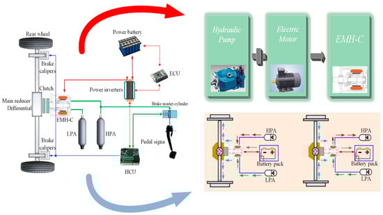
Figure 1.
The structure of the EMH-EV.
Since the EMH-EV is a new EV-based vehicle, the electric power contained in the power battery is the only power source for the vehicle, and the hydraulic energy is recovered from the braking energy or stored in the high-/low-pressure accumulator after converting the electric energy through the EMH-C [34]. When the vehicle is started at a low speed or with a heavy load, the vehicle is driven independently by hydraulic power or auxiliary electric power to provide more torque to ensure the regular operation of the vehicle. At this time, hydraulic oil flows from the HPA to the LPA through the EMH-C to produce hydraulic power to run the vehicle. When the vehicle is running normally, it is fully powered by electric power. When the vehicle is braking at low and medium speeds, the vehicle performs hydraulic-energy recovery braking, the hydraulic braking force provides all the braking force, and the hydraulic oil flows from the LPA to the HPA to store the hydraulic energy in the high-pressure accumulator. When the vehicle is braking at a high speed, the electric energy is recovered and the electric braking force provides the braking power. The emergency braking of the vehicle stops all regenerative braking energy recovery and the vehicle is provided with full braking force by mechanical braking force.
The EMH-C is a critical component of the EMH-EV that combines the structure of a swashplate axial piston pump/motor with a permanent magnet synchronous motor structure, as shown in Figure 1. It can realize the single-to-single energy conversion of mechanical energy, hydraulic energy, and electric energy and meet the multi-to-single and single-to-many energy conversion requirements. It has a high practicability. Furthermore, the EMH-C has a compact structure and a high working efficiency. The parameters of the vehicle and its components are shown in Table 1.

Table 1.
Vehicle parameters.
3. Mathematical Modeling
3.1. Vehicle Longitudinal Dynamics Model
The vehicle will be subject to various resistances in driving; first, the kinematic equations of the whole vehicle are established:
where Ff is the rolling resistance of the vehicle (N), Fw is the air resistance to which the vehicle is subjected (N), Fj is the acceleration resistance (N), M is the mass of the vehicle (kg), G is the gravity of the vehicle, f is the rolling resistance coefficient, CD is the air resistance coefficient, A is the windward area (m2), u is the vehicle travel speed (m/s), is the vehicle travel acceleration (m/s2), δ is the vehicle rotating mass conversion factor, ρ is the air density (kg/m3), and g is the acceleration due to gravity.
3.2. Electrodynamic Modeling
The EMH-EV is a model based on the EV. Electric power is the main power used in the EMH-EV, so the modeling of electric power is critical. The electric power Pe is:
where Te is the torque (Nm), n is the speed (r/min), and ηe is the efficiency of the electric power.
3.3. Hydraulic Dynamic Modeling
Hydraulic power is the key power of the EMH-EV. The hydraulic power Ph is:
where umaxa is the maximum speed under hydraulic drive (m/s), ηh is the mechanical transmission efficiency of the hydraulic system to the wheels, G = m0 × g, m0 is the fully loaded mass (kg), Tp is the torque of the hydraulic power module (Nm), ∆p is the differential pressure between the inlet and outlet of the hydraulic module (MPa), Vp is the displacement, np is the speed of the hydraulic module (m3/rev), and ηp is the mechanical efficiency.
3.4. Power Battery Model
The power battery of the EMH-EV is the only power source and has a significant impact on driving. The output voltage of the power battery Uout is:
where Uoc is the open-circuit voltage of the power cell (V), R is the internal resistance of the power cell (Ω), I is the power cell current, SOC is the charge state of the power cell (%), SOC0 is the initial charge state of the power cell (%), and Q0 is the total battery capacity of the power cell (mAh).
3.5. Hydraulic Accumulator Model
The high-pressure accumulator and low-pressure accumulator in the process of impulse discharge are determined according to Boyle’s law:
where P0 is the filling pressure of the accumulator (MPa), V0 is the volume of gas at a pressure of P0 in the accumulator (m3), P1 is the minimum working pressure of the accumulator (MPa), V1 is the volume of gas at a pressure of P1 in the accumulator (m3), P2 is the maximum working pressure of the accumulator (MPa), and V2 is the volume of gas at a pressure of P2 in the accumulator (m3).
4. Strategy Design
It is essential to propose a reasonable braking energy management strategy to recover the braking energy into the hydraulic accumulator or power battery as efficiently as possible.
Economic Commission of Europe (ECE) regulations stipulate that the braking force distribution of a vehicle should meet the directional stability requirements of the vehicle when braking, as shown in Figure 2. Because of the increase in regenerative braking force, the design of the energy management strategy should consider the braking force in medium-intensity braking mode and emergency braking mode, as shown in Figure 3. Y represents yes, N represents no, z is the braking intensity signal, PHPA represents the pressure accumulator pressure value letter, and SOC represents the power battery power signal. Because the discharge depth of passenger cars is 10–90%, the SOC signal in the control strategy logic diagram is the power percentage in the discharge depth range. When the EMH-EV starts braking, the sensor detects the brake pedal signal, the vehicle starts to judge the braking intention of the driver while determining the brake pedal opening (z), and then the vehicle starts to act according to the braking energy management strategy shown in Figure 3.
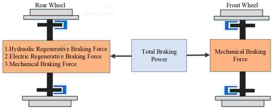
Figure 2.
Brake force distribution.
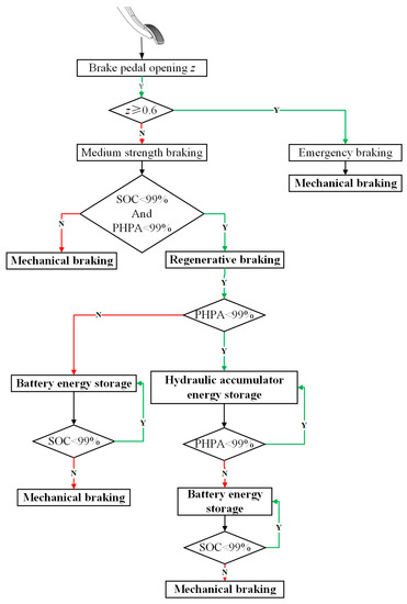
Figure 3.
Brake energy management strategy.
- When the brake pedal opening is z < 0.6, the vehicle selects the medium-intensity braking mode; the power cell SOC signal and the hydraulic accumulator pressure value PHPA signal are detected by sensors [35].
- 1.
- If the value of SOC and PHPA is higher than 99%, in order to prevent the battery SOC and high-pressure accumulator pressure value PHPA from overcharging and ensure the safety of the vehicle, the vehicle will not enter regenerative braking mode and will perform mechanical braking.
- 2.
- If the SOC and PHPA are lower than 99%, the vehicle performs regenerative braking. Considering the high efficiency of hydraulic energy recovery, the vehicle first detects whether the PHPA is greater than 99%. When PHPA < 99%, hydraulic energy recovery is carried out until PHPA = 99%. Then, hydraulic energy recovery ends and the system carries out electric energy recovery. When SOC = 99%, the EMH-EV performs mechanical braking.
- When the brake pedal opening z ≥ 0.6, to ensure the safety of the EMH-EV emergency braking, no more braking energy recovery will be performed, and the vehicle will directly enter a state of mechanical braking.
5. Optimization Strategy
To further improve the energy recovery efficiency of the EMH-EV and the impact of high speeds on the hydraulic energy system, an optimization strategy for EMH-EV braking energy management is established based on the vehicle speed threshold to maximize the economy of the whole vehicle and the protection of the hydraulic energy system while satisfying the premise of power and braking stability. The goals of the economy are to reduce the energy consumption of the power cell and improve the recovery efficiency of the hydraulic energy accumulator. The goal of hydraulic system protection is to reduce the impact of high-speed braking on the hydraulic system. In this paper, AMESim/Simulink simulation is used to determine the optimal speed threshold for the regenerative braking of the EMH-EV using either electrical-energy regenerative braking or hydraulic-energy regenerative braking.
The results of the EMH-EV are shown in Figure 4 and Figure 5 after operating with different speed thresholds selected by the EMH-EV under the NEDC conditions. The highest electric-energy recovery efficiency of the EMH-EV is shown in Figure 4a, where the vehicle speed is 8 m/s and the recovery efficiency reaches 94.934%; Figure 4b demonstrates that the highest hydraulic-energy recovery efficiency of the EMH-EV is 99.935% at 10 m/s. The total recovery efficiency of the EMH-EV based on the electric-energy recovery efficiency and the hydraulic-energy recovery efficiency is shown in Figure 5, and the total recovery efficiency reaches 97.273% at 10 m/s. When the vehicle brakes and the vehicle speed is 10 m/s, the vehicle switches from hydraulic-energy recovery to electric-energy recovery under the premise of ensuring the rule energy management strategy, avoiding the impact of the braking energy recovery process on the hydraulic system at high speed and, at the same time, reducing the energy consumption of the whole vehicle and effectively extending the driving distance of the EMH-EV. The optimized control strategy for the energy recovery mode is shown in Figure 6, where v denotes the speed.
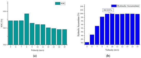
Figure 4.
Recovery efficiency at different velocities: (a) comparison of the recovery efficiency of electric energy; (b) comparison of the efficiency of hydraulic energy recovery.
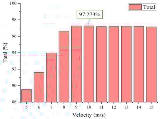
Figure 5.
Total recovery efficiency at different velocities.
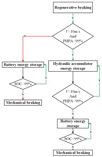
Figure 6.
Optimized energy recovery control strategy.
The NEDC condition includes four urban circulation conditions and one suburban condition. The EMH-EV can fit the NEDC vehicle speed curve well, as shown in Figure 7, meaning that it meets the requirements of the NEDC condition. This proves the feasibility of the strategy after vehicle speed threshold optimization.
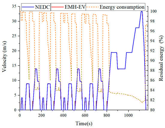
Figure 7.
NEDC results.
From the torque distribution in the EMH-C, as shown in Figure 8, it is evident that the EMH-EV is able to operate according to the optimized control strategy when the vehicle brakes and the vehicle performs electrical-energy recovery braking when the vehicle speed exceeds 10 m/s. When the vehicle speed is lower than 10 m/s, the vehicle is limited to hydraulic-energy recovery braking. The hydraulic accumulator pressure reaches the requirement to continue and carry out electrical-energy recovery braking, ensuring the stability of the optimized control strategy after matching with the EMH-EV.
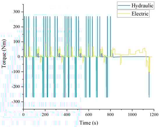
Figure 8.
Torque distribution of the EMH-C.
Because the EMH-EV is a new model built based on the EV, the value of the SOC is the essential reference value used to measure the feasibility of the optimized strategy. The optimized energy strategy after running the NEDC conditions, as shown in Figure 9, improves the SOC by 0.14% compared with the original energy management and verifies the advantages of the optimized energy management strategy.
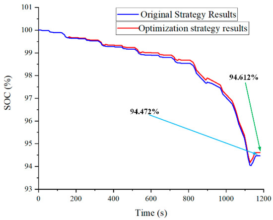
Figure 9.
SOC comparison.
6. Conclusions
In this paper, a new electromechanical-hydraulic coupled power vehicle is proposed. Its longitudinal dynamics and electrodynamic, hydraulic power, battery, and hydraulic accumulator parts are mathematically modeled separately. An energy management strategy is designed to match the performance of the electromechanical–hydraulic coupled power electric vehicle. The medium strength braking mode and emergency braking mode are distinguished according to the brake pedal opening. In medium-strength braking mode, when SOC < 99% and PHPA < 99%, the vehicle uses regenerative-braking energy recovery. Hydraulic accumulator energy storage is prioritized until the pressure reaches the threshold value, then the vehicle switches to power battery storage. When both reach the threshold value, the vehicle switches to mechanical braking mode. To improve the energy recovery efficiency after the operation of the rule energy management strategy, the simulation of different vehicle speed thresholds determines 10 m/s as the threshold for switching to energy recovery mode during regenerative braking. When braking the vehicle below 10 m/s, priority is given to hydraulic-energy recovery braking; above 10 m/s, energy recovery by electric-energy recovery braking is prioritized. After optimizing the energy management strategy, the recovery efficiency of the whole vehicle reaches 97.273%. The feasibility of this strategy was verified by simulating the NEDC operating conditions. The simulation results show that the electromechanical–hydraulic coupled power electric vehicle can work according to the optimized energy management strategy. The power battery SOC is improved by 0.14% compared with the original control strategy.
This study solves the problems of the low recovery efficiency and short driving range of electric vehicles. It provides an essential foundation for further research on the electromechanical–hydraulic coupled power electric vehicle.
Author Contributions
Conceptualization, J.Y.; Data curation, Z.M.; Formal analysis, J.Y.; Methodology, T.Z., H.Z. and Z.M.; Resources, J.Y., T.Z. and H.Z.; visualization, Q.Z. Writing original draft, Z.M.; Writing review & editing, Z.M. and T.Z. All authors have read and agreed to the published version of the manuscript.
Funding
This research was funded by the National Natural Science Foundation of China, grant number 52075278, and Municipal Livelihood Science and Technology Project of Qingdao, grant number 19-6-1-92-nsh.
Institutional Review Board Statement
Not applicable.
Informed Consent Statement
Not applicable.
Conflicts of Interest
The authors declare no conflict of interest.
References
- Rezk, H.; Nassef, A.M.; Abdelkareem, M.A.; Alami, A.H.; Fathy, A. Comparison among various energy management strategies for reducing hydrogen consumption in a hybrid fuel cell/supercapacito/battery system. Int. J. Hydrogen Energy 2019, 46, 6110–6126. [Google Scholar] [CrossRef]
- Hong, J.; Wang, Z.; Chen, W.; Wang, L.; Lin, P.; Qu, C. Online Accurate State of Health Estimation for Battery Systems on Real-World Electric Vehicles with Variable Driving Conditions Considered. J. Clean. Prod. 2021, 294. [Google Scholar] [CrossRef]
- Li, K. Research on digital strategy of new energy vehicle manufacturing enterprises’ service transformation. Energy China 2020, 42, 25–30. [Google Scholar]
- Chen, L.; Chen, Z.X.; Xu, X.; Wang, F.; Cai, Y.F.; Zhang, T. Energy management strategy of plug-in hybrid electric vehicle with engine start and stop optimization. Automot. Eng. 2021, 43, 313–322. [Google Scholar]
- Hong, J.C.; Wang, Z.P.; Zhang, T.Z.; Yin, H.; Zhang, H.; Huo, W.; Zhang, Y.; Li, Y. Research on integration simulation and balance control of a novel load isolated pure electric driving system. Energy 2019, 189. [Google Scholar] [CrossRef]
- Hong, J.C.; Wang, Z.P.; Yao, Y.T. Fault prognosis of battery system based on accurate voltage abnormity prognosis using long short-term memory neural networks. Appl. Energy 2019, 251. [Google Scholar] [CrossRef]
- Nikoobakht, A.; Aghaei, J.; Khatami, R.; Mahboubi-Moghaddam, E.; Parvania, M. Stochastic flexible transmission operation for coordinated integration of plug-in electric vehicles and renewable energy sources. Appl. Energy 2019, 238, 225–238. [Google Scholar] [CrossRef]
- Yang, J.W.; Yang, H.; Zhang, X.L.; He, Z.Y. A charging optimization strategy on charging and swapping station for electric buses based on optimization of switching rules and matching of buses and batteries. Proc. CSEE 2019, 39, 2337–2347. [Google Scholar]
- Zhang, P.; Yan, F.W.; Du, C.Q. A comprehensive analysis of energy management strategies for hybrid electric vehicles based on bibliometrics. Renew. Sustain. Energy Rev. 2015, 48, 88–104. [Google Scholar] [CrossRef]
- Mamala, J.; Mieja, M.; Pranowski, K. Analysis of the total unit energy consumption of a car with a hybrid drive system in real operating conditions. Energies 2021, 14, 3966. [Google Scholar] [CrossRef]
- Ahmadi, P.; Torabi, S.H.; Afsaneh, H.; Sadegheih, Y.; Ganjehsarabi, H.; Ashjaee, M. The effects of driving patterns and PEM fuel cell degradation on the lifecycle assessment of hydrogen fuel cell vehicles. Int. J.Hydrogen Energy 2019, 45, 3595–3608. [Google Scholar] [CrossRef]
- Kouchachvili, L.; Yaici, W.; Entchev, E. Hybrid battery/supercapacitor energy storage system for the electric vehicles. J. Power 2018, 374, 237–248. [Google Scholar] [CrossRef]
- Bai, Y.; He, H.; Li, J.; Li, S.; Wang, Y.-X.; Yang, Q. Battery anti-aging control for a plug-in hybrid electric vehicle with a hierarchical optimization energy management strategy. J. Clean. Prod. 2019, 237, 117841. [Google Scholar] [CrossRef]
- Khaligh, A.; Li, Z.H. Battery, Ultracapacitor, fuel cell, and hybrid energy storage systems for electric, hybrid electric, fuel cell, and plug-in hybrid electric vehicles: State of the art. IEEE Trans. Veh. Technol. 2010, 59, 2806–2814. [Google Scholar] [CrossRef]
- Wang, W.; Li, Y.; Shi, M.; Song, Y.L. Optimization and control of battery-flywheel compound energy storage system during an electric vehicle braking. Energy 2021, 226. [Google Scholar] [CrossRef]
- Pipitone, E.; Vital, G. A regenerative braking system for internal combustion engine vehicles using supercapacitors as energy storage elements—Part 1: System analysis and modelling. J. Power Sources 2020, 448, 227368. [Google Scholar] [CrossRef]
- Wu, W.; Hu, J.B.; Yuan, S.H.; Di, C.F. A hydraulic hybrid propulsion method for automobiles with self-adaptive system. Energy 2016, 114, 683–692. [Google Scholar] [CrossRef]
- Tang, X.P.; Wang, Y.J.; Zou, C.F.; Yao, K.; Xia, Y.; Gao, F. A novel framework for Lithium-ion battery modeling considering uncertainties of temperature and aging. Energy Convers. Manag. 2019, 180, 162–170. [Google Scholar] [CrossRef]
- Zheng, C.; Li, W.; Liang, Q. An energy management strategy of hybrid energy storage systems for electric vehicle applications. IEEE Trans. Sustain. Energy 2018, 9, 1880–1888. [Google Scholar] [CrossRef]
- Malikopoulos, A.A. Supervisory power management control algorithms for hybrid electric vehicles: A survey. IEEE Trans. Intell. Transp. Syst. 2014, 15, 1869–1885. [Google Scholar] [CrossRef]
- Torres, J.L.; Gonzalez, R.; Gimenez, A.; Lopez, J. Energy management strategy for plug-in hybrid electric vehicles. A comparative study. Appl. Energy 2014, 113, 816–824. [Google Scholar] [CrossRef]
- Li, L.; Yang, C.; Zhang, Y.H.; Zhang, L.; Song, J. Correctional DP-based energy management strategy of plug-in hybrid electric bus for city-bus-route. IEEE Trans. Veh. Technol. 2015, 64, 2792–2803. [Google Scholar] [CrossRef]
- Martínez, C.M.; Hu, X.S.; Cao, D.P.; Velenis, E.; Gao, B.; Wellers, M. Energy management in plug-in hybrid electric vehicles: Recent progress and a connected vehicles perspective. IEEE Trans. Veh. Technol. 2017, 66, 4534–4549. [Google Scholar] [CrossRef] [Green Version]
- Zhang, Y.J.; Chu, L.; Fu, Z.C.; Xu, N.; Guo, C.; Zhang, X.; Chen, Z.; Wang, P. Optimal energy management strategy for parallel plug-in hybrid electric vehicle based on driving behavior analysis and real time traffic information prediction. Mechatronics 2017, 46, 177–192. [Google Scholar] [CrossRef]
- Xu, N.; Kong, Y.; Chu, L.; Ju, H.; Yang, Z.; Xu, Z.; Xu, Z. Towards a smarter energy management system for hybrid vehicles: A comprehensive review of control strategies. Appl. Sci. 2019, 9, 2026. [Google Scholar] [CrossRef] [Green Version]
- Sarvaiya, S.; Ganesh, S.; Xu, B. Comparative analysis of hybrid vehicle energy management strategies with optimisation of fuel economy and battery life. Energy 2021, 228, 120604. [Google Scholar] [CrossRef]
- Hong, J.C.; Wang, Z.P.; Chen, W.; Yao, Y. Synchronous multi-parameter prediction of battery systems on electric vehicles using long short-term memory networks. Appl. Energy 2019, 254. [Google Scholar] [CrossRef]
- Han, W.J.; Zou, C.F.; Zhou, C.; Zhang, L. Estimation of cell SOC evolution and system performance in module-based battery charge equalization systems. IEEE Trans. Smart Grid 2019, 10, 4717–4728. [Google Scholar] [CrossRef]
- Zeng, X.R.; Wang, J.M. A Parallel hybrid electric vehicle energy management strategy using stochastic model predictive control with road grade preview. IEEE Trans. Control Syst. Technol. 2015, 23, 2416–2423. [Google Scholar] [CrossRef]
- Sun, D.S.; Zhang, J.Z.; He, C.K.; Han, J.H. Dual-mode regenerative braking control strategy of electric vehicle based on active disturbance rejection control. Proc. Inst. Mech. Eng. Part D J. Automob. Eng. 2021, 235. [Google Scholar] [CrossRef]
- Qiu, C.Q.; Wang, G.L.; Meng, M.Y.; Shen, Y.J. A novel control strategy of regenerative braking system for electric vehicles under safety critical driving situations. Energy 2018, 149, 329–340. [Google Scholar] [CrossRef]
- Wang, J.C.; He, R.; Kim, Y.B. Optimal control of regenerative hydraulic composite braking system based on a voltage variable charging control scheme. Proc. Inst. Mech. Eng. Part D J. Automob. Eng. 2019, 234, 536–551. [Google Scholar] [CrossRef]
- Ji, F.Z.; Pan, Y.; Zhou, Y.; Du, F.; Zhang, Q.; Li, G. Energy recovery based on pedal situation for regenerative braking system of electric vehicle. Veh. Syst. Dyn. 2019, 58, 144–173. [Google Scholar] [CrossRef]
- Yang, J.; Zhang, T.Z.; Zhang, H.X.; Hong, J.; Meng, Z. Research on the starting acceleration characteristics of a new mechanical–electric–hydraulic power coupling electric vehicle. Energies 2020, 13, 6279. [Google Scholar] [CrossRef]
- Xin, Y.F.; Zhang, T.Z.; Zhang, H.X.; Zhao, Q.; Zheng, J.; Wang, C. Fuzzy logic optimization of composite brake control strategy for load-isolated electric bus. Math. Probl. Eng. 2019, 2019, 9735368. [Google Scholar] [CrossRef]
Publisher’s Note: MDPI stays neutral with regard to jurisdictional claims in published maps and institutional affiliations. |
© 2021 by the authors. Licensee MDPI, Basel, Switzerland. This article is an open access article distributed under the terms and conditions of the Creative Commons Attribution (CC BY) license (https://creativecommons.org/licenses/by/4.0/).