Article

Frequency Control of Large-Scale Interconnected Power Systems via Battery Integration: A Comparison between the Hybrid Battery Model and WECC Model

by
Roghieh Abdollahi Biroon
1,*,
Pierluigi Pisu
1 and
David Schoenwald
2
1
Department of Electrical and Computer Engineering, Clemson University, Clemson, SC 29634, USA
2
Sandia National Laboratories, Albuquerque, NM 87123, USA
*
Author to whom correspondence should be addressed.
Energies 2021, 14(18), 5605; https://doi.org/10.3390/en14185605
Submission received: 16 July 2021 / Revised: 14 August 2021 / Accepted: 20 August 2021 / Published: 7 September 2021
(This article belongs to the Special Issue Recent Advances in Electric Grid Control)

Abstract

:
The increasing penetration of renewable energy sources in power grids highlights the role of battery energy storage systems (BESSs) in enhancing the stability and reliability of electricity. A key challenge with the renewables’, specially the BESSs, integration into the power system is the lack of proper dynamic models and their application in power system analyses. The control design strategy mainly depends on the system dynamics which underlines the importance of the system accurate dynamic modeling. Moreover, control design for the power system is a complicated issue due to its complexity and inter-connectivity, which makes the application of distributed control to improve the stability of a large-scale power system inevitable. This paper presents an optimal distributed control design for the interconnected systems to suppress the effects of small disturbances in the power system employing utility-scale batteries based on existing battery models. The control strategy is applied to two dynamic models of the battery: hybrid model and Western electricity coordinating council (WECC) model. The results show that (i) the smart scheduling of the batteries’ output reduces the inter-area oscillations and improves the stability of the power systems; (ii) the hybrid model of the battery is more user-friendly compared to the WECC model in power system analyses.

1. Introduction

Sparsely interconnected power systems experience inter-area oscillations. The inter-area oscillations, with a frequency of 0.1–2.0 Hz, occur as generators in one area oscillate against the rest of the power system. These oscillations typically happen due to weak connections or high-power transmission between the areas [1] and can damage the stability of the power system. Hence, small-signal stability is one of the most challenging issues for current and future power grids, especially in renewables. There are several ways to damp or suppress these oscillations, including the use of power system stabilizers (PSSs), improving the generators’ exciters [2,3], and improving transmission lines in the power systems [4]. The American Physical Society (APS) has proposed a long-term plan to the U.S. Department of Energy (DOE) with a particular focus on renewables’ integration into the power system and the importance of BESSs to stabilize the future power grid [5].
Considering the promising position of batteries in the future power grid, properly managed battery integration can be considered an effective solution for inter-area oscillations in the power grid in both distribution and transmission levels [6,7,8]. Batteries can absorb/inject both active and reactive power. This characteristic of the batteries provides the unique opportunity for the power system to manage the battery’s output power to improve the power grid stability.
The complexity of the power system is a significant challenge to design and implement a proper centralized control [9,10]. Decentralized control methods are widely used in power systems as more practical control strategies, compared to centralized control methods in large-scale systems [11,12,13,14,15]. In a decentralized control design, no information exchange among different areas is necessary to establish a controller for a subsystem. In addition, any inputs to the subsystem other than local inputs are considered perturbations [16]. This makes the control design and implementation easier in large power systems. In complex systems, where databases are developed around the plants with distributed data sources, a need for fast control action in response to local inputs and perturbations dictates the use of decentralized control structures. The main advantages of the decentralized observer and control design include higher computational efficiency of systems, higher reliability of estimators due to the distribution of resources, and scalability of controllers and observers designed for large systems [17].
However, in the decentralized control system, the multi-ownership and competition between the various actors (control units) are serious challenges. Moreover, renewables’ integration into the power system changes the architecture of the power grid to one that is more complicated and more interconnected. The control design for a system with strong inter-connectivity is a complex issue. In this subject, Siljak [18] proposed a suboptimal decentralized control approach for large-scale interconnected systems, such as a power system. In this approach, the optimal control is designed for each subsystem considering the inter-connectivity of the subsystems. This approach allows the control units to take advantage of the shared information and be robust to the other subsystems’ behavior.
In this paper, we focus on large-scale battery integration into the power system to damp the frequency deviation, due to its fast response. The control design for the power system in the presence of the BESSs depends on the dynamic model of the battery along with the power system dynamics. Two dynamic models, a hybrid battery model and the WECC model, are considered in this paper to simulate the large-scale battery behaviors in power systems. The WECC model is developed and introduced by the Western electricity coordinating council as a generic model for renewables, including battery energy storage systems [19,20]. The WECC model is a module-based approach that mimics the battery’s behavior in the power grid and needs to be tailored for each specific required application in the power system. This model, in fact, is a combination of PI controllers that simulate the renewables’ operational behavior in the power system. Due to the complexity of the WECC model, especially its application for frequency and voltage regulation, the hybrid model is introduced. The hybrid model is developed based on the dynamics of the battery and its inverter’s electric circuit model [21,22]. Due to the different nature of the battery dynamics during the charging and discharging, such as current direction and different internal resistance, the battery has different dynamic models for the charging and discharging scenarios.
In this study, a three-area loop-shape power system is considered as a large-scale interconnected system. Each area is equipped with a large-scale battery with controllable output power. The decentralized control approach for large-scale interconnected systems [18] is used to control the dis/charge profiles of the batteries to stabilize and improve the system performance in the presence of disturbances. We consider both battery models to design distributed controllers based on the decentralized optimal control approach for the interconnected case study power system. The aim of this paper is to compare and analyze the control design and system performance in both cases.
In the first case, the hybrid model of the battery is considered and augmented into the power system dynamics. Considering different charging/discharging dynamic models for the large-scale battery and the necessity of switching between charging/discharging modes, the power system dynamic model creates a hybrid system [22]. The hybrid nature of the battery operation and complexity of the power system requires a new hybrid optimal approach for the control design. In this paper, we design a decentralized optimal control with a switching policy to schedule active and reactive output power of the distributed batteries and switch among the batteries’ operating modes to suppress the frequency deviations. In the second case, the dynamics of the battery with the WECC model is integrated with the power system, and the optimal decentralized controller is designed. The results of the frequency regulation for both approaches are compared to highlight the advantages of the hybrid battery model in power system stability analyses. In the decentralized control approach, batteries in each area (dis)charge based on their local information and the operating conditions of the other batteries to suppress the frequency deviation without compromising the stability of the power system.
The main contributions of this paper are as follows:
  • State space representation of the WECC model for frequency regulation study.
  • Hybrid and WECC model battery integration into the power system.
  • Decentralized control design for interconnected systems for case study model considering the hybrid and WECC battery models.
  • Hybrid control design for the hybrid battery model to utilize the switching between the charging and discharging scenarios.
The rest of the paper is organized as follows. Section 2 describes the problem statement. In Section 3, the optimal decentralized control design for interconnected systems is explained. Section 4 presents the hybrid and WECC battery models integration into the power grid and control; Section 5 discusses conclusions and final remarks.

2. Problem Statement and System Description

Load deviations are one of the most challenging issues in power system planning and stability analysis in both distribution and transmission levels, which can be intensified in the presence of renewables and existing tariffs [23]. Load deviations as small disturbances lead to frequency deviations in power systems, which can cause notable stress to generators’ rotors. Distributed battery integration to power systems is a promising solution to reduce the load and subsequently, frequency deviations. The integrated batteries are capable of smoothing the load profile by absorbing the surplus power or injecting the deficit power. Several studies show the effectiveness of battery integration on reducing the frequency deviation by controlling the battery’s output power and its power factor [24,25]. This paper aims to use distributed batteries to implement a decentralized optimal control strategy with a hybrid switching approach to charge or discharge each battery independently (based on their local information) and damp the frequency deviations in the power system without compromising the voltage stability of the system.
For this purpose, we consider a three-area six-machine power system as our case study. This model is adapted from [26,27] and represents a large-scale interconnected power system. Five generators have the nominal capacity of 800 mW and one small generator, the nominal capacity of 200 mW, which supply the load connected to the system. The total demand in each area is 11.6 + j 2.2 mW, 15.5 + j 2.8 mW, and 12 + j 2.2 mW, respectively. The output voltage of the generators is 20 kV, which is converted to 230 kV for transmission. Each generator is modeled by seven states, and the three areas are connected through transmission lines to supply load demands. A large-scale battery is connected to each area as shown in Figure 1. Each battery’s control unit has direct access to local information, including the generators frequency deviation data. Moreover, the batteries have access to other generators’ information through the power grid interconnections (admittance matrix, Y b u s ).
It worth mentioning that the battery locating is a broad area that depends on several factors, such as the services that the battery is supposed to provide, battery capacity, electricity price, and load flow in the system. In this case study, we assume that the batteries’ locations are selected based on the dominant inter-area oscillation modes in the case study model [28]. This approach is also applicable to the large power systems, such as the IEEE 39 bus system. The power system can be divided to several subsystems based on the number dominant inter-area oscillation modes [29,30].
The state space representation of the interconnected power system is as follows:
x ˙ = A x + B u y = C x + D u
where, x R n , u R p , and y R m are the states, inputs, and outputs of the system, respectively.
In this study, we consider a recently introduced battery model [22], which is known as a hybrid model of the battery. The firing angles of the batteries’ inverters are considered the control input signals. The control inputs schedule the active and reactive power of the batteries to reduce the frequency deviations. We aim to design optimal hybrid control on the new model and compare the results to the WECC model to evaluate the hybrid battery model effectiveness in frequency regulation.

3. Decentralized Optimal Control for Interconnected Systems

In interconnected systems, the optimality of the system is a complicated context in the presence of some essential uncertainties among the subsystems, which cannot be described in either deterministic or stochastic terms. Unlike standard optimization schemes, where robustness is a part of the solution, robustness in complex systems is a part of the problem and has to be considered in the design process.
Let us consider the interconnected power system in (1) consisting of N subsystems (areas). In our case study, the power system has three areas as three subsystems ( N = 3 ). Each subsystem i, i N , has the following dynamics:
x ˙ i = A i x i + B i u i + j = 1 N A i j x j y i = C i x i i N
The system can be rewritten in compact form as follows:
x ˙ = A D x + B D u + A c x
where the following holds:
A D = d i a g ( A D 1 , A D 2 , , A D N )
The matrix A D is a block diagonal matrix representing the state matrices of the subsystems, and A C defines the interconnection matrix between the subsystems [18].
The dynamics of the decoupled part of the system in (3) can be written as follows:
x ˙ = A D x + B D u
where ( A D , B D ) is controllable with subsystems as follows:
x ˙ i = A i x i + B i u i i N
To design optimal controller for (5), we define a total cost function as J D = i = 1 N J i , where, J i is an individual cost function for subsystem i as follows:
J i ( x i 0 , u i ) = 0 ( x i T Q i x i + u i T R i u i ) d τ
with the state and input weighting matrices as follows:
Q D = d i a g ( Q 1 , Q 2 , , Q N )
R D = d i a g ( R 1 , R 2 , , R N )
where Q D is symmetric nonnegative definite, and R D is a symmetric positive definite matrix.
The optimal control law for system in (5) is u D * = K D x , where, K D = diag ( K 1 , K 2 , , K N ) and P D = diag ( P 1 , P 2 , , P N ) is the solution of the Riccati equation as follows:
A D T P D + P D A D P D B D R D 1 B D T P D + Q D = 0
The closed loop system and optimal cost is as follows:
x ˙ = ( A D B D K D ) x
J D * = x 0 T P D x 0
It is clear that the obtained results are optimal for a closed-loop system in the form of (11); however, for an interconnected system of (1), the closed loop system will be in form of (13) and the obtained solution is not optimal. In other words, the u D * is locally optimal, due to the interconnectivity of the system. The decentralized optimal control is suboptimal and stable for system (1) under certain conditions [18].
x ˙ = ( A D B D K D + A C ) x
Remark 1
(Suboptimality and Stability). Considering the interconnectivity of the system and the closed-loop system (13), the interconnections of the system, matrix A C , play the perturbation role in the system. Hence, the obtained control law, u D * , is suboptimal for the systems (1) and (3) if and only if A ^ is stable.
A ^ = A D B D K D + A C
The matrix A ^ is stable if the pair of ( ( A D + A C ) , Q D 1 / 2 ) is detectable.
To calculate the cost function for (1), a suboptimality index is defined to measure the cost of the robustness of the control to the existing structural perturbations. Considering system (14), the performance index is defined as follows:
J D * = x 0 T H x 0
H = 0 e x p ( A ^ T t ) . G D . e x p ( A ^ t ) d τ
G D = Q D + P D B D R D 1 B D T P D
Theorem 1.
A control law u D * is suboptimal with (largest) degree of suboptimality for the system if and only if the matrix H is finite.
μ * = λ M 1 ( H P D 1 )
Matrix H is finite when the A ^ is stable and it can be calculated as the unique solution of the Lyapunov matrix equation:
A ^ T H + H A ^ + G D = 0
The objective of this paper is to integrate batteries into the power grid and schedule their output power to suppress the frequency deviations. For this purpose, we develop two models for the battery and integrate them separately. Then, based on the developed system model, for each case, a decentralized optimal control for the interconnected systems will be designed and applied to the case study.

4. Battery Integration into the Power System

The power system case study model in this study is a three-area ( N = 3 ) loop-shaped interconnected power system, consisting of six generators and three batteries. Power system network equations are used to integrate the batteries into the power system. For this scenario, we use hybrid battery modeling; the battery integration process is explained in detail in our previous work [22].

4.1. Case 1: Hybrid Battery Model

The hybrid model is developed based on a large-scale battery as its inverter dynamics to facilitate the frequency and voltage stability studies in the power system. In this model, both active and reactive power injection/absorption of the battery are considered [22]. It is shown that battery has different dynamics during the charging and discharging scenarios due to the (dis)charging current direction and its different internal circuit representations. The hybrid model has two main advantages, compared to those in the existing literature; (i) unlike the majority of the existing battery models [31,32,33], the hybrid model considers the inverter dynamics and, consequently, both active/reactive models, while the former models represent only the active output power of the battery. Models with only active power representations are suitable for energy management studies. These models can cause voltage instability in the system depending on their size ( i i ), which the hybrid model considers the battery’s DC dynamics without any additional regulations, where the WECC model should be re-tailored for different applications in the power system. Further details can be found in [19].
Considering the hybrid battery model, each subsystem has 17 states ( n = 17 ) , one control input ( p = 1 ) and eight outputs ( m = 8 ) . The states in each subsystem consists of 14 states for two generators (7 states for each generator) and 3 states to model the battery dynamics in the area. In the hybrid model, the battery is represented by two different dynamics for charging and discharging operation conditions, creating a hybrid model for the battery [22]. It is shown that the dynamic of the battery differs due to the battery’s internal resistance differences and the (dis)charge current directions. Batteries are considered the ancillary service provider to damp the inter-area oscillation by active/reactive power injection to the power system; therefore, the battery’s inverter firing angle is considered the control input in each area to schedule the battery active and reactive power to damp the frequency deviations. The details on the system model, state-space matrices, and dynamics of the batteries are adapted from [26,27], and are modified to a three-area loop-shaped power system.
Hybrid Control Design
There are three batteries with a hybrid model in the case study model; so, there are eight 2 3 = 8 charging and discharging possibilities for the batteries operation. For all of these 8 modes of operation, a decentralized control is designed and applied to the case study model, using the control approach in Section 3. The poles of the case study system in the presence of the batteries are presented in Figure 2. To make the results clear and traceable, only two modes of operation with and without the designed controllers are plotted. The results show that the uncontrolled battery integration into the power system can cause instability in the power system (depending on the (dis)charging status and the bus they are integrated to). The controlled operation of the battery stabilizes the system and relocates the system eigenvalues/poles to the further left. The frequency deviations of the first generator corresponding to the scenarios in Figure 2 are depicted in Figure 3. The generator’s frequency deviations are improved significantly in controlled cases. In some scenarios, such as the all batteries charging scenario, the frequency is damped in a shorter time compared to the others. However, the cost of battery operation can be higher than the other scenarios. To minimize the batteries final operation cost, the hybrid switching strategy is proposed in the next section.
Hybrid Switching
Subsystem ith of our case study has two state-space models for charging and discharging scenarios. Thus, the control strategy should be able to frequently switch between charging and discharging operating conditions to optimize the battery’s operation and reduce the frequency deviations of the system, simultaneously. The proposed control system schematic, for the battery in the area i, is presented in Figure 4.
Considering 1 for charging and 0 for discharging scenarios, the charging/discharging possibilities are as follows:
j W = { 100 , 110 , 101 , 111 , 000 , 001 , 010 , 011 }
Each configuration provides a new state matrix and, consequently, a new cost function. For instance, for j = 1 , the battery in the first area charges and batteries in the second and third areas discharge. The state matrix in (1) is defined as A 1 :
A 1 = A D c 1 A C 12 A C 13 A C 21 A D d 2 A C 23 A C 31 A C 32 A D d 3
where, referring to (2)–(4), A ( D c i ) represents the A D matrix of the subsystem i in charging mode, A ( D d i ) is the A D matrix of the subsystem i in discharging mode, A C i j is the A C i j matrix of the subsystem i corresponding to subsystem j. An optimum operation plan is designed to switch between the modes in each area/subsystem based on its local information and operating cost function. The decentralized sub-optimal control receives information from the rest of the power system and its previous states to update the control gains. To design a switching strategy to minimize the total cost function of the batteries’ operation, we need to define an optimal cost function. The optimum cost function depends on the system’s initial condition and the operating conditions. In this regard, an operating cost function for each scenario is defined, which is updated at the beginning of each time interval. For example, we consider one of the battery operating scenarios as the A 1 matrix (20). Similar to the state matrix, the weighting matrices associated with state matrix (20) are defined as follows:
Q 1 = d i a g ( Q D c 1 , Q D d 2 , Q D d 3 )
R 1 = d i a g ( R D c 1 , R D d 2 , R D d 3 )
Finally, to prevent frequent and unnecessary switching between modes of operations, a normalized cost function is considered for the above-mentioned switching scenarios. For example, in the first scenario, j = 1 , with the system matrix A 1 , the cost function is as follows:
J 1 = t k 1 t k ( x T Q 1 x + u 1 T R 1 u 1 ) d τ
u 1 = [ u c 1 , u d 2 , u d 3 ] T
K 1 = d i a g ( K D c 1 , K D d 2 , K D d 3 )
G 1 = Q 1 + P 1 B 1 R 1 1 B 1 T P 1
A ^ 1 = A 1 D B 1 K 1 + A 1 C
J 1 + = x 0 T H 1 x 0
For each scenario, the performance index is calculated via (15)–(18). The worst operation index represents the minimum robustness of the system, which is 0.034 . The stability of hybrid systems includes several phenomena, due to the interaction of continuous variable dynamics and discrete switching logics [34]. For instance, even when all the continuous variable subsystems are stable, the hybrid system may have divergent trajectories under certain discrete switching logic. On the other hand, a careful switching between unstable continuous variable subsystems can make the overall hybrid system exponentially stable, which suggests that the stability of hybrid systems depends on two factors: the continuous variable dynamics of each subsystem and the discrete switching logics properties. In this regard, the optimum switching time is a crucial factor to be considered in the hybrid control strategy. Studies show that it is always possible to maintain the stability of the system when all the subsystems are stable and the switching time is slow enough, in the sense that the switching time interval is sufficiently large [35]. Moreover, it is shown that if one of the subsystems has a smaller dwell time between switching, the system still remains stable if the switching does not occur too frequently [36].

4.2. Case 2: Western Electricity Coordinating Council (WECC) Battery Model

One of the key challenges with battery integration into the power system is the development of standard simulations models for power system studies, such as stability analysis. In this subject, the Western Electricity Coordinating Council has developed a module-based model for the renewable sources. Each module in the model represents a specific aspect of the renewable energy system, and thus, each specific plant, such as the solar panels or battery can be represented by connecting together the right combination of these modules [36]. For instance, for the battery dynamics model, the existing renewable energy generator/converter (REGC-A) model, without any modifications, is used to represent the power–converter interface between the battery and the grid. Next, the existing renewable energy electrical control (REEC) model is augmented to the REGC-A to add a feature of charging and discharging operations to the battery model. The major drawbacks in this model are that (i) the details of the DC dynamics are neglected, and ( i i ) the model basically consists of some PI controls that mimic the battery behavior in the power system.
As it is explained in the hybrid battery model, the power system equation is needed to integrate the battery into the power system. For this purpose, the battery equation should be written in the following format:
Δ x ˙ b = [ A b ] Δ x b + [ B b ] Δ v b + [ E b ] Δ u c b Δ I b = [ C b ] Δ x b + [ D b ] Δ v b
The Δ v b represents the bus voltage that the battery is integrated into and E b is the control input to schedule the battery’s active and reactive power [12].
In the WECC model, the battery and its control unit is represented by two modules, REGC-A and REEC-C. Considering the REGC-A and REEC-C modules, the battery dynamics equation is derived and linearized in the given structure of (29) and is integrated into the power system model [12]. Similar to the hybrid battery model, the state matrix is decomposed to decoupled and interconnection parts. Then, the decentralized control for interconnected system is designed for the decoupled portion of the system such that by adding the interconnected part, the whole system remains stable. In this model, the battery dynamics is represented by a 5 × 5 matrix with two inputs as follows:
A b = 1 T g 1 T g v t f 0 0 0 0 0 1 T p o r d 0 0 0 0 0 1 T g 1 T g 0 0 0 0 1 T i q Q 0 T i q v t f 0 2 0 0 0 0 1 T r v
B b = 0 0 0 0 0 0 0 0 V d 0 T r v V q 0 T r v E b = 0 0 1 T p o r d 0 0 0 0 1 T i q v t f 0 0 0
Considering the WECC dynamics for the integrated batteries, each subsystem in the case study model has 19 states ( n = 19 ) consisting of 14 states for two generators and five states for the battery. Additionally, each subsystem has two control inputs ( p = 2 ) , and eight outputs ( m = 8 ) , including dynamics of the battery. Using the discussed decentralized framework for the interconnected systems, a decentralized controller is designed and applied to the model.

5. Simulation Results

In this section, we run simulation studies on the interconnected loop-shaped case study for both battery modeling approaches. In both cases, the corresponding designed controller is implemented into the case study model and the simulation is run for 10 s.

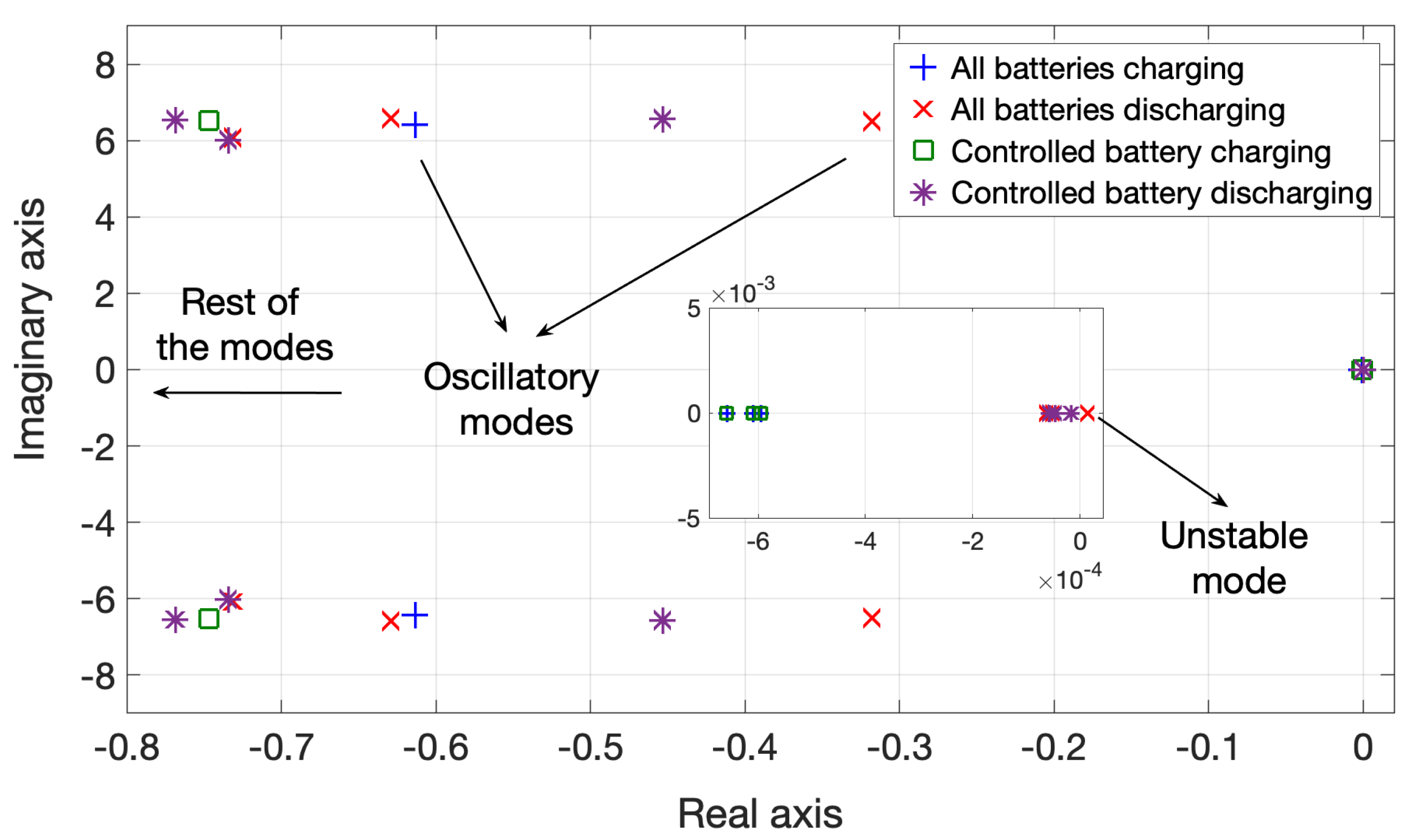
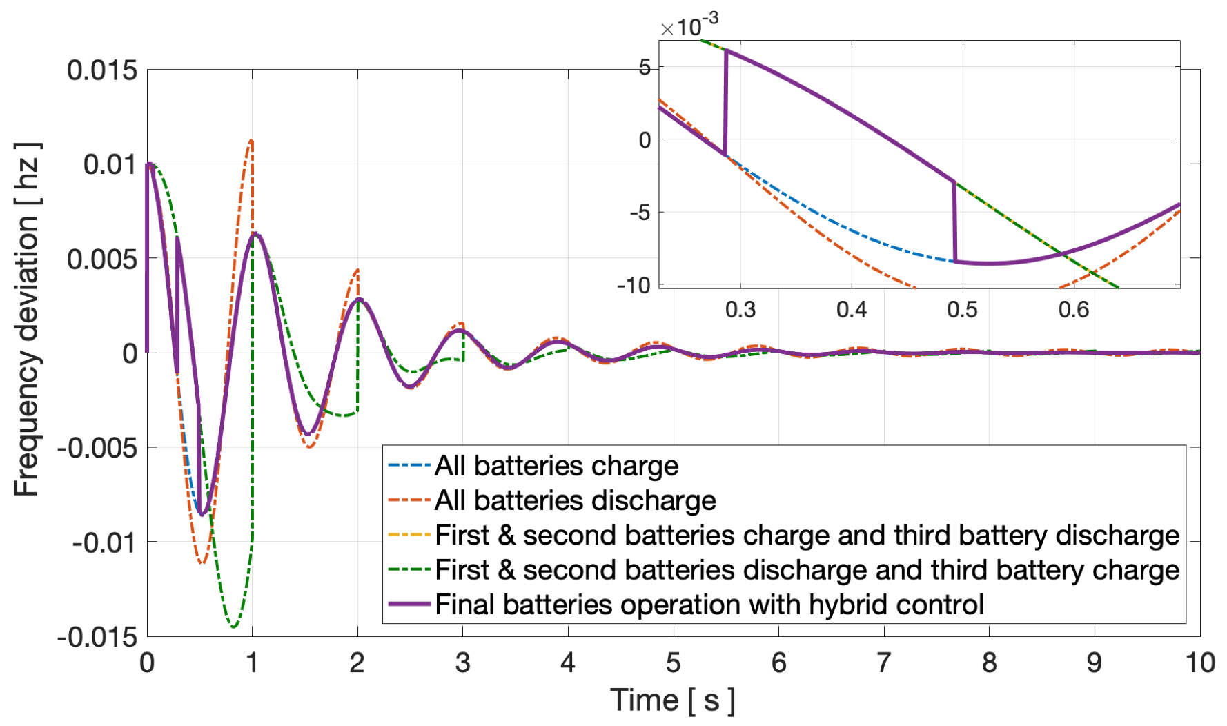
5.1. Case 1: Hybrid Battery Model

In this case, for the hybrid controller of the battery, we consider the switching time as ( t k 1 , t k ) = 1.5 s to guarantee the stability of the system. The hybrid controller selects the scenario with the minimum cost function as the operating mode for the given time interval. Then, the system’s states are updated based on the selected scenario and the selected L Q R control law for the next time slot. Consequently, the total cost function of the power system’s battery operation as the summation of three selected cost functions (associated with each scenario) is minimized.
The hybrid control in each step picks the optimum case, determining the batteries charging/discharging modes. The control strategy switches between charging and discharging modes to optimize the total operation cost and reduce the frequency deviations of the system, simultaneously.
To illustrate the effectiveness of the hybrid control on frequency deviations of the generators, one, three, and five (one generator from each area) are displayed in Figure 5, Figure 6 and Figure 7, respectively.
For the sake of simplicity, we only show the batteries’ operations for four scenarios out of the total eight cases. These scenarios are as follows: all batteries are charging; all batteries are discharging; first and second batteries are charging and the third battery discharging; first and second batteries are discharging and the third battery is charging. In Figure 5, Figure 6 and Figure 7, the dotted lines represent the generator’s frequency deviations for these four scenarios. The generator’s frequency deviations under the optimal switching policy with the hybrid controller are shown with solid purple lines. At the end of each time interval, the initial conditions of all scenarios are updated based on the selected scenario.

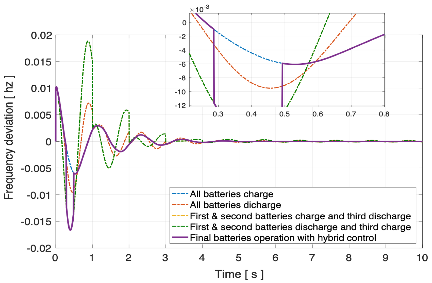
5.2. Case 2: WECC Battery Model

The eigenvalues of the case study model with the WECC model for battery dynamics are shown in Figure 8. The buses that batteries are connected to are the same for both approaches. Similar to the hybrid model, the uncontrolled WECC model battery integration can cause instability in the power system. Note that the system eigenvalues/poles depend on the buses that batteries are integrated into. By changing the connection bus, the eigenvalues of the system will change. Similar to the hybrid model, a decentralized suboptimal control is designed and applied for the WECC model to damp the frequency deviation in the system. The frequency deviations of generators one, three, and five (one from each area) are depicted in Figure 9, Figure 10 and Figure 11. The frequency regulations in each area are compared to the same generator in the hybrid model.

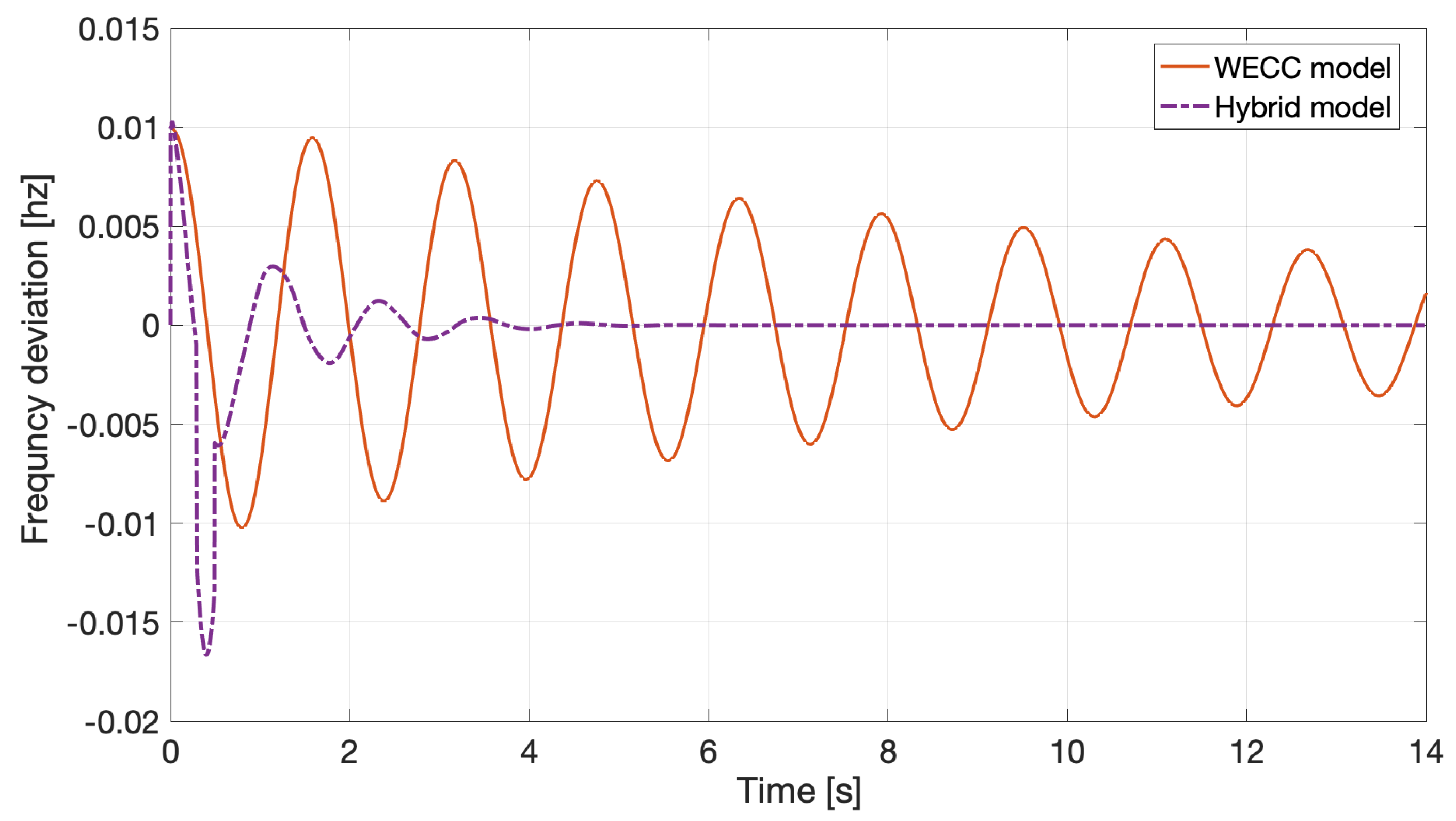
5.3. Result Discussion

By comparing the frequency deviations results of the case study model system with different battery model approach indicate the following:
  • Frequency deviations for the system with batteries modeled via hybrid model are suppressed faster, compared to the system with the WECC model for batteries.
  • Although the WECC model has two control inputs, the control design is more challenging, compared to the hybrid battery model.
  • Since the WECC model has fifth order dynamics, it has a strong inter-connectivity matrix, which serves as a major perturbation in the system.
  • The optimality index in the WECC model is 0.01 , which is lower than the smallest optimality index in the hybrid model.
Based on above mentioned observations in the control design for the case study model, it can be concluded that in general, the hybrid model is a sufficient model for the small-scale stability analysis in the power system. Unlike the WECC model, the hybrid model can be used for any stability analysis without specific regulation or any changes in the model representation. Inter-area oscillations are important phenomena in power system stability; the faster response time of the hybrid model is a unique and notable advantage for this dynamic model representation that should be taken into account for the power system analyses.
The main drawback of the hybrid model is the number of the controllers that should be designed for a power system. In hybrid models the number of the control design depends on the number of the batteries. However, in the frequency stability analysis, the power grid is divided based on the number of the dominant modes; so, the maximum number of the subsystems won’t be more than three areas.

6. Conclusions

In this paper, a decentralized LQR controller for an interconnected system is designed to damp the frequency oscillations via the battery’s output power. The batteries’ active and reactive output powers are regulated to control the frequency deviations in each area. In this study, we consider two different battery modeling approaches for the control design: a hybrid model and the WECC model. For each battery model, we design the optimal decentralized controller and compare their performance on damping the frequency deviations. The optimal decentralized control strategy is designed considering the total operation cost function for battery modes to optimize the batteries output power and suppress the frequency deviations. In the former case where the battery dynamics is modeled with a hybrid model, all charging and discharging scenarios for the batteries operations are considered and for each scenario, a decentralized optimal controller is designed. Then, a hybrid switching control is designed to select the best operating scenario for the batteries with minimum cost.
The results show (i) a notable improvement in the frequency deviations in the case study system for both the hybrid and WECC models, ( i i ) the hybrid model has better frequency damping, compared to the WECC model, ( i i i ) in spite of the WECC model’s higher degree of freedom in control inputs, the control design for the hybrid model is more convenient, due to the weak inter-connectivity of the system under hybrid dynamics of the battery; and ( i v ) the hybrid model frequency damping time depends on the switching time intervals.
Based on the hybrid and WECC battery dynamics models, it can be concluded that the WECC model is a proper model for smaller power systems, while the hybrid model has effective results in large-scale power systems with complex inter-connectivity.
For future work, a decentralized hybrid switching control will be designed for each area to study the impact of the batteries’ independent operations with the centralized hybrid control. In addition, the system’s stability under the switching operation will be investigated to guarantee the stability of the power system.

Author Contributions

Conceptualization, R.A.B., P.P. and D.S.; methodology, R.A.B., P.P. and D.S.; software, R.A.B., P.P. and D.S.; validation, R.A.B., P.P. and D.S.; formal analysis, R.A.B., P.P. and D.S.; investigation, R.A.B., P.P. and D.S.; resources, R.A.B., P.P. and D.S.; data curation, R.A.B., P.P. and D.S.; writing—original draft preparation, R.A.B., P.P. and D.S.; writing—review and editing, R.A.B., P.P. and D.S.; visualization, R.A.B., P.P. and D.S.; supervision, R.A.B., P.P. and D.S.; project administration, R.A.B., P.P. and D.S.; funding acquisition, R.A.B., P.P. and D.S. All authors have read and agreed to the published version of the manuscript.

Funding

The authors gratefully acknowledge the financial support from the U.S. Department of Energy’s Energy Storage Program, managed by Imre Gyuk. Sandia National Laboratories is a multi-mission laboratory managed and operated by National Technology and Engineering Solutions of Sandia, LLC., a wholly owned subsidiary of Honeywell International, Inc., for the U.S. Department of Energy’s National Nuclear Security Administration under contract DE-NA0003525.

Institutional Review Board Statement

Not applicable.

Informed Consent Statement

Not applicable.

Data Availability Statement

Not applicable.

Conflicts of Interest

The authors declare no conflict of interest.

References

  1. Aditya, S.K.; Das, D. Battery energy storage for load frequency control of an interconnected power system. Electr. Power Syst. Res. 2001, 58, 179–185. [Google Scholar] [CrossRef]
  2. Liang, L.; Zhong, J.; Jiao, Z. Frequency regulation for a power system with wind power and battery energy storage. In Proceedings of the IEEE International Conference on Power System Technology (POWERCON), Auckland, New Zealand, 30 October–2 November 2012; pp. 1–6. [Google Scholar]
  3. Strbac, G. Demand side management: Benefits and challenges. Energy Policy 2008, 36, 4419–4426. [Google Scholar] [CrossRef]
  4. Divya, K.C.; Østergaard, J. Battery energy storage technology for power systems—An overview. Electr. Power Syst. Res. 2009, 79, 511–520. [Google Scholar] [CrossRef]
  5. Integrating Renewable Electricity on the Grid, A Report by the American Physical Society (APS) Panel on Public Affairs. Available online: www.aps.org/policy/reports/popareports/upload/integratingelec.pdf (accessed on 5 August 2021).
  6. Setiadi, H.; Krismanto, A.U.; Mithulananthan, N. Influence of BES system on local and inter-area oscillation of power system with high penetration of PV plants. In Proceedings of the 2017 International Conference on Applied System Innovation (ICASI), Sapporo, Japan, 13–17 May 2017. [Google Scholar]
  7. Souvik, C.; Gayme, D.F.; Chakrabortty, A. Coordinating wind farms and battery management systems for inter-area oscillation damping: A frequency-domain approach. IEEE Trans. Power Syst. 2013, 29, 1454–1462. [Google Scholar]
  8. Héctor, P.P.; Wang, Y.; Silva-Saravia, H. On inertia distribution, inter-area oscillations and location of electronically-interfaced resources. IEEE Trans. Power Syst. 2017, 33, 995–1003. [Google Scholar]
  9. Boukarim, G.E.; Wang, S.; Chow, J.H.; Taranto, G.N.; Martins, N. A comparison of classical, robust, and decentralized control designs for multiple power system stabilizers. IEEE Trans. Power Syst. 2000, 15, 1287–1292. [Google Scholar] [CrossRef]
  10. Zecevic, A.; Siljak, D.D. Control of Complex Systems: Structural Constraints and Uncertainty; Springer Science & Business Media: New York, NY, USA, 2010. [Google Scholar]
  11. Singh, A.K.; Pal, B.C. Decentralized control of oscillatory dynamics in power systems using an extended LQR. IEEE Trans. Power Syst. 2015, 31, 1715–1728. [Google Scholar] [CrossRef] [Green Version]
  12. AlRifai, M.; Zribi, M. A robust decentralized controller for power system load frequency control. In Proceedings of the 39th International Universities Power Engineering Conference 2004 (UPEC 2004), Bristol, UK, 6–8 September 2004; Volume 2. [Google Scholar]
  13. Weitenberg, E.; Jiang, Y.; Zhao, C.; Mallada, E.; De Persis, C.; Dörfler, F. Robust decentralized secondary frequency control in power systems: Merits and tradeoffs. IEEE Trans. Autom. Control 2018, 64, 3967–3982. [Google Scholar] [CrossRef] [Green Version]
  14. Rezvantalab, J.; Kazemi, M.H.; Khaki Seddigh, A. Multi-area robust decentralized Load Frequency Controller design in a restructured power system using Quantitative Feedback Theory. In Proceedings of the 2009 International Conference on Electric Power and Energy Conversion Systems (EPECS), Sharjah, United Arab Emirates, 10–12 November 2009. [Google Scholar]
  15. Hamzeh, M.; Mokhtari, H.; Karimi, H. A decentralized self-adjusting control strategy for reactive power management in an islanded multi-bus MV microgrid. Can. J. Electr. Comput. Eng. 2013, 36, 18–25. [Google Scholar] [CrossRef]
  16. Xu, X.; Bishop, M.; Oikarinen, D.G.; Hao, C. Application and modeling of battery energy storage in power systems. CSEE J. Power Energy Syst. 2016, 2, 82–90. [Google Scholar] [CrossRef]
  17. Benigni, A.; D’Antona, G.; Ghisla, U.; Monti, A.; Ponci, F. A decentralized observer for ship power system applications: Implementation and experimental validation. IEEE Trans. Instrum. Meas. 2009, 59, 440–449. [Google Scholar] [CrossRef]
  18. Siljak, D.D. Decentralized Control of Complex Systems; Dover publications, Inc.: Mineola, NY, USA, 2018. [Google Scholar]
  19. WECC Second Generation Wind Turbine Models 012314. Available online: https://www.wecc.org (accessed on 5 August 2021).
  20. WECC Renewable Energy Modeling Task Force. WECC Battery Storage Dynamic Modeling Guideline. In Proceedings of the Western Electricity Coordinating Council Modeling and Validation Work Group, Denver, CO, USA, November 2016.
  21. Lu, C.F.; Liu, C.-C.; Wu, C.J. Dynamic modelling of battery energy storage system and application to power system stability. IEE Proc. Gener. Transm. Distrib. 1995, 142, 429–435. [Google Scholar] [CrossRef] [Green Version]
  22. Biroon, R.A.; Pisu, P.; Schoenwald, D. Large-Scale Battery Energy Storage System Dynamic Model for Power System Stability Analysis. In Proceedings of the Texas Power & Energy Conference (TPEC), College Station, TX, USA, 6–7 February 2020. [Google Scholar]
  23. Biroon, R.A.; Abdollahi, Z.; Hadidi, R. Frequency Control by Tariff Regulation: A comparison between the MPC and Tariff Modification. In Proceedings of the 2020 IEEE Texas Power and Energy Conference (TPEC), College Station, TX, USA, 6–7 February 2020. [Google Scholar]
  24. Hannu, L.; Saari, P.; Komulainen, R. Voltage and frequency control of inverter based weak LV network microgrid. In Proceedings of the 2005 International Conference on Future Power Systems, Amsterdam, The Netherlands, 18 November 2005. [Google Scholar]
  25. Biroon, R.A.; Pisu, P.; Schoenwald, D. A Hybrid Control Framework for Large-Scale Battery Integration to the Power System for Stability Analysis. In Proceedings of the American Control Conference (ACC), Denver, CO, USA, 1–3 July 2020. [Google Scholar]
  26. Shubhanga, K.N. Power System Analysis, a Dynamic Presentation; Pearson: New Delhi, India, 2018. [Google Scholar]
  27. Padyar, K.R. Power System Dynamics Stability and Control; John Wiley & Sons: Hyderabad, AP, India, 2002. [Google Scholar]
  28. Biroon, R.A. Battery Integration to the Power Grid and Frequency Regulation. Ph.D. Thesis, Clemson University, Clemson, SC, USA, 2020. [Google Scholar]
  29. Chow, J.H. Power System Coherency and Model Reduction; Springer: New York, NY, USA, 2013; Volume 84. [Google Scholar]
  30. Rogers, G. Power System Oscillations; Springer Science & Business Media: New York, NY, USA, 2012. [Google Scholar]
  31. Yukai, C.; Macii, E.; Poncino, M. A circuit-equivalent battery model accounting for the dependency on load frequency. In Proceedings of the Design, Automation & Test in Europe Conference & Exhibition (DATE), Lausanne, Switzerland, 27–31 March 2017. [Google Scholar]
  32. Baek, D.; Chen, Y.; Bocca, A.; Bottaccioli, L.; Di Cataldo, S.; Gatteschi, V.; Pagliari, D.J.; Patti, E.; Urgese, G.; Chang, N.; et al. Battery-aware operation range estimation for terrestrial and aerial electric vehicles. IEEE Trans. Veh. Technol. 2019, 68, 5471–5482. [Google Scholar] [CrossRef]
  33. Liberzon, D.; Morse, A.S. Basic problems in stability and design of switched systems. IEEE Control Syst. Mag. 1999, 19, 59–70. [Google Scholar]
  34. Morse, A.S. Supervisory control of families of linear set-point controllers—Part 1: Exact matching. IEEE Trans. Autom. Control 1996, 41, 1413–1431. [Google Scholar] [CrossRef]
  35. Lin, H.; Panos, A.J. Stability and stabilizability of switched linear systems: A survey of recent results. IEEE Trans. Autom. Control 2009, 54, 308–322. [Google Scholar] [CrossRef]
  36. Pourbeik, P.; Williams, S.E.; Weber, J.; Sanchez-Gasca, J.; Senthil, J.; Huang, S.; Bolton, K. Modeling and dynamic behavior of battery energy storage: A simple model for large-scale time-domain stability studies. IEEE Electrif. Mag. 2015, 3, 47–51. [Google Scholar] [CrossRef]
Figure 1. Three-area power system case study model.
Energies 14 05605 g001
Figure 2. Eigenvalues of the system in the presence of batteries.
Energies 14 05605 g002
Figure 3. Case study model frequency deviation in the presence of the decentralized controlled batteries.
Energies 14 05605 g003
Figure 4. Hybrid control schematic.
Energies 14 05605 g004
Figure 5. Frequency deviations of the generator number one in the first area for different scenarios and hybrid control final decision.
Energies 14 05605 g005
Figure 6. Frequency deviations of the generator number three in the second area for different scenarios and hybrid control final decision.
Energies 14 05605 g006
Figure 7. Frequency deviations of the generator number five in the third area for different scenarios and hybrid control final decision.
Energies 14 05605 g007
Figure 8. The eigenvalues of the case study model with WECC model for battery dynamics.
Energies 14 05605 g008
Figure 9. First generator frequency deviation in the first area.
Energies 14 05605 g009
Figure 10. Third generator frequency deviation in the second area, 1.
Energies 14 05605 g010
Figure 11. Third generator frequency deviation in the second area, 2.
Energies 14 05605 g011
Publisher’s Note: MDPI stays neutral with regard to jurisdictional claims in published maps and institutional affiliations.

