1. Introduction
Liquefied natural gas (LNG) plants frequently encounter torsional resonance phenomena when high power electrical motors are supplied by variable frequency drives (VFDs). This is due to the interactions among the VFDs and the turbine-generator (TG) units which cause torsional vibrations known as sub-synchronous torsional interactions (SSTIs) [
1,
2,
3,
4]. SSTI contingency has to be considered on the case of LNG plants’ transient operation such as load variations. An analysis of these phenomena with considerations about the stability of the LNG plants is presented in [
1,
2]. Nevertheless, SSTI phenomena have been experienced and studied previously in other applications, such as in wind farms [
5,
6].
In an LNG plant, SSTIs lead to instability when the TG unit’s overall electromechanical damping is negative [
1,
2]. The overall damping of a TG unit consists of mechanical damping and electrical damping [
7]. The mechanical damping is positive while the electrical damping is influenced by the devices included in the electromechanical system and it can be negative. In [
2], electrical damping assessment and sensitivity analysis are provided to evaluate the impact of the LNG plant’s control system-parameter’s variation on the SSTIs phenomena. The study is customized considering a real LNG plant operating in several configurations which differ in number of TG units, number of VFDs and TG unit power. In the same paper the authors demonstrated that a fine tuning of the control parameters should be adopted in LNG plants’ practice reducing the risk of torsional instability. However, in [
2] it is also highlighted how, in such peculiar configurations, the SSTIs risk cannot be avoided by acting only on the tuning of the control system parameters.
In case the torsional stability cannot be achieved by varying the control system parameters, a dedicated power-electronics-based equipment can be included in the electromechanical system to solve instability. In literature, some solutions based on power converters have been adopted to manage sub-synchronous resonance (SSR) [
8,
9,
10,
11,
12]. In [
8,
9] a thyristor-controlled series capacitor is introduced as an attractive method for SSR mitigation; while in [
11], the performances provided by a thyristor-controlled series capacitor compensator are compared with the performances obtained using a series capacitor. In [
12] an active damper based on a high-bandwidth power converter is employed. In particular, the active damper is located at the point of common coupling (PCC) modifying the equivalent impedance of the power network and mitigating the resonant phenomena. In [
9] small-signal analysis is used to investigate the effects of a static synchronous compensator, originally installed to regulate the network voltage, on the power system oscillations.
With regard to SSTI phenomena, an active damper based on an adaptive active filter is proposed in [
13] to increase the damping of the electro-mechanical vibrations. A thyristor power converter which increases the oscillation modes’ natural damping in the rotating shaft assembly is presented in [
14]. The main differences of the methods in [
13,
14] are the input signals of the damper converter control system. In the first case, the input signal is derived from the electrical frequency of the generator stator current [
13]; in the second one, the input signal is obtained by the generator rotor speed [
14]. However, both methods exhibit high performances as concluded in [
15].
Considering the LNG plant configurations examined in [
2], in this paper a sub-synchronous damper (SSD) based on a thyristor rectifier is presented to mitigate torsional oscillations. The power converter is controlled to provide an additional torque oscillation at the air-gap of the TG unit, as introduced in [
16] and developed in [
17]. The additional torque can be expressed as the sum of the synchronous torque and the damped torque, in accordance with the complex torque coefficient method. As described in [
18,
19,
20], the damped torque can be used to reduce the sub-synchronous oscillations, since it modifies the overall damping of the TG units. The damping increases or decreases according to the phase difference between the additional torque and the relative torsional speed of the TG unit.
It is common practice [
13,
17,
21] to operate the SSD with a constant phase. Unfortunately, this approach allows for satisfying performance only for a set of the power system possible configurations. These results are unattractive in island-mode operation when the variability of the equivalent impedance is not negligible. For this reason, in this paper a new SSD phase control system is presented and characterized by an adaptive reference signal; in particular, the phase of SSD current reference is adjusted on the basis of the torsional torque oscillations measurement. As in [
21], the SSD regulates the phase of the additional torque provided at the TG air-gap. Differently from [
21], the amplitude of the torsional oscillations is used to estimate the TG overall damping and to determine the exact phase of the SSD current.
The rest of the paper is organized as follows: in
Section 2 the case study is presented; in
Section 3 the theoretical relationship between the electromechanical torque variation and electrical damping is investigated; in
Section 4 the overall SSD control system is analyzed;
Section 5 provides the results considering four different configurations of the plant; and finally,
Section 6 is focused on final remarks.
2. Liquefied Natural Gas Plant: Case Study
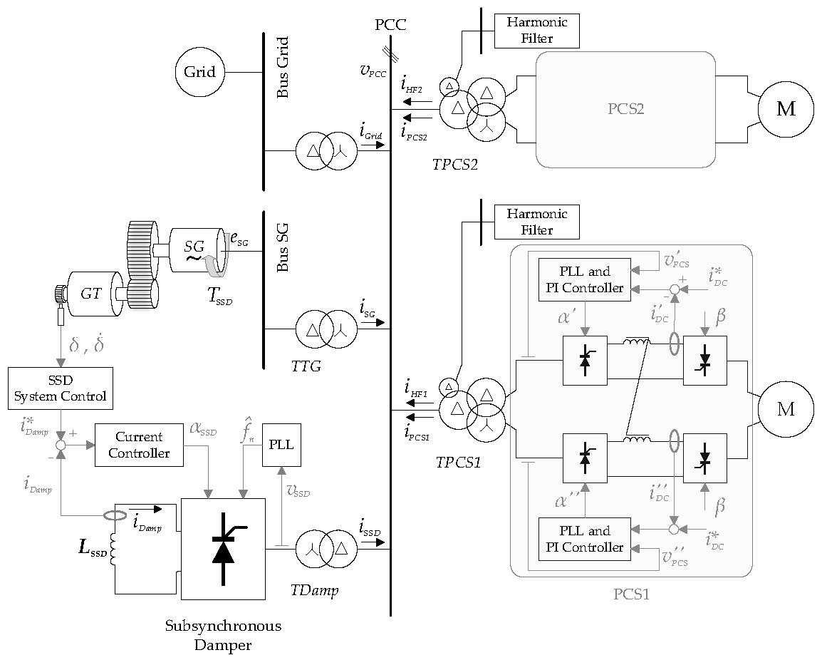
The LNG plant under analysis is shown in
Figure 1. The considered power system consists of three identical TG units with an installed capacity of 44 MVA and two 16 MVA compression trains coupled to thyristor variable frequency drives (TVFDs). Furthermore, for each compression train a harmonic filter (HF) is connected to the point of common coupling (PCC) to compensate the harmonic currents of the TVFD. The circuits are designed to cut off the 5th, 7th and 11th harmonics. The plant operates in island mode with a PCC voltage (
) equal to 30 kV. In order to simplify the analysis, the overall loads connected to the power system are taken into account through a lumped load. In
Figure 1 the other TG units and the lumped load are represented by the generic block denoted as “Grid”.
Table 1 reports the rated data related to the real LNG plant under analysis.
For the sake of simplicity,
Figure 1 represents only one TG unit, that is composed of a gas turbine (GT) coupled through a gearbox to the synchronous generator (SG). The SG is connected to the PCC through a step-up transformer, denoted as TTG. As in [
1,
2], the control system of the SG includes an automatic voltage regulator (AVR) and a power system stabilizer (PSS) in compliance with [
22].
The TVFDs, denoted as power conversion stage 1 (PCS1) and power conversion stage 2 (PCS2), supply two 6-phase synchronous motors (Ms). Ms act as starter and helper motors, allowing start-up of the entire compression train and providing additional power when required. Each TVFD is connected to the PCC through a step-down transformer with two secondary windings. The step-down transformers are indicated with TPCS1 and TPCS2. Each TVFD consists of two line-commutated-converters (LCCs). Each LCC is a double-stage converter since the first stage is a line-commutated-rectifier (LCR), while the second stage is a line-commutated-inverter (LCI). The control scheme of the TVFD first stage is depicted in
Figure 1. The DC-link currents are controlled by means of two PI controllers which set the firing angles α′ and α″. In contrast, the second stage of the TVFD operates with constant firing angles denoted as β. Two phase locked loops (PLLs) provide synchronization with the voltages
and
. Further details can be found in [
1,
2].
In [
2], it was highlighted that high risk related to SSTI phenomena is verified when only one TG unit supplies the entire power system. For this reason, in this paper an SSD converter is connected to the PCC through the step-down transformer (
TDamp) to reduce the TG unit sub-synchronous torsional oscillations.
The SSD converter consists of an H-bridge based on thyristors and of an
LSSD inductance. The current provided by the SSD converter at the DC-link is denoted as
iDamp. It can be expressed as the sum of a direct component (
IDamp) and superimposed oscillations. It results in:
where
ah,
ωh and
φh represent, respectively, the magnitude, the angular frequency and the phase of each current oscillation at the DC-link.
As discussed in [
3], torque oscillation with angular frequency
ωh is verified at the TG air-gap. As a consequence, TG torsional damping at the frequency
fh can be related to the oscillation of the current
iDamp at the same frequency.
3. Electromechanical Torque Variation and Electrical Damping
The TG unit shown in
Figure 1 can be described by a lumped model characterized by 59 degrees of freedom (DOFs). The shaft torsional dynamics are defined by the system of differential equations based on Newton’s second law. It results in:
where
δ is the DOF angle vector,
J is the inertia diagonal matrix,
K is the tri-diagonal stiffness matrix,
R is the damping matrix and
T is the vector of the torque applied to the TG shaft. The vector
T includes the driving torque
TGT and the SG electromechanical torque
TE.
In order to simplify, the torsional study of the TG shaft, (2) is expressed through modal analysis. Considering the coordinate transformation expressed in (3), the modal approach [
23,
24,
25,
26] allows obtaining a system of uncoupled equations. It results in:
with
where
is the vector of the modal coordinates and Φ is the eigenvectors matrix of the
matrix.
Considering the complex torque coefficient method [
18,
19,
20] and evaluating the results obtained in [
1,
2], how the modal electric torque Φ
T∙TE at the generic TNF is linked to the damping can be assessed. In particular, small-signal analysis is carried out on the modal coordinate Δ
qTNF. The relative speed deviation can be obtained through the time derivative (8). The electromagnetic torque increment can be expressed as the sum of the synchronous torque and the damped torque (9). It results in:
where
is the row vector of
related to the generic TNF and
ke(
TNF) and
re(
TNF) are the stiffness coefficient and the damping coefficient. These coefficients are dependent on all the devices included in the electromechanical system (TG units, power conversion stages, HFs, lumped load and SSD).
Neglecting the modal driven torque contributes Φ
T∙
TGT, (9) can be replaced in (4). For the generic TNF the torsional dynamics can be represented by the following equation:
where
j(
TNF),
rm(
TNF) and
km(
TNF) are, respectively, the diagonal element of the modal inertia matrix
j, the modal damping matrix
r and modal stiffness matrix
k (for the considered TNF). They depend solely on the mechanical characteristics of the TG.
It can then be pointed out that
ke(
TNF) influences the value of the TG natural frequency while
re(
TNF) influences the damping value associated to the TG unit. It represents an extension of what is discussed in [
1,
2].
The electromechanical torque variation (
) due to the modal speed oscillation (
) can be evaluated starting with (9). It results in:
Equation (11) consists of two terms which can be expressed as the function of
, where
is the angle between the electromechanical torque oscillation and the torsional speed oscillation:
Since the electrical damping
ξe(
TNF) can be defined as:
the electrical damping
ξe(
TNF) is positive, and the torsional instability is avoided, when the phase
is in the range of 90–270°. If
exceeds this range,
ξe(
TNF) becomes negative.
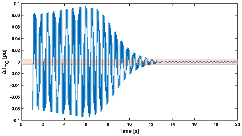
Considering the homogeneous equation associated with (2), a preliminary analysis of the TG unit can be developed. The TG unit has two sub-synchronous TNFs below the network rated frequency (
fn = 50 Hz):
TNF1 = 9.2 Hz and
TNF2 = 31.5 Hz. Hence, the sub-synchronous torsional dynamics are assessed through (4) where the matrixes
j,
r and
k are calculated using the parameters reported in
Table 2. It has to be considered that the rigid component of the TG shaft line is denoted as
j(0). Looking at
Table 2, all the data are related to the real LNG plant under analysis and they are provided by Baker Hughes mechanical engineering department.
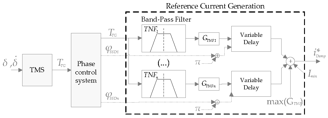
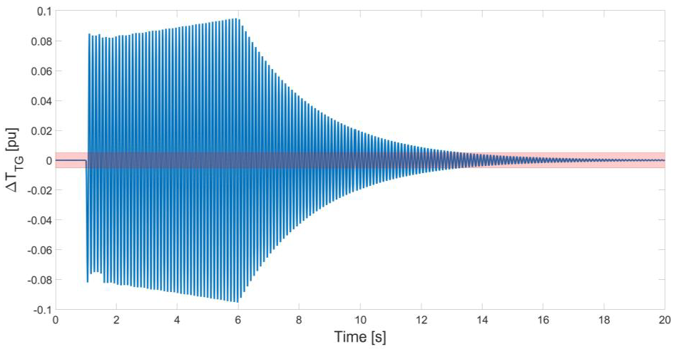
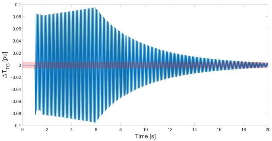
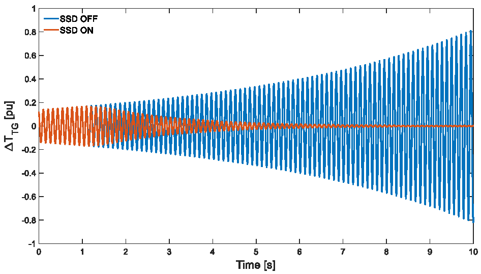
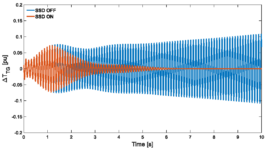
4. Sub-Synchronous Damper (SSD) Converter and Control System
In order to increase the electrical damping of the TG units and to avoid torsional instability, a dedicated converter is connected to the PCC (
Figure 1). The SSD consists of an LCR operating at the grid frequency
fn.
The SSD converter is controlled to provide an additional torque oscillation ΔTSSD increasing the electrical damping. In accordance with (12), ΔTSSD mitigates the sub-synchronous oscillations only if the phase shift , related to the speed oscillation ΔωSG, is within the range of 90–270°.
Considering the dynamics associated with the generic TNF, the phase difference
between the speed oscillation Δ
ωSG and the additional torque oscillation Δ
TSSD is composed of three contributors. The first one is denoted as
and it represents the phase difference between the additional torque oscillation Δ
TSSD and the stator current oscillation
, measured in a synchronous reference frame rotating at the grid pulsation
ωn. The second one is denoted as
and it is the phase difference between the stator current oscillation
and the SSD current oscillation
.
depends on the equivalent impedance of the plant and by the plant configuration. The third one is denoted as
and it represents the phase difference between the SSD converter reference current
and the speed oscillation Δ
ωSG. It results in:
As a consequence, the SSD control system is designed to include a phase control system determining the proper value of
. The proper value of
has to verify the following condition at each sub-synchronous oscillation frequency:
Starting from the measurements of the DOF angle vector and torsional speed (
and
), the torsional monitoring system (TMS) allows achieving the Δ
ωSG of the turbine toothed wheel at the point of measurement [
27]. The resulting alternating torque Δ
TTG expressed per-unit is calculated on the basis of the detailed torsional model of the shaft-line and it is used to generate the proper SSD converter reference current
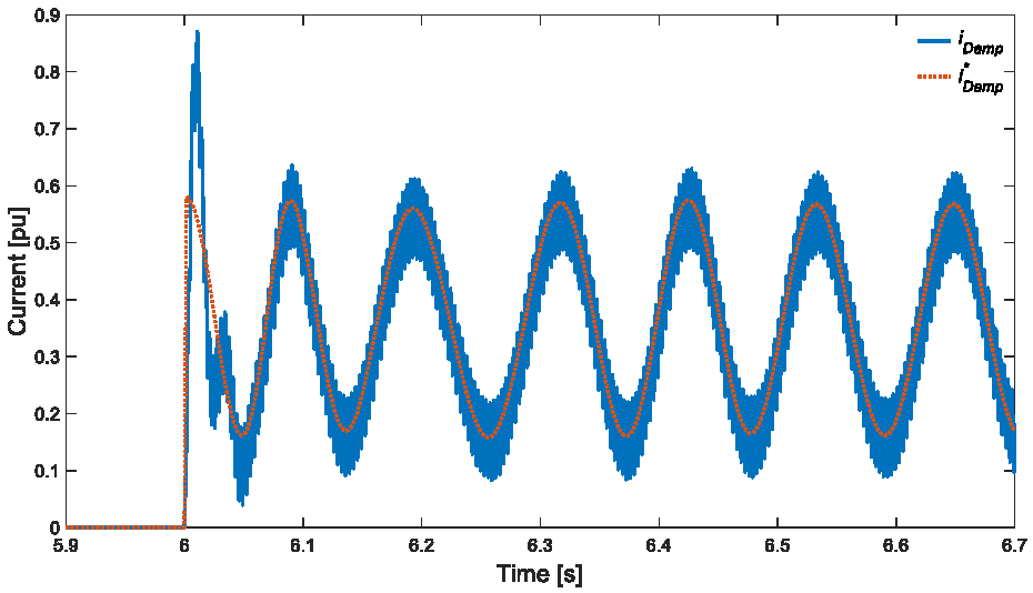
. The reference current
represents the desired SSD DC-link current. The signal
can be expressed as:
where
Imin is a constant value set in order to avoid discontinuous conduction of the LCR,
is provided by the SSD phase control system (
Figure 2) and
GTNF is a proportional gain designed to guarantee sufficient damping.
The current reference
is generated by the reference current generation (RCG) block in the SSD control system shown in
Figure 2.
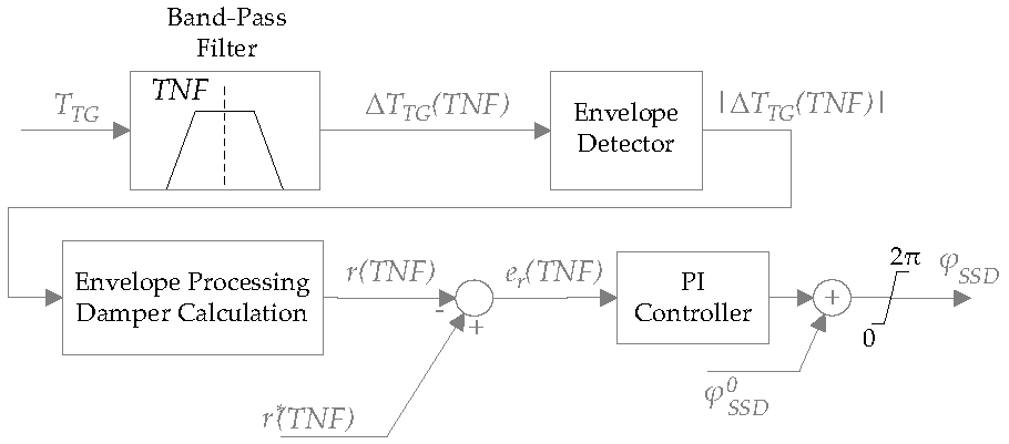
Looking at
Figure 2, for each sub-synchronous TNF, a band-pass filter is applied to the
TTG signal. The natural frequencies, characterizing the band-pass filters, are selected considering the preliminary assessment with regards to the homogeneous equation associated to (4). These frequencies can be considered fixed, because each TNF is mainly determined by the mechanical parameters of the TG units. The appropriate compensation phases
,
, etc., for different TNFs, can be considered as decoupled signals, which represent the outputs of the phase control system and the inputs of the RCG block. The phase shifts are sufficient to satisfy the condition in (16) for the corresponding frequencies. The proportional gain for each mode (
GTNF1,
GTNF2, etc.) has to be tuned in order to provide proper damping torque for SSTI phenomena reduction.
Finally, looking at
Figure 1, a PI current controller determines the firing angle of the SSD converter, denoted as
, which is used to regulate the current
on the DC-link. A PLL guarantees synchronization with the voltage
at the secondary side of the transformer
TDamp.
The proper tuning of the SSD current controller parameters (
KSSD and
TSSD) is achieved through the zero-pole placement method considering that the LCR model is derived on the basis of the 12-pulse H-bridge rectifier model developed in [
2]. The electrical and control system parameters of the proposed SSD are reported in
Table 3.
Considering the generic TNF, it could be possible to adopt a simpler control strategy as previously proposed in [
13,
17,
21] where: a constant value of
is set to verify the condition in (16);
could be exactly determined through the SG electrical parameters; and
could be estimated, for example, through time-domain simulation software [
17]. However, the assessment of
depends on the equivalent network impedance. Hence, the methods described in [
10,
14,
18] do not allow maximizing of the damping related to the additional torque Δ
TSSD working with a constant
value.
Starting from this consideration, the phase control proposed in this paper allows improving of the SSD converter operation. The phase control is included in the SSD control system as shown in
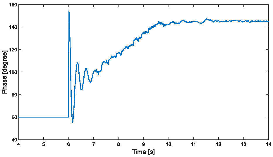
Figure 2 and it is analyzed in detail in the following subsection. The phase control system regulates
in order to achieve a phase difference
. This condition maximizes the electrical damping with reference to (12) and (14).
Phase Control System
The phase control system is based on the estimation of the damping matrix component
r(
TNF) starting from the torque signal
TTG. In particular, at the SG mid-section, the angular displacement Δ
δi is measured and this measurement is used to calculate the torque
TTG. It results in:
where
Ki is the stiffness coefficient related to the angular displacement Δ
δi.
In a modal representation, the torsional behavior of the TG unit is described by a homogeneous differential (10). Assuming that
ke(
TNF) is negligible compared to
km(
TNF), the sub-synchronous dynamics of the generator unit are represented at the frequency
TNF by the following motion equation:
with
and where
is the module relative to the angular displacement which depends on the boundary conditions. The modal transformation expressed in (3) and Equation (18) can be used to express the oscillation of the torque
TTG as a function of the modal variables.
Considering the eigenvectors matrix Φ defined as:
the torque oscillation at the frequency
TNF can be expressed as:
Combining (19) and (22), it results in the envelope related to the torque oscillation (|Δ
TTG(
TNF)
|) having the same exponential trend of the modal variable
:
As shown in
Figure 3, the calculated torque
TTG is filtered by a band-pass filter in order to obtain the oscillation Δ
TTG(
TNF) at the considered
TNF. The measured torque is processed to obtain its envelope and, on the basis of (23), the damping matrix component
r(
TNF) is estimated as follows:
The reference signal represents an input signal for the phase control system. The phase control is based on a PI controller which processes the error signal . The proportional gain and the integral time constant of the PI controller are denoted as KPC and TPC, respectively.
In order to maximize the damping provided by the SSD, the signal reference
has to be calculated considering the maximum achievable electrical damping. Denoting the maximum electrical damping as
ξeMAX(
TNF),
can be expressed as:
where
ξm(
TNF) is the mechanical damping at the considered TNF of the TG unit and it depends only on the mechanical parameters.
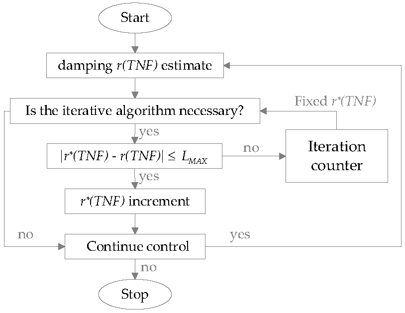
It should be considered that the value of ξeMAX(TNF) is not commonly known a priori. It depends on known values such as the amplitude of the iSSD current fluctuations and on unknown values such as the power network equivalent impedance. Hence, the reference can be varied according to an iterative algorithm designed to optimize the SSD damping action.
The adaptive reference can be generated considering the flowchart shown in
Figure 4. The damping coefficient
r(
TNF) is acquired with the desired sampling rate.
r(
TNF) is then compared with
. If the error signal (
) is higher than the maximum permissible error
LMAX, the reference value is not varied, and the system converges to the desired damping value. Otherwise, the damping value must be adjusted to find the maximum achievable damping. The algorithm stops when the iterations counter registers that the settling time of the phase control is higher than
TMAX.
TMAX denotes a time constant tuned depending on the electro-mechanical system dynamics. When this condition is verified, the reference signal is maintained constant and it is set equal to the value determined at the previous iteration. This value corresponds with the highest damping which can be provided by the system.
The number of interactions required to achieve the algorithm convergence depends on the SSD power and the initial value of the signal .


